EP1908680A2 - A sunroof system - Google Patents
A sunroof system Download PDFInfo
- Publication number
- EP1908680A2 EP1908680A2 EP07253783A EP07253783A EP1908680A2 EP 1908680 A2 EP1908680 A2 EP 1908680A2 EP 07253783 A EP07253783 A EP 07253783A EP 07253783 A EP07253783 A EP 07253783A EP 1908680 A2 EP1908680 A2 EP 1908680A2
- Authority
- EP
- European Patent Office
- Prior art keywords
- chain
- panel
- block
- carriage
- guide rail
- Prior art date
- Legal status (The legal status is an assumption and is not a legal conclusion. Google has not performed a legal analysis and makes no representation as to the accuracy of the status listed.)
- Granted
Links
Images

Classifications
-
- B—PERFORMING OPERATIONS; TRANSPORTING
- B63—SHIPS OR OTHER WATERBORNE VESSELS; RELATED EQUIPMENT
- B63B—SHIPS OR OTHER WATERBORNE VESSELS; EQUIPMENT FOR SHIPPING
- B63B17/00—Vessels parts, details, or accessories, not otherwise provided for
- B63B17/02—Awnings, including rigid weather protection structures, e.g. sunroofs; Tarpaulins; Accessories for awnings or tarpaulins
Definitions
- the present invention relates to a sliding sunroof system.
- the system is particularly suitable for use on a boat, especially a luxury pleasure boat.
- roof panels similar in concept to a car sunroof.
- Such roofs provide the user with a degree of flexibility when steering a boat in respect of their being open to the weather conditions.
- roof panels are constructed from lightweight materials they are nevertheless still heavy and means are normally included to facilitate movement between the closed position and a partially or fully open position.
- Features which provide smooth or low friction movement are known, but increasingly motors are included to drive the panel.
- a final consideration for a sunroof system is its ease of installation and, where necessary, repair. It would be advantageous therefore if a system were to be easy to incorporate into a boat design.
- a sunroof system for a pleasure boat having a sliding roof panel, and further including an endless chain, connected to a panel by connection means, and a motor to drive the endless chain; the chain being constrained to run within a guide rail having a base section, with side walls depending from the edge thereof to form a U-shaped channel, the free edge of each side wall ending in a flange element orientated perpendicularly thereto and whereby the flange elements define a space therebetween, leaving the channel open along one surface, the connection means engaging and being supported by the surfaces of the flange elements.
- the system can be easily installed and allows the panels to move freely between an open and closed position whilst allowing the panel to safely flex.
- the system includes a chain guide located within the channel, the chain guide separating portions of the chain moving in opposite directions.
- the guide reduces wear and tear on the chain and prevents undesired motion and harmonics building up.
- the chain guide is particularly preferably in two sections to facilitate assembly. Especially preferably the two sections are so profiled to provide one or more gaps between the sections along contacting surfaces. The provision of the gaps minimises the chance of the sections not sitting well against each other.
- connection means preferably engages the flange elements by means of rollers.
- the rollers run on the flange elements to provide a smooth operation.
- the or each roller includes one or more flanges, engaging the edge of the flange elements. The flanges on the roller prevent lateral movement of the panel with respect to the guide rails.
- connection means optionally includes a block engaging the underside of a flange element and gripping the flange element between the block and a roller.
- the block is formed of resilient material to dampen down vibrations.
- the block includes resilient means. Such vibrations, arising for example from the motion of the boat or from the engine can cause noise and also wear on the system elements.
- the block is yet further optionally urged against the flange element by a pin or similar fixing means to ensure good contact.
- connection means is operably connected to the chain by a toothed pick up, the teeth of the pick up sitting into the gaps between the links in the chain.
- a brush pile is advantageously located in the guide rail to reduce noise and to hinder ingress of dirt into the rail which might cause damage.
- the system preferably includes tensioning means adjustable to remove slack from the chain.
- a sunroof system for a pleasure boat having a sliding roof panel, and further including a rack and a pinion, connected to a panel by connection means, a motor to drive the rack and a pinion; the rack being constrained to a guide rail having a base section with side walls depending from the edge thereof to form a U-shaped channel, the free edge of each wall ending in a flange element orientated perpendicularly thereto and whereby the flange elements define a space there between, leaving the channel open along one surface, the connection means engaging and being supported by the surfaces of the flange elements.
- the attached drawings show a system to enable a sunroof panel to be moved between an open and closed position.
- the system moreover provided is designed to be robust towards flexing of the panel and to minimise the noise produced during panel movement.
- the system is designed primarily for use within luxury boats. Typically such boats are of length 15 to 30 metres and the panels under consideration approximately rectangular in shape and of dimension 2-4 metres.
- Such panels are designed to be relatively strong but lightweight and can be formed of plastics materials, glass fibre or carbon composites.
- a prime component is an elongate guide rail 10, formed from aluminium or steel, which is set into a gutter or channel 11 beneath a roof panel 12.
- the guide rail 10 has a base plate 13.
- Two side walls 14 depend perpendicularly upwardly, from the base plate 13 to define a U-shaped channel.
- Flanges 15, 16 are located perpendicularly across the free edge of each side wall 14, and provide support for movement of the panel 12.
- an endless chain 17 of typically 3 ⁇ 8" (0.95cm) pitch is provided, the chain being operably connected to a motor and to the panel 12.
- the chain 17 is located wholly within the U-shaped channel of the guide rail 10, and describes an upper path 18 and a lower path 19 as part of a loop.
- the lower path 19 of the chain 17 is supported by a ridge 21 on a lower chain guide 20.
- Resting on the lower chain guide 20 is an upper chain guide 22.
- the upper chain guide 22 has a first ridge 23 which depends downwardly from the upper chain guide 22, co-operating with the ridge 21 to constrain lateral and vertical motion of the chain 17.
- This feature reduces wear on the chain 17, and also noise due to rattling of the chain 17. Moreover, impact of the boat's motion on the chain's motion is minimised.
- a second ridge 24 is also provided on the upper chain guide 22 to support the chain 17 as it moves along the upper path 18.
- ridges 25a, 25b are provided on the guide rail 10.
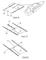
- FIGS 3a and 3b illustrate the tensioning block and the drive means.
- tensioning means are provided. Two options for tensioning means are illustrated, which act in similar fashion.
- the tensioning means comprise an idle sprocket 30 around which the chain (not shown in Figures 3a, 3b) passes.
- the sprocket 30 is connected to the tensioning block 31 whose operation enables the position of the sprocket 30 to be moved within the guide rail 10. By suitable adjustment of this position the effective path length of the chain 17 is altered. This feature facilitates installation of the system and also provides rapid correction if the chain 17 becomes slack after having been in use.
- the location of the sprocket 30 and the tensioning block 31 is at the discretion of the operator and depends upon compatibility with the particular boat in which the system is being used.
- Motion of the chain 17 is provided by a motor which connects through, via a drive shaft 32, to a drive sprocket 33 located within the guide rail 10.
- Figure 3a provides two options for the location of the tensioning block 31.
- Figure 3b shows two options for the location of the drive sprocket 33, the choice of location depending upon the installation position of the motor.
- the drive sprocket 33 is supported by a block which supports the drive shaft 32 and also provides clearance for a carriage (see below) to run over the elements of the tensioning means.
- the drive shaft 32 can be connected to the drive motor via universal joints and coupled shafts, although alternative connections such as flexible drive shafts can be used where suitable.
- Motion of the chain 17 is coupled to the roof panel 12 through a carriage 40 illustrated in Figures 4a, 4b and 5.
- the carriage 40 is connected to and supports the panel 12 and the chain 17, and is itself supported on the guide rail 10.
- the motor drives the chain 17 therefore, the carriage 40 and the panel 12 are moved along in the same direction.
- the carriage 40 has two carriage brackets 41 to provide a support framework for the other carriage elements.
- two rollers 42a, 42b are mounted on axles 43a, 43b.
- the axles 43a, 43b pass through holes defined in the brackets 41. Where suitable, the axles can be incorporated as an integral part of the rollers 42a, 42b.
- Each roller 42a, 42b is profiled by incorporation of roller flanges 44.
- the rollers surfaces 45 rest on the upper surface of the guide rail flanges 15, 16 whilst the roller flanges 44 are contiguous with the inwardly facing edges of the flanges 15,16.
- the roller flanges 44 and the roller surfaces 45 co-operate therefore with the flanges 15,16 to keep the carriage 40 correctly aligned.
- Each bracket 41 also supports a generally elongated block 46 held in position on the bracket 41 by means of fixing means 47 passing through holes in the bracket 41 and into the block 46.
- the block 46 is resilient in nature, resilience being provided firstly by the shape of the block 46 having a cut away portion 48 allowing the remaining portions 49 to flex.
- the block 46 is formed of a resilient material. In use the block 46 engages and is urged against the underside of the lower surface of the flange 15, 16. To further urge the block 46 against the flange 15,16 a pin 50 passes through the block 46.
- roller surfaces 45 therefore co-operate with the block 46 to restrict vertical movement of the carriage 40. Such vertical movement may be occasioned by motion of the boat or engine vibrations.
- connection column 51 The carriage 40 is coupled to the panel 12 by a connection system, simply illustrated as the connection column 51.
- the connection column 51 is typically formed of a material such as to provide a strong member able to withstand the forces generated by the boat and the panel's movement.
- a connection bracket 52 supports and connects the column 51 to the carriage 40.
- a pick-up 60 (shown in Figure 6) is fixed to the lower portion of the carriage 40 by fixing means which pass through the apertures 61.
- the pick-up 60 is provided with teeth 62 which sit between the links of the chain 17 and thereby couple the chain 17 to the carriage 40.
- a brush pile 26 is located within the upper portion guide rail 10. The angle of the pile 26 is such that damaging engagement with the flanges 44 is avoided.
- the carriage 40 so described firmly connects the panel 12 to the guide rail 10. Due to the elements of the carriage 40, the panel 12 is free to move in the direction of the guide rail 10 to open and cover an aperture. However, flexing of the panel 12 is restricted so minimising the risk of the panel 12 or the drive means detaching.
- FIG 7 a second embodiment of a system is shown.
- the carriage in Figure 7 is similar to that described above.
- the prime difference between the first and second embodiment is that the chain is replaced by a rack 70 and pinion 71.
- Figures 8a-8d illustrate alternative means of tensioning the chain 17 in addition to or in conjunction with the means disclosed above.
- the tensioner 80 acts to ensure that the effective length of the chain 17 remains constant irrespective of the motion of the boat or the panel 12 or of thermal expansion between the rail 13 and the chain 17.
- a floating housing 81 houses a series of springs 82-84, connected together in series.
- Further housing pins 83a, 83b connect the central spring 83 to the housing 81, butting up against the downwardly depending wall of the floating housing 81.
- the incorporation of the tensioner 80 within the loop of the chain 17 itself ensures that the tension within the chain 17 remains relatively constant. Moreover, by suitable adjustment of the housings, the tension can be set to a desired value.
- the motor to drive motion of the panel can be incorporated in a number of positions depending upon the particular boat in which the system is installed.
- the motor 90 is mounted at the rear of the boat 91.
- the panel 12 is supported on two guide rails 10 and drive shafts 92 link the motor 90 to the chain 17 within the guide rails 10.
- Figure 9b illustrates a centre-drive option. Again the motor 90 is mounted at the rear of the boat 91. The drive for the panel 12 is however mounted solely in the central guide rail 93. The panel 12 is additionally supported by the side guide rail 94, but no drive mechanism is located within the side guide rail 94.
- Figure 9c illustrates a mid-drive option.
- the motor 90 is mounted centrally with respect to the aperture.
- the panel 12 is supported by and the drive means located in each side guide rail 94, with drive shaft 92 linking the motor to the chain 17 with each guide rail 94.
Landscapes
- Chemical & Material Sciences (AREA)
- Engineering & Computer Science (AREA)
- Combustion & Propulsion (AREA)
- Mechanical Engineering (AREA)
- Ocean & Marine Engineering (AREA)
- Power-Operated Mechanisms For Wings (AREA)
- Seal Device For Vehicle (AREA)
Abstract
Description
- The present invention relates to a sliding sunroof system. The system is particularly suitable for use on a boat, especially a luxury pleasure boat.
- Increasingly, luxury pleasure boats primarily for private use, include large sliding roof panels, similar in concept to a car sunroof. Such roofs provide the user with a degree of flexibility when steering a boat in respect of their being open to the weather conditions. Although roof panels are constructed from lightweight materials they are nevertheless still heavy and means are normally included to facilitate movement between the closed position and a partially or fully open position. Features which provide smooth or low friction movement are known, but increasingly motors are included to drive the panel.
- A problem which then remains is how best to incorporate the motor and drive connections. Any system which is to be used must be robust enough to deal with the forces which are exerted on the panel. The lightweight materials used provide panels which are normally square or rectangular in shape, and flexible both laterally and longitudinally. In rough or choppy seas forces are generated which act to bend the panel and therefore exert pressure on any drive mountings to which the panel is connected. In extreme cases this can lead to the sunroof coming loose or sliding across the aperture it is covering.
- Because of the nature of the boats in which sliding panels are to be installed, a further user requirement is for operation of the panel to be quiet. Any drive system must therefore ensure that noise generated is kept to a minimum.
- A final consideration for a sunroof system is its ease of installation and, where necessary, repair. It would be advantageous therefore if a system were to be easy to incorporate into a boat design.
- It is an object of the invention to provide a sunroof system which addresses the above problems.
- According to a first aspect of the invention there is provided a sunroof system for a pleasure boat having a sliding roof panel, and further including an endless chain, connected to a panel by connection means, and a motor to drive the endless chain;
the chain being constrained to run within a guide rail having a base section, with side walls depending from the edge thereof to form a U-shaped channel, the free edge of each side wall ending in a flange element orientated perpendicularly thereto and whereby the flange elements define a space therebetween, leaving the channel open along one surface,
the connection means engaging and being supported by the surfaces of the flange elements. - The system can be easily installed and allows the panels to move freely between an open and closed position whilst allowing the panel to safely flex.
- Preferably, the system includes a chain guide located within the channel, the chain guide separating portions of the chain moving in opposite directions. The guide reduces wear and tear on the chain and prevents undesired motion and harmonics building up. The chain guide is particularly preferably in two sections to facilitate assembly. Especially preferably the two sections are so profiled to provide one or more gaps between the sections along contacting surfaces. The provision of the gaps minimises the chance of the sections not sitting well against each other.
- The connection means preferably engages the flange elements by means of rollers. The rollers run on the flange elements to provide a smooth operation. Especially preferably the or each roller includes one or more flanges, engaging the edge of the flange elements. The flanges on the roller prevent lateral movement of the panel with respect to the guide rails.
- The connection means optionally includes a block engaging the underside of a flange element and gripping the flange element between the block and a roller. Further optionally, the block is formed of resilient material to dampen down vibrations. Alternatively, the block includes resilient means. Such vibrations, arising for example from the motion of the boat or from the engine can cause noise and also wear on the system elements. The block is yet further optionally urged against the flange element by a pin or similar fixing means to ensure good contact.
- Preferably the connection means is operably connected to the chain by a toothed pick up, the teeth of the pick up sitting into the gaps between the links in the chain.
- A brush pile is advantageously located in the guide rail to reduce noise and to hinder ingress of dirt into the rail which might cause damage.
- The system preferably includes tensioning means adjustable to remove slack from the chain.
- According to a second aspect of the invention there is provided a sunroof system for a pleasure boat having a sliding roof panel, and further including a rack and a pinion, connected to a panel by connection means, a motor to drive the rack and a pinion;
the rack being constrained to a guide rail having a base section with side walls depending from the edge thereof to form a U-shaped channel, the free edge of each wall ending in a flange element orientated perpendicularly thereto and whereby the flange elements define a space there between, leaving the channel open along one surface,
the connection means engaging and being supported by the surfaces of the flange elements. - The invention will now be described with respect to the accompanying drawings which show by way of example only, two embodiments of a sunroof system. In the drawings:
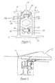
- Figure 1 is an end view of a first embodiment of a guide rail and chain support;
- Figure 2 is a perspective view of a guide rail in a panel gutter;
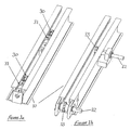
- Figures 3a and 3b show respectively a tension means and sprocket connection;
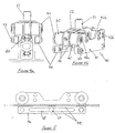
- Figures 4a and 4b show respectively an end view and a perspective view of a connection means;
- Figure 5 illustrates a guide block;
- Figure 6 is a perspective view of a pick up link;
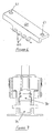
- Figure 7 is a second embodiment of a guide rail including a rack and pinion;
- Figures 8a-8d illustrate a chain tensioner incorporated into a carriage; and
- Figures 9a-9c show respectively a rear-drive system, a centre-drive system and a mid-drive system.
- The attached drawings show a system to enable a sunroof panel to be moved between an open and closed position. The system moreover provided is designed to be robust towards flexing of the panel and to minimise the noise produced during panel movement. The system is designed primarily for use within luxury boats. Typically such boats are of
length 15 to 30 metres and the panels under consideration approximately rectangular in shape and of dimension 2-4 metres. Such panels are designed to be relatively strong but lightweight and can be formed of plastics materials, glass fibre or carbon composites. - Referring initially to Figures 1 and 2, part of the mechanism for a control system is shown. A prime component is an
elongate guide rail 10, formed from aluminium or steel, which is set into a gutter orchannel 11 beneath aroof panel 12. Theguide rail 10 has a base plate 13. Twoside walls 14 depend perpendicularly upwardly, from the base plate 13 to define a U-shaped channel.Flanges side wall 14, and provide support for movement of thepanel 12. - In order to move the
panel 12, anendless chain 17 of typically ⅜" (0.95cm) pitch is provided, the chain being operably connected to a motor and to thepanel 12. Thechain 17 is located wholly within the U-shaped channel of theguide rail 10, and describes anupper path 18 and alower path 19 as part of a loop. Thelower path 19 of thechain 17 is supported by aridge 21 on alower chain guide 20. Resting on thelower chain guide 20 is anupper chain guide 22. Theupper chain guide 22 has afirst ridge 23 which depends downwardly from theupper chain guide 22, co-operating with theridge 21 to constrain lateral and vertical motion of thechain 17. - This feature reduces wear on the
chain 17, and also noise due to rattling of thechain 17. Moreover, impact of the boat's motion on the chain's motion is minimised. - A
second ridge 24 is also provided on theupper chain guide 22 to support thechain 17 as it moves along theupper path 18. To secure theupper chain guide 22 in position,ridges guide rail 10. - Further features of the system are shown in Figures 3a and 3b, which illustrate the tensioning block and the drive means. In order to minimise undesirable slack in the chain, tensioning means are provided. Two options for tensioning means are illustrated, which act in similar fashion. The tensioning means comprise an
idle sprocket 30 around which the chain (not shown in Figures 3a, 3b) passes. - The
sprocket 30 is connected to thetensioning block 31 whose operation enables the position of thesprocket 30 to be moved within theguide rail 10. By suitable adjustment of this position the effective path length of thechain 17 is altered. This feature facilitates installation of the system and also provides rapid correction if thechain 17 becomes slack after having been in use. The location of thesprocket 30 and thetensioning block 31 is at the discretion of the operator and depends upon compatibility with the particular boat in which the system is being used. - Motion of the
chain 17 is provided by a motor which connects through, via adrive shaft 32, to adrive sprocket 33 located within theguide rail 10. Figure 3a provides two options for the location of thetensioning block 31. Figure 3b shows two options for the location of thedrive sprocket 33, the choice of location depending upon the installation position of the motor. Thedrive sprocket 33 is supported by a block which supports thedrive shaft 32 and also provides clearance for a carriage (see below) to run over the elements of the tensioning means. - The
drive shaft 32 can be connected to the drive motor via universal joints and coupled shafts, although alternative connections such as flexible drive shafts can be used where suitable. - Motion of the
chain 17 is coupled to theroof panel 12 through acarriage 40 illustrated in Figures 4a, 4b and 5. Simply put, thecarriage 40 is connected to and supports thepanel 12 and thechain 17, and is itself supported on theguide rail 10. As the motor drives thechain 17 therefore, thecarriage 40 and thepanel 12 are moved along in the same direction. - The
carriage 40 has twocarriage brackets 41 to provide a support framework for the other carriage elements. At the front and rear of thecarriage 40 two rollers 42a, 42b are mounted onaxles axles brackets 41. Where suitable, the axles can be incorporated as an integral part of the rollers 42a, 42b. Each roller 42a, 42b is profiled by incorporation ofroller flanges 44. In use, the rollers surfaces 45 rest on the upper surface of theguide rail flanges roller flanges 44 are contiguous with the inwardly facing edges of theflanges flanges carriage 40 correctly aligned. - Each
bracket 41 also supports a generally elongatedblock 46 held in position on thebracket 41 by means of fixing means 47 passing through holes in thebracket 41 and into theblock 46. Theblock 46 is resilient in nature, resilience being provided firstly by the shape of theblock 46 having a cut awayportion 48 allowing the remainingportions 49 to flex. In an alternative embodiment, not illustrated, theblock 46 is formed of a resilient material. In use theblock 46 engages and is urged against the underside of the lower surface of theflange block 46 against theflange 15,16 apin 50 passes through theblock 46. - The roller surfaces 45 therefore co-operate with the
block 46 to restrict vertical movement of thecarriage 40. Such vertical movement may be occasioned by motion of the boat or engine vibrations. - The
carriage 40 is coupled to thepanel 12 by a connection system, simply illustrated as theconnection column 51. Theconnection column 51 is typically formed of a material such as to provide a strong member able to withstand the forces generated by the boat and the panel's movement. Aconnection bracket 52 supports and connects thecolumn 51 to thecarriage 40. In order to connect thecarriage 40 to thechain 17, a pick-up 60 (shown in Figure 6) is fixed to the lower portion of thecarriage 40 by fixing means which pass through theapertures 61. The pick-up 60 is provided withteeth 62 which sit between the links of thechain 17 and thereby couple thechain 17 to thecarriage 40. - In order to prevent ingress of dirt into the carriage or chain and to reduce the noise generated on operation of the system, a
brush pile 26 is located within the upperportion guide rail 10. The angle of thepile 26 is such that damaging engagement with theflanges 44 is avoided. - The
carriage 40 so described firmly connects thepanel 12 to theguide rail 10. Due to the elements of thecarriage 40, thepanel 12 is free to move in the direction of theguide rail 10 to open and cover an aperture. However, flexing of thepanel 12 is restricted so minimising the risk of thepanel 12 or the drive means detaching. - In Figure 7 a second embodiment of a system is shown. The carriage in Figure 7 is similar to that described above. The prime difference between the first and second embodiment is that the chain is replaced by a
rack 70 andpinion 71. - Figures 8a-8d illustrate alternative means of tensioning the
chain 17 in addition to or in conjunction with the means disclosed above. The tensioner 80 acts to ensure that the effective length of thechain 17 remains constant irrespective of the motion of the boat or thepanel 12 or of thermal expansion between the rail 13 and thechain 17. - A floating
housing 81 houses a series of springs 82-84, connected together in series. Thehousing pins springs chain 17.Further housing pins 83a, 83b connect thecentral spring 83 to thehousing 81, butting up against the downwardly depending wall of the floatinghousing 81. The incorporation of the tensioner 80 within the loop of thechain 17 itself ensures that the tension within thechain 17 remains relatively constant. Moreover, by suitable adjustment of the housings, the tension can be set to a desired value. - The motor to drive motion of the panel can be incorporated in a number of positions depending upon the particular boat in which the system is installed. In Figure 9a, the
motor 90 is mounted at the rear of the boat 91. Thepanel 12 is supported on twoguide rails 10 and driveshafts 92 link themotor 90 to thechain 17 within the guide rails 10. - Figure 9b illustrates a centre-drive option. Again the
motor 90 is mounted at the rear of the boat 91. The drive for thepanel 12 is however mounted solely in the central guide rail 93. Thepanel 12 is additionally supported by theside guide rail 94, but no drive mechanism is located within theside guide rail 94. - Figure 9c illustrates a mid-drive option. In this embodiment, the
motor 90 is mounted centrally with respect to the aperture. Thepanel 12 is supported by and the drive means located in eachside guide rail 94, withdrive shaft 92 linking the motor to thechain 17 with eachguide rail 94. - It will of course be understood that the invention is not limited to the specific details described herein, which are given by way of example only, and that various modifications and alterations are possible within the scope of the invention.
Claims (13)
- A sunroof system for a pleasure boat having a sliding roof panel (12) moveable between an open and a closed position the system including an endless chain (17) connected to a panel (12) by a carriage means;
a motor to drive the endless chain (17);
the chain (17) being constrained to run within a guide rail (10) having a base section, with side walls (14) depending therefrom to form a U-shaped channel, the free edge of each side wall (14) ending in a flange element (15, 16) orientated perpendicularly thereto and whereby the flange elements (15, 16) define a space therebetween, leaving the channel open along one surface,
the carriage means engaging and being supported by the surfaces of the flange element (15, 16). - A sunroof system according to Claim 1, characterised in that the system includes a chain guide located within the channel, the chain guide separating portions of the chain (17) moving in opposite directions.
- A system according to Claim 2, characterised in that the chain guide is in two sections to facilitate assembly.
- A system according to Claim 3, characterised in that the two sections are so profiled to provide one or more gaps between the sections along contacting surfaces.
- A system according to any preceding Claim, characterised in that the carriage means engages the flange elements by means of rollers.
- A system according to Claim 5, characterised in that the or each roller includes one or more flanges, engaging the edge of the flange elements.
- A system according to any preceding Claim, characterised in that the carriage means includes a block engaging the underside of a flange element and gripping the flange element between the block and a roller.
- A system according to Claim 7, characterised in that the block is formed of resilient material to dampen down vibrations.
- A system according to Claim 7, characterised in that the block includes resilient means.
- A system according to any one of Claims 7-9, characterised in that block is urged against the flange element by a pin or similar fixing means to ensure good contact.
- A system according to any preceding Claim, characterised in that the carriage means is operably connected to the chain by a toothed pick up, the teeth of the pick up sitting in the gaps between the links in the chain.
- A system according to any preceding Claim, characterised in that a brush pile is located in the guide rail to reduce noise and to hinder ingress of dirt into the rail which might cause damage.
- A system according to any preceding Claim, including tensioning means adjustable to remove slack from the chain.
Applications Claiming Priority (1)
| Application Number | Priority Date | Filing Date | Title |
|---|---|---|---|
| GB0618937A GB0618937D0 (en) | 2006-09-26 | 2006-09-26 | A sunroof system |
Publications (3)
| Publication Number | Publication Date |
|---|---|
| EP1908680A2 true EP1908680A2 (en) | 2008-04-09 |
| EP1908680A3 EP1908680A3 (en) | 2011-08-03 |
| EP1908680B1 EP1908680B1 (en) | 2012-11-21 |
Family
ID=37434683
Family Applications (1)
| Application Number | Title | Priority Date | Filing Date |
|---|---|---|---|
| EP20070253783 Active EP1908680B1 (en) | 2006-09-26 | 2007-09-25 | A sunroof system |
Country Status (2)
| Country | Link |
|---|---|
| EP (1) | EP1908680B1 (en) |
| GB (1) | GB0618937D0 (en) |
Cited By (4)
| Publication number | Priority date | Publication date | Assignee | Title |
|---|---|---|---|---|
| EP2161192A1 (en) * | 2008-09-08 | 2010-03-10 | Nautica Tender A/S | A boat with a shiftable roof |
| ITTO20090332A1 (en) * | 2009-04-28 | 2010-10-29 | Franco Tonini | LIFTING AND SLIDING MECHANISM NAUTICAL COVERS |
| GB2624396A (en) * | 2022-11-15 | 2024-05-22 | Trend Marine Products Ltd | Carriage and rail mounting assembly, e.g. for a sunroof on a boat |
| CN118419200A (en) * | 2024-07-05 | 2024-08-02 | 山东博新新材料有限公司 | Automatic tarpaulin for ship |
Family Cites Families (7)
| Publication number | Priority date | Publication date | Assignee | Title |
|---|---|---|---|---|
| FR1417270A (en) * | 1964-09-29 | 1965-11-12 | Boat deck cover | |
| WO1992004199A1 (en) * | 1990-09-10 | 1992-03-19 | Freddy Van Rie | Sliding window and sliding roof systems |
| US6533349B2 (en) * | 1998-07-27 | 2003-03-18 | Inalfa Industries B.V. | Open roof construction for a vehicle |
| DE19951619A1 (en) * | 1999-10-21 | 2001-04-26 | Michael Koch | Roof for motorboat is mounted on parallel arms to move into a raised sunshade or into a rear sun deck |
| DE602004000750T2 (en) * | 2004-01-23 | 2007-01-11 | Opac S.R.L. | Modular motion support system for a vehicle roof, in particular for a boat |
| ITTO20050563A1 (en) * | 2005-08-08 | 2007-02-09 | Azimut Benetti S P A | SUNSHADE UNIT-WINDSHIELD FOR BOATS |
| FR2892377B1 (en) * | 2005-10-24 | 2009-07-10 | Thibaut Jean Edouard Tincelin | RETRACTABLE PROTECTION OF AN EXTERIOR SHIP BRIDGE |
-
2006
- 2006-09-26 GB GB0618937A patent/GB0618937D0/en not_active Ceased
-
2007
- 2007-09-25 EP EP20070253783 patent/EP1908680B1/en active Active
Cited By (5)
| Publication number | Priority date | Publication date | Assignee | Title |
|---|---|---|---|---|
| EP2161192A1 (en) * | 2008-09-08 | 2010-03-10 | Nautica Tender A/S | A boat with a shiftable roof |
| WO2010026257A1 (en) * | 2008-09-08 | 2010-03-11 | Nautica Tender A/S | A boat with a shiftable roof |
| ITTO20090332A1 (en) * | 2009-04-28 | 2010-10-29 | Franco Tonini | LIFTING AND SLIDING MECHANISM NAUTICAL COVERS |
| GB2624396A (en) * | 2022-11-15 | 2024-05-22 | Trend Marine Products Ltd | Carriage and rail mounting assembly, e.g. for a sunroof on a boat |
| CN118419200A (en) * | 2024-07-05 | 2024-08-02 | 山东博新新材料有限公司 | Automatic tarpaulin for ship |
Also Published As
| Publication number | Publication date |
|---|---|
| EP1908680A3 (en) | 2011-08-03 |
| GB0618937D0 (en) | 2006-11-08 |
| EP1908680B1 (en) | 2012-11-21 |
Similar Documents
| Publication | Publication Date | Title |
|---|---|---|
| CN102431425B (en) | Sunroof device | |
| KR100806591B1 (en) | Support structure of curved glass and wind regulator | |
| EP2338716B1 (en) | Sunshade assembly and open roof construction provided therewith | |
| CN101780758B (en) | Sunroof system | |
| EP1908680B1 (en) | A sunroof system | |
| US20070214726A1 (en) | Adjustable window lifter | |
| US8240752B2 (en) | Holding structure of guide pipe of sunroof apparatus | |
| US20050231007A1 (en) | Sliding roof system | |
| EP1524183B1 (en) | A modular movement support system for an openable roof for a vehicle, in particular for a boat | |
| JP2007503540A (en) | Fixed gripping tool for window glass of automobile power window device | |
| CN101121378B (en) | Stop structure in the sunroof device | |
| US20110198892A1 (en) | Deflector mechanism for sunroof apparatus | |
| US6533349B2 (en) | Open roof construction for a vehicle | |
| CN1874907A (en) | Seal structure of door for automobile | |
| CN103625252A (en) | Sunroof apparatus | |
| JP4465000B2 (en) | Sunroof device | |
| EP3674118B1 (en) | Open roof construction for use in a vehicle | |
| CN1762731A (en) | Lid for slip cover system | |
| JP5227387B2 (en) | Guide rail mounting structure for sunroof equipment | |
| JP4460421B2 (en) | Guide frame structure in sunroof device | |
| JP4495569B2 (en) | Sunroof device | |
| CN101117091A (en) | Installation structure of the guide frame in the sunroof device | |
| JP2008254706A (en) | Window regulator | |
| JP6883200B2 (en) | Deflector device for vehicles | |
| JP4789153B2 (en) | Automatic door engine unit mounting structure and seamless, automatic door |
Legal Events
| Date | Code | Title | Description |
|---|---|---|---|
| PUAI | Public reference made under article 153(3) epc to a published international application that has entered the european phase |
Free format text: ORIGINAL CODE: 0009012 |
|
| AK | Designated contracting states |
Kind code of ref document: A2 Designated state(s): AT BE BG CH CY CZ DE DK EE ES FI FR GB GR HU IE IS IT LI LT LU LV MC MT NL PL PT RO SE SI SK TR |
|
| AX | Request for extension of the european patent |
Extension state: AL BA HR MK RS |
|
| PUAL | Search report despatched |
Free format text: ORIGINAL CODE: 0009013 |
|
| AK | Designated contracting states |
Kind code of ref document: A3 Designated state(s): AT BE BG CH CY CZ DE DK EE ES FI FR GB GR HU IE IS IT LI LT LU LV MC MT NL PL PT RO SE SI SK TR |
|
| AX | Request for extension of the european patent |
Extension state: AL BA HR MK RS |
|
| RIC1 | Information provided on ipc code assigned before grant |
Ipc: B63B 17/02 20060101AFI20110628BHEP |
|
| 17P | Request for examination filed |
Effective date: 20120202 |
|
| AKX | Designation fees paid |
Designated state(s): AT BE BG CH CY CZ DE DK EE ES FI FR GB GR HU IE IS IT LI LT LU LV MC MT NL PL PT RO SE SI SK TR |
|
| GRAP | Despatch of communication of intention to grant a patent |
Free format text: ORIGINAL CODE: EPIDOSNIGR1 |
|
| GRAS | Grant fee paid |
Free format text: ORIGINAL CODE: EPIDOSNIGR3 |
|
| GRAA | (expected) grant |
Free format text: ORIGINAL CODE: 0009210 |
|
| AK | Designated contracting states |
Kind code of ref document: B1 Designated state(s): AT BE BG CH CY CZ DE DK EE ES FI FR GB GR HU IE IS IT LI LT LU LV MC MT NL PL PT RO SE SI SK TR |
|
| REG | Reference to a national code |
Ref country code: GB Ref legal event code: FG4D |
|
| REG | Reference to a national code |
Ref country code: CH Ref legal event code: EP |
|
| REG | Reference to a national code |
Ref country code: AT Ref legal event code: REF Ref document number: 584922 Country of ref document: AT Kind code of ref document: T Effective date: 20121215 |
|
| REG | Reference to a national code |
Ref country code: IE Ref legal event code: FG4D |
|
| REG | Reference to a national code |
Ref country code: DE Ref legal event code: R096 Ref document number: 602007026799 Country of ref document: DE Effective date: 20130117 |
|
| REG | Reference to a national code |
Ref country code: NL Ref legal event code: VDEP Effective date: 20121121 |
|
| REG | Reference to a national code |
Ref country code: AT Ref legal event code: MK05 Ref document number: 584922 Country of ref document: AT Kind code of ref document: T Effective date: 20121121 |
|
| REG | Reference to a national code |
Ref country code: LT Ref legal event code: MG4D |
|
| PG25 | Lapsed in a contracting state [announced via postgrant information from national office to epo] |
Ref country code: ES Free format text: LAPSE BECAUSE OF FAILURE TO SUBMIT A TRANSLATION OF THE DESCRIPTION OR TO PAY THE FEE WITHIN THE PRESCRIBED TIME-LIMIT Effective date: 20130304 Ref country code: FI Free format text: LAPSE BECAUSE OF FAILURE TO SUBMIT A TRANSLATION OF THE DESCRIPTION OR TO PAY THE FEE WITHIN THE PRESCRIBED TIME-LIMIT Effective date: 20121121 Ref country code: LT Free format text: LAPSE BECAUSE OF FAILURE TO SUBMIT A TRANSLATION OF THE DESCRIPTION OR TO PAY THE FEE WITHIN THE PRESCRIBED TIME-LIMIT Effective date: 20121121 Ref country code: SE Free format text: LAPSE BECAUSE OF FAILURE TO SUBMIT A TRANSLATION OF THE DESCRIPTION OR TO PAY THE FEE WITHIN THE PRESCRIBED TIME-LIMIT Effective date: 20121121 |
|
| PG25 | Lapsed in a contracting state [announced via postgrant information from national office to epo] |
Ref country code: BE Free format text: LAPSE BECAUSE OF FAILURE TO SUBMIT A TRANSLATION OF THE DESCRIPTION OR TO PAY THE FEE WITHIN THE PRESCRIBED TIME-LIMIT Effective date: 20121121 Ref country code: GR Free format text: LAPSE BECAUSE OF FAILURE TO SUBMIT A TRANSLATION OF THE DESCRIPTION OR TO PAY THE FEE WITHIN THE PRESCRIBED TIME-LIMIT Effective date: 20130222 Ref country code: SI Free format text: LAPSE BECAUSE OF FAILURE TO SUBMIT A TRANSLATION OF THE DESCRIPTION OR TO PAY THE FEE WITHIN THE PRESCRIBED TIME-LIMIT Effective date: 20121121 Ref country code: PT Free format text: LAPSE BECAUSE OF FAILURE TO SUBMIT A TRANSLATION OF THE DESCRIPTION OR TO PAY THE FEE WITHIN THE PRESCRIBED TIME-LIMIT Effective date: 20130321 Ref country code: PL Free format text: LAPSE BECAUSE OF FAILURE TO SUBMIT A TRANSLATION OF THE DESCRIPTION OR TO PAY THE FEE WITHIN THE PRESCRIBED TIME-LIMIT Effective date: 20121121 Ref country code: LV Free format text: LAPSE BECAUSE OF FAILURE TO SUBMIT A TRANSLATION OF THE DESCRIPTION OR TO PAY THE FEE WITHIN THE PRESCRIBED TIME-LIMIT Effective date: 20121121 |
|
| PG25 | Lapsed in a contracting state [announced via postgrant information from national office to epo] |
Ref country code: AT Free format text: LAPSE BECAUSE OF FAILURE TO SUBMIT A TRANSLATION OF THE DESCRIPTION OR TO PAY THE FEE WITHIN THE PRESCRIBED TIME-LIMIT Effective date: 20121121 |
|
| PG25 | Lapsed in a contracting state [announced via postgrant information from national office to epo] |
Ref country code: SK Free format text: LAPSE BECAUSE OF FAILURE TO SUBMIT A TRANSLATION OF THE DESCRIPTION OR TO PAY THE FEE WITHIN THE PRESCRIBED TIME-LIMIT Effective date: 20121121 Ref country code: BG Free format text: LAPSE BECAUSE OF FAILURE TO SUBMIT A TRANSLATION OF THE DESCRIPTION OR TO PAY THE FEE WITHIN THE PRESCRIBED TIME-LIMIT Effective date: 20130221 Ref country code: CZ Free format text: LAPSE BECAUSE OF FAILURE TO SUBMIT A TRANSLATION OF THE DESCRIPTION OR TO PAY THE FEE WITHIN THE PRESCRIBED TIME-LIMIT Effective date: 20121121 Ref country code: DK Free format text: LAPSE BECAUSE OF FAILURE TO SUBMIT A TRANSLATION OF THE DESCRIPTION OR TO PAY THE FEE WITHIN THE PRESCRIBED TIME-LIMIT Effective date: 20121121 Ref country code: EE Free format text: LAPSE BECAUSE OF FAILURE TO SUBMIT A TRANSLATION OF THE DESCRIPTION OR TO PAY THE FEE WITHIN THE PRESCRIBED TIME-LIMIT Effective date: 20121121 |
|
| PG25 | Lapsed in a contracting state [announced via postgrant information from national office to epo] |
Ref country code: RO Free format text: LAPSE BECAUSE OF FAILURE TO SUBMIT A TRANSLATION OF THE DESCRIPTION OR TO PAY THE FEE WITHIN THE PRESCRIBED TIME-LIMIT Effective date: 20121121 Ref country code: NL Free format text: LAPSE BECAUSE OF FAILURE TO SUBMIT A TRANSLATION OF THE DESCRIPTION OR TO PAY THE FEE WITHIN THE PRESCRIBED TIME-LIMIT Effective date: 20121121 |
|
| PLBE | No opposition filed within time limit |
Free format text: ORIGINAL CODE: 0009261 |
|
| STAA | Information on the status of an ep patent application or granted ep patent |
Free format text: STATUS: NO OPPOSITION FILED WITHIN TIME LIMIT |
|
| 26N | No opposition filed |
Effective date: 20130822 |
|
| REG | Reference to a national code |
Ref country code: DE Ref legal event code: R097 Ref document number: 602007026799 Country of ref document: DE Effective date: 20130822 |
|
| PG25 | Lapsed in a contracting state [announced via postgrant information from national office to epo] |
Ref country code: MC Free format text: LAPSE BECAUSE OF FAILURE TO SUBMIT A TRANSLATION OF THE DESCRIPTION OR TO PAY THE FEE WITHIN THE PRESCRIBED TIME-LIMIT Effective date: 20121121 |
|
| REG | Reference to a national code |
Ref country code: CH Ref legal event code: PL |
|
| REG | Reference to a national code |
Ref country code: IE Ref legal event code: MM4A |
|
| PG25 | Lapsed in a contracting state [announced via postgrant information from national office to epo] |
Ref country code: CH Free format text: LAPSE BECAUSE OF NON-PAYMENT OF DUE FEES Effective date: 20130930 Ref country code: IE Free format text: LAPSE BECAUSE OF NON-PAYMENT OF DUE FEES Effective date: 20130925 Ref country code: LI Free format text: LAPSE BECAUSE OF NON-PAYMENT OF DUE FEES Effective date: 20130930 |
|
| REG | Reference to a national code |
Ref country code: GB Ref legal event code: 732E Free format text: REGISTERED BETWEEN 20150326 AND 20150401 |
|
| PG25 | Lapsed in a contracting state [announced via postgrant information from national office to epo] |
Ref country code: MT Free format text: LAPSE BECAUSE OF FAILURE TO SUBMIT A TRANSLATION OF THE DESCRIPTION OR TO PAY THE FEE WITHIN THE PRESCRIBED TIME-LIMIT Effective date: 20121121 Ref country code: CY Free format text: LAPSE BECAUSE OF FAILURE TO SUBMIT A TRANSLATION OF THE DESCRIPTION OR TO PAY THE FEE WITHIN THE PRESCRIBED TIME-LIMIT Effective date: 20121121 Ref country code: TR Free format text: LAPSE BECAUSE OF FAILURE TO SUBMIT A TRANSLATION OF THE DESCRIPTION OR TO PAY THE FEE WITHIN THE PRESCRIBED TIME-LIMIT Effective date: 20121121 |
|
| PG25 | Lapsed in a contracting state [announced via postgrant information from national office to epo] |
Ref country code: LU Free format text: LAPSE BECAUSE OF NON-PAYMENT OF DUE FEES Effective date: 20130925 Ref country code: HU Free format text: LAPSE BECAUSE OF FAILURE TO SUBMIT A TRANSLATION OF THE DESCRIPTION OR TO PAY THE FEE WITHIN THE PRESCRIBED TIME-LIMIT; INVALID AB INITIO Effective date: 20070925 |
|
| PG25 | Lapsed in a contracting state [announced via postgrant information from national office to epo] |
Ref country code: IS Free format text: LAPSE BECAUSE OF FAILURE TO SUBMIT A TRANSLATION OF THE DESCRIPTION OR TO PAY THE FEE WITHIN THE PRESCRIBED TIME-LIMIT Effective date: 20121121 |
|
| REG | Reference to a national code |
Ref country code: FR Ref legal event code: PLFP Year of fee payment: 10 |
|
| REG | Reference to a national code |
Ref country code: FR Ref legal event code: PLFP Year of fee payment: 11 |
|
| REG | Reference to a national code |
Ref country code: FR Ref legal event code: PLFP Year of fee payment: 12 |
|
| PGFP | Annual fee paid to national office [announced via postgrant information from national office to epo] |
Ref country code: FR Payment date: 20230922 Year of fee payment: 17 Ref country code: DE Payment date: 20230919 Year of fee payment: 17 |
|
| REG | Reference to a national code |
Ref country code: DE Ref legal event code: R119 Ref document number: 602007026799 Country of ref document: DE |
|
| PG25 | Lapsed in a contracting state [announced via postgrant information from national office to epo] |
Ref country code: DE Free format text: LAPSE BECAUSE OF NON-PAYMENT OF DUE FEES Effective date: 20250401 |
|
| PG25 | Lapsed in a contracting state [announced via postgrant information from national office to epo] |
Ref country code: FR Free format text: LAPSE BECAUSE OF NON-PAYMENT OF DUE FEES Effective date: 20240930 |
|
| PGFP | Annual fee paid to national office [announced via postgrant information from national office to epo] |
Ref country code: GB Payment date: 20250923 Year of fee payment: 19 |
|
| PGFP | Annual fee paid to national office [announced via postgrant information from national office to epo] |
Ref country code: IT Payment date: 20250930 Year of fee payment: 19 |