EP1908667A1 - Vorderblock eines Kraftfahrzeugs - Google Patents
Vorderblock eines Kraftfahrzeugs Download PDFInfo
- Publication number
- EP1908667A1 EP1908667A1 EP07291178A EP07291178A EP1908667A1 EP 1908667 A1 EP1908667 A1 EP 1908667A1 EP 07291178 A EP07291178 A EP 07291178A EP 07291178 A EP07291178 A EP 07291178A EP 1908667 A1 EP1908667 A1 EP 1908667A1
- Authority
- EP
- European Patent Office
- Prior art keywords
- group
- front block
- blank
- elements
- liner
- Prior art date
- Legal status (The legal status is an assumption and is not a legal conclusion. Google has not performed a legal analysis and makes no representation as to the accuracy of the status listed.)
- Granted
Links
Images

Classifications
-
- B—PERFORMING OPERATIONS; TRANSPORTING
- B62—LAND VEHICLES FOR TRAVELLING OTHERWISE THAN ON RAILS
- B62D—MOTOR VEHICLES; TRAILERS
- B62D25/00—Superstructure or monocoque structure sub-units; Parts or details thereof not otherwise provided for
- B62D25/08—Front or rear portions
- B62D25/10—Bonnets or lids, e.g. for trucks, tractors, busses, work vehicles
- B62D25/105—Bonnets or lids, e.g. for trucks, tractors, busses, work vehicles for motor cars
-
- B—PERFORMING OPERATIONS; TRANSPORTING
- B62—LAND VEHICLES FOR TRAVELLING OTHERWISE THAN ON RAILS
- B62D—MOTOR VEHICLES; TRAILERS
- B62D29/00—Superstructures, understructures, or sub-units thereof, characterised by the material thereof
- B62D29/001—Superstructures, understructures, or sub-units thereof, characterised by the material thereof characterised by combining metal and synthetic material
- B62D29/005—Superstructures, understructures, or sub-units thereof, characterised by the material thereof characterised by combining metal and synthetic material preformed metal and synthetic material elements being joined together, e.g. by adhesives
-
- B—PERFORMING OPERATIONS; TRANSPORTING
- B62—LAND VEHICLES FOR TRAVELLING OTHERWISE THAN ON RAILS
- B62D—MOTOR VEHICLES; TRAILERS
- B62D65/00—Designing, manufacturing, e.g. assembling, facilitating disassembly, or structurally modifying motor vehicles or trailers, not otherwise provided for
- B62D65/02—Joining sub-units or components to, or positioning sub-units or components with respect to, body shell or other sub-units or components
- B62D65/04—Joining preassembled modular units composed of sub-units performing diverse functions, e.g. engine and bonnet
Definitions
- FR-A-2,698,334 a front block of the aforementioned type comprising a one-piece shutter assembly in which the hood, the wings and the shield are movable jointly with respect to the body elements.
- the hood, the wings and the shield of the shutter assembly came from material.
- the aesthetic appearance of the front block is improved, since there is no variable game between these elements.
- an access hatch provided in the hood.
- the shutter assembly is moved in a single block relative to the body elements to access the engine.
- Such a front block does not give complete satisfaction. Indeed, in case of even minor impact on one of the aforementioned elements of the shutter assembly, it is necessary to replace the entire shutter assembly to repair the vehicle. The cost of repair is high, especially when the damage to the body is minor.
- An object of the invention is to obtain a front block comprising a shutter assembly of satisfactory aesthetic appearance, while being repairable at low cost.
- the subject of the invention is a front block of the aforementioned type, characterized in that each element of the group is reversibly dismountable relative to all the other elements of the group.
- orientations are the usual orientations of a motor vehicle.
- the terms “upper”, “lower”, “up”, “down”, “horizontal”, “vertical”, “transverse”, “longitudinal”, “forward”, “rear”, “left”, “right” means in relation to the normal direction of traffic of a vehicle and the position of a driver.
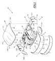
- a first front block 10 according to the invention is shown in Figures 1 to 4.
- the front block 10 comprises body elements 12, a motor compartment 14 delimited by the elements 12, a movable assembly 16 closing the engine compartment 14, and means 18 for articulating the closure assembly 16 with respect to the body elements 12.
- the body members 12 comprise two parallel side rails 20 connected at the front by a transverse structure 22, such as for example a front bumper beam.
- the longitudinal members 20 extend forward of an apron 24 separating the engine compartment 14 from the passenger compartment of the vehicle.
- the compartment 14 extends between the left and right longitudinal members 20, at the front of the deck 24, and at the rear of the structure 22. It contains a motor (not shown).
- the engine is placed at the rear of the vehicle and the body members 12 define at the front a storage compartment of objects.
- the transverse structure 22 is covered at the front and on the sides by a lower shield 25 fixed on the body elements 12.
- the shutter assembly 16 comprises a structural liner 26 and a group of body elements 28 fixed to the liner 26, movable jointly with the body members 12.
- the group of elements 28 is constituted by an upper cover 30, two lateral wings 32A, 32B, an upper front shield 34, and two projectors 36A, 36B inserted between the cover 30, the wings 32A, 32B and the shield 34.
- the shutter assembly 16 further comprises means 38 for releasably fixing the elements 28 relative to each other.
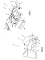
- the liner 26 is formed by a perforated framework 38 made of composite or hybrid material.
- the frame 38 comprises a substantially horizontal upper portion 40 and a front portion 42 extending substantially in a transverse vertical plane.
- the upper part 40 has a width, taken between its left upright 44A and its right upright 44B, substantially equal to that of the hood 30.
- the front portion 42 extends to the front of the upper portion 40, downward, to a lower transverse beam 46 which defines its lower edge.
- the frame 38 delimits, on the left and on the right, two lateral housings 48A, 48B for receiving the projectors 36A, 36B extending under the uprights 44A, 44B and above the beam 46.
- the upper cover 30 is fixed on the upper part 40 by means of the fastening means 38. It is made for example based on a sheet covered with paint. It comprises a rear region 50 of width substantially equal to the distance between the uprights 44A, 44B, and a front strip 52 extending downwards to seal an upper region of the front portion 42 of the liner.
- the rear region 50 defines a left edge 54A and a straight edge 54B extending adjacent to the wings 32A, 32B, when the members 28 are all attached to the liner 26.
- the strip 52 defines a front edge 56 extending adjacent to the upper shield 34 between the projectors 36A, 36B. It further comprises a left edge 58A and a straight edge 58B respectively extending along the projector 36A and the projector 36B.
- the cover 30 has, along its lateral edges 54A, 54B and its front edge 56, fixing blanks 60 visible in Figure 3 and intended to be engaged in the fastening means 38, as will be seen below.
- Each wing 32A, 32B extends downwardly from a side edge 54A, 54B of the hood.
- Each wing 32A, 32B defines a substantially horizontal upper edge 62, adjacent to a lateral edge 54A, 54B of the cover 30, and a lower edge 64 defining a wheel access opening.
- the wing 32A comprises, along its upper edge 62, a longitudinal attachment blank 66 intended to be inserted into the fastening means 38 against the blank 60 of the cover 30, as will be seen below.
- the upper shield 34 extends substantially vertically between an upper edge 68 and a lower edge 70 adjacent to the lower shield 25. It comprises a central region 72 transversely covering the front of the transverse structure 22 and two lateral cheeks 74 extending longitudinally under the projectors 36A, 36B to the left and to the right of the transverse structure 22.
- the upper edge 68 is adjacent to the front edge 56 of the strip 52 between the projectors 36A, 36B. It also extends under the projectors 36A, 36B adjacent to these projectors.
- the strip 34 comprises, along the edge 68, an upper fixing flank 75 intended to be inserted into the fixing means 38 against the lower cover fastening blank 60 extending along the front edge 56A.
- the projectors 36A, 36B are removably attached in the housings 48A, 48B on the frame 39. They are flush with the wings 32A, 32B at the rear, the hood 30 on the top, and the upper shield 34 below.
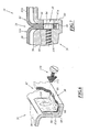
- the fastening means 38 comprise gutters 80 formed in the frame 38 along the uprights 44A, 44B, and along the beam 46.
- the means 38 comprise, for each gutter 80, at least one locking lug 82 intended to be inserted into complementary openings 84 formed in the fixing flanges 60, 66, 75 of the elements 28.
- the fixing means 38 further comprise indexing stops 86 of the blanks 60, 66, 75.
- Each channel 80 defines a slot 87 opening towards the outside of the vehicle and having a width slightly greater than the thickness of two blanks 60, 66 adjacent.
- the length of the gutters 80 is substantially equal to the length of the blanks 60, 66 which are inserted into the gutter 80.
- the latching tabs 82 are arranged projecting in the channel 80. They are integral with the side walls 87A forming the channel 80 and are movable relative to these walls 87A between an extended position of attachment and a retracted position of insertion of the blanks 60, 66. Each tab 82 is frangible when the element 28 receiving the tab 82 moves in the event of impact against the vehicle.
- the indexing abutments 86 comprise a bottom rib 90 disposed in the bottom of the trough 80 and two vertical ribs 92 disposed on the walls 87A opposite the trough 80.
- each element 28 of the closure assembly 16 of the group constituted by the upper cover 30, the lateral wings 32, the upper shield 34 and the projectors 36 is reversibly dismountable relative to all the others. elements 28 of this group.
- hood 30 and the wings 32A, 32B are movable relative to each other and relative to the lining 26 between a disassembled position shown in Figure 1 and an assembled position shown in Figure 2.
- each fixing flange 60 of the cover 30 has been introduced into a gutter 80 at the same time as the securing flange 66 of a flange 32A, 32B.
- the blanks 60, 66 are wedged between the vertical ribs 88, which ensures a substantially zero longitudinal clearance between the cover 30 and each wing 32A, 32B along each channel 80.
- the blanks 60, 66 are abutted against the bottom rib 90 which provides a flush between the exterior appearance surface of the hood 30 and the outer appearance surface of each wing 32A, 32B.
- Each latching lug 82 is inserted into the facing openings 84 formed in the fixing flange 60 of the cover 30 and in the fixing flange 66 of each flange 32A, 32B to hold the flanges 32A, 32B and the cover 30 in position. .
- each tab 82 has been extracted from the receiving openings 84 and the respective blanks 60, 66 have been removed from the channel 80.
- the hood 30 and the lower shield 34 are movable relative to each other and relative to the lining 26 between a disassembled position and an assembled position in which the fixing blank 60 located along the front edge 56 of the cover 30 and the attachment blank 75 located along the upper edge 68 of the upper shield 34 have been inserted into a channel 80 and are held in this channel 80 by latching tabs 82 similar to those shown in FIG. 2 .
- the projectors 36 are also removably attached to the liner 26.
- each element 28 of the group consisting of the cover 30, the wings 32A, 32B, the upper shield 34, and the projectors 36A, 36B is reversibly dismountable relative to all the other elements 28 of this group.
- the shutter assembly 16 is movable between a shutter configuration of the engine compartment 14 shown in solid lines in Figure 4, and a compartment access configuration. 14, shown in phantom in Figure 4, in which the closure assembly 16 has been pivoted forwards about a transverse axis passing substantially through the lower edge 70 of the shield 34, via the articulation means 18.
- the elements 28 of the group are integral with each other to be moved jointly with respect to the body members 12 between the closure configuration of the housing and the housing access configuration.
- the various elements of the group 28 are reported on the liner 26.
- the projectors 36A, 36B are screwed into the respective housings 48A, 48B.
- the fixing flanges 66 of the wings 32A, 32B are introduced into the gutters 80 together with the fixing blanks 60 situated along the left edge 54A and the right edge 54B of the cover 30, until the blanks 60, 66 abut against the bottom ribs 90.
- the latching tabs 82 penetrate into the complementary openings 84 for reversibly holding the wings 32A, 32B and the hood 30 on the liner 26.
- the fixing blanks 60, 75 located respectively along the front edge 56A of the cover 30 and along the upper edge 68 of the shield 34 are introduced together into the channel 80 formed in the beam lower transverse 46 and are held by snapping inside the gutter.
- the clearance between these elements is substantially zero because of the wedging of the blanks 60, 66 between the vertical ribs 92 indexing stops 86.
- the upper surfaces d aspect of the hood 30 and side wings 32A, 32B are flush, as well as the front surfaces of the strip 52 and the shield 34.
- the closure assembly 16 thus has a very satisfactory aesthetic appearance.
- the wing 32A is disassembled with respect to the lining 26 and with respect to each of the other elements 28 of the shutter assembly 16
- the fixing flange 66 of the flange 32A is extracted out of the channel 80 by disengaging each detent tab 82 from the openings 84.
- the integrity of the adjacent element 28, in this example the hood 30, is preserved.
- the disassembly of the wing 32A is therefore perfectly reversible since this damaged wing 32A can be replaced by an identical wing 32A, without the need to replace the cover 30 or another element 28. It is therefore possible to greatly reduce the repair costs of such a shutter assembly 16, without harming the aesthetic appearance of the vehicle.
- the gutters 80 are not formed in the frame 39 of the liner 26.
- Pressure elements 99 are attached to the liner 26 along the uprights 44A, 44B and in front of the lower beam 46.
- the gutters 80 are formed in these pressing elements 99.
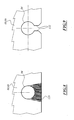
- the fastening means 38 comprises a quarter-turn fixing screw 110.
- the screw 110 comprises a free end 112 of width greater than its thickness.
- the walls 87A opposite the gutter 80 define openings vertical 114 wider than the thickness of the free end 112 of the screw 110, but less than the width of the free end 112.
- the openings 114 extend opposite the complementary openings 84 of the fastening blanks 60, 66 of the elements 28, when these blanks 60, 66 are introduced into the channel 80.
- a quarter turn screw 110 is provided for each receiving opening 84 formed in the blanks 60, 66. Then, the screw 110 is introduced through the openings 114 and the openings 84. complementary before being turned a quarter of a turn to ensure the reversible locking of the fixing blanks 60, 66 in the gutters 80.
- a self-tapping screw 116 is fixed in the walls 87A facing the channel 80 while engaging in the openings 84.
- a nut is attached to the rear of one of the walls 87A delimiting the channel 80.
- the screw 116 is inserted into this nut.
- each blank 60, 66 located under each opening 84 complementary, between the opening 84 and the free edge of the blank 60, 66 is frangible. It thus has a lower mechanical strength than the other regions surrounding the opening 84. Thus, in the event of impact against the element 28 having this frangible region 120, the fastener 110, 116 tears the region 120 to release the Element 28.
- each opening 84 is extended downwardly by a passage 122 opening through the free edge on the bottom of the trough 80.
- the passage 122 has a width smaller than that of the opening 84 and to that of the screwing member 110, 114.
Landscapes
- Engineering & Computer Science (AREA)
- Chemical & Material Sciences (AREA)
- Combustion & Propulsion (AREA)
- Transportation (AREA)
- Mechanical Engineering (AREA)
- Architecture (AREA)
- Structural Engineering (AREA)
- Manufacturing & Machinery (AREA)
- Body Structure For Vehicles (AREA)
- Superstructure Of Vehicle (AREA)
Applications Claiming Priority (1)
| Application Number | Priority Date | Filing Date | Title |
|---|---|---|---|
| FR0608708A FR2906782B1 (fr) | 2006-10-04 | 2006-10-04 | Bloc avant de vehicule automobile |
Publications (2)
| Publication Number | Publication Date |
|---|---|
| EP1908667A1 true EP1908667A1 (de) | 2008-04-09 |
| EP1908667B1 EP1908667B1 (de) | 2009-07-29 |
Family
ID=37873240
Family Applications (1)
| Application Number | Title | Priority Date | Filing Date |
|---|---|---|---|
| EP07291178A Ceased EP1908667B1 (de) | 2006-10-04 | 2007-09-28 | Vorderblock eines Kraftfahrzeugs |
Country Status (3)
| Country | Link |
|---|---|
| EP (1) | EP1908667B1 (de) |
| DE (1) | DE602007001756D1 (de) |
| FR (1) | FR2906782B1 (de) |
Cited By (2)
| Publication number | Priority date | Publication date | Assignee | Title |
|---|---|---|---|---|
| FR3109356A1 (fr) * | 2020-04-16 | 2021-10-22 | Psa Automobiles Sa | Capot de véhicule automobile avec extensions latérales |
| US20240208454A1 (en) * | 2018-01-26 | 2024-06-27 | Sabic Global Technologies B.V. | Front end panel assembly for an electric vehicle |
Citations (2)
| Publication number | Priority date | Publication date | Assignee | Title |
|---|---|---|---|---|
| FR2698334A1 (fr) * | 1992-11-20 | 1994-05-27 | Peugeot | Agencement de véhicule automobile comportant un élément unique antérieur de carrosserie en forme de coquille. |
| EP1666313A1 (de) * | 2003-01-10 | 2006-06-07 | C.R.F. Società Consortile per Azioni | Fahrzeug mit einem bewegbaren Vorderteil, insbesondere für die Sicherheit von Fussgängern im Fall eines Unfalles |
-
2006
- 2006-10-04 FR FR0608708A patent/FR2906782B1/fr not_active Expired - Fee Related
-
2007
- 2007-09-28 DE DE602007001756T patent/DE602007001756D1/de active Active
- 2007-09-28 EP EP07291178A patent/EP1908667B1/de not_active Ceased
Patent Citations (2)
| Publication number | Priority date | Publication date | Assignee | Title |
|---|---|---|---|---|
| FR2698334A1 (fr) * | 1992-11-20 | 1994-05-27 | Peugeot | Agencement de véhicule automobile comportant un élément unique antérieur de carrosserie en forme de coquille. |
| EP1666313A1 (de) * | 2003-01-10 | 2006-06-07 | C.R.F. Società Consortile per Azioni | Fahrzeug mit einem bewegbaren Vorderteil, insbesondere für die Sicherheit von Fussgängern im Fall eines Unfalles |
Cited By (3)
| Publication number | Priority date | Publication date | Assignee | Title |
|---|---|---|---|---|
| US20240208454A1 (en) * | 2018-01-26 | 2024-06-27 | Sabic Global Technologies B.V. | Front end panel assembly for an electric vehicle |
| US12311868B2 (en) * | 2018-01-26 | 2025-05-27 | Sabic Global Technologies B.V. | Front end panel assembly for an electric vehicle |
| FR3109356A1 (fr) * | 2020-04-16 | 2021-10-22 | Psa Automobiles Sa | Capot de véhicule automobile avec extensions latérales |
Also Published As
| Publication number | Publication date |
|---|---|
| DE602007001756D1 (de) | 2009-09-10 |
| FR2906782A1 (fr) | 2008-04-11 |
| FR2906782B1 (fr) | 2009-01-23 |
| EP1908667B1 (de) | 2009-07-29 |
Similar Documents
| Publication | Publication Date | Title |
|---|---|---|
| EP2512850B1 (de) | Heckklappe eines kraftfahrzeuges | |
| EP0970854B1 (de) | Vorrichtung zur Befestigung der Seitenschenkel einer Stossstange auf einem Fahrzeugkarosserie-Kotflügel | |
| EP1403174B1 (de) | Frontteil für Motorhaube | |
| FR3041905A1 (fr) | Dispositif vitre affleurant pour porte de vehicule, porte, vehicule automobile, procede de fabrication et dispositif d'etancheite correspondants. | |
| EP3592631B1 (de) | Anordnung zum halten eines gepäckraumbehälters an der vorderseite einer kraftfahrzeugkarosseriestruktur | |
| EP3119634B1 (de) | Zusammenbau einer luftführung mit einem strukturelement eines kraftfahrzeugs und zugehöriges fahrzeug | |
| EP1908667B1 (de) | Vorderblock eines Kraftfahrzeugs | |
| EP1530273B1 (de) | Winkelzubehörelement für Führungskanäle mit zwei in die Quere zusammengefügten Flügeln | |
| WO2017203120A1 (fr) | Doublure interne de volet arrière | |
| FR2915952A1 (fr) | Ensemble d'extremite de vehicule automobile, procede de montage et vehicule automobile associe. | |
| EP0169747A1 (de) | Stossdämpfer für Fahrzeug | |
| FR2664546A1 (fr) | Cellule isotherme demontable pour fourgonnette. | |
| FR3113297A1 (fr) | Coffre de volet roulant équipé d’une structure longitudinale de renfort intérieure | |
| EP1923270A1 (de) | Verdeckeinheit für Kraftfahrzeugdach und entsprechendes Kraftfahrzeug | |
| EP3007935B1 (de) | Kunststoffverkleidung zum befestigen auf einem unterteil der innenfläche der heckklappe eines kraftfahrzeugs | |
| FR3009708A1 (fr) | Sous-ensemble de cote de caisse de vehicule | |
| EP2065261A1 (de) | Stoßstangenhaut für ein Frontmodul eines Kraftfahrzeugs und zugehöriges Kraftfahrzeug | |
| FR2994913A1 (fr) | Habillage de paroi laterale d'un coffre de vehicule automobile et vehicule correspondant | |
| FR2917036A1 (fr) | Ensemble d'extremite de vehicule automobile comprenant un absorbeur pre-positionne. | |
| FR3075245A1 (fr) | Agencement d'une porte a panneau, coupe-feu, avec inserts de fixation et de centrage | |
| FR2917035A1 (fr) | Ensemble d'extremite de vehicule automobile comprenant un absorbeur a lames elastiques. | |
| FR2828853A1 (fr) | Plaque rigide d'habillage d'une marche et marchepied pourvu de cette plaque | |
| EP1637378B1 (de) | Einbaueinheit mit abnehmbaren Dachdeckel und abnehmbaren Windabweiser für KFZ-Dächer | |
| WO2024126911A1 (fr) | Enjoliveur de hayon de véhicule automobile | |
| FR2781616A1 (fr) | Boite d'encastrement susceptible d'etre jumelee avec une autre, notamment pour appareillage electrique |
Legal Events
| Date | Code | Title | Description |
|---|---|---|---|
| PUAI | Public reference made under article 153(3) epc to a published international application that has entered the european phase |
Free format text: ORIGINAL CODE: 0009012 |
|
| AK | Designated contracting states |
Kind code of ref document: A1 Designated state(s): AT BE BG CH CY CZ DE DK EE ES FI FR GB GR HU IE IS IT LI LT LU LV MC MT NL PL PT RO SE SI SK TR |
|
| AX | Request for extension of the european patent |
Extension state: AL BA HR MK RS |
|
| 17P | Request for examination filed |
Effective date: 20080930 |
|
| 17Q | First examination report despatched |
Effective date: 20081031 |
|
| AKX | Designation fees paid |
Designated state(s): DE FR |
|
| GRAP | Despatch of communication of intention to grant a patent |
Free format text: ORIGINAL CODE: EPIDOSNIGR1 |
|
| GRAS | Grant fee paid |
Free format text: ORIGINAL CODE: EPIDOSNIGR3 |
|
| GRAA | (expected) grant |
Free format text: ORIGINAL CODE: 0009210 |
|
| AK | Designated contracting states |
Kind code of ref document: B1 Designated state(s): DE FR |
|
| REF | Corresponds to: |
Ref document number: 602007001756 Country of ref document: DE Date of ref document: 20090910 Kind code of ref document: P |
|
| PLBE | No opposition filed within time limit |
Free format text: ORIGINAL CODE: 0009261 |
|
| STAA | Information on the status of an ep patent application or granted ep patent |
Free format text: STATUS: NO OPPOSITION FILED WITHIN TIME LIMIT |
|
| 26N | No opposition filed |
Effective date: 20100503 |
|
| REG | Reference to a national code |
Ref country code: FR Ref legal event code: PLFP Year of fee payment: 10 |
|
| REG | Reference to a national code |
Ref country code: FR Ref legal event code: PLFP Year of fee payment: 11 |
|
| PGFP | Annual fee paid to national office [announced via postgrant information from national office to epo] |
Ref country code: DE Payment date: 20170821 Year of fee payment: 11 Ref country code: FR Payment date: 20170822 Year of fee payment: 11 |
|
| REG | Reference to a national code |
Ref country code: DE Ref legal event code: R119 Ref document number: 602007001756 Country of ref document: DE |
|
| PG25 | Lapsed in a contracting state [announced via postgrant information from national office to epo] |
Ref country code: DE Free format text: LAPSE BECAUSE OF NON-PAYMENT OF DUE FEES Effective date: 20190402 |
|
| PG25 | Lapsed in a contracting state [announced via postgrant information from national office to epo] |
Ref country code: FR Free format text: LAPSE BECAUSE OF NON-PAYMENT OF DUE FEES Effective date: 20180930 |