EP1530273B1 - Winkelzubehörelement für Führungskanäle mit zwei in die Quere zusammengefügten Flügeln - Google Patents
Winkelzubehörelement für Führungskanäle mit zwei in die Quere zusammengefügten Flügeln Download PDFInfo
- Publication number
- EP1530273B1 EP1530273B1 EP04292441A EP04292441A EP1530273B1 EP 1530273 B1 EP1530273 B1 EP 1530273B1 EP 04292441 A EP04292441 A EP 04292441A EP 04292441 A EP04292441 A EP 04292441A EP 1530273 B1 EP1530273 B1 EP 1530273B1
- Authority
- EP
- European Patent Office
- Prior art keywords
- flap
- engagement elements
- angle accessory
- male
- male engagement
- Prior art date
- Legal status (The legal status is an assumption and is not a legal conclusion. Google has not performed a legal analysis and makes no representation as to the accuracy of the status listed.)
- Expired - Lifetime
Links
- 239000000463 material Substances 0.000 claims description 9
- 239000002991 molded plastic Substances 0.000 claims 3
- 210000002445 nipple Anatomy 0.000 description 7
- 238000000465 moulding Methods 0.000 description 6
- 230000035939 shock Effects 0.000 description 5
- 210000005069 ears Anatomy 0.000 description 4
- 230000015572 biosynthetic process Effects 0.000 description 3
- 239000011324 bead Substances 0.000 description 1
- 239000004020 conductor Substances 0.000 description 1
- 238000003780 insertion Methods 0.000 description 1
- 230000037431 insertion Effects 0.000 description 1
- 238000005192 partition Methods 0.000 description 1
Images
Classifications
-
- H—ELECTRICITY
- H02—GENERATION; CONVERSION OR DISTRIBUTION OF ELECTRIC POWER
- H02G—INSTALLATION OF ELECTRIC CABLES OR LINES, OR OF COMBINED OPTICAL AND ELECTRIC CABLES OR LINES
- H02G3/00—Installations of electric cables or lines or protective tubing therefor in or on buildings, equivalent structures or vehicles
- H02G3/02—Details
- H02G3/06—Joints for connecting lengths of protective tubing or channels, to each other or to casings, e.g. to distribution boxes; Ensuring electrical continuity in the joint
- H02G3/0608—Joints for connecting non cylindrical conduits, e.g. channels
-
- H—ELECTRICITY
- H02—GENERATION; CONVERSION OR DISTRIBUTION OF ELECTRIC POWER
- H02G—INSTALLATION OF ELECTRIC CABLES OR LINES, OR OF COMBINED OPTICAL AND ELECTRIC CABLES OR LINES
- H02G3/00—Installations of electric cables or lines or protective tubing therefor in or on buildings, equivalent structures or vehicles
- H02G3/02—Details
- H02G3/04—Protective tubing or conduits, e.g. cable ladders or cable troughs
- H02G3/0425—Plinths
-
- F—MECHANICAL ENGINEERING; LIGHTING; HEATING; WEAPONS; BLASTING
- F16—ENGINEERING ELEMENTS AND UNITS; GENERAL MEASURES FOR PRODUCING AND MAINTAINING EFFECTIVE FUNCTIONING OF MACHINES OR INSTALLATIONS; THERMAL INSULATION IN GENERAL
- F16B—DEVICES FOR FASTENING OR SECURING CONSTRUCTIONAL ELEMENTS OR MACHINE PARTS TOGETHER, e.g. NAILS, BOLTS, CIRCLIPS, CLAMPS, CLIPS OR WEDGES; JOINTS OR JOINTING
- F16B2200/00—Constructional details of connections not covered for in other groups of this subclass
- F16B2200/67—Rigid angle couplings
-
- Y—GENERAL TAGGING OF NEW TECHNOLOGICAL DEVELOPMENTS; GENERAL TAGGING OF CROSS-SECTIONAL TECHNOLOGIES SPANNING OVER SEVERAL SECTIONS OF THE IPC; TECHNICAL SUBJECTS COVERED BY FORMER USPC CROSS-REFERENCE ART COLLECTIONS [XRACs] AND DIGESTS
- Y10—TECHNICAL SUBJECTS COVERED BY FORMER USPC
- Y10T—TECHNICAL SUBJECTS COVERED BY FORMER US CLASSIFICATION
- Y10T403/00—Joints and connections
- Y10T403/32—Articulated members
Definitions
- the present invention generally relates to chutes of the type of those used, for example, for the support, housing and protection of conductors, pipes or other equipment necessary for the service of these devices.
- an angle accessory intended to establish a continuity between two chute sections running on two walls forming a dihedral between them, comprising two separate flaps having assembly means which cooperate to allow the pivoting of said flaps around. a pivot axis, these assembly means comprising, on the one hand, at a return end of the first flap, two male engagement elements extending along the pivot axis, and, on the other hand, at a return end of the second flap, two female engagement members for receiving said engagement members
- a flap comprises at one end of its returns ears facing each other which carry pins for insertion into openings provided in the returns of the other flap.
- the assembly of the flaps between them is achieved by slightly pinching the returns of the flap carrying said openings to elastically deform said returns and engage said openings on said nipples.
- said flaps can take different relative angular positions between a first extreme position in which the flap carrying the nipples maximally discovers the other flap to form an angle less than or equal to 90 ° and a second extreme position in which the flap carrying the nipples are completely folded on the other flap to form an angle greater than 90 °.
- each of said ears carrying the nipples of the corresponding flap has a circular edge provided with a bevel which, when said flap is in the second extreme position completely folded on the other flap, is intended to cooperate with a wedge provided hollow in the vicinity of the opening, on the outer surface of the return of the corresponding flap.
- This cooperation of the bevels with the corners prevents that, in this second extreme position, a shock intervening on said flaps causes the exit of the nipples of said openings and thus the disassembly of said flaps.
- the major disadvantage of the aforementioned corner accessory is that, apart from this arrangement of bevels and corners, it has no means to prevent, in the relative angular positions of said flaps other than said second extreme position mentioned above, a shock intervening on said flaps causes the exit of the nipples of said openings and thus the disassembly of said flaps.
- the present invention proposes an accessory as defined in the introduction which comprises a means to prevent a shock occurring on said flaps causes the disassembly of said flaps regardless of their relative position. use.
- the corner accessory according to the invention is characterized in that the first flap carries, in the vicinity of said male engagement elements, projecting from one of its end edges, at least one wing which forms an obstacle defining with at least one return of said first flap at least one access passage to at least one male engagement element, said passage having a reduced height constraining to assemble said flaps together by approaching the second flap inclined with respect to the pivot axis of the first flap, then pivoting said second flap to straighten it along the axis of pivoting so as successively to engage one of said female engagement elements on the corresponding male engagement element and then the other of said female engagement members on the other corresponding male engagement member.
- an angle accessory 100 according to the invention to be arranged at the junction of two chutes 10, 20 of different orientations.
- this corner accessory 100 is particularly suitable for joining two troughs 10, 20 making, in practice, a right angle between them.
- the bases 11, 21 of the two troughs 10, 20 are each respectively arranged flat on these two walls, for example running in baseboard at the base thereof.
- the ends of the pedestals 11, 21 of the chutes 10, 20 are cut substantially contiguously at their bottom and are positioned edge to edge, in a substantially contiguous manner, to form substantially the projecting angle formed by the support walls between them. .
- the bases 11, 21 of the troughs 10, 20 have a generally U-shaped cross section with two lateral wings which border a bottom.
- the base 11, 21 of each chute 10, 20 carries a partition wall which rises perpendicularly to its bottom to separate the interior space of said base in two compartments isolated from one another.
- Each base 11, 21 of each chute 10, 20 is closed by a cover 12, 22 which is adapted to be attached by snapping on the lateral wings of said base 11, 21.
- the covers 12, 22 are said to cover because they cover the outer face of said lateral wings.
- the corner accessory 100 is a cover which locally replaces the cover 12, 22 of each of the troughs, preferably covering the corresponding cut end of this cover (see FIG. figure 4 ).
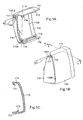
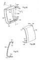
- Each flap 110, 120 has a profile similar to that of the covers 12, 22 of the troughs 10, 20, with a cheek lined on two opposite sides of two returns 111, 112, 121, 122 extending vis-a-vis substantially to the square of said cheek.
- each flap 110, 120 comprise, on the side of the inner face 110A, 120A of the cheek, securing means 113, 123 which are adapted to maintain the flap 110, 120 relative to the troughs 10, 20.
- these securing means are snap teeth 113, 123 adapted to snap on snap-on beads (not visible on the figure 4 ) located on the outer face of said lateral wings of the bases 11, 21 of said troughs 10, 20.
- each flap 110, 120 has an end portion (consisting of a portion of the cheek and two returns of the flap), said outer end portion (located on the right on the Figure 1A for the first flap 110 and left on the Figure 2A for the second flap 120) adapted to cover a cut end portion of the cover 12, 22 corresponding chute.
- each flap 110, 120 has on its inner face 110A, 120A, at the junction between the ratchet teeth 113, 123 and said outer end portion, a flange or abutment which extends on the cheek of the flap 110, 120 and which serves as a positioning mark of each flap 110, 120 on each cover 12, 22 trough bearing against the cut edge of the corresponding cover 12, 22.
- the flaps 110, 120 of the corner accessory 100 comprise assembly means which cooperate to allow the pivoting of said flaps 110, 120 around a pivot axis X.
- These assembly means comprise, on the one hand, at one end of the returns 111, 112 of the first flap 110, two male engagement elements 114, 115 extending along the pivot axis X (see Figures 1A, 1B ), and, on the other hand, at one end of the returns 121, 122 of the second flap 120, two female engagement elements 124, 124A, 125, 125A for receiving said male engagement elements 114, 115 (see Figure 2A, 2B ).
- the two male engagement elements 114, 115 are located at the so-called inner end (located on the left on the Figure 1A ) returns 111, 112 of the first flap 110, that is to say the opposite of said outer end adapted to cover an end portion of a chute cover 12.
- the two female engagement members 124, 124A, 125, 125A are located at the so-called inner end (located to the right on the Figure 2A ) returns 121, 122 of the second flap 120, that is to say the opposite of said outer end adapted to cover an end portion of a chute cover 22.
- said male engagement elements are pins 114, 115 which protrude from the inner face 110A of said first flap 110. Said pins 114, 115 face each other and define the axis of rotation X (see Figure 1 A) .
- Said female engagement elements are openings 124A, 125A provided in ears 124, 125 vis-à-vis protruding from the corresponding end edge 120B of said second flap 120.
- Said openings 124A, 125A are here circular, they are placed next to each other and therefore have the same Y axis (see Figure 2A ).
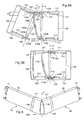
- the first flap 110 carries, in the vicinity of said male engagement elements 114, 115, projecting from one of its end edges 110B, at least one flange 116 which forms an obstacle defining with at least one return 111, 112 said first flap 110 at least one passage 117 for access to at least one male engagement element 114, said passage 117 having a reduced height H constraining to assemble said flaps 110, 120 between them by approaching the second flap 120 inclined relative to the pivot axis X of the first flap 110 (see figure 3A ), then pivoting said second flap 120 to straighten it along the pivot axis X (see figure 3B ) to successively engage one of said female engagement members 124, 124A on the corresponding male engagement member 114 and then the other of said female engagement members 125, 125A on the other corresponding male engagement member 115 .
- said wing 116 is unique and extends over most of the height of the first flap 110.
- This single flange 116 then defines two passages one for each ear 124, 125 of the second flap 120.
- a first passage 117 of reduced height H is defined between the upper edge 116A of said flange 116 and the return 111 of the first flap 110 and a second passage of reduced height H 'is defined between the lower edge 116B of said flange 116 and the return 112 of the first flap 110.
- the first passage 117 said upper passage, allows the opening 124A provided in the ear 124 of the second flap 120 to access the pin 114 of the first flap 110, and the second passage (not referenced on the figure 3A ), said lower passage, allows the opening 125A provided in the lug 125 of the second flap 120 to access the lug 115 of the first flap 110.
- the height of these passages 117 is approximately between 1 and 6 mm for example, preferably between 1 and 3 mm.
- This flange 116 preferably has a curved profile and is slightly inclined relative to the pivot axis X defined by said male engagement means 114, 115.
- the flange 116 establishes the junction between them by closing the angle formed by the chute bases 11, 21.
- said flange 116 forms a single piece with said first flap 110 made by molding a plastic material.
- one of the male engagement elements, the pin 115 has a slope 115A intended to cooperate with a chamfer 125B provided on the corresponding female engagement element, that is to say on the edge of the ear 125, to help assemble said male and female engagement members (see Figure 3A and 3B ).
- said male engagement elements 114, 115 and females 124, 124A, 125, 125A are formed respectively with said first flap 110 and said second flap 120, made by molding a plastic material.
- each flap 110, 120 of the corner accessory 100 is a monobloc piece preferably made by molding a plastic material.
- the second flap 120 is straightened along the pivot axis X to first engage said opening 124A on said pin 114, then insert the lower lug 125 in the corresponding passage defined between the flange 116 and the return 112 of the first flap 110 so that said opening 125A engages on the corresponding lug 115.
- This engagement of the opening 125A on the pin 115 is facilitated by the sliding of the chamfer 125B of the ear 125 on the slope 115A of said pin 115 which assists said pin 125 to overlap said pin 115.
- a shock intervening on said angle accessory 100 can then cause the disassembly of the two flaps 110, 120, regardless of the relative angular position of said flaps 110, 120, because it is easily understood that said second flap 120 can not of him even during a relatively violent shock, make the rearward pivoting movement out of its pivotal cooperation with said first flap 110.
- the opening 124A of the upper ear 124 could in no way out of its cooperation with the pin 114 because said ear 124 would naturally abut against the wing 116.
Landscapes
- Architecture (AREA)
- Civil Engineering (AREA)
- Structural Engineering (AREA)
- Engineering & Computer Science (AREA)
- Buckles (AREA)
- Measuring Volume Flow (AREA)
- Air-Flow Control Members (AREA)
- Operating, Guiding And Securing Of Roll- Type Closing Members (AREA)
- Electrochromic Elements, Electrophoresis, Or Variable Reflection Or Absorption Elements (AREA)
- Details Of Indoor Wiring (AREA)
- Joints Allowing Movement (AREA)
- Rigid Pipes And Flexible Pipes (AREA)
- Quick-Acting Or Multi-Walled Pipe Joints (AREA)
- Toys (AREA)
Claims (10)
- Winkelzubehörelement (100), das dazu bestimmt ist, eine Kontinuität zwischen zwei Führungskanalabschnitten (10, 20) herzustellen, die an zwei Wänden verlaufen und zwischen sich ein Zweiflach bilden, wobei das Winkelzubehörelement zwei einzelne Flügel (110, 120) umfasst, die Montagemittel darstellen, die zusammenwirken, um das Schwenken der Flügel um eine Schwenkachse (X) zu gestatten, und einerseits an einem Ende von Umbiegungen (111, 112) des ersten Flügels (110) zwei Eingriffselemente (114, 115), die sich entlang der Schwenkachse (X) erstrecken, und andererseits an einem Ende von Umbiegungen (121, 122) des zweiten Flügels (120) zwei Aufnahmeelemente (124, 124A, 125, 125A) umfassen, die dazu bestimmt sind, die Eingriffselemente (114, 115) aufzunehmen, dadurch gekennzeichnet, dass der erste Flügel (110) in der Nähe der Eingriffselemente (114, 115) und von einem seiner Endränder (110B) vorragend mindestens einen Schenkel (116) trägt, der ein Hindernis bildet, das mit mindestens einer Umbiegung (111) des ersten Flügels (110) mindestens einen Durchgang (117) definiert, für den Zugriff auf mindestens ein Eingriffselement (114), wobei der Durchgang (117) eine geringe Höhe (H) aufweist, wodurch man dazu gezwungen ist, die Flügel (110, 120) aneinander zu montieren, indem der zweite Flügel (120) bezüglich der Schwenkachse (X) des ersten Flügels (110) geneigt herangeführt wird und anschließend der zweite Flügel (120) geschwenkt wird, so dass er gemäß der Schwenkachse (X) ausgerichtet ist, um nacheinander eines der Eingriffselemente (124A) mit dem entsprechenden Eingriffselement (114) und dann das andere der Eingriffselemente (125A) mit dem entsprechenden anderen Eingriffselement (115) in Eingriff zu bringen.
- Winkelzubehörelement (100) nach Anspruch 1, dadurch gekennzeichnet, dass der Schenkel (116) einteilig ist und sich über den größten Teil der Höhe des entsprechenden Flügels erstreckt.
- Winkelzubehörelement (100) nach Anspruch 1 oder 2, dadurch gekennzeichnet, dass jeder Schenkel (116) ein gebogenes Profil hat.
- Winkelzubehörelement (100) nach einem der Ansprüche 1 bis 3, dadurch gekennzeichnet, dass jeder Schenkel (116) bezüglich der durch die Eingriffsmittel (114, 115) definierten Schwenkachse (X) geneigt ist.
- Winkelzubehörelement (100) nach einem der vorhergehenden Ansprüche, dadurch gekennzeichnet, dass eines der Eingriffselemente (115) eine Schräge (115A) umfasst, die dazu bestimmt ist, mit einer Fase (125B) zusammenzuwirken, die am entsprechenden Aufnahmeelement (125) vorgesehen ist, um die Montage der Eingriffs- und Aufnahmeelemente zu unterstützen.
- Winkelzubehörelement (100) nach einem der vorhergehenden Ansprüche, dadurch gekennzeichnet, dass es sich bei den Eingriffselementen um Zapfen (114, 115) handelt, die von der Innenfläche (110A) des ersten Flügels (110) vorragen.
- Winkelzubehörelement (100) nach einem der vorhergehenden Ansprüche, dadurch gekennzeichnet, dass es sich bei den Aufnahmeelementen um Öffnungen (124A, 125A) handelt, die in gegenüberliegenden Lappen (124, 125) vorgesehen sind, die von den Enden der entsprechenden Umbiegungen (121, 122) des zweiten Flügels (120) vorragen.
- Winkelzubehörelement (100) nach einem der vorhergehenden Ansprüche, dadurch gekennzeichnet, dass jeder Schenkel (116) mit dem ersten Flügel (110) einstückig ist, der durch Formen eines Kunststoffs hergestellt wird.
- Winkelzubehörelement (100) nach einem der vorhergehenden Ansprüche, dadurch gekennzeichnet, dass die Eingriffselemente (114, 115) zusammen mit dem ersten Flügel (110) hergestellt sind, der durch Formen eines Kunststoffs hergestellt wird.
- Winkelzubehörelement (100) nach einem der vorhergehenden Ansprüche, dadurch gekennzeichnet, dass die Aufnahmeelemente (124, 125) zusammen mit dem zweiten Flügel (120) hergestellt sind, der durch Formen eines Kunststoffs hergestellt wird.
Applications Claiming Priority (2)
| Application Number | Priority Date | Filing Date | Title |
|---|---|---|---|
| FR0312988 | 2003-11-05 | ||
| FR0312988A FR2861906B1 (fr) | 2003-11-05 | 2003-11-05 | Accessoire d'angle pour goulottes comprenant deux volets assembles en biais |
Publications (2)
| Publication Number | Publication Date |
|---|---|
| EP1530273A1 EP1530273A1 (de) | 2005-05-11 |
| EP1530273B1 true EP1530273B1 (de) | 2009-05-27 |
Family
ID=34429923
Family Applications (1)
| Application Number | Title | Priority Date | Filing Date |
|---|---|---|---|
| EP04292441A Expired - Lifetime EP1530273B1 (de) | 2003-11-05 | 2004-10-14 | Winkelzubehörelement für Führungskanäle mit zwei in die Quere zusammengefügten Flügeln |
Country Status (8)
| Country | Link |
|---|---|
| US (1) | US7198423B2 (de) |
| EP (1) | EP1530273B1 (de) |
| AT (1) | ATE432548T1 (de) |
| CA (1) | CA2483088A1 (de) |
| DE (1) | DE602004021223D1 (de) |
| ES (1) | ES2326805T3 (de) |
| FR (1) | FR2861906B1 (de) |
| PT (1) | PT1530273E (de) |
Families Citing this family (11)
| Publication number | Priority date | Publication date | Assignee | Title |
|---|---|---|---|---|
| FR2924868B1 (fr) * | 2007-12-06 | 2010-01-15 | Inovac | Accessoire d'angle pour goulottes a volets pivotants |
| US8573409B2 (en) * | 2011-06-13 | 2013-11-05 | James C. White Co., Inc. | Horizontal cable tray redirector |
| US20130000097A1 (en) * | 2011-06-29 | 2013-01-03 | Pino Angelo J | Raceway molding system device and method |
| US8935830B2 (en) * | 2011-06-29 | 2015-01-20 | Lance D. Bailey | Downspout hinge systems and methods |
| DE202012100874U1 (de) * | 2012-03-12 | 2012-04-04 | Rehau Ag + Co | Verbindungsanordnung für Kabelkanalsysteme |
| US20140049925A1 (en) * | 2012-08-20 | 2014-02-20 | Steering Solutions Ip Holding Corporation | Circuit board housing assembly having a securing clip |
| US9590403B2 (en) | 2013-01-25 | 2017-03-07 | A. Raymond Et Cie | Wire management system |
| US9951531B2 (en) * | 2013-03-15 | 2018-04-24 | Stephen A. Coon | System and method for an adjustable channel for an air conditioning line set |
| US20150218847A1 (en) * | 2014-01-31 | 2015-08-06 | Extenday Ip Limited | Sheet material corner reinforcement |
| ES1196339Y (es) * | 2017-10-17 | 2018-01-30 | Unex Aparellaje Electrico Sl | Dispositivo para la conexión en ángulo de bandejas portacables. |
| CN112350239A (zh) * | 2020-09-23 | 2021-02-09 | 安徽华希电力科技有限公司 | 一种便于调节倾斜度和高度的便携式单芯电缆卡具支架 |
Family Cites Families (12)
| Publication number | Priority date | Publication date | Assignee | Title |
|---|---|---|---|---|
| US1804954A (en) * | 1929-10-07 | 1931-05-12 | Wiremold Co | Adjustable electrical conduit elbow |
| US2656999A (en) * | 1951-11-15 | 1953-10-27 | T J Cope Inc | Angle connector for trough systems |
| US5230552A (en) * | 1991-06-06 | 1993-07-27 | Steelcase Inc. | Worksurface utilities module |
| JP2537153Y2 (ja) * | 1991-12-20 | 1997-05-28 | 住友電装株式会社 | ワイヤハーネス用プロテクタ |
| DK0823762T3 (da) * | 1996-08-05 | 2000-11-20 | Lk As | Hjørnesamling |
| FR2768571B1 (fr) * | 1997-09-16 | 1999-11-19 | Planet Wattohm Sa | Dispositif de recouvrement variable pour conduit de cablage electrique |
| US5917982A (en) * | 1998-01-05 | 1999-06-29 | The Wiremold Company | Fiber optic cable capable metal raceway system |
| US6323421B1 (en) * | 1999-11-19 | 2001-11-27 | The Wiremold Company | Raceway system with separated wireways for power and data communication conductors |
| JP3739074B2 (ja) * | 1999-12-20 | 2006-01-25 | 矢崎総業株式会社 | プロテクタのヒンジ構造 |
| FR2811736B1 (fr) * | 2000-07-12 | 2002-10-18 | Legrand Sa | Dispositif de raccordement de goulotte |
| US6478499B1 (en) * | 2000-08-03 | 2002-11-12 | Panduit Corp. | Adjustable corner fitting |
| IT1321061B1 (it) * | 2000-11-14 | 2003-12-30 | Legrand Spa | Raccordo angolare per canale portacavi. |
-
2003
- 2003-11-05 FR FR0312988A patent/FR2861906B1/fr not_active Expired - Fee Related
-
2004
- 2004-10-14 ES ES04292441T patent/ES2326805T3/es not_active Expired - Lifetime
- 2004-10-14 AT AT04292441T patent/ATE432548T1/de not_active IP Right Cessation
- 2004-10-14 PT PT04292441T patent/PT1530273E/pt unknown
- 2004-10-14 DE DE602004021223T patent/DE602004021223D1/de not_active Expired - Lifetime
- 2004-10-14 EP EP04292441A patent/EP1530273B1/de not_active Expired - Lifetime
- 2004-10-29 CA CA002483088A patent/CA2483088A1/fr not_active Abandoned
- 2004-11-05 US US10/981,599 patent/US7198423B2/en not_active Expired - Fee Related
Also Published As
| Publication number | Publication date |
|---|---|
| FR2861906A1 (fr) | 2005-05-06 |
| EP1530273A1 (de) | 2005-05-11 |
| ATE432548T1 (de) | 2009-06-15 |
| ES2326805T3 (es) | 2009-10-20 |
| CA2483088A1 (fr) | 2005-05-05 |
| PT1530273E (pt) | 2009-09-01 |
| DE602004021223D1 (de) | 2009-07-09 |
| US7198423B2 (en) | 2007-04-03 |
| US20050111909A1 (en) | 2005-05-26 |
| FR2861906B1 (fr) | 2006-01-13 |
Similar Documents
| Publication | Publication Date | Title |
|---|---|---|
| EP1172911B1 (de) | Kabelkanalkupplungsvorrichtung | |
| EP2068408B1 (de) | Winkelelement für Ablaufrinnen | |
| EP1530273B1 (de) | Winkelzubehörelement für Führungskanäle mit zwei in die Quere zusammengefügten Flügeln | |
| EP1263104A1 (de) | Winkelzubehörelement für Führungskanal | |
| EP2068409B1 (de) | Winkelelement für Ablaufrinnen mit Schwenkklappen | |
| EP1128512B1 (de) | Endstück für den Führungskanal elektrischer Leiter oder Kabel | |
| EP0908992B1 (de) | Vorrichtung zur variablen Abdeckung von elektrischen kabelführungen | |
| EP0869242B1 (de) | Verriegelungsbeschlag für Schiebeflügel | |
| EP0673806B1 (de) | Vorrichtung zum Befestigen von Stossstangen an der Karosserie eines Kraftfahrzeuges | |
| EP1498993A1 (de) | Zubehör für Kabelkanal mit automatischer Verriegelung | |
| EP1005127B1 (de) | Geräteträgereinrichtung seitlich anzubringen an einem Kabelkanal mit mehrteiliger Abdeckung | |
| EP1158634B1 (de) | Endstück für den Führungskanal elektrischer Leiter oder Kabel | |
| EP0593362B1 (de) | Profileinrichtung für die Verkabelung elektrischer Apparate, und geeignetes Skelett und Rinne um eine solche Einrichtung zu bauen | |
| EP1139537B1 (de) | Einbaudose für elektrisches Gerät zur Montage entlang einem Kabelkanal | |
| EP1744424B1 (de) | Zubehör mit variabler Länge für elektrischen Führungskanal und elektrische Anordnung mit einem elektrischen Führungskanal sowie mit einem solchen Zubehör | |
| EP0267079B1 (de) | Abzweigungszubehör für Verkabelungsrohr | |
| EP1843439B1 (de) | Verbindungszubehörteil für eine Leitung und Einheit, die eine Leitung umfasst, die ein solches Zubehörteil aufnimmt | |
| BE1005843A3 (fr) | Coffret pour appareils electriques, a embase d'extension et cornet d'adaptation. | |
| EP1615310B1 (de) | Winkelzubehörelement für Führungskanal | |
| EP1304784B1 (de) | Dose zur Montage entlang einem Kabel- oder Leitungskanal | |
| EP1313191B1 (de) | Zusatz für Kabelrinnen mit Klebmitteln fur Verbindung auf einem Deckelsabschnitt | |
| EP1385244B1 (de) | Dose für elektrisches Gerät zur Montage entlang eines Kabelkanals | |
| EP1617535A1 (de) | Flacheckverbindungs- oder Abzweigungseinrichtung passend für verschiedene Rinnenecken | |
| EP1263105A1 (de) | Flacheckverbindungs- oder Abzweigungseinrichtung für Rinnen | |
| FR2781616A1 (fr) | Boite d'encastrement susceptible d'etre jumelee avec une autre, notamment pour appareillage electrique |
Legal Events
| Date | Code | Title | Description |
|---|---|---|---|
| PUAI | Public reference made under article 153(3) epc to a published international application that has entered the european phase |
Free format text: ORIGINAL CODE: 0009012 |
|
| AK | Designated contracting states |
Kind code of ref document: A1 Designated state(s): AT BE BG CH CY CZ DE DK EE ES FI FR GB GR HU IE IT LI LU MC NL PL PT RO SE SI SK TR |
|
| AX | Request for extension of the european patent |
Extension state: AL HR LT LV MK |
|
| 17P | Request for examination filed |
Effective date: 20050720 |
|
| AKX | Designation fees paid |
Designated state(s): AT BE BG CH CY CZ DE DK EE ES FI FR GB GR HU IE IT LI LU MC NL PL PT RO SE SI SK TR |
|
| RAP1 | Party data changed (applicant data changed or rights of an application transferred) |
Owner name: LEGRAND SNC Owner name: LEGRAND FRANCE |
|
| GRAP | Despatch of communication of intention to grant a patent |
Free format text: ORIGINAL CODE: EPIDOSNIGR1 |
|
| GRAS | Grant fee paid |
Free format text: ORIGINAL CODE: EPIDOSNIGR3 |
|
| GRAA | (expected) grant |
Free format text: ORIGINAL CODE: 0009210 |
|
| AK | Designated contracting states |
Kind code of ref document: B1 Designated state(s): AT BE BG CH CY CZ DE DK EE ES FI FR GB GR HU IE IT LI LU MC NL PL PT RO SE SI SK TR |
|
| REG | Reference to a national code |
Ref country code: GB Ref legal event code: FG4D Free format text: NOT ENGLISH |
|
| REG | Reference to a national code |
Ref country code: CH Ref legal event code: EP |
|
| REG | Reference to a national code |
Ref country code: IE Ref legal event code: FG4D Free format text: LANGUAGE OF EP DOCUMENT: FRENCH |
|
| REF | Corresponds to: |
Ref document number: 602004021223 Country of ref document: DE Date of ref document: 20090709 Kind code of ref document: P |
|
| REG | Reference to a national code |
Ref country code: PT Ref legal event code: SC4A Free format text: AVAILABILITY OF NATIONAL TRANSLATION Effective date: 20090825 |
|
| REG | Reference to a national code |
Ref country code: ES Ref legal event code: FG2A Ref document number: 2326805 Country of ref document: ES Kind code of ref document: T3 |
|
| PG25 | Lapsed in a contracting state [announced via postgrant information from national office to epo] |
Ref country code: AT Free format text: LAPSE BECAUSE OF FAILURE TO SUBMIT A TRANSLATION OF THE DESCRIPTION OR TO PAY THE FEE WITHIN THE PRESCRIBED TIME-LIMIT Effective date: 20090527 Ref country code: FI Free format text: LAPSE BECAUSE OF FAILURE TO SUBMIT A TRANSLATION OF THE DESCRIPTION OR TO PAY THE FEE WITHIN THE PRESCRIBED TIME-LIMIT Effective date: 20090527 |
|
| NLV1 | Nl: lapsed or annulled due to failure to fulfill the requirements of art. 29p and 29m of the patents act | ||
| PG25 | Lapsed in a contracting state [announced via postgrant information from national office to epo] |
Ref country code: SE Free format text: LAPSE BECAUSE OF FAILURE TO SUBMIT A TRANSLATION OF THE DESCRIPTION OR TO PAY THE FEE WITHIN THE PRESCRIBED TIME-LIMIT Effective date: 20090827 Ref country code: PL Free format text: LAPSE BECAUSE OF FAILURE TO SUBMIT A TRANSLATION OF THE DESCRIPTION OR TO PAY THE FEE WITHIN THE PRESCRIBED TIME-LIMIT Effective date: 20090527 Ref country code: NL Free format text: LAPSE BECAUSE OF FAILURE TO SUBMIT A TRANSLATION OF THE DESCRIPTION OR TO PAY THE FEE WITHIN THE PRESCRIBED TIME-LIMIT Effective date: 20090527 Ref country code: SI Free format text: LAPSE BECAUSE OF FAILURE TO SUBMIT A TRANSLATION OF THE DESCRIPTION OR TO PAY THE FEE WITHIN THE PRESCRIBED TIME-LIMIT Effective date: 20090527 |
|
| REG | Reference to a national code |
Ref country code: IE Ref legal event code: FD4D |
|
| PG25 | Lapsed in a contracting state [announced via postgrant information from national office to epo] |
Ref country code: DK Free format text: LAPSE BECAUSE OF FAILURE TO SUBMIT A TRANSLATION OF THE DESCRIPTION OR TO PAY THE FEE WITHIN THE PRESCRIBED TIME-LIMIT Effective date: 20090527 Ref country code: CZ Free format text: LAPSE BECAUSE OF FAILURE TO SUBMIT A TRANSLATION OF THE DESCRIPTION OR TO PAY THE FEE WITHIN THE PRESCRIBED TIME-LIMIT Effective date: 20090527 Ref country code: RO Free format text: LAPSE BECAUSE OF FAILURE TO SUBMIT A TRANSLATION OF THE DESCRIPTION OR TO PAY THE FEE WITHIN THE PRESCRIBED TIME-LIMIT Effective date: 20090527 Ref country code: IE Free format text: LAPSE BECAUSE OF FAILURE TO SUBMIT A TRANSLATION OF THE DESCRIPTION OR TO PAY THE FEE WITHIN THE PRESCRIBED TIME-LIMIT Effective date: 20090527 Ref country code: EE Free format text: LAPSE BECAUSE OF FAILURE TO SUBMIT A TRANSLATION OF THE DESCRIPTION OR TO PAY THE FEE WITHIN THE PRESCRIBED TIME-LIMIT Effective date: 20090527 |
|
| PG25 | Lapsed in a contracting state [announced via postgrant information from national office to epo] |
Ref country code: SK Free format text: LAPSE BECAUSE OF FAILURE TO SUBMIT A TRANSLATION OF THE DESCRIPTION OR TO PAY THE FEE WITHIN THE PRESCRIBED TIME-LIMIT Effective date: 20090527 |
|
| PG25 | Lapsed in a contracting state [announced via postgrant information from national office to epo] |
Ref country code: BG Free format text: LAPSE BECAUSE OF FAILURE TO SUBMIT A TRANSLATION OF THE DESCRIPTION OR TO PAY THE FEE WITHIN THE PRESCRIBED TIME-LIMIT Effective date: 20090827 |
|
| PLBE | No opposition filed within time limit |
Free format text: ORIGINAL CODE: 0009261 |
|
| STAA | Information on the status of an ep patent application or granted ep patent |
Free format text: STATUS: NO OPPOSITION FILED WITHIN TIME LIMIT |
|
| BERE | Be: lapsed |
Owner name: LEGRAND SNC Effective date: 20091031 Owner name: LEGRAND FRANCE Effective date: 20091031 |
|
| 26N | No opposition filed |
Effective date: 20100302 |
|
| PG25 | Lapsed in a contracting state [announced via postgrant information from national office to epo] |
Ref country code: MC Free format text: LAPSE BECAUSE OF NON-PAYMENT OF DUE FEES Effective date: 20091031 |
|
| REG | Reference to a national code |
Ref country code: CH Ref legal event code: PL |
|
| PG25 | Lapsed in a contracting state [announced via postgrant information from national office to epo] |
Ref country code: BE Free format text: LAPSE BECAUSE OF NON-PAYMENT OF DUE FEES Effective date: 20091031 Ref country code: LI Free format text: LAPSE BECAUSE OF NON-PAYMENT OF DUE FEES Effective date: 20091031 Ref country code: CH Free format text: LAPSE BECAUSE OF NON-PAYMENT OF DUE FEES Effective date: 20091031 Ref country code: GR Free format text: LAPSE BECAUSE OF FAILURE TO SUBMIT A TRANSLATION OF THE DESCRIPTION OR TO PAY THE FEE WITHIN THE PRESCRIBED TIME-LIMIT Effective date: 20090828 |
|
| PG25 | Lapsed in a contracting state [announced via postgrant information from national office to epo] |
Ref country code: LU Free format text: LAPSE BECAUSE OF NON-PAYMENT OF DUE FEES Effective date: 20091014 |
|
| PG25 | Lapsed in a contracting state [announced via postgrant information from national office to epo] |
Ref country code: HU Free format text: LAPSE BECAUSE OF FAILURE TO SUBMIT A TRANSLATION OF THE DESCRIPTION OR TO PAY THE FEE WITHIN THE PRESCRIBED TIME-LIMIT Effective date: 20091128 |
|
| PG25 | Lapsed in a contracting state [announced via postgrant information from national office to epo] |
Ref country code: CY Free format text: LAPSE BECAUSE OF FAILURE TO SUBMIT A TRANSLATION OF THE DESCRIPTION OR TO PAY THE FEE WITHIN THE PRESCRIBED TIME-LIMIT Effective date: 20090527 |
|
| PGFP | Annual fee paid to national office [announced via postgrant information from national office to epo] |
Ref country code: GB Payment date: 20110922 Year of fee payment: 8 |
|
| PGFP | Annual fee paid to national office [announced via postgrant information from national office to epo] |
Ref country code: TR Payment date: 20120926 Year of fee payment: 9 |
|
| GBPC | Gb: european patent ceased through non-payment of renewal fee |
Effective date: 20121014 |
|
| PG25 | Lapsed in a contracting state [announced via postgrant information from national office to epo] |
Ref country code: GB Free format text: LAPSE BECAUSE OF NON-PAYMENT OF DUE FEES Effective date: 20121014 |
|
| PG25 | Lapsed in a contracting state [announced via postgrant information from national office to epo] |
Ref country code: TR Free format text: LAPSE BECAUSE OF NON-PAYMENT OF DUE FEES Effective date: 20131014 |
|
| REG | Reference to a national code |
Ref country code: FR Ref legal event code: PLFP Year of fee payment: 12 |
|
| REG | Reference to a national code |
Ref country code: FR Ref legal event code: PLFP Year of fee payment: 13 |
|
| REG | Reference to a national code |
Ref country code: FR Ref legal event code: PLFP Year of fee payment: 14 |
|
| REG | Reference to a national code |
Ref country code: FR Ref legal event code: PLFP Year of fee payment: 15 |
|
| PGFP | Annual fee paid to national office [announced via postgrant information from national office to epo] |
Ref country code: IT Payment date: 20210922 Year of fee payment: 18 Ref country code: FR Payment date: 20210921 Year of fee payment: 18 |
|
| PGFP | Annual fee paid to national office [announced via postgrant information from national office to epo] |
Ref country code: PT Payment date: 20210924 Year of fee payment: 18 |
|
| PGFP | Annual fee paid to national office [announced via postgrant information from national office to epo] |
Ref country code: ES Payment date: 20211102 Year of fee payment: 18 Ref country code: DE Payment date: 20210921 Year of fee payment: 18 |
|
| REG | Reference to a national code |
Ref country code: DE Ref legal event code: R119 Ref document number: 602004021223 Country of ref document: DE |
|
| PG25 | Lapsed in a contracting state [announced via postgrant information from national office to epo] |
Ref country code: PT Free format text: LAPSE BECAUSE OF NON-PAYMENT OF DUE FEES Effective date: 20230414 Ref country code: FR Free format text: LAPSE BECAUSE OF NON-PAYMENT OF DUE FEES Effective date: 20221031 Ref country code: DE Free format text: LAPSE BECAUSE OF NON-PAYMENT OF DUE FEES Effective date: 20230503 |
|
| PG25 | Lapsed in a contracting state [announced via postgrant information from national office to epo] |
Ref country code: IT Free format text: LAPSE BECAUSE OF NON-PAYMENT OF DUE FEES Effective date: 20221014 |
|
| REG | Reference to a national code |
Ref country code: ES Ref legal event code: FD2A Effective date: 20231128 |
|
| PG25 | Lapsed in a contracting state [announced via postgrant information from national office to epo] |
Ref country code: ES Free format text: LAPSE BECAUSE OF NON-PAYMENT OF DUE FEES Effective date: 20221015 |
|
| PG25 | Lapsed in a contracting state [announced via postgrant information from national office to epo] |
Ref country code: ES Free format text: LAPSE BECAUSE OF NON-PAYMENT OF DUE FEES Effective date: 20221015 |