EP1908655A2 - Wiper device for a panoramic windscreen and method for cleaning the panoramic windscreen - Google Patents
Wiper device for a panoramic windscreen and method for cleaning the panoramic windscreen Download PDFInfo
- Publication number
- EP1908655A2 EP1908655A2 EP07115800A EP07115800A EP1908655A2 EP 1908655 A2 EP1908655 A2 EP 1908655A2 EP 07115800 A EP07115800 A EP 07115800A EP 07115800 A EP07115800 A EP 07115800A EP 1908655 A2 EP1908655 A2 EP 1908655A2
- Authority
- EP
- European Patent Office
- Prior art keywords
- wiper
- elastic element
- panoramic
- wiper blade
- curvature
- Prior art date
- Legal status (The legal status is an assumption and is not a legal conclusion. Google has not performed a legal analysis and makes no representation as to the accuracy of the status listed.)
- Granted
Links
Images
Classifications
-
- B—PERFORMING OPERATIONS; TRANSPORTING
- B60—VEHICLES IN GENERAL
- B60S—SERVICING, CLEANING, REPAIRING, SUPPORTING, LIFTING, OR MANOEUVRING OF VEHICLES, NOT OTHERWISE PROVIDED FOR
- B60S1/00—Cleaning of vehicles
- B60S1/02—Cleaning windscreens, windows or optical devices
- B60S1/04—Wipers or the like, e.g. scrapers
- B60S1/32—Wipers or the like, e.g. scrapers characterised by constructional features of wiper blade arms or blades
- B60S1/40—Connections between blades and arms
- B60S1/42—Connections between blades and arms resilient
-
- B—PERFORMING OPERATIONS; TRANSPORTING
- B60—VEHICLES IN GENERAL
- B60S—SERVICING, CLEANING, REPAIRING, SUPPORTING, LIFTING, OR MANOEUVRING OF VEHICLES, NOT OTHERWISE PROVIDED FOR
- B60S1/00—Cleaning of vehicles
- B60S1/02—Cleaning windscreens, windows or optical devices
- B60S1/04—Wipers or the like, e.g. scrapers
- B60S1/32—Wipers or the like, e.g. scrapers characterised by constructional features of wiper blade arms or blades
- B60S1/34—Wiper arms; Mountings therefor
- B60S1/3486—Means to allow blade to follow curvature of the screen (i.e. rotation along longitudinal axis of the arm)
Definitions
- the invention relates to a wiper device for a panoramic window of a vehicle and to a method for cleaning the panoramic window.
- the wiper device has a wiper arm.
- the wiper arm is fixed with a fixed end to an output shaft of a pivoting gear via a first tilting joint.
- the wiper arm has a wiper blade, which is arranged via a wiper blade receptacle with a second tilting joint on the pivotable end of the wiper arm.
- Panoramic windows are windshields of vehicles that have a broadened field of view that is achieved by pulling the A-pillars of the windshield backwards. This is an extended field of view for the driver connected in a horizontal direction.
- this constructive measure entails a strong curvature of the disc, which partially reaches values of the radius of curvature of less than 1200 mm.
- radii of curvature of only 700 mm can occur in the area to the A-pillar.
- Optimal wiping results with common wiper systems can only be achieved with radii of curvature from 2000 mm to 8000 mm. The particular difficulty arises from the fact that there is no homogeneous curvature over the entire course of the panoramic window, but above all to the sides of the original positions of the A-pillars, the above-mentioned particularly high curvature values occur.
- wiper systems are firmly bolted to the vehicle body in the attachment points via a decoupling element, the first tilting joint.
- the wiper joint is tiltably mounted in a shaft as a second tilting joint, which is connected to the attachment points via the decoupling element - the first tilting joint.
- a wiper joint which optimally adapts the wiper lip of each wiping angle position of the disk curvature, especially in the case of strongly curved windshields.
- the conventional wiper joints pose an obstacle due to their rigid connection, which ensure accurate compliance with the wiping angle.
- the associated rigid connection of the wiper blade of the wiper to the wiper arm is an obstacle to the dynamic change of the wiping field in the A-pillar.
- the wiper system has at least one wiper blade, which can be guided on a pivotable wiper arm on the panorama window.
- the known wiper system comprises a pivotable about an axis fixing part and a first pivot joint, which connects the wiper arm with the pivotable fastening part.
- the Kippgelenkachse is arranged in the plane in which the fastening part is pivoted.
- the Kippgelenkachse deviates from a perpendicular to the main axis of the wiper arm.
- this wiper system with an angle with respect to the main axis of the wiper arm staggered first tilt axis can not follow the strong curvatures to the A-pillar of a vehicle so well that optimal cleaning of the panoramic window is guaranteed in this critical area.
- the object of the invention is to provide a wiper device and a method for cleaning panoramic windows, which makes it possible to better clean the areas of a panorama window with disc curvature.
- a wiper device for a panoramic window of a vehicle and a method for cleaning the panoramic window have a wiper arm.
- the wiper arm is fixed with a fixed end to an output shaft of a pivoting gear via a tilting joint.
- the wiper arm on a wiper blade, which is arranged via a wiper blade receptacle with tilting joint on the pivotable end of the wiper arm.
- the wiper blade is arranged laterally offset from the pivotable end of the wiper arm.
- the wiper device has an elastic element.
- the wiper device has the advantage that only the wiper blade offset from the pivotable due to the elastic element, which not only allows a tilting movement about a second tilting axis as before, but also offers the possibility to follow an extreme curvature of a panoramic disc with the wiper blade End of the wiper arm is to be used to use the elasticity of the elastic element for adapting the wiper blade to a curved surface of a panoramic window. simultaneously Thus, the rigid connection of the wiper blade to the pivotal end of the wiper arm is repealed by the previously common second possibility of tilting the wiper against the windshield.
- the elastic element may be arranged laterally offset on the wiper arm, on the wiper blade receptacle or on the wiper blade itself. With this lateral displacement between the wiper blade and the wiper arm, more or less bending moment is transmitted to the wiper blade by the change in the lifting angle and the associated change in the bearing force, thus producing a change in the angle of attack for the disc normal.
- This movement of the wiper blade offset laterally relative to the wiper arm is controlled by the varying contact force caused by the stroke angle progression dependent on the wiper angle, wherein the varying contact force exerts a moment on the receptacle by the lever arm due to the execution. Due to the elastic deformation of the elastic element takes place an active control of the angle of attack of the wiper blade. Additional support elements on the wiper blade can prevent it from tilting beyond the optimum range of the angle of attack, from plus five degrees to minus four degrees. By limiting the freedom from movement and tilting transversely to the wiper arm longitudinal direction a striking of the wiper back is prevented on the disc.
- the optimum angle of attack required for the wiper blade or the wiper lip for the panoramic window can be realized in an advantageous manner.
- the standard design of a wiper lever or a wiper arm in conjunction with a Wiper blade conventional type fundamentally change.
- An additional space requirement for the kinematics of the wiper device according to the invention is not necessary.
- the pitch control automatically follows given conditions and no additional tools are necessary to control the wiper blade. Except for the elastic element, which is inserted here for lateral displacement of the wiper blade relative to the wiper arm, no additional wearing parts are required.
- the wiper device according to the invention is almost cost-neutral and completely silent.
- the elastic element has a bellows.
- a bellows can be prepared itself as an elastic element when the bellows in the unloaded state, a curvature is impressed, said curvature of the elastic element is greater than the maximum occurring curvature of the panoramic window.
- a strong curvature differs from a slight or weak curvature in that the curvature radius is a strong curvature less than the curvature radius of a weak or small curvature.
- a bellows can also be provided only as protection, which itself has no elastic properties and only protects an elastic element from damage.
- an elastic element which has a curvature in the elastic state, which is greater than the maximum occurring curvature of the panoramic plate, is that the wiper blade pressed even at the maximum occurring curvature of the panoramic plate from the elastic element on the surface of the panoramic disc will and become sets an angle of attack, which corresponds to almost the normal to the surface of the panoramic window even in the maximum curved surface area.
- the elastic element is biased in the loaded state in the direction of the surface of the panoramic window. This bias is ensured by appropriate biasing elements on the wiper arm as in conventional wiper systems.
- the elastic element between the wiper blade and the wiper blade receptacle is arranged, wherein the wiper blade receptacle is fixed to the second tilting joint on the pivotable end of the wiper arm.
- the wiper blade receptacle is fixed to the second tilting joint on the pivotable end of the wiper arm.
- the elastic element can also be arranged between the wiper blade receptacle and the pivotable end of the wiper arm, wherein the wiper blade receptacle with the second tilting joint is arranged laterally offset from the wiper arm end.
- the wiper arm is exchanged with the rigid assignment of the second tilting joint at the wiper arm end against a wiper arm having at its Wischerarmende the elastic and pre-curved element on the side offset the wiper blade receptacle of conventional type is fixed with second tilt joint.
- This variant has the advantage that conventional wiper blades can be arranged unchanged in the wiper blade receptacle.
- the elastic element has a spring element.
- This spring element may be a pre-curved leaf spring or a pre-curved coil spring.
- rubber-elastic elements may be pre-curved and thereby exert a corresponding pressure on the wiper blade still in a surface area with a strong curvature on the panoramic window.
- manufacture the elastic member from a metal rubber member, wherein the curved portion is rubber-elastic and the fixing ends of the metal rubber member, which are to be connected on the one hand with the wiper arm and on the other hand with the wiper blade receptacle, consist of metallic connecting elements.
- a method for cleaning a panoramic window of a vehicle has the following method steps using the above wiper device. First, a wiper arm is pivoted back and forth between a rest position and a reverse position under bias. At the pivotable end, a wiper blade is articulated thereto and laterally offset via an elastic, precurved element, wherein the reversing position is arranged in a strongly curved region of a panorama window and the rest position in a slightly curved region of the panorama window.
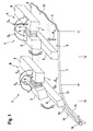
- FIG. 1 show a surface region 13 with a small curvature 14 and a surface region 12 with a strong curvature 15 toward an A pillar 16.
- the wiper device is shown here in two positions A and B, wherein the first position A is arranged in the region 13 of the low-curvature panorama plate 3 and the position B shows an example of the behavior of the wiper device according to the invention in the region 12 with a high curvature 15.
- the wiper device 1 has a wiper arm 4, which interacts with a pivot joint.
- the free pivotable end 7 is shown in Figure 1, on which in this embodiment of the invention, a wiper blade receptacle 2 is not arranged directly with a second pivot joint. Rather, an elastic element 5, which here has a bellows 6, laterally on the pivotable end 7 of the Wiper arm 4 arranged such.
- a torque occurs in the direction of arrow D A , which presses the attached to the spring element 5 wiper blade receptacle 2 with a wiper blade 8 in the direction of the surface 9 of the panoramic plate 3.
- the torque which is exerted by the bias of the wiper arm 4 in the direction of arrow D A is dimensioned so that the pre-curved elastic element 5 is arranged almost parallel to the surface 9 of the panoramic plate in this slightly curved surface region 13. This creates a contact pressure on the surface 9 of the panoramic plate 3, which acts against the panoramic plate 3 in the direction of arrow E A.
- the wiper device 1 reacts as shown in position B.
- the spring element 5 causes a torque D B , so that the wiper blade 8 is pressed with the wiper blade receptacle 2 on the strongly curved surface portion 12 in the vicinity of the A-pillar 16 of the vehicle.
- the spring element 5 is pre-curved and has a radius of curvature which is significantly smaller than the radius of curvature of the maximum curvature 15 of the panoramic plate 3. This leaves despite the shown with the direction of the arrow C B reduced contact force of the pivotable end 7 on the panoramic plate 3 in this Area, a sufficient contact pressure on the strongly curved surface portion 12 of the panoramic plate 3 obtained, so that a thorough cleaning is still guaranteed.
- the bellows 6 shown in Figure 1 may consist of a pre-curved spring-elastic material and thus form the elastic element. However, the bellows 6 can also form only a protective cover for an elastic element 5, which is arranged within the Federbalgs.
- the conventionally arranged on the pivotable end 7 of the wiper arm 4 second tilt joint for the wiper blade 8 is integrated in this embodiment of the invention in the wiper blade receptacle 2 and thus laterally offset from the pivotable wiper arm 7.
- it may also be integrated into the pivotable wiper arm end 7 as before.
- the elastic element 5 is arranged between the wiper blade and the pivotable wiper arm end 7.
- the pre-curved and elastic element 5 ensures that even in a strongly curved area, as shown in position B, that the wiper blade 8 is constantly applied to the panoramic window.
Landscapes
- Engineering & Computer Science (AREA)
- Mechanical Engineering (AREA)
- Pivots And Pivotal Connections (AREA)
- Transmission Devices (AREA)
- Vehicle Cleaning, Maintenance, Repair, Refitting, And Outriggers (AREA)
- Rear-View Mirror Devices That Are Mounted On The Exterior Of The Vehicle (AREA)
Abstract
Description
Die Erfindung betrifft eine Wischervorrichtung für eine Panoramascheibe eines Fahrzeugs und ein Verfahren zur Reinigung der Panoramascheibe. Dazu weist die Wischervorrichtung einen Wischerarm auf. Der Wischerarm ist mit einem fixierten Ende an einer Abtriebswelle eines Schwenkgetriebes über ein erstes Kippgelenk fixiert. An einem schwenkbaren Ende weist der Wischerarm ein Wischerblatt auf, das über eine Wischerblattaufnahme mit einem zweiten Kippgelenk an dem schwenkbaren Ende des Wischerarms angeordnet ist.The invention relates to a wiper device for a panoramic window of a vehicle and to a method for cleaning the panoramic window. For this purpose, the wiper device has a wiper arm. The wiper arm is fixed with a fixed end to an output shaft of a pivoting gear via a first tilting joint. At a pivotable end, the wiper arm has a wiper blade, which is arranged via a wiper blade receptacle with a second tilting joint on the pivotable end of the wiper arm.
Bei Panoramascheiben handelt es sich um Windschutzscheiben von Fahrzeugen, die ein verbreitertes Sichtfeld aufweisen, das durch ein nach hinten Ziehen der A-Säulen der Windschutzscheibe erreicht wird. Damit ist ein erweitertes Sichtfeld für den Fahrer in horizontaler Richtung verbunden. Diese konstruktive Maßnahme bringt jedoch eine starke Krümmung der Scheibe mit sich, die dabei teilweise Werte des Krümmungsradius von unter 1200 mm erreicht. Im Extremfall können Krümmungsradien von nur noch 700 mm im Bereich zu der A-Säule auftreten. Optimale Wischergebnisse mit gängigen Wischeranlagen können bisher nur bei Krümmungsradien von 2000 mm bis 8000 mm erzielt werden. Die besondere Schwierigkeit ergibt sich daraus, dass keine homogene Krümmung über den gesamten Verlauf der Panoramascheibe vorliegt, sondern vor allem zu den Seiten der ursprünglichen Positionen der A-Säulen hin die oben erwähnten besonders hohen Krümmungswerte auftreten.Panoramic windows are windshields of vehicles that have a broadened field of view that is achieved by pulling the A-pillars of the windshield backwards. This is an extended field of view for the driver connected in a horizontal direction. However, this constructive measure entails a strong curvature of the disc, which partially reaches values of the radius of curvature of less than 1200 mm. In extreme cases, radii of curvature of only 700 mm can occur in the area to the A-pillar. Optimal wiping results with common wiper systems can only be achieved with radii of curvature from 2000 mm to 8000 mm. The particular difficulty arises from the fact that there is no homogeneous curvature over the entire course of the panoramic window, but above all to the sides of the original positions of the A-pillars, the above-mentioned particularly high curvature values occur.
Aus der starken Krümmung zu den heutigen A-Säulen hin ergibt sich die erhöhte Schwierigkeit für die Kinematik der Wischervorrichtungen, die zu einer Abnahme der Wischqualität führen kann. Während der Wischbewegung kommt das freie obere Ende des Wischers in einem Bereich mit nur einem relativ flachen Winkel zum Anliegen, bzw. überstreicht diesen Bereich in einer weitgehend gestreckten Stellung. Je flacher dieser Winkel ist, umso mehr müsste das Wischerblatt verformt werden, um an die Krümmung der Windschutzscheibe quer zur Längsrichtung des Fahrzeugs angepasst zu werden. Ein gleichmäßiger Anpressdruck kann folglich nur schwer erreicht werden. Die Wischqualität nimmt infolge dessen ab. Hinzu kommt die Gefahr des Aufliegens der Federschiene an einem zu flachen Winkel zur Scheibe, was zu einem Rattern und im schlimmsten Fall zu einem Verkratzen der Panoramascheibe führen kann. Weitere Folgen sind Geräuschzunahme an der Umkehrposition des Wischers und eine Schleierbildung infolge des nicht exakten Aufliegens der Wischlippe des Wischers auf der Panoramascheibe.From the strong curvature to today's A-pillars, there is the increased difficulty for the kinematics of the wiper devices, which can lead to a decrease in wiping quality. During the wiping movement, the free upper end of the wiper comes to rest in an area with only a relatively shallow angle, or covers this area in a largely extended position. The shallower this angle is, the more the wiper blade would have to be deformed in order to be adapted to the curvature of the windshield transversely to the longitudinal direction of the vehicle. A uniform contact pressure can therefore be difficult to achieve. The wiping quality decreases as a result. In addition, there is the risk of resting the spring rail at a too flat angle to the disc, which can lead to a chattering and in the worst case to scratch the panoramic window. Further consequences are an increase in noise at the reversing position of the wiper and fogging due to the non-exact resting of the wiper lip of the wiper on the panoramic window.
Herkömmliche Wischeranlagen werden in den Befestigungspunkten über ein Entkopplungselement, dem ersten Kippgelenk, mit der Fahrzeugkarosserie fest verschraubt. Das Wischergelenk ist in einem Schaft als zweites Kippgelenk kippend gelagert, welcher mit den Befestigungspunkten über das Entkopplungselement - dem ersten Kippgelenk - verbunden ist. Um den geforderten Wert des Anstellwinkels des Wischerblatts zur Windschutzscheibe zu erreichen, braucht man gerade bei stark gekrümmten Windschutzscheiben ein Wischergelenk, welches die Wischlippe jeder Wischwinkelposition der Scheibenkrümmung optimal anpasst.Conventional wiper systems are firmly bolted to the vehicle body in the attachment points via a decoupling element, the first tilting joint. The wiper joint is tiltably mounted in a shaft as a second tilting joint, which is connected to the attachment points via the decoupling element - the first tilting joint. In order to achieve the required value of the angle of attack of the wiper blade to the windshield, one needs a wiper joint, which optimally adapts the wiper lip of each wiping angle position of the disk curvature, especially in the case of strongly curved windshields.
Besonders die herkömmlichen Wischergelenke stellen infolge ihrer steifen Anbindung, die für eine genaue Einhaltung der Wischwinkel sorgen, ein Hindernis dar. Auch die damit verbundene starre Anbindung des Wischerblatts des Wischers zum Wischarm stellt ein Hindernis bezüglich der dynamischen Veränderung des Wischfelds im Bereich der A-Säule dar. Somit können die Anforderungen, die an die Reinigung von stark gekrümmten Panoramascheiben - gerade im Bereich hin zur A-Säule - gestellt werden, mit den bekannten Wischvorrichtungskonzepten nicht erfüllt werden.In particular, the conventional wiper joints pose an obstacle due to their rigid connection, which ensure accurate compliance with the wiping angle. The associated rigid connection of the wiper blade of the wiper to the wiper arm is an obstacle to the dynamic change of the wiping field in the A-pillar Thus, the requirements that are placed on the cleaning of highly curved panoramic windows - straight in the area towards the A-pillar - can not be met with the known Wischvorrichtungskonzepte.
Aus der Druckschrift
Aufgabe der Erfindung ist es, eine Wischervorrichtung und ein Verfahren zur Reinigung von Panoramascheiben zu schaffen, welche es ermöglicht, die Bereiche einer Panoramascheibe mit Scheibenkrümmung besser zu reinigen.The object of the invention is to provide a wiper device and a method for cleaning panoramic windows, which makes it possible to better clean the areas of a panorama window with disc curvature.
Gelöst wird diese Aufgabe mit dem Gegenstand der unabhängigen Ansprüche. Vorteilhafte Weiterbildungen der Erfindung ergeben sich aus den abhängigen Ansprüchen.This object is achieved with the subject of the independent claims. Advantageous developments of the invention will become apparent from the dependent claims.
Erfindungsgemäß wird eine Wischervorrichtung für eine Panoramascheibe eines Fahrzeugs und ein Verfahren zur Reinigung der Panoramascheibe geschaffen. Dazu weist die Wischervorrichtung einen Wischerarm auf. Der Wischerarm ist mit einem fixierten Ende an einer Abtriebswelle eines Schwenkgetriebes über ein Kippgelenk fixiert. An einem schwenkbaren Ende weist der Wischerarm ein Wischerblatt auf, das über eine Wischerblattaufnahme mit Kippgelenk an dem schwenkbaren Ende des Wischerarms angeordnet ist. Das Wischerblatt ist seitlich versetzt zum schwenkbaren Ende des Wischerarms angeordnet. Zwischen dem schwenkbaren Ende des Wischerarms und dem Wischerblatt weist die Wischervorrichtung ein elastisches Element auf.According to the invention, a wiper device for a panoramic window of a vehicle and a method for cleaning the panoramic window are provided. For this purpose, the wiper device has a wiper arm. The wiper arm is fixed with a fixed end to an output shaft of a pivoting gear via a tilting joint. At a pivotable end, the wiper arm on a wiper blade, which is arranged via a wiper blade receptacle with tilting joint on the pivotable end of the wiper arm. The wiper blade is arranged laterally offset from the pivotable end of the wiper arm. Between the pivotable end of the wiper arm and the wiper blade, the wiper device has an elastic element.
Die erfindungsgemäße Wischervorrichtung hat aufgrund des elastischen Elements, das nicht nur wie bisher eine Kippbewegung um eine zweite Kippachse zulässt, sondern zusätzlich die Möglichkeit bietet, einer extremen Krümmung einer Panoramascheibe mit dem Wischerblatt zu folgen, den Vorteil, dass lediglich das Wischerblatt versetzt zu dem schwenkbaren Ende des Wischerarms anzuordnen ist, um die Elastizität des elastischen Elements für ein Anpassen des Wischerblattes an eine gekrümmte Oberfläche einer Panoramascheibe zu nutzen. Gleichzeitig wird damit die steife Anbindung des Wischerblattes an das schwenkbare Ende des Wischerarms durch die bisher übliche zweite Kippmöglichkeit des Wischers gegenüber der Windschutzscheibe aufgehoben.The wiper device according to the invention has the advantage that only the wiper blade offset from the pivotable due to the elastic element, which not only allows a tilting movement about a second tilting axis as before, but also offers the possibility to follow an extreme curvature of a panoramic disc with the wiper blade End of the wiper arm is to be used to use the elasticity of the elastic element for adapting the wiper blade to a curved surface of a panoramic window. simultaneously Thus, the rigid connection of the wiper blade to the pivotal end of the wiper arm is repealed by the previously common second possibility of tilting the wiper against the windshield.
Dabei kann das elastische Element am Wischerarm, an der Wischerblattaufnahme oder am Wischerblatt selbst seitlich versetzt angeordnet sein. Mit dieser seitlichen Versetzung zwischen Wischerblatt und Wischerarm wird durch die Veränderung des Hubwinkels und der damit verbundenen Veränderung der Auflagekraft mehr oder weniger Biegemoment auf das Wischerblatt übertragen und damit eine Änderung des Anstellwinkels zur Scheibennormalen erzeugt.In this case, the elastic element may be arranged laterally offset on the wiper arm, on the wiper blade receptacle or on the wiper blade itself. With this lateral displacement between the wiper blade and the wiper arm, more or less bending moment is transmitted to the wiper blade by the change in the lifting angle and the associated change in the bearing force, thus producing a change in the angle of attack for the disc normal.
Gesteuert wird diese Bewegung des seitlich zum Wischerarm versetzten Wischerblattes durch die variierende Anpresskraft, hervorgerufen durch den vom Wischerwinkel abhängigen Hubwinkelverlauf, wobei die variierende Anpresskraft durch den ausführungsbedingten Hebelarm ein Moment auf die Aufnahme ausübt. Durch die elastische Verformung des elastischen Elements findet eine aktive Steuerung des Anstellwinkels des Wischerblattes statt. Über zusätzliche Stützelemente am Wischerblatt kann ein Kippen über den optimalen Bereich des Anstellwinkels von plus fünf Grad bis minus vier Grad hinaus verhindert werden. Durch Einschränken der Bewegungs- und Kippfreiheit quer zur Wischerarmlängsrichtung wird ein Anschlagen des Wischerrückens auf der Scheibe verhindert.This movement of the wiper blade offset laterally relative to the wiper arm is controlled by the varying contact force caused by the stroke angle progression dependent on the wiper angle, wherein the varying contact force exerts a moment on the receptacle by the lever arm due to the execution. Due to the elastic deformation of the elastic element takes place an active control of the angle of attack of the wiper blade. Additional support elements on the wiper blade can prevent it from tilting beyond the optimum range of the angle of attack, from plus five degrees to minus four degrees. By limiting the freedom from movement and tilting transversely to the wiper arm longitudinal direction a striking of the wiper back is prevented on the disc.
Durch das elastische Element kann der für das Wischerblatt bzw. die Wischerlippe geforderte optimale Anstellwinkel zur Panoramascheibe in vorteilhafter Weise realisiert werden. Dazu ist es nicht erforderlich, das Standarddesign eines Wischerhebels bzw. eines Wischerarms in Zusammenwirkung mit einem Wischerblatt herkömmlicher Art grundlegend zu verändern. Auch ein zusätzlicher Bauraumbedarf für die Kinematik der erfindungsgemäßen Wischervorrichtung ist nicht notwendig. Schließlich folgt die Anstellwinkelsteuerung automatisch über gegebene Verhältnisse und es sind keine zusätzlichen Hilfsmittel zur Steuerung des Wischerblattes notwendig. Bis auf das elastische Element, das hier zur seitlichen Versetzung des Wischerblattes gegenüber dem Wischerarm eingefügt wird, sind keine zusätzlichen Verschleißteile erforderlich. Darüber hinaus ist die erfindungsgemäße Wischervorrichtung nahezu kostenneutral und völlig geräuscharm.By means of the elastic element, the optimum angle of attack required for the wiper blade or the wiper lip for the panoramic window can be realized in an advantageous manner. For this purpose, it is not necessary, the standard design of a wiper lever or a wiper arm in conjunction with a Wiper blade conventional type fundamentally change. An additional space requirement for the kinematics of the wiper device according to the invention is not necessary. Finally, the pitch control automatically follows given conditions and no additional tools are necessary to control the wiper blade. Except for the elastic element, which is inserted here for lateral displacement of the wiper blade relative to the wiper arm, no additional wearing parts are required. In addition, the wiper device according to the invention is almost cost-neutral and completely silent.
In einer bevorzugten Ausführungsform der Erfindung weist das elastische Element einen Faltenbalg auf. Ein derartiger Faltenbalg kann selber als elastisches Element vorbereitet werden, wenn dem Faltenbalg im entlasteten Zustand eine Krümmung aufgeprägt wird, wobei diese Krümmung des elastischen Elements größer als die maximale auftretende Krümmung der Panoramascheibe ist. Dabei unterscheidet sich eine starke Krümmung von einer geringen oder schwachen Krümmung dadurch, dass der Krümmungsradius eine starken Krümmung geringer ist als der Krümmungsradius einer schwachen oder geringen Krümmung. Außerdem kann ein Faltenbalg auch nur als Schutz vorgesehen werden, der selbst keine elastischen Eigenschaften aufweist und lediglich ein elastisches Element vor Beschädigungen schützt.In a preferred embodiment of the invention, the elastic element has a bellows. Such a bellows can be prepared itself as an elastic element when the bellows in the unloaded state, a curvature is impressed, said curvature of the elastic element is greater than the maximum occurring curvature of the panoramic window. In this case, a strong curvature differs from a slight or weak curvature in that the curvature radius is a strong curvature less than the curvature radius of a weak or small curvature. In addition, a bellows can also be provided only as protection, which itself has no elastic properties and only protects an elastic element from damage.
Der Vorteil eines elastischen Elements, das im elastischen Zustand eine Krümmung aufweist, die größer ist als die maximale auftretende Krümmung der Panoramascheibe, liegt darin, dass das Wischerblatt selbst bei der maximal auftretenden Krümmung der Panoramascheibe noch von dem elastischen Element auf die Oberfläche der Panoramascheibe gepresst wird und sich ein Anstellwinkel einstellt, der selbst im maximal gekrümmten Oberflächenbereich nahezu der Normalen zu der Oberfläche der Panoramascheibe entspricht. Dazu ist das elastische Element im belasteten Zustand in Richtung auf die Oberfläche der Panoramascheibe vorgespannt. Diese Vorspannung wird durch entsprechende Vorspannungselemente am Wischerarm wie bei konventionellen Wischeranlagen sichergestellt.The advantage of an elastic element, which has a curvature in the elastic state, which is greater than the maximum occurring curvature of the panoramic plate, is that the wiper blade pressed even at the maximum occurring curvature of the panoramic plate from the elastic element on the surface of the panoramic disc will and become sets an angle of attack, which corresponds to almost the normal to the surface of the panoramic window even in the maximum curved surface area. For this purpose, the elastic element is biased in the loaded state in the direction of the surface of the panoramic window. This bias is ensured by appropriate biasing elements on the wiper arm as in conventional wiper systems.
In einer weiteren Ausführungsform der Erfindung ist das elastische Element zwischen dem Wischerblatt und der Wischerblattaufnahme angeordnet, wobei die Wischerblattaufnahme mit dem zweiten Kippgelenk am schwenkbaren Ende des Wischerarms fixiert ist. Bei dieser Ausführungsform der Erfindung wird lediglich das Wischerblatt einer konventionellen Wischervorrichtung ausgewechselt und durch ein Wischerblatt ersetzt, welches das elastische und vorgekrümmte Element aufweist. Mit diesem elastische Element wird das Wischerblatt an dem schwenkbaren Ende des Wischerarms über eine dort befindliche Wischerblattaufnahme mit einem zweiten Kippelement angebracht.In a further embodiment of the invention, the elastic element between the wiper blade and the wiper blade receptacle is arranged, wherein the wiper blade receptacle is fixed to the second tilting joint on the pivotable end of the wiper arm. In this embodiment of the invention, only the wiper blade of a conventional wiper device is replaced and replaced by a wiper blade having the elastic and pre-curved member. With this elastic element, the wiper blade is attached to the pivotable end of the wiper arm via a wiper blade receptacle located there with a second tilting element.
Alternativ kann das elastische Element auch zwischen der Wischerblattaufnahme und dem schwenkbaren Ende des Wischerarms angeordnet sein, wobei die Wischerblattaufnahme mit zweitem Kippgelenk seitlich versetzt zum Wischerarmende angeordnet ist. In diesem Fall wird der Wischerarm mit der starren Zuordnung des zweiten Kippgelenks am Wischerarmende gegen einen Wischerarm ausgetauscht, der an seinem Wischerarmende das elastische und vorgekrümmte Element aufweist, an dem seitlich versetzt die Wischerblattaufnahme herkömmlicher Art mit zweitem Kippgelenk fixiert ist. Mit dieser Variante ist der Vorteil verbunden, dass herkömmliche Wischerblätter unverändert in der Wischerblattaufnahme angeordnet werden können.Alternatively, the elastic element can also be arranged between the wiper blade receptacle and the pivotable end of the wiper arm, wherein the wiper blade receptacle with the second tilting joint is arranged laterally offset from the wiper arm end. In this case, the wiper arm is exchanged with the rigid assignment of the second tilting joint at the wiper arm end against a wiper arm having at its Wischerarmende the elastic and pre-curved element on the side offset the wiper blade receptacle of conventional type is fixed with second tilt joint. This variant has the advantage that conventional wiper blades can be arranged unchanged in the wiper blade receptacle.
In einer bevorzugten Weiterbildung der Erfindung weist das elastische Element ein Federelement auf. Dieses Federelement kann eine vorgekrümmte Blattfeder oder eine vorgekrümmte Schraubenfeder sein. Ferner ist es möglich, als elastisches Element ein gummielastisches Element einzusetzen. Auch gummielastische Elemente können vorgekrümmt sein und dadurch einen entsprechenden Druck auf das Wischerblatt noch in einem Oberflächenbereich mit starker Krümmung auf die Panoramascheibe ausüben. Ferner ist es möglich, das elastische Element aus einem Metallgummielement herzustellen, wobei der gekrümmte Bereich gummielastisch ist und die Fixierungsenden des Metallgummielements, die einerseits mit dem Wischerarm und andererseits mit der Wischerblattaufnahme zu verbinden sind, aus metallischen Verbindungselementen bestehen.In a preferred development of the invention, the elastic element has a spring element. This spring element may be a pre-curved leaf spring or a pre-curved coil spring. Furthermore, it is possible to use a rubber-elastic element as the elastic element. Also rubber-elastic elements may be pre-curved and thereby exert a corresponding pressure on the wiper blade still in a surface area with a strong curvature on the panoramic window. Further, it is possible to manufacture the elastic member from a metal rubber member, wherein the curved portion is rubber-elastic and the fixing ends of the metal rubber member, which are to be connected on the one hand with the wiper arm and on the other hand with the wiper blade receptacle, consist of metallic connecting elements.
Ein Verfahren zur Reinigung einer Panoramascheibe eines Fahrzeugs weist unter Anwendung der obigen Wischervorrichtung folgende Verfahrensschritte auf. Zunächst wird ein Wischerarm zwischen einer Ruheposition und einer Umkehrposition unter Vorspannung hin- und hergeschwenkt. An dem schwenkbaren Ende ist dazu gelenkig und über ein elastisches, vorgekrümmtes Element seitlich versetzt ein Wischerblatt angebracht, wobei die Umkehrposition in einem stark gekrümmten Bereich einer Panoramascheibe und die Ruheposition in einem geringer gekrümmten Bereich der Panoramascheibe angeordnet werden. Beim Schwenken des Wischerarms erfolgt ein elastisches Verformen des elastischen und gekrümmten Elements unter der Vorspannung des Wischerarms auf Oberflächenbereichen der Panoramascheibe, die eine geringe Krümmung aufweisen, und es erfolgt ein elastisches Entspannen des elastischen und gekrümmten Elements unter Anpassung des Wischerblattes an die Krümmung der Panoramascheibe auf Oberflächenbereichen der Panoramascheibe, die eine starke Krümmung aufweisen. Mit diesem Verfahren wird in vorteilhafter Weise gewährleistet, dass eine Panoramascheibe in allen Krümmungsbereichen ihrer Oberfläche gleichmäßig gereinigt wird.A method for cleaning a panoramic window of a vehicle has the following method steps using the above wiper device. First, a wiper arm is pivoted back and forth between a rest position and a reverse position under bias. At the pivotable end, a wiper blade is articulated thereto and laterally offset via an elastic, precurved element, wherein the reversing position is arranged in a strongly curved region of a panorama window and the rest position in a slightly curved region of the panorama window. When pivoting the wiper arm is an elastic deformation of the elastic and curved element under the bias of the wiper arm on surface areas of the panoramic plate having a low curvature, and there is an elastic relaxation of the elastic and curved element while adapting the wiper blade to the curvature of the panoramic window Surface areas of the panoramic window, the have a strong curvature. With this method, it is advantageously ensured that a panoramic window is uniformly cleaned in all curved areas of its surface.
Die Erfindung wird nun anhand der beigefügten Figur näher erläutert.The invention will now be explained in more detail with reference to the accompanying figure.
- Figur 1FIG. 1
- zeigt eine Prinzipskizze einer Panoramascheibe mit einer Wischervorrichtung gemäß einer Ausführungsform der Erfindung.shows a schematic diagram of a panoramic window with a wiper device according to an embodiment of the invention.
Von der Panoramascheibe 3 sind in Figur 1 lediglich Ausschnitte gezeigt, die einen Oberflächenbereich 13 mit geringer Krümmung 14 zeigen und einen Oberflächenbereich 12 mit einer starken Krümmung 15 zu einer A-Säule 16 hin.Of the
Die Wischervorrichtung ist hier in zwei Positionen A und B gezeigt, wobei die erste Position A im Bereich 13 der Panoramascheibe 3 mit geringer Krümmung 14 angeordnet ist und die Position B ein Beispiel für das Verhalten der erfindungsgemäßen Wischervorrichtung im Bereich 12 mit starker Krümmung 15 zeigt.The wiper device is shown here in two positions A and B, wherein the first position A is arranged in the
Die Wischervorrichtung 1 weist einen Wischerarm 4 auf, der mit einem Schwenkgelenk zusammenwirkt. Von dem Wischerarm 4 ist in Figur 1 das freie schwenkbare Ende 7 gezeigt, an dem in dieser Ausführungsform der Erfindung eine Wischerblattaufnahme 2 mit einem zweiten Kippgelenk nicht direkt angeordnet ist. Vielmehr ist ein elastisches Element 5, das hier einen Faltenbalg 6 aufweist, seitlich am schwenkbaren Ende 7 des Wischerarms 4 derart angeordnet. Beim Anpressen des schwenkbaren Endes 7 in Pfeilrichtung CA in der Position A tritt ein Drehmoment in Pfeilrichtung DA auf, das die an dem Federelement 5 angebrachte Wischerblattaufnahme 2 mit einem Wischerblatt 8 in Richtung auf die Oberfläche 9 der Panoramascheibe 3 presst.The wiper device 1 has a
Das Drehmoment, das durch die Vorspannung des Wischerarms 4 in Pfeilrichtung DA ausgeübt wird, ist so bemessen, dass das vorgekrümmte elastische Element 5 nahezu parallel zur Oberfläche 9 der Panoramascheibe in diesem gering gekrümmten Oberflächenbereich 13 angeordnet ist. Dadurch entsteht ein Auflagedruck auf die Oberfläche 9 der Panoramascheibe 3, welchem die Panoramascheibe 3 in Pfeilrichtung EA entgegen wirkt.The torque which is exerted by the bias of the
Sobald der Wischerarm 4 in den Bereich mit starker Krümmung 15 weiterschwenkt, reagiert die erfindungsgemäße Wischervorrichtung 1 wie es Position B zeigt. Das Federelement 5 bewirkt ein Drehmoment DB, so dass das Wischerblatt 8 mit der Wischerblattaufnahme 2 auf den stark gekrümmten Oberflächenbereich 12 in der Nähe der A-Säule 16 des Fahrzeugs gepresst wird. Dazu ist das Federelement 5 vorgekrümmt und weist einen Krümmungsradius auf, der deutlich kleiner ist als der Krümmungsradius der maximalen Krümmung 15 der Panoramascheibe 3. Damit verbleibt, trotz der mit der Pfeilrichtung CB gezeigten verminderten Anpresskraft des schwenkbaren Endes 7 auf die Panoramascheibe 3 in diesem Bereich, ein genügender Anpressdruck auf den stark gekrümmten Oberflächenbereich 12 der Panoramascheibe 3 erhalten, so dass eine gründliche Reinigung weiterhin gewährleistet ist.As soon as the
Der in Figur 1 gezeigt Faltenbalg 6 kann aus einem vorgekrümmten federelastischen Material bestehen und somit das elastische Element bilden. Der Federbalg 6 kann jedoch auch lediglich eine Schutzhülle für ein elastisches Element 5 bilden, das innerhalb der Federbalgs angeordnet ist.The
Das konventionell am schwenkbaren Ende 7 des Wischerarms 4 angeordnete zweite Kippgelenk für das Wischerblatt 8 ist bei dieser Ausführungsform der Erfindung in der Wischerblattaufnahme 2 integriert und somit seitlich versetz zu dem schwenkbaren Wischerarmende 7 angeordnet. Es kann jedoch auch wie bisher in dem schwenkbaren Wischerarmende 7 integriert sein. In einem solchen Fall ist das elastische Element 5 zwischen Wischerblatt und schwenkbarem Wischerarmende 7 angeordnet.The conventionally arranged on the pivotable end 7 of the
Das vorgekrümmte und elastische Element 5 sorgt selbst in einem stark gekrümmten Bereich, wie er in Position B gezeigt wird, dafür dass das Wischerblatt 8 an der Panoramascheibe ständig anliegt.The pre-curved and
Claims (10)
dadurch gekennzeichnet, dass
das elastische Element (5) in einem Faltenbalg (6) angeordnet ist.Wiper device according to claim 1,
characterized in that
the elastic element (5) is arranged in a bellows (6).
dadurch gekennzeichnet, dass
das elastische Element (5) im entlasteten Zustand eine Krümmung aufweist, wobei die Krümmung des elastische Elements (5) größer als die maximale auftretende Krümmung der Panoramascheibe (3) ist.Wiper device according to claim 1 or claim 2,
characterized in that
the elastic element (5) has a curvature in the unloaded state, wherein the curvature of the elastic element (5) is greater than the maximum occurring curvature of the panoramic plate (3).
dadurch gekennzeichnet, dass
das elastische Element (5) im belasteten Zustand in Richtung auf die Oberfläche (9) der Panoramascheibe (3) vorgespannt ist.Wiper device according to claim 3,
characterized in that
the elastic element (5) is biased in the loaded state in the direction of the surface (9) of the panoramic plate (3).
dadurch gekennzeichnet, dass
das elastische Element (5) zwischen dem Wischerblatt (8) und der Wischerblattaufnahme (2) angeordnet ist, wobei die Wischerblattaufnahme (2) mit dem zweiten Kippgelenk am schwenkbaren Ende (7) des Wischerarms (4) fixiert ist.Wiper device according to claim 3,
characterized in that
the elastic element (5) is arranged between the wiper blade (8) and the wiper blade receptacle (2), wherein the wiper blade receptacle (2) with the second tilt joint is fixed on the pivotable end (7) of the wiper arm (4).
dadurch gekennzeichnet, dass
das elastische Element (5) zwischen der Wischerblattaufnahme (2) und dem schwenkbaren Ende (7) des Wischerarms (4) angeordnet ist, wobei die Wischerblattaufnahme (2) mit zweitem Kippgelenk seitlich versetzt zum Wischerarm (4) angeordnet ist.Wiper device according to one of claims 1 to 4,
characterized in that
the elastic element (5) is arranged between the wiper blade receptacle (2) and the pivotable end (7) of the wiper arm (4), wherein the wiper blade receptacle (2) with the second tilt joint is arranged offset laterally relative to the wiper arm (4).
dadurch gekennzeichnet, dass
das elastische Element (5) ein Federelement aufweist.Wiper device according to one of claims 1 to 6,
characterized in that
the elastic element (5) has a spring element.
dadurch gekennzeichnet, dass
das elastische Element (5) ein gummielastisches Element aufweist.Wiper device according to one of claims 1 to 6,
characterized in that
the elastic element (5) has a rubber-elastic element.
dadurch gekennzeichnet, dass
das elastische Element (5) ein Metallgummielement aufweist.Wiper device according to one of claims 1 to 6,
characterized in that
the elastic element (5) comprises a metal rubber element.
Applications Claiming Priority (2)
| Application Number | Priority Date | Filing Date | Title |
|---|---|---|---|
| DE102006046913 | 2006-10-04 | ||
| DE102007031560A DE102007031560A1 (en) | 2006-10-04 | 2007-07-06 | Wiper device for a panorama window and method for cleaning the panoramic window |
Publications (3)
| Publication Number | Publication Date |
|---|---|
| EP1908655A2 true EP1908655A2 (en) | 2008-04-09 |
| EP1908655A3 EP1908655A3 (en) | 2010-03-17 |
| EP1908655B1 EP1908655B1 (en) | 2015-09-02 |
Family
ID=38752473
Family Applications (1)
| Application Number | Title | Priority Date | Filing Date |
|---|---|---|---|
| EP07115800.0A Not-in-force EP1908655B1 (en) | 2006-10-04 | 2007-09-06 | Wiper device for a panoramic windscreen |
Country Status (3)
| Country | Link |
|---|---|
| EP (1) | EP1908655B1 (en) |
| DE (1) | DE102007031560A1 (en) |
| ES (1) | ES2547382T3 (en) |
Families Citing this family (2)
| Publication number | Priority date | Publication date | Assignee | Title |
|---|---|---|---|---|
| KR102727997B1 (en) | 2019-10-18 | 2024-11-07 | 현대자동차주식회사 | Apparatus for Contamination Preventative of Windshield Glass |
| DE102024123884B3 (en) * | 2024-08-21 | 2025-10-02 | Audi Aktiengesellschaft | Method for wiping a windscreen by means of a windscreen wiper device, windscreen wiper device and means of transport comprising a windscreen wiper device |
Family Cites Families (6)
| Publication number | Priority date | Publication date | Assignee | Title |
|---|---|---|---|---|
| US2973542A (en) * | 1955-11-22 | 1961-03-07 | Trico Products Corp | Windshield cleaner |
| US3393421A (en) * | 1966-09-30 | 1968-07-23 | Anderson Co | Connection means for establishing connection between a windshield wiper arm unit and a blade unit |
| JPS63199160A (en) * | 1987-02-16 | 1988-08-17 | Nippon Denso Co Ltd | Bearing device |
| DE19709051A1 (en) * | 1997-03-06 | 1998-09-10 | Bayerische Motoren Werke Ag | Windscreen wiper with support frame fixed on wiper arm has wiper strip guided by support frame and having wiper lip |
| AU2002221529A1 (en) * | 2000-10-28 | 2002-05-06 | Robert Bosch G.M.B.H | Device for detachably connecting a wiper blade to a driven wiper arm |
| EP1707459A3 (en) * | 2005-03-31 | 2013-10-23 | Valeo Systèmes d'Essuyage | Windshield wiper |
-
2007
- 2007-07-06 DE DE102007031560A patent/DE102007031560A1/en not_active Ceased
- 2007-09-06 EP EP07115800.0A patent/EP1908655B1/en not_active Not-in-force
- 2007-09-06 ES ES07115800.0T patent/ES2547382T3/en active Active
Also Published As
| Publication number | Publication date |
|---|---|
| EP1908655A3 (en) | 2010-03-17 |
| EP1908655B1 (en) | 2015-09-02 |
| ES2547382T3 (en) | 2015-10-05 |
| DE102007031560A1 (en) | 2008-04-10 |
Similar Documents
| Publication | Publication Date | Title |
|---|---|---|
| EP2917076B1 (en) | Windscreen wiper device for a vehicle | |
| EP1363816B1 (en) | Wiper arm with a pivoting connected wiper blade | |
| EP1363817B1 (en) | Wiper device especially for the panes of motor vehicles | |
| EP1940660A1 (en) | Windscreen wiper arm | |
| DE19859077A1 (en) | windshield wipers | |
| DE102005052036A1 (en) | Wiper system for windshields in motor vehicles has wiper blade, bearing part whereby connecting position of bearing part and mounting element is arranged beside axis and bearing part swivels around axis | |
| DE10026819A1 (en) | Four-bar wiper lever | |
| EP1908655B1 (en) | Wiper device for a panoramic windscreen | |
| DE69503292T2 (en) | Two-blade wiper on one arm | |
| EP3172095A1 (en) | Quick fastening for fin ray wipers | |
| EP1908654B1 (en) | Windscreen wiper device | |
| EP1931544A1 (en) | Wiper arm assembly | |
| DE102013225249A1 (en) | Windscreen wiper device for a vehicle | |
| EP1701870B1 (en) | Wiper system for wiping a windscreen | |
| EP1908653B1 (en) | Wiper device for a panoramic windscreen and method for cleaning the panoramic windscreen | |
| WO2001028826A1 (en) | Windscreen wiper arrangement for vehicles | |
| DE102013226351B4 (en) | Wiper arm and wiper mechanism | |
| DE102004026552B4 (en) | Drive device for a wiper arm of a windshield wiper system | |
| DE19547540B4 (en) | Windscreen wipers with anti-rattle agents | |
| DE102006062003A1 (en) | Windscreen wiper device, in particular in a motor vehicle | |
| EP1303429A1 (en) | Device for driving a wiper arm | |
| WO2008040643A1 (en) | Wiper blade for cleaning a windscreen | |
| EP3172096B1 (en) | Safety coupling for fin ray wiper | |
| DE3923623A1 (en) | AIR DEFLECTING BLADE FOR WINDOW WIPER DEVICE | |
| DE102019201537A1 (en) | Coupling device |
Legal Events
| Date | Code | Title | Description |
|---|---|---|---|
| PUAI | Public reference made under article 153(3) epc to a published international application that has entered the european phase |
Free format text: ORIGINAL CODE: 0009012 |
|
| AK | Designated contracting states |
Kind code of ref document: A2 Designated state(s): AT BE BG CH CY CZ DE DK EE ES FI FR GB GR HU IE IS IT LI LT LU LV MC MT NL PL PT RO SE SI SK TR |
|
| AX | Request for extension of the european patent |
Extension state: AL BA HR MK RS |
|
| PUAL | Search report despatched |
Free format text: ORIGINAL CODE: 0009013 |
|
| AK | Designated contracting states |
Kind code of ref document: A3 Designated state(s): AT BE BG CH CY CZ DE DK EE ES FI FR GB GR HU IE IS IT LI LT LU LV MC MT NL PL PT RO SE SI SK TR |
|
| AX | Request for extension of the european patent |
Extension state: AL BA HR MK RS |
|
| 17P | Request for examination filed |
Effective date: 20100917 |
|
| 17Q | First examination report despatched |
Effective date: 20101012 |
|
| AKX | Designation fees paid |
Designated state(s): CZ DE ES FR |
|
| GRAP | Despatch of communication of intention to grant a patent |
Free format text: ORIGINAL CODE: EPIDOSNIGR1 |
|
| INTG | Intention to grant announced |
Effective date: 20150529 |
|
| GRAS | Grant fee paid |
Free format text: ORIGINAL CODE: EPIDOSNIGR3 |
|
| GRAA | (expected) grant |
Free format text: ORIGINAL CODE: 0009210 |
|
| AK | Designated contracting states |
Kind code of ref document: B1 Designated state(s): CZ DE ES FR |
|
| REG | Reference to a national code |
Ref country code: ES Ref legal event code: FG2A Ref document number: 2547382 Country of ref document: ES Kind code of ref document: T3 Effective date: 20151005 |
|
| REG | Reference to a national code |
Ref country code: DE Ref legal event code: R096 Ref document number: 502007014184 Country of ref document: DE |
|
| REG | Reference to a national code |
Ref country code: FR Ref legal event code: PLFP Year of fee payment: 9 |
|
| REG | Reference to a national code |
Ref country code: DE Ref legal event code: R097 Ref document number: 502007014184 Country of ref document: DE |
|
| PLBE | No opposition filed within time limit |
Free format text: ORIGINAL CODE: 0009261 |
|
| STAA | Information on the status of an ep patent application or granted ep patent |
Free format text: STATUS: NO OPPOSITION FILED WITHIN TIME LIMIT |
|
| 26N | No opposition filed |
Effective date: 20160603 |
|
| REG | Reference to a national code |
Ref country code: FR Ref legal event code: PLFP Year of fee payment: 10 |
|
| REG | Reference to a national code |
Ref country code: FR Ref legal event code: PLFP Year of fee payment: 11 |
|
| REG | Reference to a national code |
Ref country code: FR Ref legal event code: PLFP Year of fee payment: 12 |
|
| PGFP | Annual fee paid to national office [announced via postgrant information from national office to epo] |
Ref country code: FR Payment date: 20180921 Year of fee payment: 12 |
|
| PGFP | Annual fee paid to national office [announced via postgrant information from national office to epo] |
Ref country code: CZ Payment date: 20180903 Year of fee payment: 12 |
|
| PGFP | Annual fee paid to national office [announced via postgrant information from national office to epo] |
Ref country code: ES Payment date: 20181024 Year of fee payment: 12 |
|
| PG25 | Lapsed in a contracting state [announced via postgrant information from national office to epo] |
Ref country code: CZ Free format text: LAPSE BECAUSE OF NON-PAYMENT OF DUE FEES Effective date: 20190906 |
|
| PG25 | Lapsed in a contracting state [announced via postgrant information from national office to epo] |
Ref country code: FR Free format text: LAPSE BECAUSE OF NON-PAYMENT OF DUE FEES Effective date: 20190930 |
|
| REG | Reference to a national code |
Ref country code: ES Ref legal event code: FD2A Effective date: 20210127 |
|
| PGFP | Annual fee paid to national office [announced via postgrant information from national office to epo] |
Ref country code: DE Payment date: 20201121 Year of fee payment: 14 |
|
| PG25 | Lapsed in a contracting state [announced via postgrant information from national office to epo] |
Ref country code: ES Free format text: LAPSE BECAUSE OF NON-PAYMENT OF DUE FEES Effective date: 20190907 |
|
| REG | Reference to a national code |
Ref country code: DE Ref legal event code: R119 Ref document number: 502007014184 Country of ref document: DE |
|
| PG25 | Lapsed in a contracting state [announced via postgrant information from national office to epo] |
Ref country code: DE Free format text: LAPSE BECAUSE OF NON-PAYMENT OF DUE FEES Effective date: 20220401 |