EP3172096B1 - Safety coupling for fin ray wiper - Google Patents
Safety coupling for fin ray wiper Download PDFInfo
- Publication number
- EP3172096B1 EP3172096B1 EP15738302.7A EP15738302A EP3172096B1 EP 3172096 B1 EP3172096 B1 EP 3172096B1 EP 15738302 A EP15738302 A EP 15738302A EP 3172096 B1 EP3172096 B1 EP 3172096B1
- Authority
- EP
- European Patent Office
- Prior art keywords
- fastening
- wiper blade
- coupling
- wiper
- fastening part
- Prior art date
- Legal status (The legal status is an assumption and is not a legal conclusion. Google has not performed a legal analysis and makes no representation as to the accuracy of the status listed.)
- Active
Links
- 230000008878 coupling Effects 0.000 title claims description 95
- 238000010168 coupling process Methods 0.000 title claims description 95
- 238000005859 coupling reaction Methods 0.000 title claims description 95
- 229910052751 metal Inorganic materials 0.000 claims description 3
- 239000002184 metal Substances 0.000 claims description 2
- 239000000463 material Substances 0.000 description 8
- 238000000034 method Methods 0.000 description 8
- 230000008859 change Effects 0.000 description 5
- 238000001746 injection moulding Methods 0.000 description 5
- 230000006978 adaptation Effects 0.000 description 4
- 230000005540 biological transmission Effects 0.000 description 4
- 230000006835 compression Effects 0.000 description 4
- 238000007906 compression Methods 0.000 description 4
- 239000004033 plastic Substances 0.000 description 3
- 230000008901 benefit Effects 0.000 description 2
- 230000007423 decrease Effects 0.000 description 2
- 230000000694 effects Effects 0.000 description 2
- 238000004519 manufacturing process Methods 0.000 description 2
- 238000000926 separation method Methods 0.000 description 2
- 229920002725 thermoplastic elastomer Polymers 0.000 description 2
- 241000251468 Actinopterygii Species 0.000 description 1
- 238000005452 bending Methods 0.000 description 1
- 230000015572 biosynthetic process Effects 0.000 description 1
- 238000004140 cleaning Methods 0.000 description 1
- 230000001419 dependent effect Effects 0.000 description 1
- 238000010586 diagram Methods 0.000 description 1
- 238000006073 displacement reaction Methods 0.000 description 1
- 238000009826 distribution Methods 0.000 description 1
- 238000005755 formation reaction Methods 0.000 description 1
- 230000006872 improvement Effects 0.000 description 1
- 238000005304 joining Methods 0.000 description 1
- 230000007246 mechanism Effects 0.000 description 1
- 238000003825 pressing Methods 0.000 description 1
- 230000008569 process Effects 0.000 description 1
- 230000000750 progressive effect Effects 0.000 description 1
- 230000000284 resting effect Effects 0.000 description 1
- 239000000243 solution Substances 0.000 description 1
Images


Classifications
-
- B—PERFORMING OPERATIONS; TRANSPORTING
- B60—VEHICLES IN GENERAL
- B60S—SERVICING, CLEANING, REPAIRING, SUPPORTING, LIFTING, OR MANOEUVRING OF VEHICLES, NOT OTHERWISE PROVIDED FOR
- B60S1/00—Cleaning of vehicles
- B60S1/02—Cleaning windscreens, windows or optical devices
- B60S1/04—Wipers or the like, e.g. scrapers
- B60S1/32—Wipers or the like, e.g. scrapers characterised by constructional features of wiper blade arms or blades
- B60S1/38—Wiper blades
- B60S1/3801—Wiper blades characterised by a blade support harness consisting of several articulated elements
-
- B—PERFORMING OPERATIONS; TRANSPORTING
- B60—VEHICLES IN GENERAL
- B60S—SERVICING, CLEANING, REPAIRING, SUPPORTING, LIFTING, OR MANOEUVRING OF VEHICLES, NOT OTHERWISE PROVIDED FOR
- B60S1/00—Cleaning of vehicles
- B60S1/02—Cleaning windscreens, windows or optical devices
- B60S1/04—Wipers or the like, e.g. scrapers
- B60S1/32—Wipers or the like, e.g. scrapers characterised by constructional features of wiper blade arms or blades
- B60S1/34—Wiper arms; Mountings therefor
- B60S1/342—Wiper arms; Mountings therefor with means for temporarily uncoupling the wiper arm from the drive
-
- B—PERFORMING OPERATIONS; TRANSPORTING
- B60—VEHICLES IN GENERAL
- B60S—SERVICING, CLEANING, REPAIRING, SUPPORTING, LIFTING, OR MANOEUVRING OF VEHICLES, NOT OTHERWISE PROVIDED FOR
- B60S1/00—Cleaning of vehicles
- B60S1/02—Cleaning windscreens, windows or optical devices
- B60S1/04—Wipers or the like, e.g. scrapers
- B60S1/32—Wipers or the like, e.g. scrapers characterised by constructional features of wiper blade arms or blades
- B60S1/34—Wiper arms; Mountings therefor
- B60S1/3425—Constructional aspects of the arm
- B60S1/3445—Joints between elements
- B60S1/345—Joints between elements the elements being a link piece and a mounting head
- B60S1/3452—Joints between elements the elements being a link piece and a mounting head the joint being a snap fit pivot joint
-
- B—PERFORMING OPERATIONS; TRANSPORTING
- B60—VEHICLES IN GENERAL
- B60S—SERVICING, CLEANING, REPAIRING, SUPPORTING, LIFTING, OR MANOEUVRING OF VEHICLES, NOT OTHERWISE PROVIDED FOR
- B60S1/00—Cleaning of vehicles
- B60S1/02—Cleaning windscreens, windows or optical devices
- B60S1/04—Wipers or the like, e.g. scrapers
- B60S1/32—Wipers or the like, e.g. scrapers characterised by constructional features of wiper blade arms or blades
- B60S1/34—Wiper arms; Mountings therefor
- B60S1/3425—Constructional aspects of the arm
- B60S1/3445—Joints between elements
- B60S1/345—Joints between elements the elements being a link piece and a mounting head
- B60S1/3454—Joints between elements the elements being a link piece and a mounting head the joint being at end of mounting head furthest away from blade
-
- B—PERFORMING OPERATIONS; TRANSPORTING
- B60—VEHICLES IN GENERAL
- B60S—SERVICING, CLEANING, REPAIRING, SUPPORTING, LIFTING, OR MANOEUVRING OF VEHICLES, NOT OTHERWISE PROVIDED FOR
- B60S1/00—Cleaning of vehicles
- B60S1/02—Cleaning windscreens, windows or optical devices
- B60S1/04—Wipers or the like, e.g. scrapers
- B60S1/32—Wipers or the like, e.g. scrapers characterised by constructional features of wiper blade arms or blades
- B60S1/34—Wiper arms; Mountings therefor
- B60S1/3425—Constructional aspects of the arm
- B60S1/3445—Joints between elements
- B60S1/3459—Joints between elements the element being a mounting head and a shaft
-
- B—PERFORMING OPERATIONS; TRANSPORTING
- B60—VEHICLES IN GENERAL
- B60S—SERVICING, CLEANING, REPAIRING, SUPPORTING, LIFTING, OR MANOEUVRING OF VEHICLES, NOT OTHERWISE PROVIDED FOR
- B60S1/00—Cleaning of vehicles
- B60S1/02—Cleaning windscreens, windows or optical devices
- B60S1/04—Wipers or the like, e.g. scrapers
- B60S1/32—Wipers or the like, e.g. scrapers characterised by constructional features of wiper blade arms or blades
- B60S1/34—Wiper arms; Mountings therefor
- B60S1/3488—Means for mounting wiper arms onto the vehicle
- B60S1/3495—Means for mounting the drive mechanism to the wiper shaft
-
- B—PERFORMING OPERATIONS; TRANSPORTING
- B60—VEHICLES IN GENERAL
- B60S—SERVICING, CLEANING, REPAIRING, SUPPORTING, LIFTING, OR MANOEUVRING OF VEHICLES, NOT OTHERWISE PROVIDED FOR
- B60S1/00—Cleaning of vehicles
- B60S1/02—Cleaning windscreens, windows or optical devices
- B60S1/04—Wipers or the like, e.g. scrapers
- B60S1/32—Wipers or the like, e.g. scrapers characterised by constructional features of wiper blade arms or blades
- B60S1/40—Connections between blades and arms
-
- B—PERFORMING OPERATIONS; TRANSPORTING
- B60—VEHICLES IN GENERAL
- B60S—SERVICING, CLEANING, REPAIRING, SUPPORTING, LIFTING, OR MANOEUVRING OF VEHICLES, NOT OTHERWISE PROVIDED FOR
- B60S1/00—Cleaning of vehicles
- B60S1/02—Cleaning windscreens, windows or optical devices
- B60S1/04—Wipers or the like, e.g. scrapers
- B60S1/32—Wipers or the like, e.g. scrapers characterised by constructional features of wiper blade arms or blades
- B60S1/38—Wiper blades
- B60S2001/3812—Means of supporting or holding the squeegee or blade rubber
Definitions
- the invention relates to a windshield wiper device for a vehicle, in particular a motor vehicle.
- Windshield wiper devices typically have a wiper arm or wiper lever, with a wiper blade being moved on the window of a motor vehicle.
- the wiper blade is moved between a first turning position and a second turning position.
- the wiper arm is connected to a wiper motor via the drive shaft.
- the wiper blade easily loses contact with the windscreen, particularly on windshields with large changes in curvature and with large temperature fluctuations. This can lead to unwiped wiping areas or fog, especially in the case of strongly curved panes.
- a wiping process has to be optimized for a variety of parameters, such as the amount of rain on the windshield, a possible snow load on the windshield, the speed of the vehicle and the associated wind pressure on the wiper arm, it is not easy to create a fog by adjusting the pressure of the wiper arm on the windshield can be reliably prevented. Therefore, there is a need to further improve windshield wipers.
- a windshield wiper device for a vehicle is provided with a fastening element, in particular a motor vehicle, fastened to a drive shaft.
- the windshield wiper device includes a wiper blade with an elongated upper part which is at least partially bendable, an elongated lower part which is at least partially bendable, and a plurality of connecting elements for connecting the upper part and the lower part, the connecting elements being spaced apart from one another along a longitudinal extent of the wiper blade , and wherein the connecting elements are designed to allow movement of the upper part and the lower part relative to one another with a movement component along a longitudinal extension of the wiper blade.
- the windshield wiper device further includes a wiper blade-side fastening part, the wiper blade-side fastening part being releasably connectable to the fastening element, and a coupling device, the wiper blade-side fastening part and the fastening element being rotationally rigidly connectable by the coupling device until a defined torque value is exceeded.
- windshield wiper devices for vehicles with an overload safety device can be provided and assembled in a particularly advantageous manner and for a plurality of different areas of use. Furthermore, the embodiments of the invention enable a reliable, largely streak-free wiping of a window of a vehicle.
- a windshield wiper device for a vehicle is provided with a fastening element, in particular a motor vehicle, fastened to a drive shaft.
- the windshield wiper device includes a wiper blade with an elongated upper part which is at least partially bendable, an elongated lower part which is at least partially bendable, and a plurality of connecting elements for connecting the upper part and the lower part, the connecting elements being spaced apart from one another along a longitudinal extent of the wiper blade , and wherein the connecting elements are designed to allow movement of the upper part and the lower part relative to one another with a movement component along a longitudinal extension of the wiper blade.
- the windshield wiper device further includes a wiper blade-side fastening part, the wiper blade-side fastening part being releasably connectable to the fastening element, and a coupling device, the wiper blade-side fastening part and the fastening element being rotationally rigidly connectable by the coupling device until a defined torque value is exceeded.
- a fastening concept for a windshield wiper device can be made available, which is the drive shaft connects to the wiper arm in a rotationally fixed manner during normal operation and at the same time prevents damage to the wiper arm in the event of excessive loads on the wiper arm.
- the fastening element on the wiper blade side can be detached from the fastening element when the defined torque value is exceeded, the fastening element being released from the fastening element in particular when the defined torque value is exceeded. This ensures a reliable separation of the affected components and prevents damage to the components due to high speed loads.
- the windshield wiper device further includes the fastening element, the coupling device in particular comprising a coupling element which is attached to the fastening element and moves when the defined torque value is reached.
- the fastening part of the wiper arm for fastening to the fastening element can also have a cavity which provides contact surfaces for the fastening element. This allows the wiper arm to be installed simply and inexpensively while the function of the movable coupling element remains in the fastening element.
- the coupling device produces a force and / or positive connection between the fastening element and the fastening part of the wiper arm at torque values below the defined torque value.
- a rotationally rigid connection can be provided between the fastening element and the fastening part, and in particular the rotation of the drive shaft, to which the fastening element can be fastened, is transmitted to the wiper blade.
- the coupling device has a coupling element with a radius and a guide element which is at least partially applied to the coupling element at torques below the defined torque, in particular the coupling element on the fastening element is attached and the guide element is attached to the fastening part of the wiper arm.
- a rotationally rigid connection between the fastening element and the fastening part can be produced by the guide element resting on the coupling element. It is advantageous that both the stable support of the fastening part of the wiper blade on the fastening element and the coupling function of the coupling element and the guide element can be provided.
- the coupling device further comprises a force generating element, in particular a spring, which is attached to the coupling element.
- a force generating element on the coupling element, the coupling element can be held in a stable position up to a specific force or a specific moment which acts on the force generating element.
- the coupling element and the guide element are designed in such a way that the coupling element with a radius slips through the guide element when the defined torque is reached and in particular releases the rotationally rigid connection between the fastening element and the fastening part.
- the slipping of the coupling element can be caused in particular by the mutual design of the coupling element radius and the guide element.
- an appropriately designed force generating element can also determine the torque limit at which the coupling element slips through the guide element. This is an easy to implement and reliable way to implement the security concept of the embodiments described herein.
- the coupling device comprises a slip clutch.
- a slip clutch Through the use of a slip clutch, further safety-relevant aspects are included, in particular the following
- the wiper blade-side fastening part is formed in one piece, the wiper blade-side fastening part being in particular adapted to be made available in one step by means of an injection molding method, in particular an injection molding method.
- the wiper blade-side fastening part has a cavity, in which cavity there is a guide element of the coupling device, and the wiper blade-side fastening part in particular furthermore has a contact point. This represents a reliable rotationally rigid fastening of the fastening part and the fastening element.
- the fastening part on the wiper blade side can be designed to be metal-free and / or without movable elements. This can also serve a simple configuration.
- a wiper blade can be manufactured inexpensively as a spare part.
- the wiper blade-side fastening part can be designed to enable rotation relative to the fastening element about an axis perpendicular to the longitudinal extension of the wiper blade and perpendicular to the drive axis relative to the fastening element with a torque smaller than the defined torque.
- a defined contact pressure of a wiper lip against a pane can be made available.
- the rotation of the fastening part relative to the fastening element is restricted in an angular range of 30 ° or less. It is therefore not a matter of a rotation which corresponds to a folding down of the wiper blade from the window.
- the plurality of connection elements can be connected to the upper part and at a plurality of upper connection positions be connected to the lower part at a plurality of lower corresponding connection positions, the distance between an upper connection position and a corresponding lower connection position being substantially constant, in particular constant with a deviation of ⁇ 1 mm, when the upper part and the lower part move relative to one another.
- a power transmission between the upper part and the lower part can be made available, which enables a windshield wiper device that works according to the finray principle.
- a method for limiting a torque acting on a wiper arm of a windshield wiper device includes providing a fastener that is attachable to a drive shaft of a vehicle; and the provision of a wiper blade with fastening part, which is releasably connectable to the fastening element.
- the method further comprises assembling the fastening part of the wiper arm with the fastening element by means of a coupling device, in particular a coupling device with a coupling element and a guide element, whereby the joining produces a connection which is rotationally rigid up to a defined torque of the wiper blade between the fastening element and the fastening part of the wiper arm becomes.
- a safety concept for a windshield wiper device can thus be provided which prevents damage to the wiper blade under high torque loads.
- the method can further include pressing the coupling element against the guide element by a force generating element, in particular a spring. This ensures a secure fit during normal operation, i.e. guaranteed without the influence of high torque on the wiper arm.
- FIG. 1 shows a schematic representation of a section of a wiper blade 2, which can be part of a windshield wiper device for a vehicle, in particular for a motor vehicle, according to embodiments of the invention.
- Figure 1 shows the windshield wiper device in a position applied to a windshield 4.
- the wiper blade 2 comprises an elongated upper part 10 and an elongated lower part 12, which are designed to be at least partially bendable.
- a plurality of connecting elements 18 are provided for connecting the upper part 10 and the lower part 12, the connecting elements 18 being spaced apart from one another along a longitudinal extent 8 of the wiper blade 2.
- the connecting elements 18 are designed to allow the upper part 10 and the lower part 12 to move relative to one another with a movement component along a longitudinal extension of the wiper blade 2.
- the connecting elements are connected to the upper part 10 at a respective upper connecting position and to the lower part 12 at a respective lower connecting position.
- a swivel joint is provided at the connection positions.
- the distance from an upper connection position to a lower connection position on the same connection element essentially does not change, ie the distance is constant with deviations of, for example, ⁇ 1 mm, in particular ⁇ 0.3 mm.
- the wiper blade 2 has a head end 70.
- a fastening part 30, i.e. a wiper blade-side fastening part 30 is provided.
- the distance between the upper part 10 and the lower part 12 starting from the head end becomes smaller, at least in regions of the longitudinal extent of the wiper blade or in a predominant part of the longitudinal extent of the wiper blade.
- the height of the wiper blade tapers in areas or becomes smaller in areas of the longitudinal extent.
- the length of the connection elements can be provided for a plurality of the connection elements in such a way that the connection elements provided at the head end are longer than those on the opposite side of the wiper blade along the longitudinal extent.
- These properties make it possible to provide a windshield wiper device that works according to the finray principle.
- These windshield wiper devices typically have no joint in order to lift the wiper blade or a wiper lip off a window, for example a window of a motor vehicle.
- the wiper blade 2 is released from a fastening element 50 provided on a drive shaft 130 by means of a quick fix.
- Figure 1 shows a fastening part 30 on the wiper blade side and a fastening element 50.
- a translational movement takes place, which can be aligned essentially along the axis of the drive shaft 130, for example. If necessary, this movement can include an angle with the drive shaft of ⁇ 15 ° or less.
- a torsion or a rotation of the fastening part 30 about an axis parallel to the longitudinal extent of the wiper blade can be limited or excluded by guide elements in the fastening part 30 or a fastening element 50.
- Figure 2 shows a section of a wiper blade 2 of a windshield wiper device according to embodiments of the invention, a fastening part 30 being formed at the head end 70 of the wiper blade 2, that is to say a fastening part on the wiper blade side which can be detachably connected to a fastening element 50.
- the fastening element 50 is provided on a drive shaft 130.
- the fastener 50 is clamped to the drive shaft, for example, so that rotation of the drive shaft 130 is transmitted to the fastener 50. This rotation is in turn transmitted to the fastening part 30, so that the wiper blade 2 rotates on a window of a vehicle, for example a motor vehicle.
- the wiper blade 2 includes an upper part 12, a lower part 10 and a plurality of connecting elements 18.
- the fastening part 30 includes a cavity and an opening 210.
- the cavity is designed to receive the fastening element 50.
- the opening 210 is adapted so that a coupling element 21 of a coupling device can be inserted into the opening.
- the opening 210 can also be referred to as a guide element of a coupling device.
- opening 210 provides a support 230, the lower region being the region of opening 210 that faces a pane.
- An exemplary embodiment of a windshield wiper device comprises a coupling device which can connect the fastening element and the fastening part of the wiper arm to one another in a rotationally rigid manner up to a predefined torque, so that the rotation of the drive shaft 130 can be transmitted to the wiper arm when the windshield wiper is actuated in the vehicle.
- the coupling device allows a (functional or constructive) separation of the fastening element and the fastening part when the defined torque is exceeded.
- the connection of the fastening element and the fastening part is released in such a way that the wiper arm is released from the fastening element.
- a coupling device is provided in the windshield wiper device, which interrupts the connection transmitting the rotation of the drive shaft when the defined torque is exceeded, while the fastening element and the Fastening part remain attached to each other.
- a coupling device can comprise, for example, a slip clutch.
- a rotational position about an axis perpendicular to the longitudinal extension of the wiper blade and perpendicular to the axis of the drive shaft (or perpendicular to the linear mounting direction) is defined by a first contact point and a second contact point between the wiper blade-side fastening part 30 and in the fastening element 50.
- the position of the wiper blade 2 is thus defined without being overdetermined.
- the first contact point is provided by a guide element of the coupling device, which is provided between the axis of rotation of the drive shaft 130 and a connecting element 18, and the second contact point is provided by a stop, for example on the opposite side the drive shaft 130 is provided.
- the stop 232 which is provided on the fastening element 50 in order to define the rotational position with a corresponding position of the fastening part 30, can be provided on a movable element 254.
- Movable member 254 may be, for example, a pin movable in a guide.
- the movement of the movable member 254 can be defined by a spring 252 that applies a force to the stop 232. If, for example, a force is increased which acts on the lower part 10 when the wiper blade 2 is wiped, the stop 232 is moved downward via the lever, that is to say the spring 252 is loaded with a greater force. Movable member 254 moves down.
- the stop 232 has a variable position, with a lever around the support 230.
- a force acting on the underside of the wiper blade or a wiper lip attached to the underside can be from 2 Newtons to 10 Newtons, for example approximately 5 Newtons, via a lever ratio of a spring force of 8 Newtons up to 40 newtons, approximately 20 newtons.
- a fastening element 50 can also be designed without a spring.
- a fixed rotational position is made available by the stop 232.
- Movable element 254 becomes a fixed element.
- the position of the stop can be provided by different lengths of this fixed element or by different adapters or attachments on the fixed element. This predefined variation of the stop or the contact point can be used, for example, to set the use of a windshield wiper device on a specific vehicle type.
- the guide element which can provide a support during normal operation, for example, and a stop, i.e. a first contact point and a second contact point, provide a rotational position about an axis perpendicular to the longitudinal extension of the wiper blade and perpendicular to the axis of the drive shaft in Dependence of a force provided on the wiper blade.
- the wiper blade can rotate in normal operation about an axis perpendicular to the longitudinal extent of the wiper blade and perpendicular to the axis of the drive shaft.
- the coupling element 21 as in FIG Fig. 2 shown, a radius is available in a radius section, while it is essentially straight in the remaining part.
- the guide element 210 can partially surround the radius section during normal operation, ie if the defined torque has not yet been reached, and can find a contact point in the remaining part, which is essentially straight.
- the radius section of the coupling element is in the assembled state at an end of the wiper arm facing the connecting elements 18.
- the radius is arranged such that the curvature of the radius extends in the direction around the drive axis.
- the radius such as in the Figure 3 shown, pointing in the direction of the connecting elements of the wiper arm in the assembled state.
- normal operation is to be understood as a load case for the wiper arm in which the defined torque value is not exceeded.
- FIG. 3 shows an embodiment of the windshield wiper device according to the invention with a coupling device.
- Fig. 3 shows a sectional view along a sectional plane that runs substantially parallel to the top of the wiper blade.
- the windshield wiper device comprises a coupling element 210 with a radius at a radius section and a guide element 210.
- the coupling element 21 is fastened with a force generating element, in particular with a spring 211.
- the guide element 210 can hold the coupling element 21 in a defined position, in particular in a defined rotational position, during normal operation. If, according to arrow 222 in Fig.
- a torque acts on the wiper arm of the windshield wiper device, and this torque exceeds the defined torque value, the coupling element 21 can slip through the guide element, in particular through the design of the radius and the corresponding load from the guide element. As a result, the guide element can no longer provide a support function and the connection between the fastening element and the fastening part of the wiper arm is released.
- the spring 211 can co-determine the setting of the defined torque value and allow a deflection of the coupling element 21 along the arrow 222 when the torque occurs.
- the defined torque value can be in a range from approximately 4 Nm to approximately 50 Nm, in particular in a range from approximately 10 Nm to approximately 25 Nm.
- the Figures 4A and 4B show further details of the guide element 210, which can form a support 230 for the coupling element 21 during normal operation.
- the support is exemplified by a triangle 3.
- part of the fastening part 30 is shown in a section.
- the coupling element 21 is part of the fastening element 50, which forms an engagement with the fastening part 30.
- the fastening part 30 has a guide element designed as an opening 210.
- the coupling element 21 can be inserted into the opening 210 for a positive and / or positive connection to form during normal operation.
- the coupling element 21 has a radius and that the guide element 210 only partially surrounds the coupling element at the radius section of the coupling element, while the support engages at least partially in a substantially straight section of the coupling element.
- a force acts on the coupling element of the coupling device from the guide element 210. If the torque exceeds the defined torque value, the clutch element can slip through the guide element, in particular through the force generating element 211 on the clutch element 21 and the corresponding positioning of the guide element, furthermore in particular through the configuration of the radius of the clutch element.
- the wall thickness of the fastening part 30 can be 0.5 to 3 mm, in particular 1 to 2 mm.
- FIG. 4C illustrates further features, details, and aspects of the fastener 30 according to an embodiment of the invention that may be optionally provided.
- the attachment member 30 includes, as described above, an opening 210 that is shown in FIG Figure 4C present cross section, partially shown.
- the fastening part 30 includes a cavity.
- One or more guide means 330 for the fastening element can be provided in the cavity in order to ensure a secure fastening during normal operation.
- the fastening part 30 or the wiper blade 20 can be provided by mechanical elements such as springs, spring elements, actuating device and / or metallic elements not being provided in the fastening part 30 but in a corresponding fastening element 50.
- the fastening part 30 is thus adapted to be made available with one step in an injection molding process, in particular a simple injection molding process or an injection molding process.
- the fastener 30 is made of only one material.
- the fastener 30 has an opening 210 and a cavity. Formations such as guide rails or a contact position can optionally be provided in the one material.
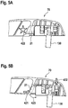
- the Figures 5A to 5D show the solution and release of a wiper blade 2 using the coupling device according to embodiments of the invention.
- the wiper blade 2 has a fastening part 30 at the head end 70.
- the fastening part includes a cavity and an opening 210.
- a fastening element 50 is provided on the drive shaft 130.
- the fastening element 50 includes, for example, the coupling element 21.
- the coupling element 21 is located in the guide element 210 of the fastening element 50, as in FIG Figure 5A shown.
- the rotationally rigid connection of fastening element 50 and fastening part 30 through the coupling element and the guide element is in Figure 5A schematically illustrated by the star 422.
- the stop between the start of the fastening element 50 and the contact position in the fastening part 30 forms a second contact point.
- Figure 5B shows a rotation of the guide element 210 in the direction 423, which can be caused by a torque on the wiper arm. If the torque exceeds the defined torque value, the guide element exerts such a force on the coupling element that the rotation brings about compression of a force-generating element, in particular a spring on the coupling element 21, as is the case, for example Figure 3 is shown.
- the compression of the force generating element is in the direction of arrow 421 in Figure 4B shown. Due to the movement of the coupling element 21 in the direction 421 caused by the compression in the direction 421, the coupling element 21 slips out of the guide element 210.
- the resulting instability of the position of the fastening part 30 with respect to the fastening element 50 can also lead to a release of the contact at the stop, in particular to a release of the fastening part 30 from the stop, as indicated by arrow 432.
- Figure 5C shows the progressive detachment of the wiper arm with fastening part 30 from the fastening element 50, the functional connection between the drive shaft and the wiper arm also being released.
- Figure 5D shows the wiper arm with fastener 30 and the fastener completely detached from each other.
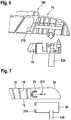
- Figure 6 shows an embodiment of a windshield wiper device in a form in which the wiper arm with the fastening part 30 at the head end 70 of the fastening element 50 is released by exceeding the defined torque value.
- the wiper arm in particular at the head end, comprises a return element 180, which holds the wiper arm on the vehicle, for example, in order to prevent the (uncontrolled) loss of the wiper arm.
- Figure 7 shows a further embodiment of the windshield wiper device according to the invention.
- the coupling element 21 is located in the wiper arm, in particular in the fastening part 30 of the wiper arm, in order to provide a safety coupling for a windshield wiper device.
- the fastening element 50 can comprise the guide element 210 of the coupling device.
- the wiper arm or the wiper blade can be particularly reliably protected against damage if an unusually high (i.e. outside of normal operation) torque acts on the wiper arm.
- the wiper arm can be easily made available, for example the wiper or the windshield wiper device, which is mounted on a vehicle, consists exclusively of plastic.
- the windshield wiper device can be provided without metal parts and / or without mechanical elements.
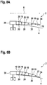
- FIGS 8A and 8B show schematic representations of a wiper blade 2 in a basic position and in a position applied to a window according to embodiments of the window wiper device of the disclosure.
- the wiper blade 2 is used to wipe a window 4 of a vehicle, which is, for example, a motor vehicle, in particular a car.
- the wiper blade 2 has a longitudinal extension 8 and has an elongated upper part 10 and a likewise elongated lower part 12.
- the longitudinal extensions of the upper part 10 and the lower part 12 essentially correspond to the longitudinal extension 8 of the wiper blade 2.
- Both the upper part 10 and the lower part 12 are bendable beams or can be designed as bendable beams. It is also possible to design only a part of the upper part 10 and / or the lower part 12 to be bendable. According to some Embodiments that can be combined with the other embodiments described here, a material is used for the upper part 10 and / or the lower part 12, which has a modulus of elasticity in a range between 0.005 kN / mm 2 and 0.5 kN / mm 2 , in particular 0.01 kN / mm 2 and 0.1 kN / mm 2 . This enables the upper part 10 and the lower part 12 to be suitably bent. Together with a suitably designed cross-sectional area of the upper part 10 and the lower part 12, this results in an optimal bending stiffness.
- the upper part 10 and the lower part 12 are fastened to a fastening part 30.
- the windshield wiper device can be connected by means of the fastening part 30 to a Quickfix fastening on the vehicle, for example.
- the upper part 10 and the lower part 12 are connected at a connection position 34.
- the connecting elements are designed such that the distance between the connecting position and the upper part and the distance between the connecting position and the lower part change by a maximum of ⁇ 1 mm, in particular by a maximum of +. 0.3 mm changes (for example due to thermal expansion and / or tension and compression).
- the connecting elements can thus be essentially non-elastic or the effect of the connecting elements is based on their force transmission between the upper part and lower part and not on their elasticity.
- the upper part 10 and the lower part 12 are connected to one another by connecting elements 18.
- the connecting elements 18 are fastened to mutually facing inner longitudinal sides of the upper part 10 and the lower part 12 by means of swivel joints 20.
- the pivots are 20 hinges.
- the swivel joints 20 can be designed as film hinges. This is particularly advantageous if the upper part 10, the lower part 12 and / or the connecting elements 18 are made of a plastic material or are coated with a suitable plastic material.
- a swivel joint is selected from the following group, which consists of: a hinge, a film hinge, a tapering of the material to produce less rigidity along a torsion axis, a joint with an axis of rotation, a means for connecting the upper part to the connecting element or for connecting the Lower part with the connecting element, which allows the displacement of the lower part with respect to the upper part along the longitudinal extent, etc.
- Embodiments in which the joints are provided by film hinges thus provide a very simple way of making the joints available for a fin ray wiper.
- the wiper blade 2 can be made available in one piece, in particular using tools.
- the film hinges have high extensibility. This can be provided, for example, by a material selected from the group PP, PE, POM, and PA.
- the film hinges can be made from one or more materials from a group consisting of: TPE (thermoplastic elastomer), for example TPE-S, TPE-O, TPE-U, TPE-A, TPE-V and TPE-E.
- the connecting elements 18 are spaced apart from one another along the longitudinal extent of the wiper blade 2.
- the distances are advantageously less than 50 mm, in particular less than 30 mm. This allows a particularly high flexibility of the windshield wiper device, in particular its lower part, and good adaptation to the curvature and changes in curvature of the windshield to be wiped.
- Figure 8B shows a schematic representation of the wiper blade 2 according to Figure 8A in a position applied to the disc 4. Since the washer 4 has a curvature, contact pressure forces act on the lower part 12 when the wiper blade 2 is applied to the washer 4 Upper part 10 and the lower part 12 are displaceable against each other. Due to the compressive forces acting on the lower part 12 from below, the wiper blade 2 bends in the direction from which the compressive forces come and lies precisely on the curvature of the disc 4.
- a windshield wiper device uses the effect of tail fins of certain fish which do not deflect in the direction of pressure under lateral pressure, but bulge in the opposite direction, ie in the direction from which the pressure comes. This principle is also referred to as the fin ray principle or "fin ray" principle.
- a windshield wiper device has the advantage of improved adaptation to a windshield of a motor vehicle.
- its upper part is usually rigid, ie it is not designed to be bendable.
- FIGs 9 and 10 show schematic representations of a wiper blade 2 of a windshield wiper device for a vehicle, in particular for a motor vehicle, in a basic position ( Figure 9 ), ie in an unloaded state, and in a position applied to a disc 4 ( Figure 10 ) according to the embodiments described herein.
- the wiper blade 2 comprises an elongated upper part 10 and an elongated lower part 12, which are designed to be at least partially bendable. Furthermore, a plurality of connecting elements 18 are provided for connecting the upper part 10 and the lower part 12, the connecting elements 18 being spaced apart from one another along a longitudinal extent 8 of the wiper blade 2.
- the connecting elements 18 are designed to allow the upper part 10 and the lower part 12 to move relative to one another with a movement component along a longitudinal extension 8 of the wiper blade 2. Furthermore, the connecting elements 18 are arranged relative to the lower part 12 such that in an unloaded state of the wiper blade 2 an angle ⁇ n of the respective longitudinal axes 24 of the connecting elements 18 relative to the lower part 12 changes at least partially along a longitudinal extension 8 of the wiper blade 2, in particular continuously changed or changed monotonously or strictly monotonously.
- Wiper blade shown in the unloaded state are the angles ⁇ n of the respective longitudinal axes of the connecting elements 18 relative to the lower part 12, which change along the longitudinal extent 8 of the wiper blade 2, with ⁇ 1 , ⁇ 2 , ⁇ 3 , ... ⁇ n-1 , denotes ⁇ n .
- a loaded state of the wiper blade ie in a position applied to the window, as exemplified in Fig. 10 is shown, the angles ⁇ n of the respective longitudinal axes 24 of the connecting elements 18 change relative to the lower part 12 compared to the unloaded state.
- angles ⁇ n of the respective longitudinal axes of the connecting elements are 18 relative to the lower part 12, which change along the longitudinal extent 8 of the wiper blade 2, in the in Fig. 2 shown wiper blade, which is located in a position applied to the window, with ⁇ ' 1 , ⁇ ' 2 , ⁇ ' 3 , ... ⁇ ' n-1 , ⁇ ' n .
- the wiper blade 2 has at least a first region in which the angle ⁇ n of the longitudinal axes 24 of the connecting elements 18 relative to the lower part 12 along a longitudinal extension 8 of the wiper blade 2 toward a wiper blade end decreases, especially monotonous, especially strictly monotonous, decreases. Furthermore, the wiper blade 2 can have at least one second region in which the angle ⁇ n of the longitudinal axes 24 of the connecting elements 18 relative to the lower part 12 increases along a longitudinal extension 8 of the wiper blade 2 towards a wiper blade end, in particular monotonously, in particular strictly monotonously.
- the second region of the wiper blade in which the angle ⁇ n of the longitudinal axes 24 of the connecting elements 18 relative to the lower part 12 increases along the longitudinal extension 8 of the wiper blade 2 towards an end of the wiper blade, is arranged at an inner position of the wiper blade, which is in the Located near a fastening device 30 of the wiper blade.
- a windshield wiper device can be made available which enables particularly good adaptation to the curvature of a windshield.
- a largely uniform contact pressure of the windshield wiper device on the windshield as well as a homogeneous force distribution of the windshield wiper device can be provided, so that a high wiping quality is provided.
- the connecting elements 18, in particular in an unloaded state of the wiper blade 2 are fastened to the lower part 12 such that the longitudinal axes 24 of the connecting elements 18 run at angles ⁇ n to the lower part 12, which lie between a lower angle limit value ⁇ nu and an upper limit value ⁇ no .
- the connecting elements 18 are configured such that the distance between the upper part 10 and the lower part 12 changes at least partially along a longitudinal extent 8 of the wiper blade 2, in particular continuously in a first region reduced and continuously enlarged in a second area.
- the distance between the upper part 10 and the lower part 12 along the longitudinal extension 8 of the wiper blade 2 can also include a range in which the distance between the upper part 10 and the lower part 12 along the longitudinal extension 8 of the wiper blade 2 is essentially constant.
- the distance between the upper part 10 and the lower part 12 is greater at the fastening part than at the opposite end.
- the inner distance value (facing the fastening part) is at least 15 mm, in particular at least 25 mm, in particular at least 35 mm.
- the outer distance value is at least 10 mm, in particular at least 12.5 mm, in particular at least 15 mm.
- the average distance value is at least 7.5 mm, in particular at least 9 mm, in particular at least 12.5 mm.
- the connecting elements 18 are connected in an articulated manner to the lower part 12 and / or the upper part 10 in accordance with embodiments which can be combined with other embodiments.
- the connecting elements 18 are connected to the lower part 12 and / or the upper part 10 by means of a first film hinge 20.
- the first film hinge 20 can be formed in one piece with the connecting element 18 and the upper part 10 and / or the lower part 12. The one-piece design of the film hinges allows simple and inexpensive production.
- the wiper blade comprises a first region with a first curvature ⁇ ⁇ 0 and a second region with a second curvature ⁇ > 0. Furthermore, the wiper blade according to embodiments have a third region with a third curvature ⁇ ⁇ 0, the second region of the wiper blade with the second curvature ⁇ > 0 being arranged between the first region with the first curvature ⁇ ⁇ 0 and the third region with the third curvature ⁇ ⁇ 0, as exemplified in Fig. 9 is shown.
- a windshield wiper device can be provided with which a largely uniform contact pressure on the windshield 4 can be achieved.
- a windshield wiper device can be provided which has an improved adaptation to the windshield 4 and a high wiping quality.
- a mechanism can be provided to wiper blade 2 Lift off the windshield wiper device from the windshield 4 or place it on it. This further simplifies use, for example for manual cleaning of the pane 2.
- FIG 11 describes a method for limiting a torque acting on a wiper arm of a windshield wiper device.
- a fastener that is attachable to a drive shaft of a vehicle is provided (see 802).
- a wiper blade with a fastening part, which can be detachably connected to the fastening element is provided (see 804).
- the method also includes assembling the wiper arm fastener to the fastener (see 806).
- the assembly is carried out by means of a coupling device, the assembly producing a connection, which is rotationally rigid up to a defined torque of the wiper blade, between the fastening element and the fastening part of the wiper arm.
- the fastening element, the wiper blade with fastening part and the coupling device can be the embodiments of the components described above.
- the windshield wiper device can, in particular, be a windshield wiper device that works according to the Finray principle, a fastening part on the wiper blade side being made available by a cavity with an opening as a guide element.
- the coupling element is typically pressed against the guide element by a force generating element, in particular a spring, at torques below the defined torque value.
Description
Die Erfindung betrifft eine Scheibenwischvorrichtung für ein Fahrzeug, insbesondere ein Kraftfahrzeug.The invention relates to a windshield wiper device for a vehicle, in particular a motor vehicle.
Scheibenwischvorrichtungen haben typischerweise einen Wischarm oder Wischhebel, wobei ein Wischblatt auf der Scheibe eines Kraftfahrzeugs bewegt wird. Dabei wird das Wischblatt zwischen einer ersten Wendelage und einer zweiten Wendelage bewegt. Zu diesem Zweck ist der Wischarm über die Antriebswelle mit einem Wischermotor verbunden. Insbesondere auf Windschutzscheiben mit starken Krümmungsänderungen und bei großen Temperaturschwankungen verliert das Wischblatt leicht den Kontakt zur Scheibe. Hierdurch kann es, insbesondere bei stark gekrümmten Scheiben, zu ungewischten Wischbereichen bzw. zu Schleierbildung kommen.Windshield wiper devices typically have a wiper arm or wiper lever, with a wiper blade being moved on the window of a motor vehicle. The wiper blade is moved between a first turning position and a second turning position. For this purpose, the wiper arm is connected to a wiper motor via the drive shaft. The wiper blade easily loses contact with the windscreen, particularly on windshields with large changes in curvature and with large temperature fluctuations. This can lead to unwiped wiping areas or fog, especially in the case of strongly curved panes.
Da ein Wischvorgang auf eine Vielzahl von Parametern optimiert werden muss, wie zum Beispiel eine Regenmenge auf der Scheibe, eine eventuell auftretende Schneelast auf der Scheibe, die Geschwindigkeit des Fahrzeugs und damit einhergehender Winddruck auf den Wischarm, kann eine Schleierbildung nicht auf einfache Weise durch Anpassung des Drucks des Wischarms auf die Windschutzscheibe zuverlässig verhindert werden. Daher ist es ein Bedürfnis, Scheibenwischvorrichtungen weiter zu verbessern.Since a wiping process has to be optimized for a variety of parameters, such as the amount of rain on the windshield, a possible snow load on the windshield, the speed of the vehicle and the associated wind pressure on the wiper arm, it is not easy to create a fog by adjusting the pressure of the wiper arm on the windshield can be reliably prevented. Therefore, there is a need to further improve windshield wipers.
Bei der Verbesserung gibt es eine Mehrzahl von Randbedingungen, die zusätzlich berücksichtigt werden sollten. Dabei ist es auch ein Bedürfnis, die Sicherheit der Handhabung und die Benutzerfreundlichkeit zu gewährleisten bzw. zu verbessern. Aus der
Es ist die Aufgabe der vorliegenden Erfindung, ein zuverlässiges, weitgehend schlierenfreies Wischen einer Scheibe eines Fahrzeugs zur Verfügung zu stellen und/oder eine zuverlässige Scheibenwischvorrichtung mit einfacher Handhabung, insbesondere einfacher Montage bzw. Demontage, zur Verfügung zu stellen, die eine Beschädigung der Scheibenwischvorrichtung auch bei höheren Lasten verhindert.It is the object of the present invention to provide a reliable, largely streak-free wiping of a windshield of a vehicle and / or to provide a reliable wiping device with simple handling, in particular simple assembly and disassembly, which also damage the wiping device prevented at higher loads.
Diese Aufgabe wird gelöst durch eine Scheibenwischvorrichtung mit den Merkmalen gemäß Anspruch 1.This object is achieved by a windshield wiper device with the features according to
Gemäß einer Ausführungsform wird eine Scheibenwischvorrichtung für ein Fahrzeug mit einem an einer Antriebswelle befestigten Befestigungselement, insbesondere ein Kraftfahrzeug, zur Verfügung gestellt. Die Scheibenwischvorrichtung beinhaltet ein Wischblatt mit einem langgestreckten Oberteil, das zumindest teilweise biegbar ausgestaltet ist, einem langgestreckten Unterteil, das zumindest teilweise biegbar ausgestaltet ist, und mehreren Verbindungselementen zum Verbinden des Oberteils und des Unterteils, wobei die Verbindungselemente entlang einer Längserstreckung des Wischblatts voneinander beabstandet sind, und wobei die Verbindungselemente ausgelegt sind, um eine Bewegung des Oberteils und des Unterteils relativ zueinander mit einer Bewegungskomponente entlang einer Längserstreckung des Wischblatts zu ermöglichen. Die Scheibenwischvorrichtung beinhaltet weiterhin ein wischblattseitiges Befestigungsteil, wobei das wischblattseitige Befestigungsteil an dem Befestigungselement lösbar verbindbar ist, und eine Kupplungsvorrichtung, wobei das wischblattseitige Befestigungsteil und das Befestigungselement durch die Kupplungsvorrichtung bis zu einem Überschreiten eines definierten Drehmomentwerts rotationssteif verbindbar sind.According to one embodiment, a windshield wiper device for a vehicle is provided with a fastening element, in particular a motor vehicle, fastened to a drive shaft. The windshield wiper device includes a wiper blade with an elongated upper part which is at least partially bendable, an elongated lower part which is at least partially bendable, and a plurality of connecting elements for connecting the upper part and the lower part, the connecting elements being spaced apart from one another along a longitudinal extent of the wiper blade , and wherein the connecting elements are designed to allow movement of the upper part and the lower part relative to one another with a movement component along a longitudinal extension of the wiper blade. The windshield wiper device further includes a wiper blade-side fastening part, the wiper blade-side fastening part being releasably connectable to the fastening element, and a coupling device, the wiper blade-side fastening part and the fastening element being rotationally rigidly connectable by the coupling device until a defined torque value is exceeded.
Bevorzugte Ausführungsformen und besondere Aspekte der Erfindung ergeben sich aus den abhängigen Ansprüchen, den Zeichnungen und der vorliegenden Beschreibung.Preferred embodiments and special aspects of the invention result from the dependent claims, the drawings and the present description.
Gemäß den hier beschriebenen Ausführungsformen der Erfindung können Scheibenwischvorrichtungen für Fahrzeuge mit einer Überlastsicherheitsvorrichtung auf besonders günstige Weise und für eine Mehrzahl unterschiedlicher Einsatzgebiete einfach bereitgestellt und montiert werden. Weiterhin ermöglichen die Ausführungsformen der Erfindung ein zuverlässiges, weitgehend schlierenfreies Wischen einer Scheibe eines Fahrzeugs.According to the embodiments of the invention described here, windshield wiper devices for vehicles with an overload safety device can be provided and assembled in a particularly advantageous manner and for a plurality of different areas of use. Furthermore, the embodiments of the invention enable a reliable, largely streak-free wiping of a window of a vehicle.
Gemäß einer Ausführungsform wird eine Scheibenwischvorrichtung für ein Fahrzeug mit einem an einer Antriebswelle befestigten Befestigungselement, insbesondere ein Kraftfahrzeug, zur Verfügung gestellt. Die Scheibenwischvorrichtung beinhaltet ein Wischblatt mit einem langgestreckten Oberteil, das zumindest teilweise biegbar ausgestaltet ist, einem langgestreckten Unterteil, das zumindest teilweise biegbar ausgestaltet ist, und mehreren Verbindungselementen zum Verbinden des Oberteils und des Unterteils, wobei die Verbindungselemente entlang einer Längserstreckung des Wischblatts voneinander beabstandet sind, und wobei die Verbindungselemente ausgelegt sind, um eine Bewegung des Oberteils und des Unterteils relativ zueinander mit einer Bewegungskomponente entlang einer Längserstreckung des Wischblatts zu ermöglichen. Die Scheibenwischvorrichtung beinhaltet weiterhin ein wischblattseitiges Befestigungsteil, wobei das wischblattseitige Befestigungsteil an dem Befestigungselement lösbar verbindbar ist, und eine Kupplungsvorrichtung, wobei das wischblattseitige Befestigungsteil und das Befestigungselement bis zu einem Überschreiten eines definierten Drehmomentwerts durch die Kupplungsvorrichtung rotationssteif verbindbar sind. Hierdurch kann ein Befestigungskonzept für eine Scheibenwischvorrichtung zur Verfügung gestellt werden, das die Antriebswelle während des Normalbetriebes rotationsfest mit dem Wischarm verbindet und gleichzeitig eine Beschädigung des Wischarms bei übermäßigen Belastungen des Wischarms verhindert.According to one embodiment, a windshield wiper device for a vehicle is provided with a fastening element, in particular a motor vehicle, fastened to a drive shaft. The windshield wiper device includes a wiper blade with an elongated upper part which is at least partially bendable, an elongated lower part which is at least partially bendable, and a plurality of connecting elements for connecting the upper part and the lower part, the connecting elements being spaced apart from one another along a longitudinal extent of the wiper blade , and wherein the connecting elements are designed to allow movement of the upper part and the lower part relative to one another with a movement component along a longitudinal extension of the wiper blade. The windshield wiper device further includes a wiper blade-side fastening part, the wiper blade-side fastening part being releasably connectable to the fastening element, and a coupling device, the wiper blade-side fastening part and the fastening element being rotationally rigidly connectable by the coupling device until a defined torque value is exceeded. In this way, a fastening concept for a windshield wiper device can be made available, which is the drive shaft connects to the wiper arm in a rotationally fixed manner during normal operation and at the same time prevents damage to the wiper arm in the event of excessive loads on the wiper arm.
Gemäß einer weiteren bevorzugten Ausführungsform ist bei Überschreiten des definierten Drehmomentwertes das wischblattseitige Befestigungsteil von dem Befestigungselement lösbar, wobei insbesondere bei Überschreiten des definierten Drehmomentwertes das wischblattseitige Befestigungsteil von dem Befestigungselement freigegeben wird. Dadurch wird eine zuverlässige Trennung der betroffenen Komponenten erreicht und eine Beschädigung der Komponenten durch hohe Drehzahlbelastungen verhindert.According to a further preferred embodiment, the fastening element on the wiper blade side can be detached from the fastening element when the defined torque value is exceeded, the fastening element being released from the fastening element in particular when the defined torque value is exceeded. This ensures a reliable separation of the affected components and prevents damage to the components due to high speed loads.
Gemäß der Erfindung beinhaltet die Scheibenwischvorrichtung weiterhin das Befestigungselement, wobei die Kupplungsvorrichtung insbesondere ein Kupplungselement umfasst, das am Befestigungselement angebracht ist und sich bei Erreichen des definierten Drehmomentwertes bewegt. Durch die Bereitstellung eines beweglichen Kupplungselements am Befestigungselement kann der Wischarm und das Befestigungsteil des Wischarms sehr einfach und kostengünstig konstruiert und produziert werden. In einem Beispiel kann das Befestigungsteil des Wischarms zur Befestigung am Befestigungselement außerdem eine Kavität aufweisen, die Kontaktflächen für das Befestigungselement vorsieht. Damit kann der Wischarm einfach und kostengünstig montiert werden, während die Funktion des beweglichen Kupplungselements im Befestigungselement bleibt.According to the invention, the windshield wiper device further includes the fastening element, the coupling device in particular comprising a coupling element which is attached to the fastening element and moves when the defined torque value is reached. By providing a movable coupling element on the fastening element, the wiper arm and the fastening part of the wiper arm can be constructed and produced very simply and inexpensively. In one example, the fastening part of the wiper arm for fastening to the fastening element can also have a cavity which provides contact surfaces for the fastening element. This allows the wiper arm to be installed simply and inexpensively while the function of the movable coupling element remains in the fastening element.
Gemäß einer weiteren bevorzugten Ausführungsform stellt die Kupplungsvorrichtung bei Drehmomentwerten unter dem definierten Drehmomentwert einen Kraft-und/oder Formschluss zwischen dem Befestigungselement und dem Befestigungsteil des Wischarms her. Dadurch kann eine rotationssteife Verbindung zwischen dem Befestigungselement und dem Befestigungsteil bereitgestellt werden, und insbesondere die Rotation der Antriebswelle, an der das Befestigungselement befestigbar ist, auf das Wischblatt übertragen werden.According to a further preferred embodiment, the coupling device produces a force and / or positive connection between the fastening element and the fastening part of the wiper arm at torque values below the defined torque value. As a result, a rotationally rigid connection can be provided between the fastening element and the fastening part, and in particular the rotation of the drive shaft, to which the fastening element can be fastened, is transmitted to the wiper blade.
Gemäß einer weiteren bevorzugten Ausführungsform weist die Kupplungsvorrichtung ein Kupplungselement mit einem Radius und ein an dem Kupplungselement bei Drehmomenten unter dem definierten Drehmoment zumindest teilweise anliegendes Führungselement auf, wobei insbesondere das Kupplungselement am Befestigungselement angebracht ist und das Führungselement an dem Befestigungsteil des Wischarms angebracht ist. Dies stellt eine einfache und zuverlässige Realisierung der Drehmomentbegrenzung unter Berücksichtigung von baulichen Gegebenheiten und vorteilhaften Ausführungsformen des Befestigungsteils und des Befestigungselements dar.According to a further preferred embodiment, the coupling device has a coupling element with a radius and a guide element which is at least partially applied to the coupling element at torques below the defined torque, in particular the coupling element on the fastening element is attached and the guide element is attached to the fastening part of the wiper arm. This represents a simple and reliable implementation of the torque limitation, taking into account structural conditions and advantageous embodiments of the fastening part and the fastening element.
Gemäß einer weiteren bevorzugten Ausführungsform kann durch das an dem Kupplungselement anliegende Führungselement eine rotationssteife Verbindung zwischen dem Befestigungselement und dem Befestigungsteil hergestellt werden. Dabei ist es vorteilhaft, dass sowohl die stabile Abstützung des Befestigungsteils des Wischblattes am Befestigungselement als auch die Kupplungsfunktion von dem Kupplungselement und dem Führungselement zur Verfügung gestellt werden können.According to a further preferred embodiment, a rotationally rigid connection between the fastening element and the fastening part can be produced by the guide element resting on the coupling element. It is advantageous that both the stable support of the fastening part of the wiper blade on the fastening element and the coupling function of the coupling element and the guide element can be provided.
Gemäß einer weiteren bevorzugten Ausführungsform umfasst die Kupplungsvorrichtung weiterhin ein Krafterzeugungselement, insbesondere eine Feder, das an dem Kupplungselement angebracht ist. Durch ein Krafterzeugungselement an dem Kupplungselement kann das Kupplungselement bis zu einer bestimmten Kraft oder einem bestimmten Moment, das auf das Krafterzeugungselement wirkt, in einer stabilen Position gehalten werden.According to a further preferred embodiment, the coupling device further comprises a force generating element, in particular a spring, which is attached to the coupling element. By means of a force generating element on the coupling element, the coupling element can be held in a stable position up to a specific force or a specific moment which acts on the force generating element.
Gemäß einer weiteren bevorzugten Ausführungsform sind das Kupplungselement und das Führungselement ausgelegt, dass das Kupplungselement mit Radius bei Erreichen des definierten Drehmoments durch das Führungselement rutscht und dabei insbesondere die rotationssteife Verbindung zwischen Befestigungselement und Befestigungsteil löst. Das Durchrutschen des Kupplungselements kann insbesondere durch die gegenseitige Auslegung des Kupplungselementradius und des Führungselements hervorgerufen werden. Dabei kann zum Beispiel ein entsprechend ausgelegtes Krafterzeugungselement die Drehmomentgrenze mitbestimmen, bei der das Kupplungselement durch das Führungselement rutscht. Dies stellt eine einfach zu realisierende und zuverlässige Art dar, das Sicherheitskonzept der hierin beschriebenen Ausführungsformen umzusetzen.According to a further preferred embodiment, the coupling element and the guide element are designed in such a way that the coupling element with a radius slips through the guide element when the defined torque is reached and in particular releases the rotationally rigid connection between the fastening element and the fastening part. The slipping of the coupling element can be caused in particular by the mutual design of the coupling element radius and the guide element. In this case, for example, an appropriately designed force generating element can also determine the torque limit at which the coupling element slips through the guide element. This is an easy to implement and reliable way to implement the security concept of the embodiments described herein.
Gemäß einer weiteren bevorzugten Ausführungsform umfasst die Kupplungsvorrichtung eine Rutschkupplung. Durch die Verwendung einer Rutschkupplung werden weitere sicherheitsrelevante Aspekte miteinbezogen, insbesondere wird nachAccording to a further preferred embodiment, the coupling device comprises a slip clutch. Through the use of a slip clutch, further safety-relevant aspects are included, in particular the following
Überschreiten des Drehmomentgrenzwertes der Wischarm nicht von dem Befestigungselement gelöst, sondern lediglich die Kraftübertragung zwischen Antriebswelle und Wischarm unterbrochen.If the torque limit value of the wiper arm is not released from the fastening element, only the power transmission between the drive shaft and the wiper arm is interrupted.
Gemäß einer weiteren bevorzugten Ausführungsform ist das wischblattseitige Befestigungsteil einteilig ausgebildet, wobei das wischblattseitige Befestigungsteil insbesondere angepasst ist, um mittels eines Spritzgussverfahrens, insbesondere eines Spritzgussverfahrens mit einem Schritt zur Verfügung gestellt zu werden. Diese Ausführungsformen ermöglichen eine einfache und kostengünstige Herstellung des Befestigungsteils des Wischblattes.According to a further preferred embodiment, the wiper blade-side fastening part is formed in one piece, the wiper blade-side fastening part being in particular adapted to be made available in one step by means of an injection molding method, in particular an injection molding method. These embodiments enable simple and inexpensive production of the fastening part of the wiper blade.
Gemäß einer weiteren bevorzugten Ausführungsform weist das wischblattseitige Befestigungsteil eine Kavität auf, wobei sich in dieser Kavität ein Führungselement der Kupplungsvorrichtung befindet, und wobei das wischblattseitige Befestigungsteil insbesondere weiterhin einen Kontaktpunkt aufweist. Dies stellt eine zuverlässige rotationssteife Befestigung des Befestigungsteils und des Befestigungselements dar.According to a further preferred embodiment, the wiper blade-side fastening part has a cavity, in which cavity there is a guide element of the coupling device, and the wiper blade-side fastening part in particular furthermore has a contact point. This represents a reliable rotationally rigid fastening of the fastening part and the fastening element.
Gemäß einer weiteren bevorzugten Ausführungsform kann das wischblattseitige Befestigungsteil metall-frei und/oder ohne bewegliche Elemente ausgebildet sein. Dies kann ebenfalls einer einfachen Ausgestaltung dienen. Zum Beispiel kann ein Wischblatt als Ersatzteil kostengünstig hergestellt werden.According to a further preferred embodiment, the fastening part on the wiper blade side can be designed to be metal-free and / or without movable elements. This can also serve a simple configuration. For example, a wiper blade can be manufactured inexpensively as a spare part.
Gemäß einer weiteren bevorzugten Ausführungsform kann das wischblattseitige Befestigungsteil ausgebildet sein, um eine Rotation relativ zum Befestigungselement um eine Achse senkrecht zur Längserstreckung des Wischblatts und senkrecht zur Antriebsachse relativ zum Befestigungselement bei einem Drehmoment kleiner als das definierte Drehmoment zu ermöglichen. Hierdurch kann ein definierter Anpressdruck einer Wischlippe an eine Scheibe zur Verfügung gestellt werden. Zum Beispiel kann gemäß weiteren Ausführungsformen die Rotation des Befestigungsteils relativ zum Befestigungselement in einem Winkelbereich von 30° oder kleiner beschränkt ist. Es handelt sich folglich nicht um eine Rotation, die einem abklappen des Wischblatts von der Scheibe entspricht.According to a further preferred embodiment, the wiper blade-side fastening part can be designed to enable rotation relative to the fastening element about an axis perpendicular to the longitudinal extension of the wiper blade and perpendicular to the drive axis relative to the fastening element with a torque smaller than the defined torque. In this way, a defined contact pressure of a wiper lip against a pane can be made available. For example, according to further embodiments, the rotation of the fastening part relative to the fastening element is restricted in an angular range of 30 ° or less. It is therefore not a matter of a rotation which corresponds to a folding down of the wiper blade from the window.
Gemäß einer weiteren bevorzugten Ausführungsform können die mehreren Verbindungselemente an mehreren oberen Verbindungspositionen mit dem Oberteil und an mehreren unteren korrespondierenden Verbindungspositionen mit dem Unterteil verbunden sein, wobei bei der Bewegung des Oberteils und des Unterteils relativ zueinander der Abstand zwischen einer oberen Verbindungspositionen und einer korrespondierenden unteren Verbindungsposition, im Wesentlichen konstant ist, insbesondere konstant ist mit einer Abweichung von ±1 mm. Hierdurch kann eine Kraftübertragung zwischen dem Oberteil und dem Unterteil zur Verfügung gestellt werden, die eine Scheibenwischvorrichtung ermöglicht, die gemäß dem Finray-Prinzip arbeitet.According to a further preferred embodiment, the plurality of connection elements can be connected to the upper part and at a plurality of upper connection positions be connected to the lower part at a plurality of lower corresponding connection positions, the distance between an upper connection position and a corresponding lower connection position being substantially constant, in particular constant with a deviation of ± 1 mm, when the upper part and the lower part move relative to one another. In this way, a power transmission between the upper part and the lower part can be made available, which enables a windshield wiper device that works according to the finray principle.
Gemäß einer weiteren nicht beanspruchten Ausführungsform wird ein Verfahren zum Begrenzen eines Drehmoments, das auf einem Wischarm einer Scheibenwischvorrichtung wirkt, bereitgestellt. Das Verfahren beinhaltet das Bereitstellen eines Befestigungselements, das an einer Antriebswelle eines Fahrzeugs befestigbar ist; und das Bereitstellen eines Wischblattes mit Befestigungsteil, das mit dem Befestigungselement lösbar verbindbar ist. Das Verfahren umfasst weiterhin das Zusammenfügen des Befestigungsteils des Wischarms mit dem Befestigungselement mittels einer Kupplungsvorrichtung, insbesondere einer Kupplungsvorrichtung mit einem Kupplungselement und einem Führungselement, wobei durch das Zusammenfügen eine bis zu einem definierten Drehmoment des Wischblatts rotationssteife Verbindung zwischen dem Befestigungselement und dem Befestigungsteil des Wischarms hergestellt wird. Es kann somit ein Sicherheitskonzept für eine Scheibenwischvorrichtung bereitgestellt werden, das eine Beschädigung des Wischblattes bei hoher Drehmomentbelastung verhindert. In einem Beispiel kann das Verfahren weiterhin das Drücken des Kupplungselements gegen das Führungselement durch ein Krafterzeugungselement, insbesondere eine Feder umfassen. Dadurch wird ein sicherer Sitz während des Normalbetriebes, d.h. ohne Einfluss eines hohen Drehmoments auf den Wischarm gewährleistet.According to a further embodiment, a method for limiting a torque acting on a wiper arm of a windshield wiper device is provided. The method includes providing a fastener that is attachable to a drive shaft of a vehicle; and the provision of a wiper blade with fastening part, which is releasably connectable to the fastening element. The method further comprises assembling the fastening part of the wiper arm with the fastening element by means of a coupling device, in particular a coupling device with a coupling element and a guide element, whereby the joining produces a connection which is rotationally rigid up to a defined torque of the wiper blade between the fastening element and the fastening part of the wiper arm becomes. A safety concept for a windshield wiper device can thus be provided which prevents damage to the wiper blade under high torque loads. In one example, the method can further include pressing the coupling element against the guide element by a force generating element, in particular a spring. This ensures a secure fit during normal operation, i.e. guaranteed without the influence of high torque on the wiper arm.
Ausführungsbeispiele der Erfindung sind in den Figuren dargestellt und werden im Folgenden näher beschrieben. Es zeigen:
-
Figur 1 -
Figur 2 -
Figur 3 -
Figur 4A eine schematische Darstellung eines Eingriffs eines Teils eines Kupplungselements mit einem Führungselement eines wischblattseitigen Befestigungsteils gemäß einer Ausführungsform der Erfindung, -
Figur 4B eine schematische Darstellung eines Ausschnitts eines Kupplungselements und eines Führungselements gemäß einer Ausführungsform der Erfindung, -
Figur 4C eine schematische Darstellung des wischblattseitigen Befestigungsteils gemäß einer Ausführungsform der Erfindung, -
Figuren 5A bis 5D eine schematische Darstellung der Funktionsweise einer Kupplungsvorrichtung einer Scheibenwischvorrichtung gemäß einer Ausführungsform der Erfindung, -
Figur 6 eine schematische Darstellung eines Befestigungsteils und eines Befestigungselements einer Scheibenwischvorrichtung gemäß einer Ausführungsform der Erfindung, -
Figur 7 eine schematische Darstellung eines Befestigungsteils und eines Befestigungselements einer Scheibenwischvorrichtung gemäß einer Ausführungsform der Erfindung, -
Figur 8A eine schematische Darstellung eines weiteren Ausführungsbeispiels einer erfindungsgemäßen Scheibenwischvorrichtung in Form eines Wischerarms mit integriertem Wischblatt in einer Grundstellung, -
Figur 8B eine schematische Darstellung des Wischerarms mit integriertem Wischblatt nachFig. 8A in einer an eine Scheibe angelegten Stellung, -
Figur 9 eine schematische Darstellung eines Wischblatts gemäß Ausführungsformen vorliegenden Erfindung in einer Grundstellung, -
Figur 10 -
Figur 11 ein Diagramm zur Illustration eines Verfahrens zum Begrenzen eines Drehmoments, das auf einem Wischarm einer Scheibenwischvorrichtung wirkt gemäß Ausführungsformen der vorliegenden Erfindung.
-
Figure 1 1 shows a schematic illustration of a part of a wiper blade in a longitudinal sectional view, -
Figure 2 2 shows a schematic illustration of a part of a wiper blade in a longitudinal sectional view according to an embodiment of the invention, a fastening part on the wiper blade side being fastened to a fastening element, -
Figure 3 2 shows a schematic cross-sectional view from above of a windshield wiper device with a coupling device according to an embodiment of the invention, -
Figure 4A -
Figure 4B -
Figure 4C -
Figures 5A to 2 shows a schematic illustration of the functioning of a coupling device of a windshield wiper device according to an embodiment of the invention,5D -
Figure 6 1 shows a schematic illustration of a fastening part and a fastening element of a windshield wiper device according to one embodiment of the invention, -
Figure 7 1 shows a schematic illustration of a fastening part and a fastening element of a windshield wiper device according to one embodiment of the invention, -
Figure 8A -
Figure 8B is a schematic representation of the wiper arm with integrated wiper bladeFigure 8A in a position applied to a disc, -
Figure 9 1 shows a schematic illustration of a wiper blade according to embodiments of the present invention in a basic position, -
Figure 10 a schematic representation of a wiper blade according to embodiments of the present invention in a position applied to a window, and -
Figure 11 10 is a diagram illustrating a method for limiting a torque acting on a wiper arm of a windshield wiper device according to embodiments of the present invention.
Im Folgenden werden, sofern nicht anders vermerkt, für gleiche und gleichwirkende Elemente gleiche Bezugszeichen verwendet.Unless otherwise noted, the same reference symbols are used below for the same and equivalent elements.
Zum Beispiel ist an den Verbindungspositionen jeweils ein Drehgelenk zur Verfügung gestellt. Bei einer Bewegung des Oberteils 10 des Unterteil 12 relativ zueinander verändert sich der Abstand einer oberen Verbindungsposition zu einer unteren Verbindungsposition am selben Verbindungselement im Wesentlichen nicht, d.h. der Abstand ist mit Abweichungen von zum Beispiel ±1 mm, insbesondere ±0,3 mm konstant.For example, a swivel joint is provided at the connection positions. When the
Weiter hat das Wischblatt 2 ein Kopfende 70. Am Kopfende ist ein Befestigungsteil 30, d.h. ein wischblattseitiges Befestigungsteil 30, zur Verfügung gestellt. Entlang der Längserstreckung des Wischblatts 2 wird der Abstand zwischen dem Oberteil 10 und dem Unterteil 12 ausgehend vom Kopfende kleiner, zumindest in Bereichen der Längserstreckung des Wischblatts bzw. in einem überwiegenden Teil der Längserstreckung des Wischblatts. Ausgehend vom Kopfende läuft die Höhe des Wischblatts in Bereichen keilförmig zu bzw. wird in Bereichen der Längserstreckung kleiner. Zum Beispiel kann gemäß Ausführungsformen für eine Mehrzahl der Verbindungselemente die Länge der Verbindungselemente derart zur Verfügung gestellt werden, dass die am Kopfende zur Verfügung gestellten Verbindungselemente länger sind als die an der gegenüberliegenden Seite des Wischblatts entlang der Längserstreckung.Furthermore, the
Durch diese Eigenschaften kann eine Scheibenwischvorrichtung zur Verfügung gestellt werden, die nach dem Finray-Prinzip funktioniert. Diese Scheibenwischvorrichtungen haben typischerweise kein Gelenk um das Wischblatt oder eine Wischlippe von einer Scheibe, zum Beispiel einer Scheibe eines Kraftfahrzeugs, abzuheben. Zum Beispiel wird das Wischblatts 2 mittels eines Schnellverschlusses (Quickfix) von einem an einer Antriebswelle 130 zur Verfügung gestellten Befestigungselement 50 gelöst.These properties make it possible to provide a windshield wiper device that works according to the finray principle. These windshield wiper devices typically have no joint in order to lift the wiper blade or a wiper lip off a window, for example a window of a motor vehicle. For example, the
Das Wischblatt 2 beinhaltet ein Oberteil 12 ein Unterteil 10 und mehrere Verbindungselemente 18. Das Befestigungsteil 30 beinhaltet eine Kavität und eine Öffnung 210. Die Kavität ist eingerichtet, um das Befestigungselement 50 aufzunehmen. Die Öffnung 210 ist angepasst, so dass ein Kupplungselement 21 einer Kupplungsvorrichtung in die Öffnung eingeführt werden kann. Die Öffnung 210 kann auch als Führungselement einer Kupplungsvorrichtung bezeichnet werden. In einer Ausführungsform bietet die Öffnung 210 ein Auflager 230, wobei der untere Bereich der Bereich der Öffnung 210 ist, der einer Scheibe zugewandt ist.The
Die in der in
Dabei wird durch die Verwendung einer erfindungsgemäßen Scheibenwischvorrichtung gemäß hierin beschriebener Ausführungsformen die Beschädigung eines Schiebenwischarms, z.B. durch Schneelasten, Vandalismus, oder dergleichen verhindert.The use of a windshield wiper device according to the invention in accordance with the embodiments described herein damages the sliding wiper arm, e.g. prevented by snow loads, vandalism, or the like.
Gemäß Ausführungsformen der vorliegenden Erfindung wird eine Rotationsposition um eine Achse senkrecht zur Längserstreckung des Wischblatts und senkrecht zur Achse der Antriebswelle (oder senkrecht zur linearen Montagerichtung) durch einen ersten Kontaktpunkt und einen zweiten Kontaktpunkt zwischen dem wischblattseitigen Befestigungsteil 30 und im Befestigungselement 50 festgelegt. Die Lage des Wischblatts 2 wird somit definiert ohne überbestimmt zu sein.According to embodiments of the present invention, a rotational position about an axis perpendicular to the longitudinal extension of the wiper blade and perpendicular to the axis of the drive shaft (or perpendicular to the linear mounting direction) is defined by a first contact point and a second contact point between the wiper blade-
In einer Ausführungsformen der vorliegenden Erfindung wird der erste Kontaktpunkt durch ein Führungselement der Kupplungsvorrichtung zur Verfügung gestellt, das zwischen der Rotationsachse der Antriebswelle 130 und einem Verbindungselement 18 zur Verfügung gestellt ist, und der zweite Kontaktpunkt durch einen Anschlag, der zum Beispiel auf der gegenüberliegenden Seite der Antriebswelle 130 zur Verfügung gestellt ist.In one embodiment of the present invention, the first contact point is provided by a guide element of the coupling device, which is provided between the axis of rotation of the
Gemäß Ausführungsformen der vorliegenden Erfindung kann der Anschlag 232, der am Befestigungselement 50 zur Verfügung gestellt ist, um mit einer entsprechenden Position des Befestigungsteils 30 die Rotationsposition zu definieren, an einem beweglichen Element 254 zur Verfügung gestellt werden. Das bewegliche Element 254 kann zum Beispiel ein in einer Führung beweglicher Pin sein. Die Bewegung des beweglichen Elements 254 kann durch eine Feder 252 definiert werden, die eine Kraft für den Anschlag 232 aufbringt. Verstärkt sich zum Beispiel eine Kraft, die beim Wischen des Wischblatts 2 auf das Unterteil 10 wirkt, wird über den Hebel der Anschlag 232 nach unten bewegt, das heißt die Feder 252 wird mit einer stärkeren Kraft belastet. Das bewegliche Element 254 bewegt sich nach unten. Der Anschlag 232 hat hierbei eine variable Position, wobei ein Hebel um das Auflager 230 existiert.According to embodiments of the present invention, the
Gemäß manchen Ausführungsformen, die mit anderen Ausführungsformen kombiniert werden können, kann eine auf die Unterseite des Wischblatts bzw. eine an der Unterseite befestigten Wischlippe wirkenden Kraft von 2 Newton bis 10 Newton, zum Beispiel ungefähr 5 Newton, über einen Hebelverhältnis einer Federkraft von 8 Newton bis 40 Newton, ungefähr 20 Newton entsprechen.According to some embodiments, which can be combined with other embodiments, a force acting on the underside of the wiper blade or a wiper lip attached to the underside can be from 2 Newtons to 10 Newtons, for example approximately 5 Newtons, via a lever ratio of a spring force of 8 Newtons up to 40 newtons, approximately 20 newtons.
Gemäß noch weiteren Ausführungsformen, die mit anderen Ausführungsformen kombiniert werden können, kann ein Befestigungselement 50 auch ohne Feder ausgestaltet werden. Hierbei wird durch den Anschlag 232 eine feste Rotationsposition zur Verfügung gestellt. Es wird aus dem beweglichen Element 254 ein festes Element. Gemäß noch weiteren Ausführungsformen, kann die Position des Anschlags durch unterschiedliche Längen dieses festen Elements bzw. durch unterschiedliche Adapter bzw. Aufsätze auf das feste Element zur Verfügung gestellt werden. Es kann durch diese vordefinierte Variation des Anschlags bzw. des Kontaktpunkts zum Beispiel die Verwendung einer Scheibenwischvorrichtung auf einem spezifischen Fahrzeugtyp eingestellt werden.According to still further embodiments, which can be combined with other embodiments, a
Wie oben beschrieben wird durch das Führungselement, das während des Normalbetriebes zum Beispiel ein Auflager bereitstellen kann, und einen Anschlag, das heißt einen ersten Kontaktpunkt und einen zweiten Kontaktpunkt, eine Rotationsposition um eine Achse senkrecht zur Längserstreckung des Wischblatts und senkrecht zur Achse der Antriebswelle in Abhängigkeit einer Kraft auf das Wischblatt zur Verfügung gestellt. In Abhängigkeit der Kraft kann das Wischblatt im Normalbetrieb um eine Achse senkrecht zur Längserstreckung des Wischblatts und senkrecht zur Achse der Antriebswelle rotieren. Gemäß einer Ausführungsform der Erfindung stellt das Kupplungselement 21, wie in
Gemäß einer Ausführungsform kann der definierte Drehmomentwert in einem Bereich von ungefähr 4 Nm bis ungefähr 50 Nm liegen, insbesondere in einem Bereich von ungefähr 10 Nm bis ungefähr 25 Nm.According to one embodiment, the defined torque value can be in a range from approximately 4 Nm to approximately 50 Nm, in particular in a range from approximately 10 Nm to approximately 25 Nm.
Die
Gemäß manchen Ausführungsformen kann das Befestigungsteil 30 bzw. das Wischblatt 20 dadurch zur Verfügung gestellt werden, das mechanische Elemente wie Federn, Federelemente, Betätigungsvorrichtung und/oder metallische Elemente nicht in dem Befestigungsteil 30 sondern in einem korrespondierenden Befestigungselement 50 zur Verfügung gestellt werden. Das Befestigungsteil 30 ist somit angepasst, um in einem Spritzgussverfahren, insbesondere einem einfachen Spritzgussverfahren bzw. einem Spritzgussverfahren mit einem Schritt zur Verfügung gestellt zu werden. Zum Beispiel besteht das Befestigungselement 30 lediglich aus einem Material. Das Befestigungselement 30 hat eine Öffnung 210 und eine Kavität. Optional können in dem einen Material Ausformungen wie Führungsschienen oder eine Kontaktposition zur Verfügung gestellt werden.According to some embodiments, the
Die
Während des Normalbetriebes (wie in
Im Folgenden werden Aspekte einer beispielhaften Scheibenwischvorrichtung beschrieben, für welche die hierin beschriebenen Ausführungsformen der Scheibenwischvorrichtung, insbesondere mit der beschriebenen Sicherheitskupplung als Kupplungsvorrichtung vorteilhaft sind. Der Wischarm bzw. das Wischblatt können dabei besonders zuverlässig vor Beschädigung geschützt werden, wenn ein ungewöhnlich hohes (d.h. außerhalb des Normalbetriebs liegendes) Drehmoment auf den Wischarm wirkt. Zudem kann der Wischarm einfach zur Verfügung gestellt werden, wobei zum Beispiel der Wischer bzw. die Scheibenwischvorrichtung, die an einem Fahrzeug montiert wird, ausschließlich aus Kunststoff besteht. Zum Beispiel kann die Scheibenwischvorrichtung ohne Metallteile und/oder ohne mechanische Elemente zur Verfügung gestellt werden.Aspects of an exemplary windshield wiper device are described below, for which the embodiments of the windshield wiper device described here, in particular with the described safety clutch as a coupling device, are advantageous. The wiper arm or the wiper blade can be particularly reliably protected against damage if an unusually high (i.e. outside of normal operation) torque acts on the wiper arm. In addition, the wiper arm can be easily made available, for example the wiper or the windshield wiper device, which is mounted on a vehicle, consists exclusively of plastic. For example, the windshield wiper device can be provided without metal parts and / or without mechanical elements.
Sowohl das Oberteil 10 als auch das Unterteil 12 sind biegbare Balken oder können als biegbare Balken ausgestaltet sein Es ist ebenso möglich, nur jeweils einen Teil des Oberteils 10 und/oder des Unterteils 12 biegbar auszugestalten. Gemäß manchen Ausführungsformen, die mit den anderen hier beschriebenen Ausführungsformen kombiniert werden können, wird für das Oberteil 10 und/oder das Unterteil 12 ein Material eingesetzt, das einen Elastizitätsmodul hat, der in einem Bereich zwischen 0,005 kN/mm2 und 0,5 kN/mm2, insbesondere 0,01 kN/mm2 und 0,1 kN/mm2, liegt. Dies ermöglicht eine geeignete Biegefähigkeit des Oberteils 10 und des Unterteils 12. Zusammen mit einer geeignet ausgestalteten Querschnittsfläche des Oberteils 10 und des Unterteils 12 ergibt sich so eine optimale Biegesteifigkeit.Both the
Das Oberteil 10 und das Unterteil 12 sind an einem Befestigungsteil 30 befestigt. Die Scheibenwischvorrichtung kann mittels des Befestigungsteils 30 zum Beispiel mit einer Quickfix-Befestigung am Fahrzeug verbunden sein. An der Seite, die dem Befestigungsteil 30 entlang der Längserstreckung der Scheibenwischvorrichtung gegenüberliegt, ist das Oberteil 10 und das Unterteil 12 an einer Verbindungsposition 34 verbunden. Die Verbindungselemente sind derart ausgestaltet, dass sich der Abstand der Verbindungsposition mit dem Oberteil und der Abstand der Verbindungsposition mit dem Unterteil um maximal ±1 mm ändert, insbesondere um maximal +. 0,3 mm ändert (zum Beispiel durch Wärmeausdehnung und/oder Zug und Druckbelastung). Die Verbindungselemente können somit im Wesentlichen nicht elastisch ausgebildet bzw. der Effekt der Verbindungselemente beruht auf deren Kraftübertragung zwischen Oberteil und Unterteil und nicht auf deren Elastizität.The
Das Oberteil 10 und das Unterteil 12 sind durch Verbindungselemente 18 miteinander verbunden. Die Verbindungselemente 18 sind an einander zugewandten inneren Längsseiten des Oberteils 10 und des Unterteils 12 mittels Drehgelenken 20 befestigt. Typischerweise sind die Drehgelenke 20 Scharniere. Insbesondere können die Drehgelenke 20 als Filmscharniere ausgebildet sein. Dies ist vor allem dann vorteilhaft, wenn das Oberteil 10, das Unterteil 12 und/oder die Verbindungselemente 18 aus einem Kunststoffmaterial hergestellt oder mit einem geeigneten Kunststoffmaterial überzogen sind.The
Gemäß typischen hier beschriebenen Ausführungsformen, die mit anderen hier beschriebenen Ausführungsformen kombiniert werden können, ist ein Drehgelenk aus der folgenden Gruppe ausgewählt, die besteht aus: einem Scharnier, einem Filmscharnier, einer Verjüngung des Materials zur Erzeugung geringerer Steifigkeit entlang einer Torsionsachse, einem Gelenk mit einer Rotationsachse, einem Mittel zur Verbindung des Oberteils mit dem Verbindungselement oder zur Verbindung des Unterteils mit dem Verbindungselement, das die Verschiebung des Unterteils in Bezug auf das Oberteil entlang der Längserstreckung erlaubt, etc.According to typical embodiments described here, which can be combined with other embodiments described here, a swivel joint is selected from the following group, which consists of: a hinge, a film hinge, a tapering of the material to produce less rigidity along a torsion axis, a joint with an axis of rotation, a means for connecting the upper part to the connecting element or for connecting the Lower part with the connecting element, which allows the displacement of the lower part with respect to the upper part along the longitudinal extent, etc.
Ausführungsformen, bei denen die Gelenke durch Filmscharniere zur Verfügung gestellt sind, stellen somit eine sehr einfache Art und Weise zur Verfügung, um die Gelenke für einen Fin-Ray-Wischer zur Verfügung zu stellen. Das Wischblatt 2 kann einteilige, insbesondere werkzeugfallend, zur Verfügung gestellt werden. Gemäß typischen Ausführungsformen haben die Filmscharniere eine hohe Dehnbarkeit. Dies kann zum Beispiel durch ein Material ausgewählt aus der Gruppe PP, PE, POM, und PA, zur Verfügung gestellt werden. Alternativ können die Filmscharniere aus einem oder mehreren Materialen aus einer Gruppe bestehend aus: TPE (Thermoplastischem Elastomer), beispielsweise TPE-S, TPE-O, TPE-U, TPE-A TPE-V und TPE-E hergestellt sein.Embodiments in which the joints are provided by film hinges thus provide a very simple way of making the joints available for a fin ray wiper. The
Die Verbindungselemente 18 sind entlang der Längserstreckung des Wischblatts 2 voneinander beabstandet. Die Abstände sind vorteilhafterweise kleiner als 50 mm, insbesondere kleiner als 30 mm. Dadurch kann eine besonders hohe Flexibilität der Scheibenwischvorrichtung, insbesondere ihres Unterteils, und gute Anpassung an die Krümmung und Krümmungsänderungen der zu wischenden Scheibe gewährleistet werden.The connecting
Durch den Aufbau der hier beschriebenen Ausführungsformen, findet bei einer Krafteinwirkung auf das Unterteil (durch die Scheibe 4) eine Biegung des Unterteils in die Richtung statt, aus der die Kraft wirkt. Dies ist durch die Verbindung des Oberteils 10 und des Unterteils an der Verbindungsposition 34, die Form, und durch Drehgelenke an der Verbindung zwischen den Verbindungselementen und dem Ober- bzw. Unterteil gegeben. Eine Scheibenwischvorrichtung gemäß hier beschriebener Ausführungsformen nutzt den Effekt von Schwanzflossen bestimmter Fische, die bei seitlichem Druck nicht in Druckrichtung ausweichen, sondern sich in entgegengesetzte Richtung wölben, d. h. in die Richtung, aus der der Druck kommt. Dieses Prinzip wird auch als Flossenstrahl-Prinzip oder "Fin Ray"-Prinzip bezeichnet. Dadurch hat eine Scheibenwischvorrichtung gemäß den hierin beschriebenen Ausführungsformen den Vorteil einer verbesserten Anpassung an eine Scheibe eines Kraftfahrzeugs. Bei einem herkömmlichen Scheibenwischblatt ist dessen Oberteil üblicherweise starr, d. h. es ist nicht biegbar ausgebildet.Due to the structure of the embodiments described here, when the force acts on the lower part (through the disk 4), the lower part bends in the direction from which the force acts. This is due to the connection of the
In dem in
Gemäß Ausführungsformen der Scheibenwischvorrichtung, welche mit anderen Ausführungsformen kombiniert werden können, weist das Wischblatt 2 zumindest einen ersten Bereich auf, in dem der Winkel αn der Längsachsen 24 der Verbindungselemente 18 relativ zum Unterteil 12 entlang einer Längserstreckung 8 des Wischblatts 2 zu einem Wischblattende hin abnimmt, insbesondere monoton, insbesondere streng monoton, abnimmt. Ferner kann das Wischblatt 2 zumindest einen zweiten Bereich aufweisen, in dem der Winkel αn der Längsachsen 24 der Verbindungselemente 18 relativ zum Unterteil 12 entlang einer Längserstreckung 8 des Wischblatts 2 zu einem Wischblattende hin zunimmt, insbesondere monoton, insbesondere streng monoton, zunimmt. Gemäß Ausführungsformen, wie beispielhaft in den
Gemäß Ausführungsformen des Wischblatts, welche mit anderen Ausführungsformen kombiniert werden können, sind die Verbindungselemente 18, insbesondere in einem unbelastetem Zustand des Wischblatts 2, so an dem Unterteil 12 befestigt, dass die Längsachsen 24 der Verbindungselemente 18 in Winkeln αn zum Unterteil 12 verlaufen, die zwischen einem unteren Winkelgrenzwert αnu und einem oberen Grenzwert αno liegen. Gemäß Ausführungsformen, ist der untere Winkelgrenzwert αnu = 10°, insbesondere αnu = 15°, insbesondere αnu = 20° und der obere Winkelgrenzwert αno = 80°, insbesondere αno = 90° insbesondere αno = 100°. Dies gewährleistet vorteilhafterweise eine besonders gute Übertragung einer auf das Unterteil wirkenden Kraft auf das Oberteil.According to embodiments of the wiper blade, which can be combined with other embodiments, the connecting
Gemäß Ausführungsformen der Scheibenwischvorrichtung, welche mit anderen Ausführungsformen kombiniert werden können, sind die Verbindungselemente 18 derart konfiguriert sind, dass sich der Abstand zwischen dem Oberteil 10 und dem Unterteil 12 zumindest teilweise entlang einer Längserstreckung 8 des Wischblatts 2 verändert, insbesondere in einem ersten Bereich stetig verkleinert und in einem zweiten Bereich stetig vergrößert. Der Abstand zwischen dem Oberteil 10 und dem Unterteil 12 entlang der Längserstreckung 8 des Wischblatts 2 kann auch einen Bereich umfassen, in welchem der Abstand zwischen dem Oberteil 10 und dem Unterteil 12 entlang der Längserstreckung 8 des Wischblatts 2 im Wesentlichen konstant ist. Der Abstand zwischen dem Oberteil 10 und dem Unterteil 12 ist am Befestigungsteil größer als am gegenüberliegenden Ende.According to embodiments of the windshield wiper device, which can be combined with other embodiments, the connecting
Gemäß Ausführungsformen des Wischblatts, welche mit anderen Ausführungsformen kombiniert werden können, beträgt der innere (dem Befestigungsteil zugewandte) Abstandswert mindestens 15 mm, insbesondere mindestens 25 mm, insbesondere mindestens 35 mm. Gemäß Ausführungsformen, welche mit anderen Ausführungsformen kombiniert werden können, beträgt der äußere Abstandswert mindestens 10 mm, insbesondere mindestens 12,5 mm, insbesondere mindestens 15 mm. Gemäß Ausführungsformen, welche mit anderen Ausführungsformen kombiniert werden können, beträgt der mittlere Abstandswert mindestens 7,5 mm, insbesondere mindestens 9 mm, insbesondere mindestens 12,5 mm.According to embodiments of the wiper blade, which can be combined with other embodiments, the inner distance value (facing the fastening part) is at least 15 mm, in particular at least 25 mm, in particular at least 35 mm. According to embodiments which can be combined with other embodiments, the outer distance value is at least 10 mm, in particular at least 12.5 mm, in particular at least 15 mm. According to embodiments which can be combined with other embodiments, the average distance value is at least 7.5 mm, in particular at least 9 mm, in particular at least 12.5 mm.
Wie in den
Gemäß Ausführungsformen des Wischblatts, welche mit anderen hierin beschriebenen Ausführungsformen kombiniert werden können, umfasst das Wischblatt einen ersten Bereich mit einer ersten Krümmung ω<0 und einen zweiten Bereich mit einer zweiten Krümmung ω>0. Ferner kann das Wischblatt gemäß Ausführungsformen einen dritten Bereich mit einer dritten Krümmung ω<0 aufweisen, wobei der zweite Bereich des Wischblatts mit der zweiten Krümmung ω>0 zwischen dem ersten Bereich mit der ersten Krümmung ω<0 und dem dritten Bereich mit der dritten Krümmung ω<0 angeordnet ist, wie es beispielhaft in
Gemäß weitern Ausführungsformen kann zusätzlich zu einem für Fin-Ray-Wischer verwendbaren Quickfix-Befestigungsverschluss, bei dem die gesamte Scheibenwischvorrichtung von einer Antriebsachse bzw. einem Befestigungselement an der Antriebsachse am Fahrzeug entfernt wird, einen Mechanismus zur Verfügung gestellt werden, um das Wischblatt 2 einer Scheibenwischvorrichtung von der Scheibe 4 abzuheben bzw. auf diese aufzusetzen. Dies vereinfacht weiter die Benutzung, zum Beispiel für eine manuelle Reinigung der Scheibe 2.According to further embodiments, in addition to a quick-fix fastening fastener which can be used for fin-ray wipers and in which the entire windshield wiper device is removed from a drive axle or a fastening element on the drive axle on the vehicle, a mechanism can be provided to
In
Claims (12)
- Windscreen wiper device (100) for a vehicle with a fastening element (50) fixed on a drive shaft, more particularly for a motor vehicle, comprising a wiper blade (2) with- an elongated upper part (10), which is configured at least partially flexibly,- an elongated lower part (12), which is configured at least partially flexibly,- several connecting elements (18) for connecting the upper part (10) and the lower part (12), wherein the connecting elements (18) are spaced apart from one another along a longitudinal extension (8) of the wiper blade (2), and wherein the connecting elements (18) are designed in order to enable a movement of the upper part (10) and the lower part relative to one another with a component of movement along a longitudinal extension (8) of the wiper blade (2),- a fastening part (30) on the wiper blade side wherein the fastening part (30) on the wiper blade side is detachably connectable to the fastening element (50), and- a coupling device, characterized in that the fastening part (30) on the wiper blade side and the fastening element (50) are connectable to one another for conjoint rotation until a defined torque value is exceeded, and are completely releasable from one another, by means of the coupling device, wherein the fastening element (50) and the coupling device comprise in particular a coupling element (21) which is attached to the fastening element (50) and is moved when the defined torque value is reached.
- Windscreen wiper device according to Claim 1, wherein when the defined torque value is exceeded the fastening part (30) on the wiper blade side is releasable from the fastening element (50), wherein more particularly when the defined torque value is exceeded the fastening part on the wiper blade side is released from the fastening element.
- Windscreen wiper device (100) according to one of Claims 1 to 2, wherein the coupling device in the event of torque values up to a defined torque value produces a force-fitting and/or form-fitting connection between the fastening element (50) and the fastening part (30).
- Windscreen wiper device according to one of Claims 1 to 3, wherein the coupling device has a coupling element (21) with a radius and a guide element (210) bearing at least partially on the coupling element (21) in the event of torques below the defined torque, wherein in particular the coupling element (21) is attached to the fastening element (50) and the guide element (210) is attached to the fastening part (30) of the wiper arm.
- Windscreen wiper device according to Claim 4, wherein a connection between the fastening element (50) and the fastening part (30) for conjoint rotation can be produced by the guide element (210) which bears against the coupling element (21).
- Windscreen wiper device according to one of Claims 1 to 5, wherein the coupling device furthermore comprises a force-producing element (211), more particularly a spring, wherein the force-producing element (211) is in particular attached to the coupling element (21).
- Windscreen wiper device according to one of Claims 3 to 6, wherein the coupling element (21) and the guide element (210) are designed so that the coupling element (21) with radius slips through the guide element (210) when the defined torque is reached and can then in particular release the rotationally secured connection between the fastening element (50) and fastening part (30) .
- Windscreen wiper device according to one of Claims 1 to 7, wherein the defined torque lies in a range from approximately 4 Nm to approximately 50 Nm, more particularly in a range from approximately 10 Nm to approximately 25 Nm.
- Windscreen wiper device according to one of Claims 1, wherein the coupling device comprises a slip coupling and wherein in particular when the defined torque value is exceeded the functional connection between the drive shaft (130) and the fastening part (30) of the wiper arm is released.
- Windscreen wiper device according to one of Claims 1 to 9, wherein the fastening part (30) on the wiper blade side is formed in one piece.
- Windscreen wiper device according to one of Claims 1 to 10, wherein the fastening part (30) on the wiper blade side is formed free of metal and/or without movable elements.
- Windscreen wiper device (100) according to one of Claims 1 to 11, wherein the plurality of connecting elements (18) are connected at several upper connecting positions to the upper part (10) and at several lower corresponding connecting positions to the lower part (12), and wherein in the event of movement of the upper part (10) and the lower part (12) relative to one another the distance between an upper connecting position and a corresponding lower connecting position is substantially constant, more particularly is constant with a deviation of ± 1 mm.
Applications Claiming Priority (2)
| Application Number | Priority Date | Filing Date | Title |
|---|---|---|---|
| DE102014214560.0A DE102014214560A1 (en) | 2014-07-24 | 2014-07-24 | Safety coupling for finray wiper |
| PCT/EP2015/065784 WO2016012262A1 (en) | 2014-07-24 | 2015-07-10 | Safety coupling for fin ray wiper |
Publications (2)
| Publication Number | Publication Date |
|---|---|
| EP3172096A1 EP3172096A1 (en) | 2017-05-31 |
| EP3172096B1 true EP3172096B1 (en) | 2020-03-11 |
Family
ID=53610866
Family Applications (1)
| Application Number | Title | Priority Date | Filing Date |
|---|---|---|---|
| EP15738302.7A Active EP3172096B1 (en) | 2014-07-24 | 2015-07-10 | Safety coupling for fin ray wiper |
Country Status (6)
| Country | Link |
|---|---|
| US (1) | US10427649B2 (en) |
| EP (1) | EP3172096B1 (en) |
| CN (1) | CN106660521B (en) |
| DE (1) | DE102014214560A1 (en) |
| FR (1) | FR3024101A1 (en) |
| WO (1) | WO2016012262A1 (en) |
Family Cites Families (15)
| Publication number | Priority date | Publication date | Assignee | Title |
|---|---|---|---|---|
| GB433731A (en) * | 1933-12-23 | 1935-08-20 | Sev Marchal | Improvements in wind shield cleaners |
| US2142054A (en) * | 1935-08-30 | 1938-12-27 | Trico Products Corp | Windshield cleaner |
| US2808596A (en) * | 1954-07-22 | 1957-10-08 | Norval P Schreiner | Ventilated mattress quilt |
| FR2382357A1 (en) * | 1977-03-01 | 1978-09-29 | Cibie Projecteurs | Snap fastening for windscreen wiper arm - has sprung retainer inside slotted drive stub to press arm over projection |
| US6026536A (en) * | 1997-10-09 | 2000-02-22 | Lear Automotive Dearborn, Inc | Range limiting dual direction slip clutch |
| FR2879540B1 (en) * | 2004-12-17 | 2008-07-11 | Valeo Systemes Dessuyage | DEBRAYABLE CONNECTION ARRANGEMENT OF ICE WIPER ARM ON MOTOR SHAFT |
| US8042219B2 (en) * | 2006-10-30 | 2011-10-25 | Federal-Mogul World Wide, Inc. | Wiper arm assembly having locking surfaces |
| FR2931762B1 (en) * | 2008-05-30 | 2010-06-11 | Valeo Systemes Dessuyage | DEBRAYABLE DRIVE MECHANISM OF A WIPING SYSTEM FOR A MOTOR VEHICLE, AND CORRESPONDING TRAINING HEAD |
| JP2010089574A (en) * | 2008-10-06 | 2010-04-22 | Mitsuba Corp | Wiper arm |
| US20100089576A1 (en) * | 2008-10-08 | 2010-04-15 | Potter Drilling, Inc. | Methods and Apparatus for Thermal Drilling |
| KR101356153B1 (en) * | 2011-12-08 | 2014-01-29 | 현대자동차주식회사 | Wiper device for vehicle |
| CN102555998B (en) * | 2012-03-28 | 2014-11-05 | 张正生 | Automotive windshield wiper |
| DE102013214064A1 (en) * | 2012-11-07 | 2014-05-08 | Robert Bosch Gmbh | Windscreen wiper device for a vehicle |
| WO2015007350A1 (en) * | 2013-07-17 | 2015-01-22 | Robert Bosch Gmbh | Windcreeen wiper device for a vehicle |
| DE102013224029A1 (en) * | 2013-11-25 | 2015-05-28 | Robert Bosch Gmbh | Removable windshield wiper device for manual windscreen cleaning |
-
2014
- 2014-07-24 DE DE102014214560.0A patent/DE102014214560A1/en not_active Withdrawn
-
2015
- 2015-07-10 WO PCT/EP2015/065784 patent/WO2016012262A1/en active Application Filing
- 2015-07-10 CN CN201580040113.7A patent/CN106660521B/en active Active
- 2015-07-10 EP EP15738302.7A patent/EP3172096B1/en active Active
- 2015-07-10 US US15/328,486 patent/US10427649B2/en active Active
- 2015-07-22 FR FR1556921A patent/FR3024101A1/en active Pending
Non-Patent Citations (1)
| Title |
|---|
| None * |
Also Published As
| Publication number | Publication date |
|---|---|
| WO2016012262A1 (en) | 2016-01-28 |
| CN106660521A (en) | 2017-05-10 |
| CN106660521B (en) | 2019-11-26 |
| US10427649B2 (en) | 2019-10-01 |
| FR3024101A1 (en) | 2016-01-29 |
| US20170210348A1 (en) | 2017-07-27 |
| DE102014214560A1 (en) | 2016-01-28 |
| EP3172096A1 (en) | 2017-05-31 |
Similar Documents
| Publication | Publication Date | Title |
|---|---|---|
| WO2015071104A1 (en) | Windscreen wiper device | |
| EP3044045B1 (en) | Fastening device for a windscreen wiping device | |
| EP3172095B1 (en) | Quick fastening for fin ray wipers | |
| WO2015071085A1 (en) | Windscreen wiper device | |
| EP3172096B1 (en) | Safety coupling for fin ray wiper | |
| EP3044051B1 (en) | Film hinge for a windscreen wiping device | |
| WO2016096401A1 (en) | Windshield wiper device | |
| WO2016012264A1 (en) | Fastening device for a windscreen wiping device | |
| EP3172098B1 (en) | Structural variants for fin ray wipers | |
| EP3224092B1 (en) | Fin ray wiper with replaceable wiper blade element | |
| EP3044047B1 (en) | Structural variants for fin ray wipers | |
| DE102013217945A1 (en) | Biasing device for a windshield wiper device | |
| WO2016020241A1 (en) | Fin ray wiper having a clamping device | |
| EP3044049B1 (en) | Windshield washer device having improved creep behavior | |
| WO2016012266A1 (en) | Windscreen wiper device | |
| EP3172097B1 (en) | Quick connecting device for fin ray wiper | |
| WO2015071163A1 (en) | Windshield wiper device | |
| WO2015180921A1 (en) | Spoiler for fin ray wiper | |
| EP3177490B1 (en) | Cover for a fin-ray wiper | |
| DE102014222981A1 (en) | Finray wiper with predetermined breaking point | |
| DE102014216665A1 (en) | Windscreen wiper device with clamping device | |
| WO2016012267A1 (en) | Pretensioning device for a windscreen wiping device |
Legal Events
| Date | Code | Title | Description |
|---|---|---|---|
| STAA | Information on the status of an ep patent application or granted ep patent |
Free format text: STATUS: THE INTERNATIONAL PUBLICATION HAS BEEN MADE |
|
| PUAI | Public reference made under article 153(3) epc to a published international application that has entered the european phase |
Free format text: ORIGINAL CODE: 0009012 |
|
| STAA | Information on the status of an ep patent application or granted ep patent |
Free format text: STATUS: REQUEST FOR EXAMINATION WAS MADE |
|
| 17P | Request for examination filed |
Effective date: 20170224 |
|
| AK | Designated contracting states |
Kind code of ref document: A1 Designated state(s): AL AT BE BG CH CY CZ DE DK EE ES FI FR GB GR HR HU IE IS IT LI LT LU LV MC MK MT NL NO PL PT RO RS SE SI SK SM TR |
|
| AX | Request for extension of the european patent |
Extension state: BA ME |
|
| DAV | Request for validation of the european patent (deleted) | ||
| DAX | Request for extension of the european patent (deleted) | ||
| STAA | Information on the status of an ep patent application or granted ep patent |
Free format text: STATUS: EXAMINATION IS IN PROGRESS |
|
| 17Q | First examination report despatched |
Effective date: 20181009 |
|
| GRAP | Despatch of communication of intention to grant a patent |
Free format text: ORIGINAL CODE: EPIDOSNIGR1 |
|
| STAA | Information on the status of an ep patent application or granted ep patent |
Free format text: STATUS: GRANT OF PATENT IS INTENDED |
|
| INTG | Intention to grant announced |
Effective date: 20191025 |
|
| GRAS | Grant fee paid |
Free format text: ORIGINAL CODE: EPIDOSNIGR3 |
|
| GRAA | (expected) grant |
Free format text: ORIGINAL CODE: 0009210 |
|
| STAA | Information on the status of an ep patent application or granted ep patent |
Free format text: STATUS: THE PATENT HAS BEEN GRANTED |
|
| AK | Designated contracting states |
Kind code of ref document: B1 Designated state(s): AL AT BE BG CH CY CZ DE DK EE ES FI FR GB GR HR HU IE IS IT LI LT LU LV MC MK MT NL NO PL PT RO RS SE SI SK SM TR |
|
| REG | Reference to a national code |
Ref country code: GB Ref legal event code: FG4D Free format text: NOT ENGLISH |
|
| REG | Reference to a national code |
Ref country code: CH Ref legal event code: EP |
|
| REG | Reference to a national code |
Ref country code: AT Ref legal event code: REF Ref document number: 1242761 Country of ref document: AT Kind code of ref document: T Effective date: 20200315 |
|
| REG | Reference to a national code |
Ref country code: IE Ref legal event code: FG4D Free format text: LANGUAGE OF EP DOCUMENT: GERMAN |
|
| REG | Reference to a national code |
Ref country code: DE Ref legal event code: R096 Ref document number: 502015011989 Country of ref document: DE |
|
| RAP2 | Party data changed (patent owner data changed or rights of a patent transferred) |
Owner name: ROBERT BOSCH GMBH |
|
| PG25 | Lapsed in a contracting state [announced via postgrant information from national office to epo] |
Ref country code: FI Free format text: LAPSE BECAUSE OF FAILURE TO SUBMIT A TRANSLATION OF THE DESCRIPTION OR TO PAY THE FEE WITHIN THE PRESCRIBED TIME-LIMIT Effective date: 20200311 Ref country code: NO Free format text: LAPSE BECAUSE OF FAILURE TO SUBMIT A TRANSLATION OF THE DESCRIPTION OR TO PAY THE FEE WITHIN THE PRESCRIBED TIME-LIMIT Effective date: 20200611 Ref country code: RS Free format text: LAPSE BECAUSE OF FAILURE TO SUBMIT A TRANSLATION OF THE DESCRIPTION OR TO PAY THE FEE WITHIN THE PRESCRIBED TIME-LIMIT Effective date: 20200311 |
|
| REG | Reference to a national code |
Ref country code: NL Ref legal event code: MP Effective date: 20200311 |
|
| PG25 | Lapsed in a contracting state [announced via postgrant information from national office to epo] |
Ref country code: BG Free format text: LAPSE BECAUSE OF FAILURE TO SUBMIT A TRANSLATION OF THE DESCRIPTION OR TO PAY THE FEE WITHIN THE PRESCRIBED TIME-LIMIT Effective date: 20200611 Ref country code: GR Free format text: LAPSE BECAUSE OF FAILURE TO SUBMIT A TRANSLATION OF THE DESCRIPTION OR TO PAY THE FEE WITHIN THE PRESCRIBED TIME-LIMIT Effective date: 20200612 Ref country code: HR Free format text: LAPSE BECAUSE OF FAILURE TO SUBMIT A TRANSLATION OF THE DESCRIPTION OR TO PAY THE FEE WITHIN THE PRESCRIBED TIME-LIMIT Effective date: 20200311 Ref country code: LV Free format text: LAPSE BECAUSE OF FAILURE TO SUBMIT A TRANSLATION OF THE DESCRIPTION OR TO PAY THE FEE WITHIN THE PRESCRIBED TIME-LIMIT Effective date: 20200311 Ref country code: SE Free format text: LAPSE BECAUSE OF FAILURE TO SUBMIT A TRANSLATION OF THE DESCRIPTION OR TO PAY THE FEE WITHIN THE PRESCRIBED TIME-LIMIT Effective date: 20200311 |
|
| REG | Reference to a national code |
Ref country code: LT Ref legal event code: MG4D |
|
| PG25 | Lapsed in a contracting state [announced via postgrant information from national office to epo] |
Ref country code: NL Free format text: LAPSE BECAUSE OF FAILURE TO SUBMIT A TRANSLATION OF THE DESCRIPTION OR TO PAY THE FEE WITHIN THE PRESCRIBED TIME-LIMIT Effective date: 20200311 |
|
| PG25 | Lapsed in a contracting state [announced via postgrant information from national office to epo] |
Ref country code: CZ Free format text: LAPSE BECAUSE OF FAILURE TO SUBMIT A TRANSLATION OF THE DESCRIPTION OR TO PAY THE FEE WITHIN THE PRESCRIBED TIME-LIMIT Effective date: 20200311 Ref country code: PT Free format text: LAPSE BECAUSE OF FAILURE TO SUBMIT A TRANSLATION OF THE DESCRIPTION OR TO PAY THE FEE WITHIN THE PRESCRIBED TIME-LIMIT Effective date: 20200805 Ref country code: LT Free format text: LAPSE BECAUSE OF FAILURE TO SUBMIT A TRANSLATION OF THE DESCRIPTION OR TO PAY THE FEE WITHIN THE PRESCRIBED TIME-LIMIT Effective date: 20200311 Ref country code: RO Free format text: LAPSE BECAUSE OF FAILURE TO SUBMIT A TRANSLATION OF THE DESCRIPTION OR TO PAY THE FEE WITHIN THE PRESCRIBED TIME-LIMIT Effective date: 20200311 Ref country code: SK Free format text: LAPSE BECAUSE OF FAILURE TO SUBMIT A TRANSLATION OF THE DESCRIPTION OR TO PAY THE FEE WITHIN THE PRESCRIBED TIME-LIMIT Effective date: 20200311 Ref country code: IS Free format text: LAPSE BECAUSE OF FAILURE TO SUBMIT A TRANSLATION OF THE DESCRIPTION OR TO PAY THE FEE WITHIN THE PRESCRIBED TIME-LIMIT Effective date: 20200711 Ref country code: SM Free format text: LAPSE BECAUSE OF FAILURE TO SUBMIT A TRANSLATION OF THE DESCRIPTION OR TO PAY THE FEE WITHIN THE PRESCRIBED TIME-LIMIT Effective date: 20200311 Ref country code: EE Free format text: LAPSE BECAUSE OF FAILURE TO SUBMIT A TRANSLATION OF THE DESCRIPTION OR TO PAY THE FEE WITHIN THE PRESCRIBED TIME-LIMIT Effective date: 20200311 |
|
| REG | Reference to a national code |
Ref country code: DE Ref legal event code: R097 Ref document number: 502015011989 Country of ref document: DE |
|
| PLBE | No opposition filed within time limit |
Free format text: ORIGINAL CODE: 0009261 |
|
| STAA | Information on the status of an ep patent application or granted ep patent |
Free format text: STATUS: NO OPPOSITION FILED WITHIN TIME LIMIT |
|
| PG25 | Lapsed in a contracting state [announced via postgrant information from national office to epo] |
Ref country code: ES Free format text: LAPSE BECAUSE OF FAILURE TO SUBMIT A TRANSLATION OF THE DESCRIPTION OR TO PAY THE FEE WITHIN THE PRESCRIBED TIME-LIMIT Effective date: 20200311 Ref country code: DK Free format text: LAPSE BECAUSE OF FAILURE TO SUBMIT A TRANSLATION OF THE DESCRIPTION OR TO PAY THE FEE WITHIN THE PRESCRIBED TIME-LIMIT Effective date: 20200311 Ref country code: IT Free format text: LAPSE BECAUSE OF FAILURE TO SUBMIT A TRANSLATION OF THE DESCRIPTION OR TO PAY THE FEE WITHIN THE PRESCRIBED TIME-LIMIT Effective date: 20200311 |
|
| 26N | No opposition filed |
Effective date: 20201214 |
|
| PG25 | Lapsed in a contracting state [announced via postgrant information from national office to epo] |
Ref country code: PL Free format text: LAPSE BECAUSE OF FAILURE TO SUBMIT A TRANSLATION OF THE DESCRIPTION OR TO PAY THE FEE WITHIN THE PRESCRIBED TIME-LIMIT Effective date: 20200311 Ref country code: SI Free format text: LAPSE BECAUSE OF FAILURE TO SUBMIT A TRANSLATION OF THE DESCRIPTION OR TO PAY THE FEE WITHIN THE PRESCRIBED TIME-LIMIT Effective date: 20200311 Ref country code: MC Free format text: LAPSE BECAUSE OF FAILURE TO SUBMIT A TRANSLATION OF THE DESCRIPTION OR TO PAY THE FEE WITHIN THE PRESCRIBED TIME-LIMIT Effective date: 20200311 |
|
| REG | Reference to a national code |
Ref country code: CH Ref legal event code: PL |
|
| GBPC | Gb: european patent ceased through non-payment of renewal fee |
Effective date: 20200710 |
|
| REG | Reference to a national code |
Ref country code: BE Ref legal event code: MM Effective date: 20200731 |
|
| PG25 | Lapsed in a contracting state [announced via postgrant information from national office to epo] |
Ref country code: GB Free format text: LAPSE BECAUSE OF NON-PAYMENT OF DUE FEES Effective date: 20200710 Ref country code: CH Free format text: LAPSE BECAUSE OF NON-PAYMENT OF DUE FEES Effective date: 20200731 Ref country code: LI Free format text: LAPSE BECAUSE OF NON-PAYMENT OF DUE FEES Effective date: 20200731 Ref country code: LU Free format text: LAPSE BECAUSE OF NON-PAYMENT OF DUE FEES Effective date: 20200710 |
|
| PG25 | Lapsed in a contracting state [announced via postgrant information from national office to epo] |
Ref country code: BE Free format text: LAPSE BECAUSE OF NON-PAYMENT OF DUE FEES Effective date: 20200731 |
|
| PG25 | Lapsed in a contracting state [announced via postgrant information from national office to epo] |
Ref country code: IE Free format text: LAPSE BECAUSE OF NON-PAYMENT OF DUE FEES Effective date: 20200710 |
|
| REG | Reference to a national code |
Ref country code: AT Ref legal event code: MM01 Ref document number: 1242761 Country of ref document: AT Kind code of ref document: T Effective date: 20200710 |
|
| PG25 | Lapsed in a contracting state [announced via postgrant information from national office to epo] |
Ref country code: AT Free format text: LAPSE BECAUSE OF NON-PAYMENT OF DUE FEES Effective date: 20200710 |
|
| PG25 | Lapsed in a contracting state [announced via postgrant information from national office to epo] |
Ref country code: TR Free format text: LAPSE BECAUSE OF FAILURE TO SUBMIT A TRANSLATION OF THE DESCRIPTION OR TO PAY THE FEE WITHIN THE PRESCRIBED TIME-LIMIT Effective date: 20200311 Ref country code: MT Free format text: LAPSE BECAUSE OF FAILURE TO SUBMIT A TRANSLATION OF THE DESCRIPTION OR TO PAY THE FEE WITHIN THE PRESCRIBED TIME-LIMIT Effective date: 20200311 Ref country code: CY Free format text: LAPSE BECAUSE OF FAILURE TO SUBMIT A TRANSLATION OF THE DESCRIPTION OR TO PAY THE FEE WITHIN THE PRESCRIBED TIME-LIMIT Effective date: 20200311 |
|
| PG25 | Lapsed in a contracting state [announced via postgrant information from national office to epo] |
Ref country code: MK Free format text: LAPSE BECAUSE OF FAILURE TO SUBMIT A TRANSLATION OF THE DESCRIPTION OR TO PAY THE FEE WITHIN THE PRESCRIBED TIME-LIMIT Effective date: 20200311 Ref country code: AL Free format text: LAPSE BECAUSE OF FAILURE TO SUBMIT A TRANSLATION OF THE DESCRIPTION OR TO PAY THE FEE WITHIN THE PRESCRIBED TIME-LIMIT Effective date: 20200311 |
|
| PGFP | Annual fee paid to national office [announced via postgrant information from national office to epo] |
Ref country code: FR Payment date: 20230724 Year of fee payment: 9 Ref country code: DE Payment date: 20230922 Year of fee payment: 9 |