EP1908630A2 - Headlight apparatus and vehice - Google Patents
Headlight apparatus and vehice Download PDFInfo
- Publication number
- EP1908630A2 EP1908630A2 EP07253679A EP07253679A EP1908630A2 EP 1908630 A2 EP1908630 A2 EP 1908630A2 EP 07253679 A EP07253679 A EP 07253679A EP 07253679 A EP07253679 A EP 07253679A EP 1908630 A2 EP1908630 A2 EP 1908630A2
- Authority
- EP
- European Patent Office
- Prior art keywords
- headlight
- flasher
- lens
- directional indicator
- disposed
- Prior art date
- Legal status (The legal status is an assumption and is not a legal conclusion. Google has not performed a legal analysis and makes no representation as to the accuracy of the status listed.)
- Withdrawn
Links
- 238000005192 partition Methods 0.000 claims abstract description 22
- 230000003287 optical effect Effects 0.000 claims description 9
- 238000000638 solvent extraction Methods 0.000 claims description 2
- 238000003754 machining Methods 0.000 description 2
- 238000010586 diagram Methods 0.000 description 1
- 238000004519 manufacturing process Methods 0.000 description 1
- 239000000463 material Substances 0.000 description 1
- 238000000034 method Methods 0.000 description 1
- 229920005989 resin Polymers 0.000 description 1
- 239000011347 resin Substances 0.000 description 1
- 230000035939 shock Effects 0.000 description 1
- 229920003002 synthetic resin Polymers 0.000 description 1
- 239000000057 synthetic resin Substances 0.000 description 1
- 239000013585 weight reducing agent Substances 0.000 description 1
Images

Classifications
-
- B—PERFORMING OPERATIONS; TRANSPORTING
- B60—VEHICLES IN GENERAL
- B60Q—ARRANGEMENT OF SIGNALLING OR LIGHTING DEVICES, THE MOUNTING OR SUPPORTING THEREOF OR CIRCUITS THEREFOR, FOR VEHICLES IN GENERAL
- B60Q1/00—Arrangement of optical signalling or lighting devices, the mounting or supporting thereof or circuits therefor
- B60Q1/0029—Spatial arrangement
- B60Q1/0041—Spatial arrangement of several lamps in relation to each other
-
- B—PERFORMING OPERATIONS; TRANSPORTING
- B62—LAND VEHICLES FOR TRAVELLING OTHERWISE THAN ON RAILS
- B62J—CYCLE SADDLES OR SEATS; AUXILIARY DEVICES OR ACCESSORIES SPECIALLY ADAPTED TO CYCLES AND NOT OTHERWISE PROVIDED FOR, e.g. ARTICLE CARRIERS OR CYCLE PROTECTORS
- B62J6/00—Arrangement of optical signalling or lighting devices on cycles; Mounting or supporting thereof; Circuits therefor
- B62J6/02—Headlights
- B62J6/022—Headlights specially adapted for motorcycles or the like
- B62J6/026—Headlights specially adapted for motorcycles or the like characterised by the structure, e.g. casings
-
- B—PERFORMING OPERATIONS; TRANSPORTING
- B62—LAND VEHICLES FOR TRAVELLING OTHERWISE THAN ON RAILS
- B62J—CYCLE SADDLES OR SEATS; AUXILIARY DEVICES OR ACCESSORIES SPECIALLY ADAPTED TO CYCLES AND NOT OTHERWISE PROVIDED FOR, e.g. ARTICLE CARRIERS OR CYCLE PROTECTORS
- B62J6/00—Arrangement of optical signalling or lighting devices on cycles; Mounting or supporting thereof; Circuits therefor
- B62J6/05—Direction indicators
- B62J6/055—Electrical means, e.g. lamps
Definitions
- the headlight apparatus may further comprise a headlight.
- louvers 160L, 160R that form the partitions in this embodiment and the flasher bulbs 230L, 230R that form light sources in this embodiment will be described.
Landscapes
- Engineering & Computer Science (AREA)
- Mechanical Engineering (AREA)
- Non-Portable Lighting Devices Or Systems Thereof (AREA)
- Lighting Device Outwards From Vehicle And Optical Signal (AREA)
Abstract
Description
- The present invention relates to a headlight apparatus having a headlight and a directional indicator, and to a vehicle having the headlight apparatus.
- A headlight apparatus is provided in a vehicle, such as a motorcycle, at a front portion; e.g., in front of a handlebar, of the vehicle.
- Known configurations of the headlight apparatus described above include a configuration in which a directional indicator, or a flasher lamp, is disposed on each of outer sides of a headlight to indicate an intended traveling direction of the vehicle. Such a configuration is disclosed in, for example,
JP-Y-2547379 - A flasher lamp of this type generally has a flasher bulb that flashes at predetermined intervals and a flasher lens disposed forward of the flasher bulb. Predetermined projections and depressions are formed on an inner surface of the flasher lens to adjust the luminous energy and a traveling direction of light emitted from the flasher bulb.
- However, the aforementioned conventional headlight apparatus involves the following problem. That is, the flasher lens should be thicker than a predetermined thickness to allow the predetermined projections and depressions and the like to be formed on the inner surface thereof. This imposes a limitation to an extent of reduction of the flasher lens in thickness to attain weight reduction of the headlight apparatus, which is a problem.
- Furthermore, the process of forming the predetermined projections and depressions on the inner surface of the flasher lens is complicated and increases manufacturing cost of the headlight apparatus, which poses another problem.
- The present invention has been conceived in view of the above circumstances, and aims at providing a headlight apparatus that allows adjustment of luminous energy and a traveling direction of light emitted from a flasher bulb without applying a work on an inner surface of a flasher lens, and a vehicle having the headlight apparatus.
- According to a first aspect of the present invention there is provided a headlight apparatus comprising a directional indicator including:
- a light source adapted to flash;
- a directional indicator lens disposed forward of the light source; and
- a partition for partitioning the directional indicator lens, wherein the partition is disposed on an inner surface of the directional indicator lens.
- The headlight apparatus may further comprise a headlight.
- The light source may be adapted to flash at a predetermined intervals.
- According to the headlight apparatus, the partition that partitions the directional indicator lens may be disposed on the inner surface of the directional indicator lens. Hence, the partition may adjust the luminous energy and a traveling direction of light emitted from the light source.
- In other words, the headlight apparatus attains adjustment of the luminous energy and the traveling direction of the light emitted from the light source without applying a work on the inner surface of the directional indicator lens.
- The directional indicator may be adjacent to the headlight. The headlight may have a headlight lens and the directional indicator lens and the headlight lens may be formed in one unit.
- The partition may have a plate portion having a geometry of a substantially flat plate. The partition may have a plurality of plate portions. The partition may further have an outer frame portion that supports the plate portion.
- An optical axis of the light source may be oriented to extend obliquely forwardly from the vehicle while the headlight apparatus is attached to the vehicle.
- The headlight apparatus may comprise first and second directional indicators adapted to be positioned on respective right and left sides of a vehicle in a vehicle width direction.
- According to a second aspect of the invention, there is provided a headlight apparatus that has a headlight and a directional indicator. The directional indicator includes a light source that flashes at predetermined intervals, and a directional indicator lens disposed forward of the light source, and is provided with a partition that partitions the directional indicator lens. The partition is disposed on an inner surface of the directional indicator lens.
- According to a third aspect of the present invention, there is provided a vehicle comprising a headlight apparatus according to any one of the first and second aspects.
- According to the present invention, a headlight apparatus that allows adjustment of the luminous energy and a traveling direction of light emitted from a flasher bulb without applying a machining on an inner surface of a flasher lens, and a vehicle having the headlight apparatus are provided.
- These and other aspects of the present invention will now be described, by way of example only, with reference to the accompanying drawings, in which:
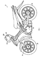
- FIG. 1 is a left side view of a motorcycle according to an embodiment of the present invention;
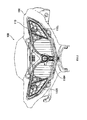
- FIG. 2 is a front view of a handlebar assembly including a headlight unit according to the embodiment of the present invention;
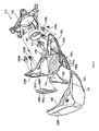
- FIG. 3 is an exploded perspective view of the headlight apparatus according to the embodiment of the present invention;
- FIG. 4 is a plan view of the headlight apparatus according to the embodiment of the present invention; and
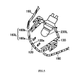
- FIG. 5 is a cross-sectional view taken along line F5-F5 of FIG. 4.
- An embodiment of a vehicle according to the present invention will now be described with reference to the drawings. In the following descriptions in regard to the drawings, identical or similar parts are denoted by the identical or similar reference numerals. It should be noted that each drawing is a schematic diagram, and may represent different dimensional ratios and the like from those of the actual apparatus. Hence, specific dimensions and the like should be determined in consideration of the following descriptions. Furthermore, as a matter of course, different drawings include elements which have different dimensional relations and ratios.
- FIG. 1 is a left side view of a
motorcycle 10, which is a vehicle according to this embodiment. As shown in FIG. 1, themotorcycle 10 is a so-called underbone-type motorcycle having a body frame (not shown) disposed at a lower position as compared with that of a general straddle-type motorcycle. - The
motorcycle 10 has afront wheel 20 and arear wheel 70, and drives therear wheel 70 with a driving force generated by anengine 50. - The
motorcycle 10 has a pair of left andright front forks 21 that rotatably support thefront wheel 20. Specifically, thefront forks 21 move (in a linear motion) thefront wheel 20 vertically (in practice, in the direction along which a predetermined caster angle is provided) in accordance with a change in a road condition, to thereby absorb shocks received on thefront wheel 20. - A
handlebar assembly 100 is disposed above thefront forks 21. Thehandlebar assembly 100 includes ahandlebar 40 to be manipulated by a rider to steer thefront wheel 20, and aheadlight unit 110. - The configuration of the
headlight unit 110 that forms the headlight apparatus in this embodiment will now be described. - FIG. 2 is a front view of the
handlebar assembly 100 including theheadlight unit 110. FIG. 3 is an exploded perspective view of theheadlight unit 110. - As shown in FIG. 2, the
handlebar assembly 100 has theheadlight unit 110 and ahandlebar cover 190 that surrounds theheadlight unit 110. - The
headlight unit 110 includes aheadlight section 110H and left andright flasher sections flasher sections flasher sections headlight section 110H. - The
headlight unit 110 has a headlight lens 121 (not shown in FIG. 2; see FIG. 3). Theflasher sections respective flasher lenses 122L, 122R (not shown in FIG. 2; see FIG. 3). - As shown in FIG. 3, the
headlight unit 110 has afront lens 120, aheadlight body 130, and aheadlight bracket 140. - The
front lens 120 is made of a transparent synthetic resin and is formed with theheadlight lens 121 andflasher lenses 122L, 122R. Specifically, theheadlight lens 121 and theflasher lenses 122L, 122R are formed in one unit. - The
headlight lens 121 is disposed forward of aheadlight bulb 210. Eachflasher lens 122L, 122R is disposed forward of arespective flasher bulb flasher lens 122L, 122R in this embodiment forms a directional indicator lens. Eachflasher bulb - The
headlight body 130 includes aheadlight reflector 131, left and rightposition lamp reflectors right flasher reflectors - The
headlight reflector 131 reflects light emitted from theheadlight bulb 210 attached to thereflector 131. - Each
position lamp reflector respective position lamp - The
position lamps motorcycle 10. The luminous energy of theposition lamps headlight bulb 210. Thereflectors position lamps reflector 131 and theheadlight bulb 210. - Each
flasher reflector respective flasher bulb - When a traveling direction change is intended, one of the
flasher bulbs motorcycle 10; specifically, one of right and left directions. Theflasher bulbs respective reflector position lamp reflectors flasher reflectors flasher bulbs position reflectors 132Lposition lamps - The
headlight bracket 140 supports thefront lens 120 and theheadlight body 130 and permits these supported components to be moved vertically; that is, to be capable of adjusted for aiming. In addition, theheadlight bracket 140 is fixed to thehandlebar cover 190. - A light-shielding
wall 150 is disposed between thefront lens 120 and theheadlight body 130. Alouver 160L is disposed to the left side of the light-shieldingwall 150. Alouver 160R is disposed to the right side of the light-shieldingwall 150. - The light-shielding
wall 150 shields light emitted from theheadlight bulb 210 and light reflected from thereflector 131. The light-shieldingwall 150 is disposed between thefront lens 120 and thereflector 131. The light-shieldingwall 150 is disposed between thefront lens 120 and theheadlight bulb 210. - The
louvers respective flasher lenses 122L, 122R. Thelouvers louver flasher bulbs - The
louvers plate portions 160a each having the geometry of a substantially flat plate. Specifically, eachlouver plate portions 160a. Thelouvers outer frame portion 160b that supports the twoplate portions 160a. - In this embodiment, the
plate portions 160a are disposed along the longitudinal direction of theheadlight unit 110; that is, along the widthwise direction of the vehicle. - The
louvers front lens 120 and theheadlight body 130. Specifically, eachlouver respective flasher lens 122L, 122R andrespective reflectors louver inner surface 120a (not shown in FIG. 3; see FIG. 5) of arespective flasher lens 122L, 122R. - A
socket cover 240 that covers a base (not shown) of theheadlight bulb 210 is attached to the rear of theheadlight body 130. - Next, referring to FIGs. 4 and 5, arrangement of the
louvers flasher bulbs - As shown in FIG. 4, an optical axis A1 of the
left flasher bulb 230L is oriented to extend obliquely forwardly from themotorcycle 10 while theheadlight unit 110 is attached to themotorcycle 10. Theright flasher bulb 230R is disposed in substantially symmetrical relation to theleft flasher bulb 230L. - Specifically, the optical axis A1 extends to obliquely intersect the Front-Rear (F-R) direction in FIG.4. In other words, the optical axis A1 is outwardly oriented as compared with the fore-and-aft direction of the
motorcycle 10. - FIG. 5 is a cross-sectional view taken along line F5-F5 of FIG. 4. As shown in FIG. 5, the left positioned
louver 160L is disposed inside thefront lens 120; specifically, inside theleft flasher lens 122L. More specifically, theleft louver 160L is disposed on theinner surface 120a of theleft flasher lens 122L. - The
left flasher bulb 230L attached to the headlight body 130 (specifically, theleft flasher reflector 133L) is located to the rear of thelouver 160L. Thehandlebar cover 190 covers thefront lens 120 from above and below thefront lens 120. - In the
headlight unit 110, thelouvers respective flasher lenses 122L, 122R are disposed on theinner surface 120a of theflasher lenses 122L, 122R. Hence, eachlouver respective flasher bulbs - In other words, the
headlight unit 110 attains adjustment of the luminous energy and the traveling direction of the light emitted from theflasher bulbs flasher lenses 122L, 122R. - Since the
louvers inner surface 120a ofrespective flasher lenses 122L, 122R, thelouvers flasher bulbs louvers flasher lenses 122L, 122R. - Hence, adjustment of the luminous energy and the traveling direction of the light emitted from the
flasher bulbs headlight unit 110; specifically, theflasher sections louvers flasher bulbs flasher bulbs louvers - Furthermore, since the
louvers inner surface 120a of theflasher lenses 122L, 122R, thelouvers louvers flasher lenses 122L, 122R. Improvement of thelouvers - In this embodiment, the
headlight lens 121 and theflasher lenses 122L, 122R are formed integrally. Hence, theheadlight unit 110 that includes theheadlight section 110H and theflasher sections - In this embodiment, the
louvers plate portions 160a. Hence, adjustment of the luminous energy and the traveling direction of the light emitted from theflasher bulbs - In addition, the
louvers outer frame portion 160b that supports the plurality ofplate portions 160a. Hence, attachment of thelouvers plate portions 160a to theheadlight body 130 is facilitated. - In this embodiment, the optical axis A1 of the
flasher bulbs motorcycle 10 while theheadlight unit 110 is attached to themotorcycle 10. This causes flashing of theflasher bulbs motorcycle 10 without fail. - Heretofore, while the invention has been described based on the embodiment shown in the drawings, it should be understood that the description and the drawings forming a part of this disclosure do not limit the scope of this invention. Alternative embodiments based on the disclosure will be apparent to those skilled in the art.
- For example, in the aforementioned embodiment, the optical axis A1 of the
flasher bulbs motorcycle 10. However, the optical axis A1 of theflasher bulbs - In the aforementioned embodiment, the
louvers outer frame portion 160b. However, thelouvers outer frame portion 160b. - In the aforementioned embodiment, the
louvers plate portions 160a. However, the number of theplate portion 160a may be of other than two. In addition, theplate portion 160a may be of a rod shape (a round rod or an angular rod shape). Furthermore, in the aforementioned embodiment, theplate portions 160a are disposed along the widthwise direction of the motorcycle. However, theplate portions 160a may be disposed along the vertical direction of themotorcycle 10. Also, one or more of the flat plate portions may be adjustable. This may allow the orientation of the light emitted to be adjusted. - Thus, as a matter of course, the invention includes various embodiments that are not described in this document. Hence, the technical scope of the present invention is defined only by particular matters of the invention as set forth in the appended claims reasonably understandable based on the description.
- It should be understood that while the present invention has been described as having left and right directional indicator arrangements which are identical, the headlight apparatus may not be limited as such and may include a single directional indicator, ar two different directional indicators.
-
- 10:
- motorcycle
- 20:
- front wheel
- 21:
- front fork
- 40:
- handlebar
- 50:
- engine
- 70:
- rear wheel
- 100:
- handlebar assembly
- 110:
- headlight unit (headlight apparatus)
- 110H:
- headlight section
- 110L, 110R:
- flasher section
- 120:
- front lens
- 120a:
- inner surface
- 121:
- headlight lens
- 122L, 122R:
- flasher lens
- 130:
- headlight body
- 131, 132L, 132R, 133L, 133R:
- reflector
- 140:
- headlight bracket
- 150:
- light-shielding wall
- 160L, 160R:
- louver
- 160a:
- plate portion
- 160b:
- outer frame portion
- 190:
- handlebar cover
- 210:
- headlight bulb
- 220L, 220R:
- position lamp
- 230L, 230R:
- flasher bulb
- 240:
- socket cover
- A1:
- optical axis
Claims (11)
- A headlight apparatus (110) comprising a directional indicator (110L, 110R) including:a light source (230L, 230R) adapted to flash;a directional indicator lens (122L, 122R) disposed forward of the light source (230L, 230R); anda partition (160L, 160R) for partitioning the directional indicator lens (122L, 122R), wherein the partition (160L, 160R) is disposed on an inner surface of the directional indicator lens (122L, 122R).
- The headlight apparatus (110) according to claim 1, further comprising a headlight (110H).
- The headlight apparatus (110) according to claim 1 or 2, wherein the light source (230L, 230R) is adapted to flash at a predetermined intervals.
- The headlight apparatus (110) according to claim 2 or 3, wherein the directional indicator (110L, 110R) is adjacent to the headlight (110H).
- The headlight apparatus (110) according to claim 2, 3 or 4, wherein the headlight (110H) has a headlight lens (121) and the directional indicator lens (122L, 122R) and the headlight lens (121) are formed in one unit.
- The headlight apparatus (110) according to any preceding claim, wherein the partition (160L, 160R) has a plate portion (160a) having a geometry of a substantially flat plate.
- The headlight apparatus (110) according to claim 5, wherein the partition (160L, 160R has a plurality of the plate portions (160a).
- The headlight apparatus (110) according to claim 6 or 7, wherein the partition (160L, 160R) further has an outer frame portion (160b) that supports the plate portion (160a).
- The headlight apparatus (110) according to any preceding claim, wherein an optical axis (A1) of the light source (230L, 230R) is oriented to extend obliquely forwardly from a vehicle (10) while the headlight apparatus (110) is attached to the vehicle (10).
- The headlight apparatus (110) of any preceding claim, comprising first and second directional indicators (110L, 110R) adapted to be positioned on respective right and left sides of a vehicle (10) in a vehicle width direction.
- A vehicle (10) comprising a headlight apparatus (110) according to any one of claims 1 to 10.
Applications Claiming Priority (1)
| Application Number | Priority Date | Filing Date | Title |
|---|---|---|---|
| JP2006269999A JP2008091179A (en) | 2006-09-29 | 2006-09-29 | Headlight device and vehicle |
Publications (2)
| Publication Number | Publication Date |
|---|---|
| EP1908630A2 true EP1908630A2 (en) | 2008-04-09 |
| EP1908630A3 EP1908630A3 (en) | 2009-07-15 |
Family
ID=38787633
Family Applications (1)
| Application Number | Title | Priority Date | Filing Date |
|---|---|---|---|
| EP07253679A Withdrawn EP1908630A3 (en) | 2006-09-29 | 2007-09-17 | Headlight apparatus and vehice |
Country Status (6)
| Country | Link |
|---|---|
| US (1) | US20080239737A1 (en) |
| EP (1) | EP1908630A3 (en) |
| JP (1) | JP2008091179A (en) |
| BR (1) | BRPI0701658A (en) |
| CO (1) | CO5900013A1 (en) |
| MX (1) | MX2007012027A (en) |
Cited By (4)
| Publication number | Priority date | Publication date | Assignee | Title |
|---|---|---|---|---|
| EP2138390A1 (en) * | 2008-06-27 | 2009-12-30 | Yamaha Hatsudoki Kabushiki Kaisha | Lamp and motorcycle |
| EP2343233A1 (en) * | 2009-11-26 | 2011-07-13 | Honda Motor Co., Ltd. | Front lighting apparatus structure for saddle-riding type vehicle |
| EP2532574A1 (en) * | 2011-06-10 | 2012-12-12 | Honda Motor Co., Ltd. | Front structure of straddle type vehicle |
| EP2708799A3 (en) * | 2012-09-13 | 2018-04-18 | Kawasaki Jukogyo Kabushiki Kaisha | Head lamp unit for vehicle |
Families Citing this family (8)
| Publication number | Priority date | Publication date | Assignee | Title |
|---|---|---|---|---|
| JP5362489B2 (en) * | 2009-08-31 | 2013-12-11 | 本田技研工業株式会社 | Motorcycle headlight device |
| JP5474732B2 (en) * | 2009-12-17 | 2014-04-16 | 本田技研工業株式会社 | Front structure of saddle-ride type vehicle |
| JP5557607B2 (en) * | 2010-06-10 | 2014-07-23 | 本田技研工業株式会社 | Lights and motorcycles |
| JP6078368B2 (en) * | 2013-02-14 | 2017-02-08 | 本田技研工業株式会社 | Saddle riding vehicle |
| JP6109614B2 (en) * | 2013-03-22 | 2017-04-05 | 本田技研工業株式会社 | Saddle-type vehicle lights |
| JP6104675B2 (en) | 2013-03-29 | 2017-03-29 | 本田技研工業株式会社 | Motorcycle headlight device |
| JP6190611B2 (en) * | 2013-03-29 | 2017-08-30 | 本田技研工業株式会社 | Motorcycle headlight device |
| JP6844955B2 (en) * | 2016-05-10 | 2021-03-17 | 川崎重工業株式会社 | Headlamp device for vehicles |
Citations (5)
| Publication number | Priority date | Publication date | Assignee | Title |
|---|---|---|---|---|
| DE864836C (en) * | 1950-06-01 | 1953-01-29 | Franz Zwick | Anti-glare body for motor vehicle headlights |
| US4383290A (en) * | 1977-09-29 | 1983-05-10 | Itt Industries Inc. | Signal lamp |
| US4807094A (en) * | 1987-12-21 | 1989-02-21 | General Motors Corporation | Headlamp assembly |
| TW253999B (en) * | 1993-06-30 | 1995-08-11 | Hitachi Cable | |
| EP1382487A2 (en) | 2002-07-15 | 2004-01-21 | Fuji Jukogyo Kabushiki Kaisha | Vehicle lamp |
Family Cites Families (7)
| Publication number | Priority date | Publication date | Assignee | Title |
|---|---|---|---|---|
| US1463024A (en) * | 1921-01-24 | 1923-07-24 | William B Steinhauer | Automobile headlight |
| DE2634522A1 (en) * | 1976-07-31 | 1978-02-02 | Rau Swf Autozubehoer | Vehicle signalling light assembly - has collimator with moulded horizontal louvre pattern inside lens |
| EP0074726B1 (en) * | 1981-08-29 | 1985-05-02 | Britax Vega Limited | Vehicle lamp assembly |
| JP2878111B2 (en) * | 1994-03-09 | 1999-04-05 | 株式会社小糸製作所 | Vehicle lighting |
| DE19824053A1 (en) * | 1998-05-29 | 1999-12-02 | Hella Kg Hueck & Co | Lighting device for vehicles |
| JP2003086010A (en) * | 2001-06-27 | 2003-03-20 | Ichikoh Ind Ltd | Vehicle lighting |
| JP4030804B2 (en) * | 2002-06-07 | 2008-01-09 | 株式会社小糸製作所 | Vehicle lamp |
-
2006
- 2006-09-29 JP JP2006269999A patent/JP2008091179A/en active Pending
-
2007
- 2007-05-23 BR BRPI0701658-1A patent/BRPI0701658A/en not_active IP Right Cessation
- 2007-09-17 EP EP07253679A patent/EP1908630A3/en not_active Withdrawn
- 2007-09-24 US US11/860,425 patent/US20080239737A1/en not_active Abandoned
- 2007-09-28 MX MX2007012027A patent/MX2007012027A/en not_active Application Discontinuation
- 2007-09-28 CO CO07101634A patent/CO5900013A1/en active IP Right Grant
Patent Citations (5)
| Publication number | Priority date | Publication date | Assignee | Title |
|---|---|---|---|---|
| DE864836C (en) * | 1950-06-01 | 1953-01-29 | Franz Zwick | Anti-glare body for motor vehicle headlights |
| US4383290A (en) * | 1977-09-29 | 1983-05-10 | Itt Industries Inc. | Signal lamp |
| US4807094A (en) * | 1987-12-21 | 1989-02-21 | General Motors Corporation | Headlamp assembly |
| TW253999B (en) * | 1993-06-30 | 1995-08-11 | Hitachi Cable | |
| EP1382487A2 (en) | 2002-07-15 | 2004-01-21 | Fuji Jukogyo Kabushiki Kaisha | Vehicle lamp |
Cited By (7)
| Publication number | Priority date | Publication date | Assignee | Title |
|---|---|---|---|---|
| EP2138390A1 (en) * | 2008-06-27 | 2009-12-30 | Yamaha Hatsudoki Kabushiki Kaisha | Lamp and motorcycle |
| CN101612963B (en) * | 2008-06-27 | 2014-03-26 | 雅马哈发动机株式会社 | Lamp and motorcycle |
| EP2343233A1 (en) * | 2009-11-26 | 2011-07-13 | Honda Motor Co., Ltd. | Front lighting apparatus structure for saddle-riding type vehicle |
| EP2532574A1 (en) * | 2011-06-10 | 2012-12-12 | Honda Motor Co., Ltd. | Front structure of straddle type vehicle |
| US20120314435A1 (en) * | 2011-06-10 | 2012-12-13 | Honda Motor Co., Ltd | Front structure of straddle type vehicle |
| US9346507B2 (en) * | 2011-06-10 | 2016-05-24 | Honda Motor Co., Ltd. | Front structure of straddle type vehicle |
| EP2708799A3 (en) * | 2012-09-13 | 2018-04-18 | Kawasaki Jukogyo Kabushiki Kaisha | Head lamp unit for vehicle |
Also Published As
| Publication number | Publication date |
|---|---|
| CO5900013A1 (en) | 2008-03-31 |
| US20080239737A1 (en) | 2008-10-02 |
| JP2008091179A (en) | 2008-04-17 |
| EP1908630A3 (en) | 2009-07-15 |
| BRPI0701658A (en) | 2008-05-27 |
| MX2007012027A (en) | 2009-02-12 |
Similar Documents
| Publication | Publication Date | Title |
|---|---|---|
| EP1908630A2 (en) | Headlight apparatus and vehice | |
| EP1908629B1 (en) | Headlight device and vehicle | |
| US8454075B2 (en) | Front portion structure of saddle-ride type vehicle | |
| US9963182B2 (en) | Headlight for two-wheeled motor vehicle | |
| EP2641779A2 (en) | Sub headlight unit and sub headlight system for use in vehicle that leans into turns, and vehicle that leans into turns | |
| JP6116935B2 (en) | Motorcycle headlamp device | |
| JP2014210444A (en) | Light unit for vehicle turning in lean position, and vehicle turning in lean position | |
| JP5301295B2 (en) | Vehicle taillight device | |
| JP6506962B2 (en) | Straddle type vehicle | |
| JP2001043708A (en) | Headlights for motorcycles | |
| CN102654264B (en) | Headlamp construction for vehicle | |
| JP2016005942A (en) | Saddle riding vehicle | |
| JP6057772B2 (en) | Light fixture | |
| US20230249771A1 (en) | Headlight device and leaning vehicle | |
| JP2009234479A (en) | Headlight device for motorcycle | |
| JP4762629B2 (en) | Motorcycle lamp unit | |
| JP3328611B2 (en) | Headlights for motorcycles | |
| JP5624200B2 (en) | Vehicle headlamp device | |
| EP2017167B1 (en) | Vehicle | |
| JP7531548B2 (en) | Cornering light structure for saddle-type vehicles | |
| EP4566926A1 (en) | Straddled vehicle position light | |
| JP7853516B2 (en) | Saddle-type vehicle | |
| EP3437967B1 (en) | Headlight device for saddle-type vehicle | |
| JP5578035B2 (en) | Motorcycle headlamp device | |
| JP2011146246A (en) | Light distribution switching seal of headlamp for automobile |
Legal Events
| Date | Code | Title | Description |
|---|---|---|---|
| PUAI | Public reference made under article 153(3) epc to a published international application that has entered the european phase |
Free format text: ORIGINAL CODE: 0009012 |
|
| 17P | Request for examination filed |
Effective date: 20070926 |
|
| AK | Designated contracting states |
Kind code of ref document: A2 Designated state(s): AT BE BG CH CY CZ DE DK EE ES FI FR GB GR HU IE IS IT LI LT LU LV MC MT NL PL PT RO SE SI SK TR |
|
| AX | Request for extension of the european patent |
Extension state: AL BA HR MK RS |
|
| PUAL | Search report despatched |
Free format text: ORIGINAL CODE: 0009013 |
|
| AK | Designated contracting states |
Kind code of ref document: A3 Designated state(s): AT BE BG CH CY CZ DE DK EE ES FI FR GB GR HU IE IS IT LI LT LU LV MC MT NL PL PT RO SE SI SK TR |
|
| AX | Request for extension of the european patent |
Extension state: AL BA HR MK RS |
|
| AKX | Designation fees paid |
Designated state(s): AT BE BG CH CY CZ DE DK EE ES FI FR GB GR HU IE IS IT LI LT LU LV MC MT NL PL PT RO SE SI SK TR |
|
| 17Q | First examination report despatched |
Effective date: 20100409 |
|
| GRAP | Despatch of communication of intention to grant a patent |
Free format text: ORIGINAL CODE: EPIDOSNIGR1 |
|
| RIN1 | Information on inventor provided before grant (corrected) |
Inventor name: AOKI, YASHUSHI C/O YAMAHA MOTOR ASIAN CENTER CO., |
|
| STAA | Information on the status of an ep patent application or granted ep patent |
Free format text: STATUS: THE APPLICATION IS DEEMED TO BE WITHDRAWN |
|
| 18D | Application deemed to be withdrawn |
Effective date: 20130619 |