EP1908554A1 - Grinding plate for vacuum fixation of grinding material - Google Patents
Grinding plate for vacuum fixation of grinding material Download PDFInfo
- Publication number
- EP1908554A1 EP1908554A1 EP07117626A EP07117626A EP1908554A1 EP 1908554 A1 EP1908554 A1 EP 1908554A1 EP 07117626 A EP07117626 A EP 07117626A EP 07117626 A EP07117626 A EP 07117626A EP 1908554 A1 EP1908554 A1 EP 1908554A1
- Authority
- EP
- European Patent Office
- Prior art keywords
- sanding pad
- sanding
- abrasive material
- abrasive
- grinding
- Prior art date
- Legal status (The legal status is an assumption and is not a legal conclusion. Google has not performed a legal analysis and makes no representation as to the accuracy of the status listed.)
- Granted
Links
Images

Classifications
-
- B—PERFORMING OPERATIONS; TRANSPORTING
- B24—GRINDING; POLISHING
- B24D—TOOLS FOR GRINDING, BUFFING OR SHARPENING
- B24D9/00—Wheels or drums supporting in exchangeable arrangement a layer of flexible abrasive material, e.g. sandpaper
- B24D9/08—Circular back-plates for carrying flexible material
- B24D9/10—Circular back-plates for carrying flexible material with suction means for securing the material
-
- B—PERFORMING OPERATIONS; TRANSPORTING
- B24—GRINDING; POLISHING
- B24D—TOOLS FOR GRINDING, BUFFING OR SHARPENING
- B24D13/00—Wheels having flexibly-acting working parts, e.g. buffing wheels; Mountings therefor
- B24D13/14—Wheels having flexibly-acting working parts, e.g. buffing wheels; Mountings therefor acting by the front face
- B24D13/147—Wheels having flexibly-acting working parts, e.g. buffing wheels; Mountings therefor acting by the front face comprising assemblies of felted or spongy material; comprising pads surrounded by a flexible material
-
- B—PERFORMING OPERATIONS; TRANSPORTING
- B24—GRINDING; POLISHING
- B24D—TOOLS FOR GRINDING, BUFFING OR SHARPENING
- B24D15/00—Hand tools or other devices for non-rotary grinding, polishing, or stropping
- B24D15/04—Hand tools or other devices for non-rotary grinding, polishing, or stropping resilient; with resiliently-mounted operative surface
Definitions
- the invention relates to a sanding pad for a grinding device, which has a receptacle, is attached to the abrasive material by suction, wherein in the sanding pad a channel for attachment of the abrasive material is arranged by vacuum perpendicular to the grinding plane, which is located in the central region of the sanding pad.
- a sanding pad which absorbs flexible abrasive material by suction.
- the flexible abrasive material is formed from abrasive grain coated backing material.
- the sanding pad consists of a Primasaugkanal, of which star-shaped horizontal Saugaugäle in the direction Branch off the outside of the sanding plate and open into a plurality of vertical suction channels evenly distributed in the sanding disk. This arrangement has some disadvantages. Only flexible abrasive material can be used.
- the sanding pad must be made of non-deformable material when machining the workpieces to maintain the vacuum.
- the solution shown is only suitable for rotary sander. There are several suction openings on the abrasive material side of the sanding pad necessary to fix the flexible abrasive material.
- a machining apparatus in which a sanding pad is provided with a receptacle to which sanding material is attached by suction.
- a channel for fixing the abrasive material is arranged by means of vacuum perpendicular to the grinding plane.
- the channel is located in the central area of the sanding plate.
- the invention has for its object to provide a vacuum attachment of abrasive material to a grinder, with which the processing of flat and uneven surfaces is possible, with a cost-effective, yet secure attachment is also possible for small abrasives.
- the grinding disc according to the invention has for attachment to a grinding machine via a receptacle, is attached to the abrasive material by suction.
- the sanding pad has a channel at the center of the surface, which is perpendicular to the sanding plane and which runs from the sanding material side to the opposite side of the sanding surface Sanding plate runs.
- the attachment of an abrasive material is achieved without manual action by a vacuum is applied to an opening of a vacuum channel, which is located on the side facing away from the abrasive material of the grinding disc, which produces a non-positive connection of the abrasive material with the sanding pad.
- the saving of fasteners on the back of the abrasive material results in a significant cost savings. By eliminating manual attachment of the abrasive material also reduces the set-up of the grinding machine.
- the vacuum can be generated with the aid of one or more hoses and running through the inside of the machine channels or hoses on the sanding pad, so that a mobility of the sanding pad assembly when used in eccentric, linear or orbital sanders is made possible.
- Any carrier material coated with abrasive grain can be used in the arrangement without additional coating of the backing material back.
- material for the sanding plate metals or plastics can be used.
- the execution of a sanding plate made of plastic allows due to the elastic deformability of the sanding pad an adaptation of the sanding pad to a workpiece.
- the device according to the invention makes it possible to securely fasten very thin and flexible abrasives with very small diameters of support plates.
- the central arrangement of the suction opening and the flexible design of abrasive and receiving plate not only flat surfaces, but also curved surfaces can be edited.
- the abrasive can be tilted on the part to be machined without the vacuum is interrupted.
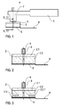
- FIG. 1 shows a rotary grinding machine.
- the grinding device 1 contains the sanding pad 2, a vacuum channel 4 extending through the drive shaft 3 and the sanding pad 2 and the abrasive material 5 fastened by vacuum.
- the sanding pad 2 is connected to the drive shaft 3 and via this to the drive unit 7.
- the abrasive material 5 is preferably designed as a round paper sheet with abrasive bodies mounted thereon. However, other forms are possible, for example, it may be formed as a wave edge.
- FIG. 2 shows an enlarged schematic sectional view of the grinding disk 2 contained in FIG. 1 along the section line A-A '.
- the abrasive material 5 is fixed by means of vacuum on the underside of the sanding pad 2.
- the threaded piece 6 connects the sanding pad 2 with the drive shaft 3 shown in Figure 1.
- the vacuum is preferably generated by means of ejectors, not shown here. It can also be produced with venturi nozzles, pumps, blowers and suckers.
- the vacuum is supplied to the grinder 1 via one or more hoses or through channels running inside the machine and directed via the vacuum channel 5 to the abrasive side of the sanding plate 2.
- the abrasive material 5 adheres by the suction effect on the sanding pad 2, wherein the sanding pad 2 consists of a material which ensures the highest possible static friction between sanding pad 2 and 5 abrasive material. As a result, a displacement of the abrasive material 5 is prevented on the sanding plate 2 and allows the safe processing of the workpieces.
- the sanding pad 2 consists of an upper part 2.1 and a lower part 2.2.
- Plastic or metal is preferably used for the upper part 2.1 consisting of a solid carrier material, while the lower part 2.2 consists of a flexible material, for example neoprene. It is also possible that the sanding pad 2 has on its underside, against which the abrasive 5, radial short slots which are connected to the central of the outlet opening of the vacuum channel and effect an improved contact of the abrasive 5.
- the use of elastic plastic material for the sanding pad 2 allows the machining of curved workpieces. It is particularly advantageous that the design according to the invention can also be used for small diameters and single-handed grinders.
- Figure 3 shows an embodiment in which in the lower part 2.2 of the grinding plate 2, a milled recess is 2.2.1 incorporated.
- the milled recess 2.2.1 is mounted as a circumferential groove on the lateral surface of the lower part 2.2.
- a stable disc 2.3 is attached at the bottom of the lower part 2.2, at which the abrasive 5 is sucked in.
- Figure 4 shows an embodiment for the design of a flexible abrasive material 5.
- the abrasive material 5 is designed as a round paper sheet with abrasive bodies mounted thereon.
- apertures are made around the center where the leaflet is sucked against the sanding pad 2.
- circular slits 5.1... 5.4 are stamped for this purpose. It is also possible that incisions or stampings of different shapes are appropriate. In addition to the better processing possibility of curved surfaces, this also results in improved adhesion of the paper to the sanding pad. 2
- FIG. 5 shows an arrangement in which the sanding pad 2 is mounted in an additional device 9.
- the attachment 9 is attached to a commercial hand grinder.
- the vacuum channel 4 is connected via a hose connection with a vacuum pump.
- the sanding pad 2 is driven by a belt drive 10 from the grinding wheel 11 of a hand grinder. This design allows for easy and inexpensive attachment of the pneumatic assembly to existing equipment.
Landscapes
- Engineering & Computer Science (AREA)
- Mechanical Engineering (AREA)
- Polishing Bodies And Polishing Tools (AREA)
Abstract
Die Erfindung betrifft einen Schleifteller für ein Schleifgerät, der eine Aufnahme aufweist, an der Schleifmaterial mittels Saugwirkung befestigt wird, wobei im Schleifteller ein Kanal zur Befestigung des Schleifmaterials mittels Vakuum senkrecht zur Schleifebene angeordnet ist, welcher sich im zentralen Bereich des Schleiftellers befindet. Der Erfindung liegt die Aufgabe zugrunde, eine Vakuumbefestigung von Schleifmaterial an einem Schleifgerät anzugeben, mit dem die Bearbeitung von ebenen und unebenen Flächen möglich ist, wobei eine kostengünstige und trotzdem sichere Befestigung auch für kleine Schleifmittel ermöglicht wird. Die Aufgabe wird erfindungsgemäß mit einer Anordnung gelöst, bei der das Schleifmaterial (5) aus einem flexiblen Schleifmaterial besteht, der Kanal (4) durch den Flächenmittelpunkt der Berührungsfläche des Schleiftellers (2) mit dem Schleifmittel (5) verläuft und der Schleifteller (2) aus einem starren Oberteil (2.1) und einem Unterteil (2.2) aus flexiblem Material besteht.The invention relates to a sanding pad for a grinding device, which has a receptacle, is attached to the abrasive material by suction, wherein in the sanding pad a channel for attachment of the abrasive material is arranged by vacuum perpendicular to the grinding plane, which is located in the central region of the sanding pad. The invention has for its object to provide a vacuum attachment of abrasive material to a grinder, with which the processing of flat and uneven surfaces is possible, with a cost-effective, yet secure attachment is also possible for small abrasives. The object is achieved with an arrangement in which the abrasive material (5) consists of a flexible abrasive material, the channel (4) through the center of area of the contact surface of the sanding pad (2) with the abrasive (5) and the sanding pad (2) consists of a rigid upper part (2.1) and a lower part (2.2) made of flexible material.
Description
Die Erfindung betrifft einen Schleifteller für ein Schleifgerät, der eine Aufnahme aufweist, an der Schleifmaterial mittels Saugwirkung befestigt wird, wobei im Schleifteller ein Kanal zur Befestigung des Schleifmaterials mittels Vakuum senkrecht zur Schleifebene angeordnet ist, welcher sich im zentralen Bereich des Schleiftellers befindet.The invention relates to a sanding pad for a grinding device, which has a receptacle, is attached to the abrasive material by suction, wherein in the sanding pad a channel for attachment of the abrasive material is arranged by vacuum perpendicular to the grinding plane, which is located in the central region of the sanding pad.
Im Stand der Technik sind verschiedene Befestigungsarten von Schleifpapier an einem Schleifteller bekannt. Aus
Aus
In
Aus
Der Erfindung liegt die Aufgabe zugrunde, eine Vakuumbefestigung von Schleifmaterial an einem Schleifgerät anzugeben, mit dem die Bearbeitung von ebenen und unebenen Flächen möglich ist, wobei eine kostengünstige und trotzdem sichere Befestigung auch für kleine Schleifmittel ermöglicht wird.The invention has for its object to provide a vacuum attachment of abrasive material to a grinder, with which the processing of flat and uneven surfaces is possible, with a cost-effective, yet secure attachment is also possible for small abrasives.
Die Aufgabe wird erfindungsgemäß mit einer Anordnung, welche die im Anspruch 1 angegebenen Merkmale aufweist, gelöst.The object is achieved with an arrangement having the features specified in
Vorteilhafte Weiterbildungen der Erfindung sind Gegenstand der Unteransprüche. Gegenstand der Anmeldung sind auch Merkmalskombinationen bei denen die in der Beschreibung und/oder in den Ansprüchen angegebenen Einzelmerkmale beliebig miteinander kombiniert werden.Advantageous developments of the invention are the subject of the dependent claims. The application also relates to combinations of features in which the individual features specified in the description and / or in the claims are combined with one another as desired.
Der erfindungsgemäße Schleifteller verfügt zur Anbringung an einer Schleifmaschine über eine Aufnahme, an der Schleifmaterial mittels Saugwirkung befestigt wird. Der Schleifteller weist im Flächenmittelpunkt einen Kanal auf, der senkrecht zur Schleifebene steht und der von der Schleifmaterialseite zur gegenüberliegenden Seite des Schleiftellers verläuft. Vorteilhaft bei dieser Anordnung ist, dass nur ein Vakuumkanal zur Erzeugung der Haftung notwendig ist.The grinding disc according to the invention has for attachment to a grinding machine via a receptacle, is attached to the abrasive material by suction. The sanding pad has a channel at the center of the surface, which is perpendicular to the sanding plane and which runs from the sanding material side to the opposite side of the sanding surface Sanding plate runs. An advantage of this arrangement is that only a vacuum channel for generating the adhesion is necessary.
Die Befestigung eines Schleifmaterials wird ohne manuelle Tätigkeit erreicht, indem an einer Öffnung eines Vakuumkanals, die sich an der dem Schleifmaterial abgewandten Seite des Schleiftellers befindet, ein Vakuum angelegt wird, welches eine kraftschlüssige Verbindung des Schleifmaterials mit dem Schleifteller herstellt. Durch die Einsparung von Befestigungsmitteln auf der Rückseite des Schleifmaterials ergibt sich eine erhebliche Kostenersparnis. Durch den Wegfall einer manuellen Befestigung des Schleifmaterials reduziert sich außerdem die Rüstzeit der Schleifmaschine.The attachment of an abrasive material is achieved without manual action by a vacuum is applied to an opening of a vacuum channel, which is located on the side facing away from the abrasive material of the grinding disc, which produces a non-positive connection of the abrasive material with the sanding pad. The saving of fasteners on the back of the abrasive material results in a significant cost savings. By eliminating manual attachment of the abrasive material also reduces the set-up of the grinding machine.
Das Vakuum kann mit Hilfe eines oder mehrerer Schläuche sowie durch im Inneren der Maschine verlaufende Kanäle oder Schläuche am Schleifteller erzeugt werden, so dass auch eine Beweglichkeit der Schleiftelleranordnung bei dem Einsatz in Exzenter-, Linear- oder Schwingschleifern ermöglicht wird.The vacuum can be generated with the aid of one or more hoses and running through the inside of the machine channels or hoses on the sanding pad, so that a mobility of the sanding pad assembly when used in eccentric, linear or orbital sanders is made possible.
Es ist jedes mit Schleifkorn beschichtetes Trägermaterial in der Anordnung ohne zusätzliche Beschichtung der Trägermaterialrückseite verwendbar. Als Material für den Schleifteller sind Metalle oder Kunststoffe verwendbar. Die Ausführung eines Schleiftellers aus Kunststoff ermöglicht aufgrund der elastischen Verformbarkeit des Schleiftellers eine Anpassung des Schleiftellers an ein Werkstück.Any carrier material coated with abrasive grain can be used in the arrangement without additional coating of the backing material back. As material for the sanding plate metals or plastics can be used. The execution of a sanding plate made of plastic allows due to the elastic deformability of the sanding pad an adaptation of the sanding pad to a workpiece.
Die erfindungsgemäße Vorrichtung ermöglicht es, sehr dünne und flexible Schleifmittel mit sehr kleinen Durchmessern von Trägertellern sicher zu befestigen. Durch die zentrale Anordnung der Ansaugöffnung und die flexible Ausführung von Schleifmittel und Aufnahmeteller können nicht nur plane Flächen, sondern auch gewölbte Flächen bearbeitet werden. Das Schleifmittel kann verkantet auf das zu bearbeitende Teil aufgesetzt werden, ohne dass das Vakuum unterbrochen wird.The device according to the invention makes it possible to securely fasten very thin and flexible abrasives with very small diameters of support plates. The central arrangement of the suction opening and the flexible design of abrasive and receiving plate not only flat surfaces, but also curved surfaces can be edited. The abrasive can be tilted on the part to be machined without the vacuum is interrupted.
Im Folgenden wird die Erfindung an einem Ausführungsbeispiel näher erläutert. In der zugehörigen Zeichnung zeigen:
Figur 1- eine schematische Darstellung einer Ausführungsform für eine Rotationsschleifmaschine,
Figur 2- eine Schnittdarstellung durch den Schleifteller entlang der Schnittlinie A - A',
Figur 3- eine Schnittdarstellung entlang der Schnittlinie A - A' durch einen Schleifteller mit Einfräsung im Trägermaterial,
Figur 4- eine spezielle Schleifmittelausführung
und Figur 5- eine Anordnung, bei der der Schleifteller in einer Zusatzeinrichtung an einer handelsüblichen Schleifmaschine angebracht ist
- FIG. 1
- a schematic representation of an embodiment for a rotary grinding machine,
- FIG. 2
- a sectional view through the sanding pad along the section line A - A ',
- FIG. 3
- a sectional view along the section line A - A 'through a grinding plate with milled in the substrate,
- FIG. 4
- a special abrasive version
and - FIG. 5
- an arrangement in which the sanding pad is mounted in an auxiliary device on a commercial grinding machine
In Figur 1 ist eine Rotationsschleifmaschine dargestellt. Das Schleifgerät 1 enthält den Schleifteller 2, einem durch die Antriebswelle 3 und den Schleifteller 2 verlaufenden Vakuumkanal 4 und das mittels Vakuum befestigte Schleifmaterial 5. Der Schleifteller 2 ist mit der Antriebswelle 3 und über diese mit der Antriebseinheit 7 verbunden. Das Schleifmaterial 5 ist vorzugsweise als rundes Blättchen aus Papier mit darauf befestigten Schleifkörpern ausgeführt. Es sind jedoch auch andere Formen möglich, z.B. kann es als Wellenrand ausgebildet sein. FIG. 1 shows a rotary grinding machine. The
Figur 2 zeigt eine vergrößerte schematische Schnittdarstellung des in Figur 1 enthaltenen Schleiftellers 2 entlang der Schnittlinie A-A'. Durch den Schleifteller 2 hindurch, senkrecht zur Schleifebene 8, verläuft der Vakuumkanal 4. Das Schleifmaterial 5 ist mittels Vakuum an der Unterseite des Schleiftellers 2 befestigt. Das Gewindestück 6 verbindet den Schleifteller 2 mit der in Figur 1 gezeigten Antriebswelle 3. Das Vakuum wird vorzugsweise mit Hilfe von hier nicht dargestellten Ejektoren erzeugt. Es kann aber auch mit Venturidüsen, Pumpen, Gebläse und Saugern erzeugt werden. Das Vakuum wird über ein oder mehrere Schläuche oder durch im Inneren der Maschine verlaufende Kanäle dem Schleifgerät 1 zugeführt und über den Vakuumkanal 5 zur Schleifmittelseite des Schleiftellers 2 geleitet. Durch das Vakuum wird bei am Schleifteller 2 anliegendem Schleifmaterial 5 eine Sogwirkung ausgebildet, die das Schleifmaterial 5 an den Schleifteller 2 saugt. Das Schleifmaterial 5 haftet durch die Sogwirkung am Schleifteller 2, wobei der Schleifteller 2 aus einem Material besteht, welches eine möglichst hohe Haftreibung zwischen Schleifteller 2 und Schleifmaterial 5 gewährleistet. Dadurch wird ein Verschieben des Schleifmaterials 5 auf dem Schleifteller 2 verhindert und die sichere Bearbeitung der Werkstücke ermöglicht. Der Schleifteller 2 besteht aus einem Oberteil 2.1 und einem Unterteil 2.2. Für das aus einem festen Trägermaterial bestehende Oberteil 2.1 wird vorzugsweise Kunststoff oder Metall verwendet, während das Unterteil 2.2 aus einem flexiblen Material, beispielsweise aus Neopren besteht. Es ist auch möglich, dass der Schleifteller 2 an seiner Unterseite, an der das Schleifmittel 5 anliegt, radiale kurze Schlitze aufweist, die mit der zentralen der Austrittsöffnung des Vakuumkanals verbunden sind und eine verbesserte Anlage des Schleifmittels 5 bewirken. Die Verwendung von elastischem Kunststoffmaterial für den Schleifteller 2 ermöglicht die Bearbeitung gekrümmter Werkstücke. Besonders vorteilhaft ist dabei, dass die erfindungsgemäße Ausführung auch für kleine Durchmesser und an Einhandschleifgeräten verwendbar ist. FIG. 2 shows an enlarged schematic sectional view of the
Figur 3 zeigt eine Ausführung, bei der in das Unterteil 2.2 des Schleiftellers 2 eine Einfräsung 2.2.1 eingearbeitet ist. Die Einfräsung 2.2.1 ist als umlaufende Nut an der Mantelfläche des Unterteils 2.2 angebracht. An der Unterseite des Unterteils 2.2, an der das Schleifmittel 5 angesaugt wird, ist eine stabile Scheibe 2.3 befestigt. Diese Gestaltung ermöglicht trotz fester/steifer Unterlage eine flexible Bearbeitung der Oberfläche, z.B. an Radien bzw. in Vertiefungen, bei gleichzeitiger stabiler Anlage am Schleifteller. Figure 3 shows an embodiment in which in the lower part 2.2 of the grinding
Figur 4 zeigt eine Ausführungsform für die Gestaltung eines flexiblen Schleifmaterials 5. Das Schleifmaterial 5 ist als rundes Blättchen aus Papier mit darauf befestigten Schleifkörpern ausgeführt. Um die zur Bearbeitung von gekrümmten Flächen erforderliche Flexibilität des Schleifmittels zu erhöhen, sind um das Zentrum, in dem das Blättchen an den Schleifteller 2 angesaugt wird, Durchbrüche angebracht. Im dargestellten Beispiel sind hierzu kreisförmig Schlitze 5.1 ... 5.4 eingestanzt. Es ist auch möglich, dass Einschnitte oder Einstanzungen verschiedener Formen angebracht sind. Neben der besseren Bearbeitungsmöglichkeit gekrümmter Flächen ergibt sich dadurch auch eine verbesserte Haftung des Papiers am Schleifteller 2. Figure 4 shows an embodiment for the design of a flexible
Aus Figur 5 ist eine Anordnung ersichtlich, bei der der Schleifteller 2 in einer Zusatzeinrichtung 9 angebracht ist. Die Zusatzeinrichtung 9 ist an einer handelsüblichen Handschleifmaschine befestigt. Der Vakuumkanal 4 ist über einen Schlauchanschluss mit einer Vakuumpumpe verbunden. Bei der dargestellten Ausführung wird der Schleifteller 2 über einen Riemenantrieb 10 von der Schleifscheibe 11 einer Handschleifmaschine angetrieben. Diese Ausführung ermöglicht ein einfaches und kostengünstiges Anbringen der pneumatischen Anordnung an vorhandene Geräte. FIG. 5 shows an arrangement in which the
- 11
- Schleifgerätsharpener
- 22
-
Schleifteller
2.1 Oberteil des Schleiftellers
2.2 Unterteil des Schleiftellers
2.2.1 Einfräsung
2.3 Scheibesanding pad
2.1 Upper part of the sanding plate
2.2 Lower part of the sanding plate
2.2.1 Milling
2.3 disc - 33
- Antriebswelledrive shaft
- 44
- Vakuumkanalvacuum channel
- 55
- Schleifmaterialabrasive material
- 66
- Gewindestückthreaded piece
- 77
- Antriebseinheitdrive unit
- 88th
- Schleifebenegrinding plane
- 99
- Zusatzeinrichtungaccessory
- 1010
- Riemenantriebbelt drive
- 1111
- Schleifscheibegrinding wheel
Claims (5)
Applications Claiming Priority (1)
| Application Number | Priority Date | Filing Date | Title |
|---|---|---|---|
| DE102006047007A DE102006047007A1 (en) | 2006-10-02 | 2006-10-02 | Disc grinder grinding plate, has channel for fixture of grinding material by vacuum normal to grinding plane |
Publications (2)
| Publication Number | Publication Date |
|---|---|
| EP1908554A1 true EP1908554A1 (en) | 2008-04-09 |
| EP1908554B1 EP1908554B1 (en) | 2009-04-22 |
Family
ID=38838948
Family Applications (1)
| Application Number | Title | Priority Date | Filing Date |
|---|---|---|---|
| EP07117626A Active EP1908554B1 (en) | 2006-10-02 | 2007-10-01 | Grinding plate for vacuum fixation of grinding material |
Country Status (4)
| Country | Link |
|---|---|
| EP (1) | EP1908554B1 (en) |
| AT (1) | ATE429308T1 (en) |
| DE (2) | DE102006047007A1 (en) |
| ES (1) | ES2326346T3 (en) |
Cited By (3)
| Publication number | Priority date | Publication date | Assignee | Title |
|---|---|---|---|---|
| IT201900005874A1 (en) * | 2019-04-16 | 2020-10-16 | Premier S R L | IMPROVED ABRASIVE GROUP FOR CERAMIC AND / OR STONE MATERIALS |
| US20220274225A1 (en) * | 2019-07-17 | 2022-09-01 | Rud. Starcke Gmbh & Co. Kg | Grinding device |
| EP4405133A4 (en) * | 2021-09-21 | 2025-09-10 | Buff And Shine Mfg Inc | POLISHING PAD |
Citations (4)
| Publication number | Priority date | Publication date | Assignee | Title |
|---|---|---|---|---|
| DD225093A1 (en) * | 1984-07-02 | 1985-07-24 | Sachsenring Automobilwerke | GRINDING PLATE FOR RECEIVING FLEXIBLE GRINDING BLADES BY MEANS OF SUCTION |
| EP0319729A2 (en) * | 1987-12-11 | 1989-06-14 | Gerd Braasch | Sanding device for treating surfaces, especially wooden surfaces |
| DE29809710U1 (en) * | 1998-05-29 | 1998-09-03 | Müller, Heinrich, 57635 Wölmersen | Machine processing device |
| WO1999067057A1 (en) * | 1998-06-23 | 1999-12-29 | Ekamant Ab | Pneumatic hand grinding tool |
Family Cites Families (1)
| Publication number | Priority date | Publication date | Assignee | Title |
|---|---|---|---|---|
| US1765808A (en) * | 1926-02-23 | 1930-06-24 | Carborundum Co | Surfacing apparatus |
-
2006
- 2006-10-02 DE DE102006047007A patent/DE102006047007A1/en not_active Withdrawn
-
2007
- 2007-10-01 EP EP07117626A patent/EP1908554B1/en active Active
- 2007-10-01 AT AT07117626T patent/ATE429308T1/en active
- 2007-10-01 DE DE502007000638T patent/DE502007000638D1/en active Active
- 2007-10-01 ES ES07117626T patent/ES2326346T3/en active Active
Patent Citations (4)
| Publication number | Priority date | Publication date | Assignee | Title |
|---|---|---|---|---|
| DD225093A1 (en) * | 1984-07-02 | 1985-07-24 | Sachsenring Automobilwerke | GRINDING PLATE FOR RECEIVING FLEXIBLE GRINDING BLADES BY MEANS OF SUCTION |
| EP0319729A2 (en) * | 1987-12-11 | 1989-06-14 | Gerd Braasch | Sanding device for treating surfaces, especially wooden surfaces |
| DE29809710U1 (en) * | 1998-05-29 | 1998-09-03 | Müller, Heinrich, 57635 Wölmersen | Machine processing device |
| WO1999067057A1 (en) * | 1998-06-23 | 1999-12-29 | Ekamant Ab | Pneumatic hand grinding tool |
Cited By (3)
| Publication number | Priority date | Publication date | Assignee | Title |
|---|---|---|---|---|
| IT201900005874A1 (en) * | 2019-04-16 | 2020-10-16 | Premier S R L | IMPROVED ABRASIVE GROUP FOR CERAMIC AND / OR STONE MATERIALS |
| US20220274225A1 (en) * | 2019-07-17 | 2022-09-01 | Rud. Starcke Gmbh & Co. Kg | Grinding device |
| EP4405133A4 (en) * | 2021-09-21 | 2025-09-10 | Buff And Shine Mfg Inc | POLISHING PAD |
Also Published As
| Publication number | Publication date |
|---|---|
| DE102006047007A1 (en) | 2008-04-03 |
| ATE429308T1 (en) | 2009-05-15 |
| DE502007000638D1 (en) | 2009-06-04 |
| EP1908554B1 (en) | 2009-04-22 |
| ES2326346T3 (en) | 2009-10-07 |
Similar Documents
| Publication | Publication Date | Title |
|---|---|---|
| EP1318892B1 (en) | Abrasive body and abrasive means for an electric grinding tool and electric grinding tool | |
| EP2125289B1 (en) | Tool set for an eccentric grinding machine | |
| DE69130864T2 (en) | GRINDING MACHINE WITH SWINGING PLATE AND ABRASIVE | |
| DE20023967U1 (en) | Electric hand grinder, in particular eccentric grinder | |
| DE19845166B4 (en) | Rotary tool in the embodiment of a ring disc for surface processing | |
| EP1910024B2 (en) | Device for machining a strip or plate-shaped metal workpiece | |
| DE2604233A1 (en) | SANDING OR POLISHING MACHINE WITH SUCTION | |
| EP2585253A1 (en) | Grinding tool for the simultaneous sanding and polishing of floors | |
| WO2012028505A1 (en) | Grinding wheel unit for a rotary grinding machine | |
| DE102017122141A1 (en) | Device for producing an undefined finishes on a surface of a metal workpiece in a continuous process | |
| EP1120198A2 (en) | Grinding tool, machine using the same and method using this tool for machining workpieces | |
| EP1908554B1 (en) | Grinding plate for vacuum fixation of grinding material | |
| EP2086720B1 (en) | Electric hand-held machine tool for carrying out grinding work, in particular an orbital sander | |
| EP0413956B1 (en) | Hand tool with grinding disc | |
| WO2002098607A1 (en) | Electric portable grinding machine, particularly an eccentric grinder, provided with edge protection | |
| DE3920021C1 (en) | ||
| AT507504B1 (en) | ADJUSTABLE BELT GRINDING TOOL | |
| DE10357143A1 (en) | Grinding assembly for an electric hand tool machine | |
| DE69007467T2 (en) | Double-sided grinding wheel with internal reinforcement. | |
| DE4302953C1 (en) | Oscillating grinding machine with shoe - has grinding shoe formed so that its locating surface carrying grinding medium is inclined to a plane at a reduced angle, which the rotation axis of the eccentric intersects at right angles | |
| CH696391A5 (en) | Grinding blade for hand-held linear or oscillating grinding machine, has concentrically arranged, circular, central grinding blade area comprising central exhaust opening, where blade is attached to plate body of grinding machine | |
| AT508063B1 (en) | GRINDING TOOL CARRIER WITH ESSENTIALLY CIRCULAR FLAT PLATES THAT HAVE BEEN MOUNTED ON A GRINDING PLATE | |
| EP0138112A2 (en) | Securing device for a portable belt sander | |
| DE19534014A1 (en) | Surface grinder using abrasive paper, with support and fixture for abrasive paper | |
| DE9419992U1 (en) | Adapter for connecting changeable tools to a working device |
Legal Events
| Date | Code | Title | Description |
|---|---|---|---|
| PUAI | Public reference made under article 153(3) epc to a published international application that has entered the european phase |
Free format text: ORIGINAL CODE: 0009012 |
|
| AK | Designated contracting states |
Kind code of ref document: A1 Designated state(s): AT BE BG CH CY CZ DE DK EE ES FI FR GB GR HU IE IS IT LI LT LU LV MC MT NL PL PT RO SE SI SK TR |
|
| AX | Request for extension of the european patent |
Extension state: AL BA HR MK RS |
|
| 17P | Request for examination filed |
Effective date: 20080314 |
|
| AKX | Designation fees paid |
Designated state(s): AT BE BG CH CY CZ DE DK EE ES FI FR GB GR HU IE IS IT LI LT LU LV MC MT NL PL PT RO SE SI SK TR |
|
| GRAP | Despatch of communication of intention to grant a patent |
Free format text: ORIGINAL CODE: EPIDOSNIGR1 |
|
| GRAS | Grant fee paid |
Free format text: ORIGINAL CODE: EPIDOSNIGR3 |
|
| GRAA | (expected) grant |
Free format text: ORIGINAL CODE: 0009210 |
|
| AK | Designated contracting states |
Kind code of ref document: B1 Designated state(s): AT BE BG CH CY CZ DE DK EE ES FI FR GB GR HU IE IS IT LI LT LU LV MC MT NL PL PT RO SE SI SK TR |
|
| REG | Reference to a national code |
Ref country code: GB Ref legal event code: FG4D Free format text: NOT ENGLISH |
|
| REG | Reference to a national code |
Ref country code: CH Ref legal event code: EP |
|
| REG | Reference to a national code |
Ref country code: IE Ref legal event code: FG4D |
|
| RIN2 | Information on inventor provided after grant (corrected) |
Inventor name: MESSERSCHMIDT, KLAUS Inventor name: NEEB, THOMAS |
|
| REF | Corresponds to: |
Ref document number: 502007000638 Country of ref document: DE Date of ref document: 20090604 Kind code of ref document: P |
|
| NLV1 | Nl: lapsed or annulled due to failure to fulfill the requirements of art. 29p and 29m of the patents act | ||
| REG | Reference to a national code |
Ref country code: ES Ref legal event code: FG2A Ref document number: 2326346 Country of ref document: ES Kind code of ref document: T3 |
|
| PG25 | Lapsed in a contracting state [announced via postgrant information from national office to epo] |
Ref country code: PT Free format text: LAPSE BECAUSE OF FAILURE TO SUBMIT A TRANSLATION OF THE DESCRIPTION OR TO PAY THE FEE WITHIN THE PRESCRIBED TIME-LIMIT Effective date: 20090822 Ref country code: FI Free format text: LAPSE BECAUSE OF FAILURE TO SUBMIT A TRANSLATION OF THE DESCRIPTION OR TO PAY THE FEE WITHIN THE PRESCRIBED TIME-LIMIT Effective date: 20090422 Ref country code: LT Free format text: LAPSE BECAUSE OF FAILURE TO SUBMIT A TRANSLATION OF THE DESCRIPTION OR TO PAY THE FEE WITHIN THE PRESCRIBED TIME-LIMIT Effective date: 20090422 |
|
| PG25 | Lapsed in a contracting state [announced via postgrant information from national office to epo] |
Ref country code: PL Free format text: LAPSE BECAUSE OF FAILURE TO SUBMIT A TRANSLATION OF THE DESCRIPTION OR TO PAY THE FEE WITHIN THE PRESCRIBED TIME-LIMIT Effective date: 20090422 Ref country code: NL Free format text: LAPSE BECAUSE OF FAILURE TO SUBMIT A TRANSLATION OF THE DESCRIPTION OR TO PAY THE FEE WITHIN THE PRESCRIBED TIME-LIMIT Effective date: 20090422 Ref country code: SE Free format text: LAPSE BECAUSE OF FAILURE TO SUBMIT A TRANSLATION OF THE DESCRIPTION OR TO PAY THE FEE WITHIN THE PRESCRIBED TIME-LIMIT Effective date: 20090722 Ref country code: IS Free format text: LAPSE BECAUSE OF FAILURE TO SUBMIT A TRANSLATION OF THE DESCRIPTION OR TO PAY THE FEE WITHIN THE PRESCRIBED TIME-LIMIT Effective date: 20090822 Ref country code: LV Free format text: LAPSE BECAUSE OF FAILURE TO SUBMIT A TRANSLATION OF THE DESCRIPTION OR TO PAY THE FEE WITHIN THE PRESCRIBED TIME-LIMIT Effective date: 20090422 Ref country code: SI Free format text: LAPSE BECAUSE OF FAILURE TO SUBMIT A TRANSLATION OF THE DESCRIPTION OR TO PAY THE FEE WITHIN THE PRESCRIBED TIME-LIMIT Effective date: 20090422 |
|
| REG | Reference to a national code |
Ref country code: IE Ref legal event code: FD4D |
|
| PG25 | Lapsed in a contracting state [announced via postgrant information from national office to epo] |
Ref country code: IE Free format text: LAPSE BECAUSE OF FAILURE TO SUBMIT A TRANSLATION OF THE DESCRIPTION OR TO PAY THE FEE WITHIN THE PRESCRIBED TIME-LIMIT Effective date: 20090422 Ref country code: EE Free format text: LAPSE BECAUSE OF FAILURE TO SUBMIT A TRANSLATION OF THE DESCRIPTION OR TO PAY THE FEE WITHIN THE PRESCRIBED TIME-LIMIT Effective date: 20090422 Ref country code: CZ Free format text: LAPSE BECAUSE OF FAILURE TO SUBMIT A TRANSLATION OF THE DESCRIPTION OR TO PAY THE FEE WITHIN THE PRESCRIBED TIME-LIMIT Effective date: 20090422 Ref country code: RO Free format text: LAPSE BECAUSE OF FAILURE TO SUBMIT A TRANSLATION OF THE DESCRIPTION OR TO PAY THE FEE WITHIN THE PRESCRIBED TIME-LIMIT Effective date: 20090422 Ref country code: DK Free format text: LAPSE BECAUSE OF FAILURE TO SUBMIT A TRANSLATION OF THE DESCRIPTION OR TO PAY THE FEE WITHIN THE PRESCRIBED TIME-LIMIT Effective date: 20090422 |
|
| PLBE | No opposition filed within time limit |
Free format text: ORIGINAL CODE: 0009261 |
|
| STAA | Information on the status of an ep patent application or granted ep patent |
Free format text: STATUS: NO OPPOSITION FILED WITHIN TIME LIMIT |
|
| 26N | No opposition filed |
Effective date: 20100125 |
|
| PG25 | Lapsed in a contracting state [announced via postgrant information from national office to epo] |
Ref country code: BG Free format text: LAPSE BECAUSE OF FAILURE TO SUBMIT A TRANSLATION OF THE DESCRIPTION OR TO PAY THE FEE WITHIN THE PRESCRIBED TIME-LIMIT Effective date: 20090722 |
|
| BERE | Be: lapsed |
Owner name: ONSYSTEM OHG Effective date: 20091031 |
|
| PG25 | Lapsed in a contracting state [announced via postgrant information from national office to epo] |
Ref country code: MC Free format text: LAPSE BECAUSE OF NON-PAYMENT OF DUE FEES Effective date: 20091031 |
|
| PG25 | Lapsed in a contracting state [announced via postgrant information from national office to epo] |
Ref country code: GR Free format text: LAPSE BECAUSE OF FAILURE TO SUBMIT A TRANSLATION OF THE DESCRIPTION OR TO PAY THE FEE WITHIN THE PRESCRIBED TIME-LIMIT Effective date: 20090723 Ref country code: BE Free format text: LAPSE BECAUSE OF NON-PAYMENT OF DUE FEES Effective date: 20091031 |
|
| PG25 | Lapsed in a contracting state [announced via postgrant information from national office to epo] |
Ref country code: IT Free format text: LAPSE BECAUSE OF FAILURE TO SUBMIT A TRANSLATION OF THE DESCRIPTION OR TO PAY THE FEE WITHIN THE PRESCRIBED TIME-LIMIT Effective date: 20090422 |
|
| PG25 | Lapsed in a contracting state [announced via postgrant information from national office to epo] |
Ref country code: MT Free format text: LAPSE BECAUSE OF FAILURE TO SUBMIT A TRANSLATION OF THE DESCRIPTION OR TO PAY THE FEE WITHIN THE PRESCRIBED TIME-LIMIT Effective date: 20090422 Ref country code: LU Free format text: LAPSE BECAUSE OF NON-PAYMENT OF DUE FEES Effective date: 20091001 |
|
| PG25 | Lapsed in a contracting state [announced via postgrant information from national office to epo] |
Ref country code: HU Free format text: LAPSE BECAUSE OF FAILURE TO SUBMIT A TRANSLATION OF THE DESCRIPTION OR TO PAY THE FEE WITHIN THE PRESCRIBED TIME-LIMIT Effective date: 20091023 |
|
| PG25 | Lapsed in a contracting state [announced via postgrant information from national office to epo] |
Ref country code: TR Free format text: LAPSE BECAUSE OF FAILURE TO SUBMIT A TRANSLATION OF THE DESCRIPTION OR TO PAY THE FEE WITHIN THE PRESCRIBED TIME-LIMIT Effective date: 20090422 |
|
| PG25 | Lapsed in a contracting state [announced via postgrant information from national office to epo] |
Ref country code: CY Free format text: LAPSE BECAUSE OF FAILURE TO SUBMIT A TRANSLATION OF THE DESCRIPTION OR TO PAY THE FEE WITHIN THE PRESCRIBED TIME-LIMIT Effective date: 20090422 |
|
| REG | Reference to a national code |
Ref country code: CH Ref legal event code: PL |
|
| PG25 | Lapsed in a contracting state [announced via postgrant information from national office to epo] |
Ref country code: CH Free format text: LAPSE BECAUSE OF NON-PAYMENT OF DUE FEES Effective date: 20111031 Ref country code: LI Free format text: LAPSE BECAUSE OF NON-PAYMENT OF DUE FEES Effective date: 20111031 |
|
| PGFP | Annual fee paid to national office [announced via postgrant information from national office to epo] |
Ref country code: SK Payment date: 20120924 Year of fee payment: 6 |
|
| PGFP | Annual fee paid to national office [announced via postgrant information from national office to epo] |
Ref country code: FR Payment date: 20121113 Year of fee payment: 6 |
|
| PGFP | Annual fee paid to national office [announced via postgrant information from national office to epo] |
Ref country code: ES Payment date: 20121023 Year of fee payment: 6 Ref country code: GB Payment date: 20121023 Year of fee payment: 6 |
|
| PGFP | Annual fee paid to national office [announced via postgrant information from national office to epo] |
Ref country code: AT Payment date: 20121022 Year of fee payment: 6 |
|
| REG | Reference to a national code |
Ref country code: AT Ref legal event code: MM01 Ref document number: 429308 Country of ref document: AT Kind code of ref document: T Effective date: 20131001 |
|
| GBPC | Gb: european patent ceased through non-payment of renewal fee |
Effective date: 20131001 |
|
| REG | Reference to a national code |
Ref country code: SK Ref legal event code: MM4A Ref document number: E 5917 Country of ref document: SK Effective date: 20131001 |
|
| PG25 | Lapsed in a contracting state [announced via postgrant information from national office to epo] |
Ref country code: GB Free format text: LAPSE BECAUSE OF NON-PAYMENT OF DUE FEES Effective date: 20131001 |
|
| REG | Reference to a national code |
Ref country code: FR Ref legal event code: ST Effective date: 20140630 |
|
| PG25 | Lapsed in a contracting state [announced via postgrant information from national office to epo] |
Ref country code: AT Free format text: LAPSE BECAUSE OF NON-PAYMENT OF DUE FEES Effective date: 20131001 Ref country code: SK Free format text: LAPSE BECAUSE OF NON-PAYMENT OF DUE FEES Effective date: 20131001 Ref country code: FR Free format text: LAPSE BECAUSE OF NON-PAYMENT OF DUE FEES Effective date: 20131031 |
|
| REG | Reference to a national code |
Ref country code: ES Ref legal event code: FD2A Effective date: 20150701 |
|
| REG | Reference to a national code |
Ref country code: ES Ref legal event code: FD2A Effective date: 20150708 |
|
| PG25 | Lapsed in a contracting state [announced via postgrant information from national office to epo] |
Ref country code: ES Free format text: LAPSE BECAUSE OF NON-PAYMENT OF DUE FEES Effective date: 20131002 |
|
| REG | Reference to a national code |
Ref country code: DE Ref legal event code: R082 Ref document number: 502007000638 Country of ref document: DE Representative=s name: PATENT- UND RECHTSANWAELTE LOESENBECK, SPECHT,, DE Ref country code: DE Ref legal event code: R081 Ref document number: 502007000638 Country of ref document: DE Owner name: RUD. STARCKE GMBH & CO. KG, DE Free format text: FORMER OWNER: ONSYSTEM OHG, 68649 GROSS-ROHRHEIM, DE |
|
| PGFP | Annual fee paid to national office [announced via postgrant information from national office to epo] |
Ref country code: DE Payment date: 20250801 Year of fee payment: 19 |