EP1050377A2 - Rotating machine grinding tool - Google Patents
Rotating machine grinding tool Download PDFInfo
- Publication number
- EP1050377A2 EP1050377A2 EP00105792A EP00105792A EP1050377A2 EP 1050377 A2 EP1050377 A2 EP 1050377A2 EP 00105792 A EP00105792 A EP 00105792A EP 00105792 A EP00105792 A EP 00105792A EP 1050377 A2 EP1050377 A2 EP 1050377A2
- Authority
- EP
- European Patent Office
- Prior art keywords
- grinding tool
- carrier body
- abrasive
- tool according
- disc
- Prior art date
- Legal status (The legal status is an assumption and is not a legal conclusion. Google has not performed a legal analysis and makes no representation as to the accuracy of the status listed.)
- Granted
Links
Images


Classifications
-
- B—PERFORMING OPERATIONS; TRANSPORTING
- B24—GRINDING; POLISHING
- B24D—TOOLS FOR GRINDING, BUFFING OR SHARPENING
- B24D13/00—Wheels having flexibly-acting working parts, e.g. buffing wheels; Mountings therefor
- B24D13/14—Wheels having flexibly-acting working parts, e.g. buffing wheels; Mountings therefor acting by the front face
-
- B—PERFORMING OPERATIONS; TRANSPORTING
- B24—GRINDING; POLISHING
- B24B—MACHINES, DEVICES, OR PROCESSES FOR GRINDING OR POLISHING; DRESSING OR CONDITIONING OF ABRADING SURFACES; FEEDING OF GRINDING, POLISHING, OR LAPPING AGENTS
- B24B9/00—Machines or devices designed for grinding edges or bevels on work or for removing burrs; Accessories therefor
- B24B9/02—Machines or devices designed for grinding edges or bevels on work or for removing burrs; Accessories therefor characterised by a special design with respect to properties of materials specific to articles to be ground
- B24B9/18—Machines or devices designed for grinding edges or bevels on work or for removing burrs; Accessories therefor characterised by a special design with respect to properties of materials specific to articles to be ground of wood
-
- B—PERFORMING OPERATIONS; TRANSPORTING
- B24—GRINDING; POLISHING
- B24D—TOOLS FOR GRINDING, BUFFING OR SHARPENING
- B24D13/00—Wheels having flexibly-acting working parts, e.g. buffing wheels; Mountings therefor
- B24D13/02—Wheels having flexibly-acting working parts, e.g. buffing wheels; Mountings therefor acting by their periphery
-
- B—PERFORMING OPERATIONS; TRANSPORTING
- B24—GRINDING; POLISHING
- B24D—TOOLS FOR GRINDING, BUFFING OR SHARPENING
- B24D13/00—Wheels having flexibly-acting working parts, e.g. buffing wheels; Mountings therefor
- B24D13/20—Mountings for the wheels
-
- B—PERFORMING OPERATIONS; TRANSPORTING
- B24—GRINDING; POLISHING
- B24D—TOOLS FOR GRINDING, BUFFING OR SHARPENING
- B24D9/00—Wheels or drums supporting in exchangeable arrangement a layer of flexible abrasive material, e.g. sandpaper
- B24D9/04—Rigid drums for carrying flexible material
Definitions
- the invention relates to a rotationally drivable Machine grinding tool consisting of one Carrier body, which by means of connecting elements to a Machine drive can be used and the at least one can be brought into contact with a workpiece to be ground Has a work surface that is equipped with abrasives.
- Grinding disks are known. Their working surfaces are usually equipped with abrasive cloth which serves as an abrasive. All surfaces of a disc can be used as the working surface which, when the disc rotates, are moved around the center of rotation of the disc with sufficient peripheral speed for grinding of the grinding wheels at the highest, so that surface areas located there are mostly equipped with grinding lines and the so-called Work surfaces "there.
- the work surfaces can be used to grind profiles of the grinding tools according to the one to be ground Profile be contoured.
- the contoured work surface is stuck with abrasive cloth that is so thin that it can be nestled into the contours. Used up Grinding lines must be removed from the grinding tool regularly loosened and re-glued on abrasive cloth be replaced.
- Grinding tools are included for each profile appropriate contouring is required, with several prepared and contoured grinding tools are to be provided simultaneously to the grinding process same workpieces not with long set-up and Interrupt downtimes and therefore inexpensive to have to burden.
- the invention is based on the object to provide a rotationally drivable grinding tool, that can be used universally and economically for any grinding work on workpieces, in particular Workpieces with a profiled surface, such as turned workpieces, profile strips or the like.
- the carrier body is designed as a disc, the is so thin, e.g. 1 mm that they are transverse to Disc level can spring elastically and in Disc center an approach to the fasteners and that the abrasive is a flat structure with one side with abrasive cloth, sandpaper or the same abrasive layer coated elastic Upholstery layer is, which, in the manner of a surround the outer edge of the disc with which Padding layer is attached to the support body.
- the formation of the carrier body as a disc has the Advantage that the support body at transverse to the plane of the disc pressure forces during grinding can yield resiliently. This enables an advantageous one soft grinding. In addition, this property of soft grinding also further promoted in that Carrier body or the disc grinding lines attached which is a cushion layer on its underside having.
- this cushioning layer both the two, about disc surfaces radially to the center of rotation, at least in the area of the periphery of the disc, as well the outer edge or the outer edge of the plate-shaped, as a disk or plate present carrier body in the Surrounding type of surround can also in essential radially acting pressure forces from the Cushion layer are cushioned, so that even with the narrow radius of the wrapped around the edge or the edge Sanding relatively aggressive, but without Chatter marks and without excessive friction heat builds up, especially at the bottom narrower and deeper Profiling of the workpieces, soft grinding.
- the grinding tool is advantageously relatively flat, so it is suitable to narrow grooves and punctures, as they are especially with wood turning parts or Turned parts made of metal and copper materials occur grind.
- the grinding tool according to the invention can for Grinding work is used, for which so far Contoured grinding wheels were required so that now a universal grinding tool is present.
- the abrasive is a flat structure that means a section or part of a band, a plate, a sanding sheet or similar raw or Starting element that is a layer Abrasive cloth or sandpaper according to desired Has grit on one side, the non-abrasive Back, equipped with an elastic padding layer is.
- the cushion layer is advantageously a foam appropriate porosity and elasticity. Not to them abrasive surface of the back, for example one Sanding, the upholstery is laminated or is the cushion layer with the surface of the back firmly connected, for example in that the foam foamed directly on the back of the sanding line is.
- the cushion layer has a thickness of approximately 1 to 5 mm, preferably 2.5-3 mm. Thinner upholstery layers can be easily pushed through with high sanding pressure, i.e. they can pierce locally, which means that the advantages of soft sanding are lost. On the other hand, thicker cushion layers have the disadvantage that they stretch or stretch excessively due to centrifugal forces, which can lead to undesired changes in shape and, under certain circumstances, detachment from the carrier body. A thickness of the cushion layer of approximately 2.5 mm and an open-cell plastic foam with a compression hardness of 10 - 60 and a density of 17 - 40 kg per m 3 have proven effective.
- a grinding tool in which the carrier body is also designed as a disc that is so thin is that it can spring elastically across the plane of the disc and those in the disc center an approach for that Has fasteners on rotating parts of a machine drive are present and that with the An abrasive that can be combined with a carrier body is a Ring body made of elastic material in the area its periphery with abrasive cloth, sandpaper or the same abrasive layer is provided and the Carrier body is attached.
- Carrier body and ring body together form one unit usable as a grinding tool attached to a Machine drive is attachable.
- the disk serving as the carrier body is in both Solutions according to the invention advantageously as a disc ring trained because the inner hole of a disc ring as Approach for fasteners can serve.
- the Hole edge of the inner hole for example, corresponding Have material reinforcements or thickenings that to recordings for clamping elements Fasteners can be formed, with which the Grinding tool on or on one through the inner hole extending, or protruding into the inner hole Shaft, a hollow cylinder, a bushing or a pin of a machine drive can be tensioned.
- the approach of the carrier body is a short e.g. 7 mm long sleeve formed, the disc about a radially protruding from the sleeve about 10 mm wide Collar flange corresponds.
- Form sleeve with collar flange thus the carrier body, which is identified by means of the sleeve Approach a wave easily, quickly and easily Hollow cylinder, a socket, a pin or the like rotating part of a machine drive is stuck and because of the sleeve also centered sufficiently precisely is.
- the configuration of the carrier body is like this hit that the corresponding to the disc Collar flange, based on the length of the sleeve, sits off-center on the sleeve.
- the inner surface of the sleeve can be radially inward protruding drivers that are in corresponding grooves e.g. the as a hollow cylinder, socket or the like present connecting elements or directly in the shaft or a journal of the machine drive intervene and ensure that the Ensure grinding tool.
- the sleeve and collar flange are particularly advantageous as a one-piece plastic injection-molded part.
- the sleeve and collar flange have roughly the same wall thickness and can be manufactured inexpensively from plastic in large quantities using the injection molding process.
- Other materials for the carrier body for example sheet metal, are possible.
- the collar flange has been edged with the padded abrasive, there is a cheap grinding tool that can be used universally for many grinding jobs and can be easily replaced after the abrasive layer has worn out.
- Worn grinding tools of the type according to the invention do not require reprocessing, as is the case with profiled grinding tools, but can also be completely disposed of.
- the grinding tools according to the invention are thus so-called Disposable Parts ".
- the plastic used to form the carrier body is, with particular advantage, a glass fiber reinforced polyamide.
- the glass fiber reinforcement produces the necessary strength despite the thin-walled design of the carrier body, but allows the desired resilient properties of the collar flange itself, i.e. also the yielding of the entire disc with appropriate pressure on a workpiece to be ground.
- a polyamide has the additional advantage that this material can be dissolved with formic acid, so that dissolved areas can act like an applied adhesive. As a result, after wetting the surfaces of the collar flange with formic acid, the abrasive with its cushioning layer or the alternatively provided ring body can be connected to the carrier body without any problem and without additional use of special adhesives.
- the cushion layer is an open-cell foam with which the detached material of the carrier body can bond particularly intensively and firmly, since the detached material can penetrate into the pores of the foam and for anchoring on the other side ensures as soon as the solvent evaporates and the Adhesive "has dried.
- the one intended as an alternative abrasive Ring body consists of a plastic foam, preferably polyurethane foam of predetermined hardness.
- the abrasive can be attached simply be designed so that the abrasive is in shape a predetermined, for dimensioning the Carrier body or the ring body in each case matching Blank is present. Cuts can be prepared and provide around the carrier body or ring body to equip with it. From plates, tapes, strips or the same raw material of the abrasive can be manufacture the corresponding blanks without further ado. Conveniently, everyone is directly on the carrier body attachable cut a flat, essentially round Stamped part with wedge-shaped edge cuts or Notches.
- edge incisions or notches make it possible to cut the abrasive according to Art an edging wrinkle-free around the outer edge of the Washer or the collar flange or to the curved Lay the work surface of the ring body.
- a hole is arranged in the center of the blank, the Diameter about the same, but not less than that Outside diameter of the approach of the sleeve Carrier body is. The hole in the center of the blank thus hinders attachment of the grinding tool a shaft or a clamping pin of a machine drive Not.
- the outer diameter of the ring body is so dimensioned that its outer peripheral surface the outer edge of the collar flange of the support body around pre-determined dimension and that the carrier body area of the outer peripheral surface of the Ring body has the abrasive layer. Because the ring body consists of elastic plastic foam, it forms a for the grinding behavior advantageous cushion, the the outer dimensions of the carrier body are outstanding Regions of the ring body even more advantageous Way can give way to an increased grinding pressure, because such protruding or outstanding areas of the somewhat stiffer collar flange of the carrier body to be supported excessively.
- a region facing away from the carrier body can be a fillet or similar profile be, which in turn has the abrasive layer. Fillets with different radii and varying dimensions of the bevels allow inexpensive provision various, universally usable grinding tools.
- the grinding tools can be operated with machine drives easy and quick connection, as a machine drive one on a drive journal of a machine includes stretchable hollow cylinder, the outer diameter is equal to the inside diameter of the carrier body and on the at least one of a carrier body with a ring body existing grinding tool attachable and by means of a Fixing member is attachable.
- the hollow cylinder also called a bush has a length that allows various grinding tools on the hollow cylinder to line up.
- the mutual alignment and assignment the grinding tools can be taken so that Abrasive tool combinations are formed that the each workpiece to be ground, in particular profiled workpiece.
- With new grinding tools equipped hollow cylinders can be provided, so that a changeover in an advantageously short assembly time is possible. Business interruptions can be on Press minimum.
- Every clamp ring has at least one clamping screw so that it is in Any slide-on position can be fixed on the hollow cylinder is.
- Spacers can be a predetermined distance between two attached to a hollow cylinder Adjust grinding tools.
- Each hollow cylinder has in its peripheral surface at least one longitudinal groove, in each of which one of the Carrier of a carrier body one on the hollow cylinder inserted grinding tool engages positively.
- the Hollow cylinder forms a rotating part of the machine drive and takes the attached body with the abrasive on it.
- spacers in a longitudinal groove rod parts which can be inserted in a form-fitting manner.
- Each Rod part is one of a plastic profile rod cut piece with the desired length.
- In the longitudinal groove of the hollow cylinder can also Engage the clamping screw of a clamping ring.
- Spacers must be relative be dimensioned or dimensioned by what machining is done. For the user of the This means that it has a variety of grinding tools Spacers made with the highest accuracy or - wrestle must be ready, which may be right time consuming and tedious way to get together combine to get the desired distance between two grinding tools on a hollow cylinder adjust.
- the rod parts make it possible in advantageously, a piece of predetermined length cut that off in the longitudinal groove of the hollow cylinder is used. That turns out from the rod part cut piece as too long, it can be easiest Be cut shorter. This measure is everyone relevant craftsmen familiar.
- Fig. 1 shows a grinding tool in the Side view cut.
- the grinding tool is there from a carrier body 1, in the peripheral region thereof Abrasive 2 is arranged.
- the carrier body is made from a disc 3 that is so thin e.g. 1 mm that it can spring elastically across the disc plane. in the Disc center is as an approach for Fasteners an approximately 7 mm short sleeve 4, wherein disk 3 approximately radially from sleeve 4 protruding collar flange corresponds.
- the abrasive 2 is a flat structure, which in the manner of a border around the outer edge 5 the disc 3 is placed.
- the abrasive includes a Abrasive cloth 6, one on the back has elastic cushion layer 7.
- the upholstery layer can Be foam or plastic foam and has one Thickness of about 2.5 mm, which gives good molding properties of the abrasive can be achieved. With The outer radius of the abrasive can be advantageous keep the area of the outer edge 5 small.
- Fig. 2 shows the carrier body 1 in one Side view.
- the same components are the same Reference numerals as designated in Fig. 1.
- Fig. 2 leaves especially in connection with Fig. 1 recognize that the the corresponding flange 3 collar flange based on the Length of the sleeve 4 sits off-center on the sleeve.
- Fig. 1 illustrates the thickness of the abrasive larger than the smallest distance of the disc 3 corresponding collar flange from the end 8 of the sleeve (Fig. 2), so that the advantageous visible in Fig. 1
- the excess of the abrasive results in a full Use of the lower front work surface of the Grinding tool (Fig. 1) allows.
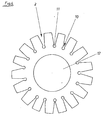
- FIG. 3 shows a top view of the carrier body 1 according to Fig. 2.
- the same components are the same Designated reference numbers.
- FIGS. 2 and 3 illustrate in particular the Formation of the carrier body 1 similar to a Disc ring, the inner surface of the sleeve facing radially internally projecting driver 9, which is the non-rotatable Attaching the carrier body to connecting elements or a shaft or spindle of a machine drive guarantee.
- Each carrier part is advantageously an injection molded part made of glass fiber reinforced polyamide, for example under the trade name Ultramid ".
- This is an impact-resistant and highly resilient plastic that enables the bending strength of the approximately 1 mm thin disc 3, which is in the form of a collar flange of the sleeve 4.
- This plastic also develops when dissolved with a suitable solvent, for example formic acid, Adhesive properties that can be used to advantage to connect the carrier body with abrasives.
- Fig. 4 shows in a plan view that the Abrasive in the form of a predetermined, for Dimensioning of the support body 3 each appropriate Blank is present.
- Abrasive 2 is a flat, in essential round stamped part with wedge-shaped Edge incisions 10, which are also called notches can be designated.
- the edge incisions 10 in Connection with those at the bottom of the incisions Holes 11 allow a wrinkle-free laying around Abrasive around the outer edge 5 of the form of a Disc 3 present carrier body 1.
- the ring-shaped area between the holes 11 and the inner hole 12 forms a main working side without any cuts. It also enables Inner hole 12 a concealed screw connection or Bracing with the drive machines.
- Fig. 5 shows schematically the preparation of the Grinding tool with connecting means to the shaft 13 of a machine drive.
- the connecting means include a clamping ring 14 seated on the shaft 13, which in Area of its outer circumference has grooves 15, in which the driver 9 of the carrier body 1 of the grinding tool can intervene to rotate the grinding tool to connect the shaft 13.
- the two clamping rings 14 and 16 are here in the manner of one Exploded view drawn. You can screwed or clamped together, which they Then clamp the grinding tool between them.
- Fig. 6 shows a second embodiment of the Connection of the grinding tool with a Machine drive.
- the clamping pin 18 has on the front side of its tenon 19, which can be inserted into the bore 17 is a threaded blind hole 20.
- the outside diameter of the Span lid 21 is approximately the same, but not greater than that Inner diameter of the sleeve of the carrier body 1. This can the stretch lid 21 on the shoulders 23 to the Bottom of the shortened compared to the sleeve length Driver 9 rest.
- the clamping cover 21 is thus in the sleeve sunk when he sunk with the Countersunk screw 24 attached to the pin base 19 of the pin 18 and as soon as all components are caught or Intermediate clamping of the grinding tool put together and have contracted.
- the clamping pin 18 can be placed in a chuck, for example an electric hand drill clamp.
- Fig. 7 shows another particularly advantageous Design option for connecting the grinding tool with a machine drive.
- the exemplary embodiment is a lower one in the clamping ring 14 ′′ Extension 25 of the inner bore 17 is provided in the one Usual spring ring 26 can be inserted.
- the clamping cover 21 also has an exemplary embodiment in FIG grooves 27 and 27 'cut into its circumference on the with the corresponding rotating position of the tension disc stand congruent to the drivers 9 of the carrier body 1, so that it can be pulled down without the Remove the tension cover 21. Likewise, at corresponding rotary position also a new one from below Grinding tool can be pushed on.
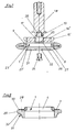
- FIG. 8 shows a side view of an alternative Embodiment of a grinding tool in section.
- the Carrier body is again designated 1 and consists of a sleeve 4 with disc 3, which is approximately radial from the collar flange protruding from the sleeve.
- Abrasive is here with the backing connected ring body 28 is provided.
- the ring body 28 consists of a polyurethane foam of predetermined hardness.
- the outer diameter of the ring body 1 is dimensioned that its outer peripheral surface 29 the outer edge 30 of the as a collar flange disc 3 around a pre-determined dimension.
- a to the carrier body 1 turned area 31 of the outer peripheral surface of the Ring body 28 has the abrasive layer 32, which here as dotted line is indicated. That of the carrier body turned area 31 of the outer peripheral surface of the Ring body 28 has a groove, so that appropriately profiled workpieces are ground can.
- FIG. 9 shows an embodiment of a grinding tool acc. Fig. 8, wherein the carrier body 1 with two Ring bodies 28 and 28 'is provided. This execution makes it possible to grind corresponding profiles or the grinding tool is easy to turn as soon as the Abrasive position of one of the ring bodies 28 or 28 'worn out is.
- FIG. 10 shows a ring body, the with Area 31 provided with abrasive layer 32 as a fillet is trained.
- Fig. 11 shows an annular body with a chamfer, the is provided with the abrasive layer 32.
- 12 is the Ring body 28 is not profiled and the periphery is one drawn over the upper edge of the ring body Abrasive layer 32 provided so that a shape is ready to grind a Palatinate.
- Fig. 13 is a longitudinal section of one on here Drive pin of a machine, not shown clamping hollow cylinder 34, part of a machine drive is.
- the outer diameter of the hollow cylinder 34 is the same as the inner diameter Carrier body 1.
- Both carrier bodies are again with fillets having annular bodies 28.
- a Copy ring 36 are set, so that here schematically indicated wooden profile 37 can be sanded.
- the upper carrier body 1 or that of the carrier body 1 and ring body 28 existing grinding tool can on the Hollow cylinder 34 attached with a locking member 38 be, the fixing body here as one on the Hollow cylinder 34 slide-on clamping ring 39 formed is by means of a clamping screw with hexagon socket 41 on the hollow cylinder in any longitudinal sliding position is fixable.
- the clamping ring is on this Embodiment in the direction of arrow 42 still postpone it until it's off the package Abrasive tools rests on the top Carrier body 1 of the first grinding tool strikes.
- FIG. 14 shows a schematic view of a Section of the outer surface of the hollow cylinder 34 with the Longitudinal groove 43.
- the arrow 45 shows like a piece a rod part 44 fits positively in the longitudinal groove.
- a machine drive is schematic Shown view, on the hollow cylinder 34 two Grinding tools are set in an arrangement like it corresponds to Fig. 13, with the grinding tools the ring body 28 visible here are illustrated.
- the Wood profile to be sanded is again designated 37 and the clamping ring with 39.
- Rod part 44 set as a spacer.
- the hollow cylinder so long that an additional cylindrical Grinding tool 46 can be plugged.
- the curves on the Outside edges of the wooden profile 37 can be sanded with the cylindrical surface 46 the straight surface 47 the outer edge of the wooden profile 37 are sanded.
- a new grinding process is carried out at which either the wooden profile 37 by at the Grinding machine existing facilities in a deeper Placed level and on the rotating machine drive is led past.
- the ring body 28 are excluded Function set and only the cylindrical Grinding tool 46 grinds.
- the management level of the wooden profile 37 in the Keep grinder and only the whole Machine drive, i.e. the spindle with the Grinding tools, offset in height to each either the ring body 28 or the abrasive layer on the circumference of the cylindrical grinding tool 46 for use bring.
Abstract
Description
Die Erfindung betrifft ein rotierend antreibbares Maschinen-Schleifwerkzeug, bestehend aus einem Trägerkörper, der mittels Verbindungselementen an einen Maschinen-Antrieb ansetzbar ist und der wenigstens eine mit einem zu schleifenden Werkstück in Anlage bringbare Arbeitsfläche hat, die mit Schleifmittel ausgerüstet ist.The invention relates to a rotationally drivable Machine grinding tool consisting of one Carrier body, which by means of connecting elements to a Machine drive can be used and the at least one can be brought into contact with a workpiece to be ground Has a work surface that is equipped with abrasives.
Schleifwerkzeuge der vorbeschriebenen Gattung sind
als sogenannte ![]()
![]()
Zum Schleifen von Profilen können die Arbeitsflächen der Schleifwerkzeuge entsprechend dem zu schleifenden Profil konturiert werden. Die konturierte Arbeitsfläche wird mit Schleifleinen beklebt, das so dünn ist, daß es in die Konturen einschmiegbar ist. Verbrauchtes Schleifleinen muß regelmäßig vom Schleifwerkzeug wieder gelöst und durch erneut aufgeklebtes Schleifleinen ersetzt werden.The work surfaces can be used to grind profiles of the grinding tools according to the one to be ground Profile be contoured. The contoured work surface is stuck with abrasive cloth that is so thin that it can be nestled into the contours. Used up Grinding lines must be removed from the grinding tool regularly loosened and re-glued on abrasive cloth be replaced.
Für jedes Profil werden Schleifwerkzeuge mit entsprechender Konturierung benötigt, wobei mehrere gleich konturierte Schleifwerkzeuge vorbereitet und gleichzeitig bereitzustellen sind, um den Schleifvorgang gleicher Werkstücke nicht mit langen Rüst- und Stillstandzeiten unterbrechen und somit kostenungünstig belasten zu müssen.Grinding tools are included for each profile appropriate contouring is required, with several prepared and contoured grinding tools are to be provided simultaneously to the grinding process same workpieces not with long set-up and Interrupt downtimes and therefore inexpensive to have to burden.
Das Schleifen mit derartigen Schleifwerkzeugen gestaltet sich folglich nur dann einigermaßen wirtschaftlich, wenn eine ausreichende Vielzahl gleicher Werkstücke zu schleifen ist, so daß sich die Bereithaltung von Sätzen entsprechend profilierter Schleifwerkzeuge lohnt.Grinding with such grinding tools is therefore only to some extent economical if a sufficient variety of the same Is to grind workpieces so that the Provision of sentences according to more profiled Grinding tools are worthwhile.
Die Vorteile des Schleifens von Werkstücken im industriellen Maßstab sind jedoch bei besonders individuell profilierten Werkstücken, zumal dann, wenn sie lediglich in geringen Stückzahlen anfallen, nicht mehr nutzbar. Dies gilt insbesondere für gedrechselte Holzteile, die zumeist nur in geringen Stückzahlen anfallen. Darüber hinaus haben gedrechselte Werkstücke oftmals derart feine oder auch tiefe Profilgebungen, daß der Grund entsprechend eingestochener Nuten, Pillen oder dergleichen, kaum oder nur sehr schwer mit einem an der Oberfläche eines konturierten Schleifwerkzeugs befindlichen Schleifleinen erreichbar ist. Um den Grund zu erreichen, wird oftmals der Schleifandruck erhöht, was jedoch wiederum in nachteiliger Weise entweder zum Abtragen an unerwünschter Stelle des Werkstücks führt oder zum Brennen des Schleifmittels aufgrund einer Andruck-Punktbelastung und der dann dort entstehenden erhöhten Reibungswärme.The advantages of grinding workpieces in industrial scale, however, are special at individually profiled workpieces, especially when they only occur in small quantities, not more usable. This applies particularly to turned items Wooden parts, mostly only in small numbers attack. They also have turned workpieces often such fine or deep profiles that the reason for appropriately pierced grooves, pills or the like, hardly or very difficult with one at the Surface of a contoured grinding tool abrasive lines located can be reached. For the reason to achieve, the grinding pressure is often increased, what however again disadvantageously either to Removal at an undesired point on the workpiece leads or to burn the abrasive due to a Pressure point load and the resulting pressure there increased frictional heat.
Der Erfindung liegt die Aufgabe zugrunde, ein rotierend antreibbares Schleifwerkzeug bereitzustellen, das universell und dabei wirtschaftlich einsetzbar ist für jegliche Schleifarbeiten an Werkstücken, insbesondere Werkstücken mit profilierter Oberfläche, wie zum Beispiel gedrechselten Werkstücken, Profilleisten oder dergleichen.The invention is based on the object to provide a rotationally drivable grinding tool, that can be used universally and economically for any grinding work on workpieces, in particular Workpieces with a profiled surface, such as turned workpieces, profile strips or the like.
Diese Aufgabe ist erfindungsgemäß dadurch gelöst, daß der Trägerkörper als Scheibe ausgebildet ist, die derart dünn ist, z.B. 1 mm, daß sie quer zur Scheibenebene elastisch federn kann und die im Scheibenzentrum einen Ansatz für die Verbindungselemente aufweist und daß das Schleifmittel ein flächiges Gebilde mit einer einseitig mit Schleifleinen, Schleifpapier oder dergleichen Abrasivlage beschichteten elastischen Polsterlage ist, welches, nach Art einer Einfassung um die Außenrandkante der Scheibe gelegt, mit der Polsterlage am Trägerkörper befestigt ist.According to the invention, this object is achieved by that the carrier body is designed as a disc, the is so thin, e.g. 1 mm that they are transverse to Disc level can spring elastically and in Disc center an approach to the fasteners and that the abrasive is a flat structure with one side with abrasive cloth, sandpaper or the same abrasive layer coated elastic Upholstery layer is, which, in the manner of a surround the outer edge of the disc with which Padding layer is attached to the support body.
Die Ausbildung des Trägerkörpers als Scheibe hat den Vorteil, daß der Trägerkörper bei quer zur Scheibenebene wirkenden Andruckkräften während der Schleifarbeiten federnd nachgeben kann. Dies ermöglicht ein vorteilhaftes weiches Schleifen. Zusätzlich wird diese Eigenschaft des weichen Schleifens auch dadurch weiter gefördert, daß am Trägerkörper bzw. der Scheibe Schleifleinen angebracht ist, welches an seiner Unterseite eine Polsterlage aufweist. Da diese Polsterlage sowohl die beiden, etwa radial zum Drehzentrum stehenden Scheibenflächen, zumindest im Bereich der Peripherie der Scheibe, als auch die Außenkante bzw. den Außenrand des plattenförmigen, als Scheibe bzw. Teller vorliegenden Trägerkörpers in der Art einer Einfassung umgibt, können ebenfalls im wesentlichen radial wirkende Andruckkräfte von der Polsterlage abgefedert werden, so daß sich auch mit dem engen Radius des um den Rand bzw. die Kante herumgelegten Schleifleinens relativ aggressiv, aber dennoch ohne Rattermarken und ohne daß sich übermäßige Reibungswärme aufbaut, insbesondere am Grund enger und tiefer Profilierungen der Werkstücke, weich schleifen läßt.The formation of the carrier body as a disc has the Advantage that the support body at transverse to the plane of the disc pressure forces during grinding can yield resiliently. This enables an advantageous one soft grinding. In addition, this property of soft grinding also further promoted in that Carrier body or the disc grinding lines attached which is a cushion layer on its underside having. Since this cushioning layer both the two, about disc surfaces radially to the center of rotation, at least in the area of the periphery of the disc, as well the outer edge or the outer edge of the plate-shaped, as a disk or plate present carrier body in the Surrounding type of surround can also in essential radially acting pressure forces from the Cushion layer are cushioned, so that even with the narrow radius of the wrapped around the edge or the edge Sanding relatively aggressive, but without Chatter marks and without excessive friction heat builds up, especially at the bottom narrower and deeper Profiling of the workpieces, soft grinding.
Das Schleifwerkzeug ist mit Vorteil relativ flach, so daß es geeignet ist, enge Rillen und Einstechungen, wie sie insbesondere bei Drechselteilen aus Holz oder Drehteilen aus Metall und Kupferstoffen vorkommen, zu schleifen.The grinding tool is advantageously relatively flat, so it is suitable to narrow grooves and punctures, as they are especially with wood turning parts or Turned parts made of metal and copper materials occur grind.
Das erfindungsgemäße Schleifwerkzeug kann für Schleifarbeiten benutzt werden, für welche bisher konturierte Schleifscheiben erforderlich waren, so daß nunmehr ein universell verwendbares Schleifwerkzeug vorliegt.The grinding tool according to the invention can for Grinding work is used, for which so far Contoured grinding wheels were required so that now a universal grinding tool is present.
Das Schleifmittel ist ein flächiges Gebilde, daß heißt, es kann ein Abschnitt bzw. ein Teil eines Bandes, einer Platte, eines Schleifblattes oder dergleichen Roh- bzw. Ausgangs-Element sein, das eine Lage aus Schleifleinen oder Schleifpapier entsprechend gewünschter Körnung hat, die an einer Seite, der nicht schleifenden Rückseite, mit einer elastischen Polsterlage ausgerüstet ist.The abrasive is a flat structure that means a section or part of a band, a plate, a sanding sheet or similar raw or Starting element that is a layer Abrasive cloth or sandpaper according to desired Has grit on one side, the non-abrasive Back, equipped with an elastic padding layer is.
Die Polsterlage ist mit Vorteil ein Schaumstoff mit entsprechender Porosität und Elastizität. Auf die nicht abrasive Fläche der Rückseite, beispielsweise eines Schleifleinens, ist die Polsterlage kaschiert bzw. ist die Polsterlage mit der Fläche der Rückseite fest verbunden, zum Beispiel dadurch, daß der Schaumstoff direkt auf die Rückseite des Schleifleinens geschäumt ist.The cushion layer is advantageously a foam appropriate porosity and elasticity. Not to them abrasive surface of the back, for example one Sanding, the upholstery is laminated or is the cushion layer with the surface of the back firmly connected, for example in that the foam foamed directly on the back of the sanding line is.
Die Polsterlage weist eine Dicke von etwa 1 bis 5 mm, vorzugsweise 2,5 - 3 mm auf. Dünnere Polsterlagen sind bei hohem Schleifandruck leicht durchdrückbar, das heißt sie können örtlich durchschlagen, wodurch die Vorteile des weichen Schleifens verloren gehen. Dickere Polsterlagen haben dagegen den Nachteil, daß sie sich aufgrund auftretender Fliehkräfte übermäßig recken bzw. dehnen, was zu unerwünschten Formänderungen und unter Umständen zum Ablösen vom Trägerkörper führen kann. Bewährt hat sich eine Dicke der Polsterlage von etwa 2,5 mm sowie ein offenzelliger Kunststoffschaum mit einer Stauch-Härte von 10 - 60 und einem Raumgewicht von 17 - 40 kg pro m3.The cushion layer has a thickness of approximately 1 to 5 mm, preferably 2.5-3 mm. Thinner upholstery layers can be easily pushed through with high sanding pressure, i.e. they can pierce locally, which means that the advantages of soft sanding are lost. On the other hand, thicker cushion layers have the disadvantage that they stretch or stretch excessively due to centrifugal forces, which can lead to undesired changes in shape and, under certain circumstances, detachment from the carrier body. A thickness of the cushion layer of approximately 2.5 mm and an open-cell plastic foam with a compression hardness of 10 - 60 and a density of 17 - 40 kg per m 3 have proven effective.
Gemäß einer alternativen zweiten Lösung der Aufgabe, für die auch selbständiger Schutz beansprucht wird, ist ein Schleifwerkzeug geschaffen, bei dem der Trägerkörper ebenfalls als Scheibe ausgebildet ist, die derart dünn ist, daß sie quer zur Scheibenebene elastisch federn kann und die im Scheibenzentrum einen Ansatz für die Verbindungselemente aufweist, die an rotierenden Teilen eines Maschinen-Antriebs vorhanden sind und das mit dem Trägerkörper kombinierbare Schleifmittel ist ein Ringkörper aus elastischem Werkstoff, der im Bereich seiner Peripherie mit Schleifleinen, Schleifpapier oder dergleichen Abrasivlage versehen ist und der am Trägerkörper befestigt ist. According to an alternative second solution to the problem, for which independent protection is also claimed created a grinding tool in which the carrier body is also designed as a disc that is so thin is that it can spring elastically across the plane of the disc and those in the disc center an approach for that Has fasteners on rotating parts of a machine drive are present and that with the An abrasive that can be combined with a carrier body is a Ring body made of elastic material in the area its periphery with abrasive cloth, sandpaper or the same abrasive layer is provided and the Carrier body is attached.
Trägerkörper und Ringkörper bilden gemeinsam eine als Schleifwerkzeug verwendbare Einheit, die an einen Maschinen-Antrieb ansetzbar ist.Carrier body and ring body together form one unit usable as a grinding tool attached to a Machine drive is attachable.
Die als Trägerkörper dienende Scheibe ist bei beiden erfindungsgemäßen Lösungen mit Vorteil als Scheibenring ausgebildet, da das Innenloch eines Scheibenringes als Ansatz für Verbindungselemente dienen kann. Dazu kann der Lochrand des Innenloches zum Beispiel entsprechende Materialverstärkungen oder -verdickungen aufweisen, die zu Aufnahmen für als Aufspannelemente vorliegende Verbindungselemente ausformbar sind, mit denen sich das Schleifwerkzeug auf oder an eine durch das Innenloch erstreckende, oder in das Innenloch hinein vorstehende Welle, einen Hohlzylinder, eine Buchse oder einen Zapfen eines Maschinen-Antriebs spannen läßt.The disk serving as the carrier body is in both Solutions according to the invention advantageously as a disc ring trained because the inner hole of a disc ring as Approach for fasteners can serve. In addition, the Hole edge of the inner hole, for example, corresponding Have material reinforcements or thickenings that to recordings for clamping elements Fasteners can be formed, with which the Grinding tool on or on one through the inner hole extending, or protruding into the inner hole Shaft, a hollow cylinder, a bushing or a pin of a machine drive can be tensioned.
Es sind sowohl maschinengeführte als auch handgeführte Antriebe verwendbar.There are both machine-operated as well hand-held drives can be used.
Der Ansatz des Trägerkörpers ist als kurze z.B. 7 mm lange Hülse ausgebildet, wobei die Scheibe einem etwa radial von der Hülse abstehenden etwa 10 mm breiten Kragenflansch entspricht. Hülse mit Kragenflansch bilden somit den Trägerkörper, der sich mittels der Hülse als Ansatz einfach und rasch auf eine Welle, einen Hohlzylinder, eine Buchse, einen Zapfen oder dergleichen rotierendes Teil eines Maschinen-Antriebes stecken läßt und aufgrund der Hülse auch ausreichend genau zentriert ist. Die Ausgestaltung des Trägerkörpers ist dabei so getroffen, daß der der Scheibe entsprechende Kragenflansch, bezogen auf die Länge der Hülse, außermittig an der Hülse sitzt. Ist die Dicke des Schleifmittels größer als der kleinste Abstand des Kragenflansches vom jeweils zugeordneten Ende der Hülse, stehen weder Teile des Trägerkörpers noch Verbindungselemente über die eigentliche Schleiffläche des Schleifmittels vor, welches die entsprechende Seite bzw. Fläche des Kragenflansches bedeckt.The approach of the carrier body is a short e.g. 7 mm long sleeve formed, the disc about a radially protruding from the sleeve about 10 mm wide Collar flange corresponds. Form sleeve with collar flange thus the carrier body, which is identified by means of the sleeve Approach a wave easily, quickly and easily Hollow cylinder, a socket, a pin or the like rotating part of a machine drive is stuck and because of the sleeve also centered sufficiently precisely is. The configuration of the carrier body is like this hit that the corresponding to the disc Collar flange, based on the length of the sleeve, sits off-center on the sleeve. Is the thickness of the Abrasive larger than the smallest distance of the Collar flange from the respectively assigned end of the sleeve, are neither parts of the support body nor Fasteners over the actual grinding surface of the abrasive, which is the corresponding side or surface of the collar flange covered.
Die Innenfläche der Hülse kann mit radial nach innen abstehenden Mitnehmern versehen sein, die in entsprechende Nuten z.B. der als Hohlzylinder, Buchse oder dergleichen vorliegenden Verbindungselemente oder direkt in der Welle oder eines Zapfens des Maschinen-Antriebs eingreifen und für einen drehfesten Sitz des Schleifwerkzeuges sorgen.The inner surface of the sleeve can be radially inward protruding drivers that are in corresponding grooves e.g. the as a hollow cylinder, socket or the like present connecting elements or directly in the shaft or a journal of the machine drive intervene and ensure that the Ensure grinding tool.
Mit besonderem Vorteil sind Hülse und Kragenflansch
ein einstückiges Kunststoff-Spritzgußteil. Hülse und
Kragenflansch haben in etwa gleiche Wandstärken und
lassen sich aus Kunststoff in hohen Stückzahlen im
Spritzgußverfahren kostengünstig herstellen. Andere
Werkstoffe für den Trägerkörper, zum Beispiel Bleche,
sind möglich. Nach der Einfassung des Kragenflansches mit
dem gepolsterten Schleifmittel liegt ein billiges
Schleifwerkzeug vor, das universell für viele vorkommende
Schleifarbeiten einsetzbar ist und nach Abnutzung der
abrasiven Schleiflage einfach komplett ausgewechselt
werden kann. Abgenutzte Schleifwerkzeuge der
erfindungsgemäßen Art bedürfen keiner Wiederaufarbeitung,
wie es bei profilierten Schleifwerkzeugen der Fall ist,
sondern können auch komplett entsorgt werden. Die
erfindungsgemäßen Schleifwerkzeuge sind somit sogenannte
Der zur Ausbildung des Trägerkörpers verwendete
Kunststoff ist mit ganz besonderem Vorteil ein
glasfaserverstärktes Polyamid. Die Glasfaserverstärkung
erzeugt trotz dünnwandiger Ausführung des Trägerkörpers
die notwendige Festigkeit, erlaubt aber die gewünschten
federnden Eigenschaften des Kragenflansches selbst, also
auch das Nachgeben der gesamten Scheibe bei
entsprechendem Andruck an ein zu schleifendes Werkstück.
Ein Polyamid hat zusätzlich den Vorteil, daß dieser
Werkstoff mit Ameisensäure anlösbar ist, so daß angelöste
Flächenbereiche wie ein aufgetragener Klebstoff wirken
können. Dadurch läßt sich, nach Benetzen der Oberflächen
des Kragenflansches mit Ameisensäure, das Schleifmittel
mit seiner Polsterlage bzw. der alternativ vorgesehene
Ringkörper problemlos und ohne zusätzlichen Einsatz
besonderer Kleber mit dem Trägerkörper verbinden. Für die
Verbindung ist noch besonders vorteilhaft, daß es sich
bei der Polsterlage um einen offenzelligen Schaumstoff
handelt, mit dem sich der angelöste Werkstoff des
Trägerkörpers besonders intensiv und fest verbinden kann,
da der angelöste Werkstoff in die Poren des Schaumstoffes
eindringen kann und für gegenseite Verankerung sorgt,
sobald das Lösungsmittel wieder verflüchtigt und die
Auch der als alternatives Schleifmittel vorgesehene Ringkörper besteht aus einem Kunststoffschaum, vorzugsweise Polyurethanschaum vorbestimmter Härte.Also the one intended as an alternative abrasive Ring body consists of a plastic foam, preferably polyurethane foam of predetermined hardness.
Die Anbringung des Schleifmittels kann dadurch einfach gestaltet sein, daß das Schleifmittel in Form eines vorbestimmten, zur Dimensionierung des Trägerkörpers bzw. des Ringkörpers jeweils passenden Zuschnittes vorliegt. Zuschnitte lassen sich vorbereiten und bereitstellen um die Trägerkörper bzw. Ringkörper damit auszurüsten. Aus Platten, Bändern, Streifen oder dergleichen Rohmaterial des Schleifmittels lassen sich die entsprechenden Zuschnitte ohne weiteres fertigen. Zweckmäßigerweise ist jeder direkt am Trägerkörper anbringbarer Zuschnitt ein planes, im wesentlichen rundes Stanzteil mit keilförmigen Randeinschnitten bzw. Ausklinkungen. Die Randeinschnitte bzw. Ausklinkungen ermöglichen es, den Zuschnitt des Schleifmittels nach Art einer Einfassung faltenfrei um die Außenrandkante der Scheibe bzw. des Kragenflansches bzw. an die gekrümmte Arbeitsfläche des Ringkörpers zu legen. Vorzugsweise ist im Zentrum des Zuschnittes ein Loch angeordnet, dessen Durchmesser etwa gleich, jedoch nicht kleiner als der Außendurchmesser des als Hülse vorliegenden Ansatzes des Trägerkörpers ist. Das Loch im Zentrum des Zuschnittes behindert somit ein Ansetzen des Schleifwerkzeuges an eine Welle oder einen Spannzapfen eines Maschinen-Antriebes nicht.The abrasive can be attached simply be designed so that the abrasive is in shape a predetermined, for dimensioning the Carrier body or the ring body in each case matching Blank is present. Cuts can be prepared and provide around the carrier body or ring body to equip with it. From plates, tapes, strips or the same raw material of the abrasive can be manufacture the corresponding blanks without further ado. Conveniently, everyone is directly on the carrier body attachable cut a flat, essentially round Stamped part with wedge-shaped edge cuts or Notches. The edge incisions or notches make it possible to cut the abrasive according to Art an edging wrinkle-free around the outer edge of the Washer or the collar flange or to the curved Lay the work surface of the ring body. Preferably a hole is arranged in the center of the blank, the Diameter about the same, but not less than that Outside diameter of the approach of the sleeve Carrier body is. The hole in the center of the blank thus hinders attachment of the grinding tool a shaft or a clamping pin of a machine drive Not.
Bei dem als Alternative vorgesehenen Schleifwerkzeug, bei dem das Schleifmittel den Ringkörper umfaßt, ist der Außendurchmesser des Ringkörpers so bemessen, daß seine äußere Umfangsfläche den Außenrand des Kragenflansches des Trägerkörpers um ein vorbestimmtes Maß überragt und daß ein dem Trägerkörper abgekehrter Bereich der Außenumfangsfläche des Ringkörpers die Abrasivlage aufweist. Da der Ringkörper aus elastischem Kunststoffschaum besteht, bildet er ein für das Schleifverhalten vorteilhaftes Polster, wobei die die Außenabmessungen des Trägerkörpers überragenden Bereiche des Ringkörpers noch weiter in vorteilhafter Weise einem erhöhten Schleifandruck nachgeben können, da solche vorstehenden bzw. überragenden Bereiche von dem etwas steiferen Kragenflansch des Trägerkörpers nicht übermäßig gestützt werden.In the alternative provided Grinding tool where the abrasive is the ring body includes, the outer diameter of the ring body is so dimensioned that its outer peripheral surface the outer edge of the collar flange of the support body around pre-determined dimension and that the carrier body area of the outer peripheral surface of the Ring body has the abrasive layer. Because the ring body consists of elastic plastic foam, it forms a for the grinding behavior advantageous cushion, the the outer dimensions of the carrier body are outstanding Regions of the ring body even more advantageous Way can give way to an increased grinding pressure, because such protruding or outstanding areas of the somewhat stiffer collar flange of the carrier body to be supported excessively.
Ein dem Trägerkörper abgekehrter Bereich der Außenumfangsfläche eines Ringkörpers kann mit einer Fase, einer Hohlkehle oder dergleichen Profilgebung versehen sein, die wiederum die Abrasivlage aufweist. Hohlkehlen mit unterschiedlichen Radien und variierende Bemessungen der Fasen erlauben eine kostengünstige Bereitstellung diverser, universell verwendbarer Schleifwerkzeuge.A region facing away from the carrier body The outer circumferential surface of a ring body can be a fillet or similar profile be, which in turn has the abrasive layer. Fillets with different radii and varying dimensions of the bevels allow inexpensive provision various, universally usable grinding tools.
Die Schleifwerkzeuge lassen sich mit Maschinen-Antrieben einfach und rasch verbinden, da ein Maschinen-Antrieb eine auf einen Antriebszapfen einer Maschinen spannbaren Hohlzylinder umfaßt, dessen Außendurchmesser gleich dem Innendurchmesser der Trägerkörper ist und auf dem wenigstens ein aus Trägerkörper mit Ringkörper bestehendes Schleifwerkzeug aufsteckbar und mittels eines Festsetzorganes befestigbar ist.The grinding tools can be operated with machine drives easy and quick connection, as a machine drive one on a drive journal of a machine includes stretchable hollow cylinder, the outer diameter is equal to the inside diameter of the carrier body and on the at least one of a carrier body with a ring body existing grinding tool attachable and by means of a Fixing member is attachable.
Der Hohlzylinder, der auch als Buchse bezeichnet werden kann, hat eine Länge, die es ermöglicht, verschiedene Schleifwerkzeuge auf dem Hohlzylinder aufzureihen. Die gegenseitige Ausrichtung und Zuordnung der Schleifwerkzeuge kann dabei so getroffen werden, daß Schleifwerkzeugkombinationen gebildet werden, die dem jeweils zu schleifenden Werkstück, insbesondere profilierten Werkstück, entsprechen. Sind die Schleifmittel abgenützt und müssen erneuert werden, kann der gesamte Hohlzylinder als Einheit mit den daran montierten Schleifwerkzeugen vom Antriebszapfen einer Maschine abgenommen werden. Mit neuen Schleifwerkzeugen bestückte Hohlzylinder können bereitgestellt werden, so daß ein Umrüsten in vorteilhaft kurzer Montagezeit möglich ist. Betriebsunterbrechungen lassen sich auf ein Minimum drücken.The hollow cylinder, also called a bush has a length that allows various grinding tools on the hollow cylinder to line up. The mutual alignment and assignment the grinding tools can be taken so that Abrasive tool combinations are formed that the each workpiece to be ground, in particular profiled workpiece. Are the Abrasives can wear out and may need to be replaced the entire hollow cylinder as a unit with those on it mounted grinding tools from the drive pin one Machine can be removed. With new grinding tools equipped hollow cylinders can be provided, so that a changeover in an advantageously short assembly time is possible. Business interruptions can be on Press minimum.
Als Festsetzorgane können auf den Hohlzylinder schiebbare Klemmringe vorgesehen sein. Jeder Klemmring weist wenigstens eine Klemmschraube auf, so daß er in beliebiger Aufschiebeposition am Hohlzylinder festsetzbar ist.As fixing elements can be on the hollow cylinder sliding clamping rings can be provided. Every clamp ring has at least one clamping screw so that it is in Any slide-on position can be fixed on the hollow cylinder is.
Sind mehrere auf einem Hohlzylinder steckbare Schleifwerkzeuge vorhanden, können ihnen zwischen sich wirkende Distanzhalter zugeordnet sein. Mit den Distanzhaltern läßt sich ein vorbestimmter Abstand zwischen zwei auf einem Hohlzylinder aufgesteckten Schleifwerkzeugen einstellen.Are several pluggable on a hollow cylinder Grinding tools in place can put them between them acting spacers can be assigned. With the Spacers can be a predetermined distance between two attached to a hollow cylinder Adjust grinding tools.
Jeder Hohlzylinder weist in seiner Umfangsfläche wenigstens eine Längsnut auf, in welche jeweils einer der Mitnehmer eines Trägerkörpers eines auf den Hohlzylinder gesteckten Schleifwerkzeuges formschlüssig eingreift. Dadurch ist jeder auf den Hohlzylinder gesteckte Trägerkörper drehfest am Hohlzylinder angeordnet. Der Hohlzylinder bildet ein rotierendes Teil des Maschinen-Antriebs und nimmt den aufgesteckten Trägerkörper mit dem daran befindlichen Schleifmittel mit. Mit besonderem Vorteil sind als Distanzelemente jeweils in eine Längsnut formschlüssig einsetzbare Stangenteile vorgesehen. Jedes Stangenteil ist ein von einer Kunststoffprofilstange abgeschnittenes Stück mit jeweils gewünschter Länge. In die Längsnut des Hohlzylinders kann auch die Klemmschraube eines Klemmrings eingreifen.Each hollow cylinder has in its peripheral surface at least one longitudinal groove, in each of which one of the Carrier of a carrier body one on the hollow cylinder inserted grinding tool engages positively. As a result, everyone is stuck on the hollow cylinder Carrier body rotatably arranged on the hollow cylinder. The Hollow cylinder forms a rotating part of the machine drive and takes the attached body with the abrasive on it. With special Advantage are spacers in a longitudinal groove rod parts which can be inserted in a form-fitting manner. Each Rod part is one of a plastic profile rod cut piece with the desired length. In the longitudinal groove of the hollow cylinder can also Engage the clamping screw of a clamping ring.
Selbstverständlich sind als Distanzelement auch Ringe oder Hülsen denkbar. Distanzhülsen müssen relativ genau bemessen bzw. dimensioniert sein, was durch spanabhebende Bearbeitung erfolgt. Für den Anwender des Schleifwerkzeuges bedeutet dies, daß er eine Vielzahl von mit höchster Genauigkeit gefertigten Distanzhülsen oder - ringen bereithalten muß, die gegebenenfalls in recht zeitaufwendiger und müseliger Weise miteinander zu kombinieren sind, um die jeweils gewünschte Distanz zwischen zwei Schleifwerkzeugen auf einem Hohlzylinder einzustellen.Of course, as a spacer Rings or sleeves conceivable. Spacers must be relative be dimensioned or dimensioned by what machining is done. For the user of the This means that it has a variety of grinding tools Spacers made with the highest accuracy or - wrestle must be ready, which may be right time consuming and tedious way to get together combine to get the desired distance between two grinding tools on a hollow cylinder adjust.
Die Stangenteile ermöglichen es dagegen in vorteilhafter Weise, ein Stück vorbestimmter Länge abzuschneiden, das dann in die Längsnut des Hohlzylinders eingesetzt wird. Erweist sich das vom Stangenteil abgeschnittenen Stück als zu lang, kann es auf einfachste Weise kürzer geschliffen werden. Diese Maßnahme ist jedem einschlägigen Handwerker geläufig.The rod parts make it possible in advantageously, a piece of predetermined length cut that off in the longitudinal groove of the hollow cylinder is used. That turns out from the rod part cut piece as too long, it can be easiest Be cut shorter. This measure is everyone relevant craftsmen familiar.
Ausführungsbeispiele der Erfindung, aus denen sich weitere erfinderische Merkmale ergeben, sind in der Zeichnung dargestellt. Es zeigen:
- Fig. 1:
- eine Seitenansicht des Schleifwerkzeuges im Schnitt,
- Fig. 2:
- eine Seitenansicht des Trägerkörpers des Schleifwerkzeuges gemäß Fig. 1 im Schnitt,
- Fig. 3:
- eine Draufsicht des Trägerkörpers gemäß Fig. 2,
- Fig. 4:
- eine Draufsicht eines Zuschnittes aus Schleifmittel zur Ausrüstung des Trägerkörpers gemäß Fig. 2 und 3 zu einem Schleifwerkzeug gemäß Fig. 1,
- Fig. 5:
- eine Seitenansicht des Schleifwerkzeuges mit Verbindungselementen zum Aufspannen auf eine Welle einer Antriebsmaschine,
- Fig. 6:
- eine Seitenansicht eines Schleifwerkzeuges im Schnitt mit Verbindungs elementen zum Ansetzen des Schleifwerkzeuges an einen Spannzapfen einer Antriebsmaschine,
- Fig. 7:
- eine Seitenansicht eines Schleifwerkzeuges im Schnitt entsprechend Fig. 6, mit einer abgewandelten Ausführung der Verbindungselemente zum Ansetzen an den Spannzapfen einer Antriebsmaschine,
- Fig. 8:
- eine Seitenansicht einer alternativen Ausführungsform des Schleifwerkzeuges im Schnitt,
- Fig. 9:
- eine weitere Ausführungsform des Schleifwerkzeuges gem. Fig. 8,
- Fig. 10, 11, 12:
- halbe Seitenansichten der Schleifwerkzeuge mit unterschiedlichen Profilgebungen der mit Abrasivmaterial ausgerüsteten Arbeitsflächen,
- Fig. 13:
- eine Seitenansicht eines Ausführungs beispieles für eines Zusammenbaues aus Maschinen-Antrieb und Schleifwerkzeu gen,
- Fig. 14:
- eine schematische Detailansicht einer Längsnut im Hohlzylinder des Maschinen-Antriebs und eines darin einfügbaren Distanzelements und
- Fig. 15:
- ein Ausführungsbeispiel für die Zusammenstellung bzw. Kombination von Schleifwerkzeugen und deren Anordnung bei einem Maschinen-Antrieb in schematischer Ansicht.
- Fig. 1:
- a side view of the grinding tool in section,
- Fig. 2:
- 2 shows a side view of the carrier body of the grinding tool according to FIG. 1 in section,
- Fig. 3:
- 3 shows a top view of the carrier body according to FIG. 2,
- Fig. 4:
- 2 shows a plan view of a blank made of abrasive for equipping the carrier body according to FIGS. 2 and 3 to form a grinding tool according to FIG. 1,
- Fig. 5:
- 2 shows a side view of the grinding tool with connecting elements for clamping onto a shaft of a drive machine,
- Fig. 6:
- a side view of a grinding tool in section with connecting elements for attaching the grinding tool to a clamping pin of a drive machine,
- Fig. 7:
- 6 shows a side view of a grinding tool in section corresponding to FIG. 6, with a modified design of the connecting elements for attachment to the clamping pin of a drive machine,
- Fig. 8:
- a side view of an alternative embodiment of the grinding tool in section,
- Fig. 9:
- a further embodiment of the grinding tool acc. Fig. 8,
- 10, 11, 12:
- half side views of the grinding tools with different profiles of the work surfaces equipped with abrasive material,
- Fig. 13:
- a side view of an embodiment example for an assembly of machine drive and grinding tools,
- Fig. 14:
- a schematic detailed view of a longitudinal groove in the hollow cylinder of the machine drive and a spacer element insertable therein and
- Fig. 15:
- an embodiment of the compilation or combination of grinding tools and their arrangement in a machine drive in a schematic view.
Fig. 1 zeigt ein Schleifwerkzeug in der
Seitenansicht geschnitten. Das Schleifwerkzeug besteht
aus einem Trägerkörper 1, in dessen Peripheriebereich
Schleifmittel 2 angeordnet ist. Der Trägerkörper besteht
aus einer Scheibe 3, die derart dünn ist z.B. 1 mm, daß
sie quer zur Scheibenebene elastisch federn kann. Im
Scheibenzentrum befindet sich als Ansatz für
Verbindungselemente eine etwa 7 mm kurze Hülse 4, wobei
die Scheibe 3 einem etwa radial von der Hülse 4
abstehenden Kragenflansch entspricht.Fig. 1 shows a grinding tool in the
Side view cut. The grinding tool is there
from a
Das Schleifmittel 2 ist ein flächiges Gebilde,
welches nach Art einer Einfassung um die Außenrandkante 5
der Scheibe 3 gelegt ist. Das Schleifmittel umfaßt ein
Schleifleinen 6, welches an seiner Rückseite eine
elastische Polsterlage 7 aufweist. Die Polsterlage kann
Schaumgummi oder Kunststoffschaum sein und weist eine
Dicke von etwa 2,5 mm auf, wodurch gute Ausformungseigenschaften
des Schleifmittels erreicht werden. Mit
Vorteil läßt sich der Außenradius des Schleifmittels über
dem Bereich der Außenrandkante 5 klein halten.The abrasive 2 is a flat structure,
which in the manner of a border around the
Fig. 2 zeigt den Trägerkörper 1 in einer
Seitenansicht. Gleiche Bauteile sind mit gleichen
Bezugszahlen wie in Fig. 1 bezeichnet. Fig. 2 läßt
insbesondere in Verbindung mit Fig. 1 erkennen, daß der
der Scheibe 3 entsprechende Kragenflansch bezogen auf die
Länge der Hülse 4 außermittig an der Hülse sitzt. Wie
Fig. 1 verdeutlicht, ist die Dicke des Schleifmittels
größer als der kleinste Abstand des der Scheibe 3
entsprechenden Kragenflansches vom Ende 8 der Hülse (Fig.
2), so daß sich der in Fig. 1 sichtbare vorteilhafte
Überstand des Schleifmittels ergibt, der eine volle
Nutzung der unteren stirnseitigen Arbeitsfläche des
Schleifwerkzeuges (Fig. 1) ermöglicht.Fig. 2 shows the
Fig. 3 zeigt eine Draufsicht des Trägerkörpers 1
gemäß Fig.2. Gleiche Bauteile sind mit gleichen
Bezugszahlen bezeichnet.3 shows a top view of the
Fig. 2 und Fig. 3 verdeutlichen insbesondere die
Ausbildung des Trägerkörpers 1 ähnlich einem
Scheibenring, wobei die Innenfläche der Hülse radial nach
innen abstehende Mitnehmer 9 aufweist, die das drehfeste
Ansetzen des Trägerkörpers an Verbindungselemente bzw. an
eine Welle oder Spindel eines Maschinenantriebs
gewährleisten.2 and 3 illustrate in particular the
Formation of the
Jedes Trägerteil ist in vorteilhafter Weise ein
Spritzgußteil aus glasfaserverstärktem Polyamid, z.B.
unter dem Handelnamen
Fig. 4 zeigt in einer Draufsicht, daß das
Schleifmittel in Form eines vorbestimmten, zur
Dimensionierung des Trägerkörpers 3 jeweils passenden
Zuschnittes vorliegt.Fig. 4 shows in a plan view that the
Abrasive in the form of a predetermined, for
Dimensioning of the
Bei dem in Fig. 4 dargestellten Zuschnitt des
Schleifmittels 2 handelt es sich um ein planes, im
wesentlichen rundes Stanzteil mit keilförmigen
Randeinschnitten 10, die auch als Ausklinkungen
bezeichnet werden können. Die Randeinschnitte 10 in
Verbindung mit den am Grund der Einschnitte befindlichen
Löcher 11 ermöglichen ein faltenfreies Herumlegen des
Schleifmittels um die Außenrandkante 5 des in Form einer
Scheibe 3 vorliegenden Trägerkörpers 1.In the blank shown in Fig. 4
Abrasive 2 is a flat, in
essential round stamped part with wedge-shaped
Edge incisions 10, which are also called notches
can be designated. The edge incisions 10 in
Connection with those at the bottom of the incisions
Holes 11 allow a wrinkle-free laying around
Abrasive around the
Im Zentrumsbereich des Zuschnittes befindet sich ein
Loch 12, dessen Durchmesser etwa gleich, jedoch nicht
kleiner als der Außendurchmesser des als Hülse 4
vorliegenden Ansatzes des Trägerkörpers 1 ist. In Fig. 4
ist die Hauptarbeitsseite des Schleifmittels, die
Abrasivlage, sichtbar. Die Polsterlage unter dem hier
sichtbaren Schleifleinen ist folglich entsprechend
mitzugeschnitten.There is a in the center area of the
Der ringscheibenförmige Bereich zwischen den Löchern
11 und dem Innenloch 12 bildet eine Hauptarbeitsseite
ohne irgendwelche Schnitte. Außerdem ermöglicht das
Innenloch 12 eine verdeckte Verschraubung bzw.
Verspannung mit den Antriebsmaschinen.The ring-shaped area between the
Fig. 5 zeigt schematisch das Ansetzen des
Schleifwerkzeuges mit Verbindungsmitteln an die Welle 13
eines Maschinenantriebs. Die Verbindungsmittel umfassen
einen auf der Welle 13 sitzenden Spannring 14, der im
Bereich seines Außenumfangs Nuten 15 aufweist, in welche
die Mitnehmer 9 des Trägerkörpers 1 des Schleifwerkzeugs
eingreifen können, um das Schleifwerkzeug drehfest mit
der Welle 13 zu verbinden.Fig. 5 shows schematically the preparation of the
Grinding tool with connecting means to the
Mit 16 ist ein zweiter Spannring bezeichnet. Die beiden Spannringe 14 und 16 sind hier nach Art einer Explosionsdarstellung gezeichnet. Sie können zusammengeschraubt oder -gespannt werden, wobei sie das Schleifwerkzeug dann zwischen sich klemmen.16 is a second clamping ring. The two clamping rings 14 and 16 are here in the manner of one Exploded view drawn. You can screwed or clamped together, which they Then clamp the grinding tool between them.
Fig. 6 zeigt eine zweite Ausführungsmöglichkeit zur
Verbindung des Schleifwerkzeuges mit einem
Maschinenantrieb. Bei diesem Ausführungsbeispiel ist der
Spannring 14' mit einer kleineren Innenbohrung 17
versehen, die das Einsetzen eines Spannzapfens 18
ermöglicht. Der Spannzapfen 18 weist an der Stirnseite
seines Zapfenfußes 19, der in die Bohrung 17 steckbar
ist, ein Gewindesackloch 20 auf. Sobald das Spannwerkzeug
so auf die Spannscheibe 14' gesetzt ist, daß die
Mitnehmer 9 in den Nuten 15' formschlüssig aufgenommen
sind, wird auf der gegenüberliegenden Seite des
Schleifwerkzeugs ein Spanndeckel 21 angesetzt, der
scheibenförmig ausgebildet ist und ein Stanzteil aus
Blech sein kann. Im Zentrum besitzt der Spanndeckel 21
eine Senkbohrung 22. Der Außendurchmesser des
Spanndeckels 21 ist etwa gleich, jedoch nicht größer der
Innendurchmesser der Hülse des Trägerkörpers 1. Dadurch
kann der Spanndeckel 21 auf den Schultern 23 an den
Unterseiten der gegenüber der Hülsenlänge verkürzten
Mitnehmer 9 aufliegen. Der Spanndeckel 21 ist damit in
der Hülse versenkt aufgenommen, wenn er mit der
Senkschraube 24 am Zapfenfuß 19 des Zapfens 18 befestigt
ist, und sobald sämtliche Bauteile unter Einklemmung bzw.
Zwischenklemmung des Schleifwerkzeuges zusammengefügt und
zusammengezogen sind.Fig. 6 shows a second embodiment of the
Connection of the grinding tool with a
Machine drive. In this embodiment, the
Clamping ring 14 'with a smaller inner bore 17
provided that the insertion of a clamping pin 18th
enables. The clamping
Der Spannzapfen 18 läßt sich in ein Spannfutter,
beispielsweise einer elektrischen Handbohrmaschine
einspannen.The clamping
Fig. 7 zeigt eine weitere besonders vorteilhafte
Ausführungsmöglichkeit zur Verbindung des Schleifwerkzeuges
mit einem Maschinen-Antrieb. Bei diesem
Ausführungsbeispiel ist in dem Spannring 14'' eine untere
Erweiterung 25 der Innenbohrung 17 vorgesehen, in die ein
üblicher Federring 26 einlegbar ist. Bei diesem
Ausführungsbeispiel weist auch der Spanndeckel 21 in
seinen Umfang eingeschnittene Nuten 27 und 27' auf, die
bei entsprechender Drehstellung der Spannscheibe
kongruent zu den Mitnehmern 9 des Trägerkörpers 1 stehen,
so daß dieser nach unten weggezogen werden kann, ohne den
Spanndeckel 21 zu entfernen. Ebenso kann bei
entsprechender Drehstellung auch von unten ein neues
Schleifwerkzeug aufgeschoben werden. Solange die
Längsschraube 24 nicht fest angezogen ist, drückt die
Federscheibe 26 den Spanndeckel 21 vom Spannring 14''
soweit ab, daß ein manuelles Verdrehen des Spanndeckels
21 ohne weiteres möglich ist, um ihn in eine mit den
Mitnehmern 9 kongruente Stellung zu bringen. In dieser
Stellung können die Mitnehmer 9 die Nuten 27 passieren.Fig. 7 shows another particularly advantageous
Design option for connecting the grinding tool
with a machine drive. With this
The exemplary embodiment is a lower one in the
Wird anschließend die Senkschraube 24 angezogen,
bewirkt die Federscheibe 26, daß sich dabei aufgrund der
Reibung zwischen dem Senkkopf der Senkschraube 24 und dem
Spanndeckel 21 ein Mitdrehen des Spanndeckels ergibt,
wobei die am Umfang des Spanndeckels 21 befindlichen
Nuten 27 und 27' aus ihrer kongruenten Stellung kommen,
womit das Schleifwerkzeug wieder sicher befestigt ist.If the countersunk
Fig. 8 zeigt eine Seitenansicht einer alternativen
Ausführungsform eines Schleifwerkzeuges im Schnitt. Der
Trägerkörper ist wieder mit 1 bezeichnet und besteht aus
einer Hülse 4 mit Scheibe 3, die einem etwa radial von
der Hülse abstehenden Kragenflansch entspricht. Als
Schleifmittel ist hier ein mit dem Trägerkörper
verbundener Ringkörper 28 vorgesehen. Der Ringkörper 28
besteht aus einem Polyurethanschaum vorbestimmter Härte.
Der Außendurchmesser des Ringkörpers 1 ist so bemessen,
daß seine äußere Umfangsfläche 29 den Außenrand 30 der
als Kragenflansch vorliegenden Scheibe 3 um eine
vorbestimmtes Maß überragt. Ein dem Trägerkörper 1
abgekehrter Bereich 31 der Außenumfangsfläche des
Ringkörpers 28 weist die Abrasivlage 32 auf, die hier als
punktierte Linie angedeutet ist. Der dem Trägerkörper
abgekehrte Bereich 31 der Außenumfangsfläche des
Ringkörpers 28 weist eine Hohlkehle auf, so daß
entsprechend profilierte Werkstücke geschliffen werden
können.Figure 8 shows a side view of an alternative
Embodiment of a grinding tool in section. The
Carrier body is again designated 1 and consists of
a
Fig. 9 zeigt eine Ausführung eines Schleifwerkzeugs
gem. Fig. 8, wobei der Trägerkörper 1 mit zwei
Ringkörpern 28 und 28' versehen ist. Diese Ausführung
ermöglicht es, entsprechende Profile zu schleifen oder
das Schleifwerkzeug einfach zu wenden, sobald die
Abrasivlage einer der Ringkörper 28 oder 28' abgenutzt
ist.9 shows an embodiment of a grinding tool
acc. Fig. 8, wherein the
In den Fig. 10, 11 und 12 sind halbe Seitenansichten
unterschiedlicher Ausführungsformen von Schleifwerkzeugen
mit als Ringkörper vorliegendem Schleifmittel
dargestellt. Fig. 10 zeigt einen Ringkörper, dessen mit
Abrasivlage 32 versehener Bereich 31 als Hohlkehle
ausgebildet ist.10, 11 and 12 are half side views
different embodiments of grinding tools
with abrasive present as a ring body
shown. Fig. 10 shows a ring body, the with
Fig. 11 zeigt einen Ringkörper mit einer Fase, die
mit der Abrasivlage 32 versehen ist. In Fig. 12 ist der
Ringkörper 28 unprofiliert und ist die Peripherie mit
einer über die obere Kante des Ringkörpers gezogenen
Abrasivlage 32 versehen, so daß damit eine Formgebung
bereitsteht, um einen Pfalz zu schleifen. Fig. 11 shows an annular body with a chamfer, the
is provided with the
Fig. 13 ist ein Längsschnitt eines auf einen hier
nicht weiter dargestellten Antriebszapfen einer Maschine
spannbaren Hohlzylinder 34, der Teil eines Maschinen-Antriebs
ist. Der Außendurchmesser des Hohlzylinders 34
ist gleich dem Innendurchmesser aufgesteckter
Trägerkörper 1. Bei diesem Ausführungsbeispiel sind zwei
Trägerkörper 1 auf den Hohlzylinder gesteckt, wobei der
untere Trägerkörper auf einem Bund 35, der sich am
unteren Ende des Hohlzylinders 34 befindet, aufliegt.
Beide Trägerkörper sind wieder mit Hohlkehlen
aufweisenden Ringkörpern 28 versehen. Zwischen die beiden
Ringkörper 28 kann, wie es hier dargestellt ist, ein
Kopierring 36 gesetzt werden, so daß ein hier schematisch
angedeutetes Holzprofil 37 geschliffen werden kann.Fig. 13 is a longitudinal section of one on here
Drive pin of a machine, not shown
clamping
Der obere Trägerkörper 1 bzw. das aus Trägerkörper 1
und Ringkörper 28 bestehende Schleifwerkzeug kann an dem
Hohlzylinder 34 mit einem Festsetzorgan 38 befestigt
werden, wobei das Festsetzorgan hier als ein auf den
Hohlzylinder 34 aufschiebbarer Klemmring 39 ausgebildet
ist, der mittels einer Klemmschraube mit Innensechskant
41 am Hohlzylinder in beliebiger Längsschiebe-Position
festsetzbar ist. Der Klemmring wird bei diesem
Ausführungsbeispiel in Richtung des Pfeils 42 noch zu
verschieben sein, bis er auf dem Paket aus
Schleifwerkzeugen aufliegt bzw. an dem oberen
Trägerkörper 1 des ersten Schleifwerkzeuges anschlägt. The
In die Außenumfangsfläche des Hohlzylinders 34 sind
Längsnuten 43 bzw. 43' eingearbeitet, die Bestandteil der
Verbindungselemente sind, mit denen die Schleifwerkzeuge
an den Hohlzylinder, der Bestandteil eines
Maschinenantriebs ist, drehfest ansetzbar sind. Die
Drehfestigkeit ergibt sich dadurch, daß die Trägerkörper,
wie zuvor den Fig. 2 und 3 beschrieben, radial nach innen
abstehende Mitnehmer 9 hat, die in die Längsnuten 43 und
43' eingreifen, wenn das Schleifwerkzeug auf den
Hohlzylinder geschoben wird.In the outer peripheral surface of the
Um die hier vorgesehenen beiden Schleifwerkzeuge auf
der Hohlspindel zueinander so zu beabstanden, daß damit
das Holzprofil 37 geschliffen werden kann, sind
Distanzelemente vorgesehen. Bei diesem
Ausführungsbeispiel ist als Distanzelement jeweils ein in
eine Längsnut 43 bzw. 43' formschlüssig einsetzbares
Stangenteil 44 bzw. 44' vorgesehen. Jedes Stangenteil ist
ein von einer Kunststoffprofilstange abgeschnittenes
Stück mit jeweils gewünschter Länge.To the two grinding tools provided here
to space the hollow spindle to each other so that
the
Fig. 14 zeigt eine schematische Ansicht eines
Auschnitts der Außenfläche des Hohlzylinders 34 mit der
Längsnut 43. Der Pfeil 45 verdeutlicht, wie ein Stück
eines Stangenteils 44 in die Längsnut formschlüssig paßt.14 shows a schematic view of a
Section of the outer surface of the
In Fig. 15 ist ein Maschinenantrieb in schematischer
Ansicht dargestellt, auf dessen Hohlzylinder 34 zwei
Schleifwerkzeuge gesetzt sind, in einer Anordnung, wie
sie Fig. 13 entspricht, wobei die Schleifwerkzeuge durch
die hier sichtbaren Ringkörper 28 verdeutlicht sind. Das
zu schleifende Holzprofil ist wieder mit 37 bezeichnet
und der Klemmring mit 39. In die durchlaufende Längsnut
43 im Hohlzylinder 34 ist zwischen die beiden
Schleifwerkzeuge das hier angedeutet sichtbare
Stangenteil 44 als Distanzelement gesetzt.In Fig. 15, a machine drive is schematic
Shown view, on the
Bei diesem Ausführungsbeispiel ist der Hohlzylinder
so lang, daß ein zusätzliches zylindrisches
Schleifwerkzeug 46 aufsteckbar ist.In this embodiment, the hollow cylinder
so long that an additional
Während mit den Ringkörpern 28 die Rundungen an den
Außenkanten des Holzprofils 37 schleifbar sind, kann mit
dem zylindrischen Schleifwerkzeug 46 die gerade Fläche 47
der Außenkante des Holzprofils 37 geschliffen werden.
Dazu wird ein erneuter Schleifvorgang vorgenommen, bei
dem entweder das Holzprofil 37 durch an der
Schleifmaschine vorhandenen Einrichtungen in eine tiefere
Ebene gelegt und an dem rotierenden Maschinen-Antrieb
vorbeigeführt wird. Dabei sind die Ringkörper 28 außer
Funktion gesetzt und nur noch das zylindrische
Schleifwerkzeug 46 schleift. Es ist jedoch auch möglich,
die Führungsebene des Holzprofils 37 in der
Schleifmaschine beizubehalten und lediglich den gesamten
Maschinen-Antrieb, also die Spindel mit den
Schleifwerkzeugen, höhenmäßig zu versetzen, um jeweils
entweder die Ringkörper 28 oder die Abrasivlage am Umfang
des zylindrischen Schleifwerkzeuges 46 zum Einsatz zu
bringen.While with the
Claims (19)
dadurch gekennzeichnet,
daß der Trägerkörper (1) als Scheibe (3) ausgebildet ist, die derart dünn ist, daß sie quer zur Scheibenebene elastisch federn kann und die im Scheibenzentrum einen Ansatz für die Verbindungselemente aufweist und daß das Schleifmittel (2) ein flächiges Gebilde mit einer einseitig mit Schleifleinen (6), Schleifpapier oder dergleichen Abrasivlage beschichteten, elastischen Polsterlage (7) ist, welches, nach Art einer Einfassung um die Außenrandkante (5) der Scheibe (3) gelegt, mit der Polsterlage (7) am Trägerkörper (1) befestigt ist.Rotatingly driven machine grinding tool, consisting of a carrier body which can be attached to a machine drive by means of connecting elements and which has at least one work surface which can be brought into contact with a workpiece to be ground and which is equipped with abrasive,
characterized,
that the carrier body (1) is designed as a disc (3) which is so thin that it can elastically spring transversely to the disc plane and which has an attachment for the connecting elements in the disc center and that the abrasive (2) is a flat structure with one side elastic abrasive layer (7) coated with abrasive cloth (6), sandpaper or the like abrasive layer, which, placed like a border around the outer edge (5) of the disc (3), is fastened to the carrier body (1) with the cushion layer (7) is.
Priority Applications (1)
| Application Number | Priority Date | Filing Date | Title |
|---|---|---|---|
| EP08105686A EP2014418A1 (en) | 1999-05-05 | 2000-03-18 | Rotating machine grinding tool |
Applications Claiming Priority (2)
| Application Number | Priority Date | Filing Date | Title |
|---|---|---|---|
| DE19920651 | 1999-05-05 | ||
| DE19920651A DE19920651B4 (en) | 1999-05-05 | 1999-05-05 | Rotating machine grinding tool |
Related Child Applications (1)
| Application Number | Title | Priority Date | Filing Date |
|---|---|---|---|
| EP08105686A Division EP2014418A1 (en) | 1999-05-05 | 2000-03-18 | Rotating machine grinding tool |
Publications (3)
| Publication Number | Publication Date |
|---|---|
| EP1050377A2 true EP1050377A2 (en) | 2000-11-08 |
| EP1050377A3 EP1050377A3 (en) | 2003-02-05 |
| EP1050377B1 EP1050377B1 (en) | 2008-12-17 |
Family
ID=7907043
Family Applications (2)
| Application Number | Title | Priority Date | Filing Date |
|---|---|---|---|
| EP08105686A Withdrawn EP2014418A1 (en) | 1999-05-05 | 2000-03-18 | Rotating machine grinding tool |
| EP00105792A Expired - Lifetime EP1050377B1 (en) | 1999-05-05 | 2000-03-18 | Rotating machine grinding tool |
Family Applications Before (1)
| Application Number | Title | Priority Date | Filing Date |
|---|---|---|---|
| EP08105686A Withdrawn EP2014418A1 (en) | 1999-05-05 | 2000-03-18 | Rotating machine grinding tool |
Country Status (3)
| Country | Link |
|---|---|
| EP (2) | EP2014418A1 (en) |
| AT (1) | ATE417705T1 (en) |
| DE (2) | DE19920651B4 (en) |
Cited By (5)
| Publication number | Priority date | Publication date | Assignee | Title |
|---|---|---|---|---|
| US20110306282A1 (en) * | 2008-10-29 | 2011-12-15 | Josef Fischer | Adjustable Belt Sander |
| CN107042440A (en) * | 2017-04-19 | 2017-08-15 | 赵秀波 | One kind is used to quickly handle pin selvedge equipment |
| CN107471125A (en) * | 2017-09-26 | 2017-12-15 | 郑州法图曼工具磨具有限公司 | A kind of grinding materials and grinding tool being conveniently replaceable |
| CN110014377A (en) * | 2019-03-13 | 2019-07-16 | 焦作天宝桓祥机械科技有限公司 | A kind of high tenacity composite diamond grinding wheel structure |
| CN113894663A (en) * | 2021-10-30 | 2022-01-07 | 湖南美蓓达科技股份有限公司 | Grinding device is used in bearing production |
Citations (5)
| Publication number | Priority date | Publication date | Assignee | Title |
|---|---|---|---|---|
| FR729309A (en) * | 1932-01-06 | 1932-07-21 | Grinding wheel | |
| US3252775A (en) * | 1962-04-10 | 1966-05-24 | Tocci-Guilbert Berne | Foamed polyurethane abrasive wheels |
| EP0281050A2 (en) * | 1987-03-06 | 1988-09-07 | Pierluigi Ravelli | Abrasive grinding wheel, particularly for working stone materials such as marble, granite and the like |
| DE4342734A1 (en) * | 1993-12-15 | 1995-06-22 | Gerd Braasch | Method of grinding in manufacture of profiled components |
| FR2731936A1 (en) * | 1995-03-22 | 1996-09-27 | Norton Sa | Grinding tool for polishing round surfaces |
Family Cites Families (3)
| Publication number | Priority date | Publication date | Assignee | Title |
|---|---|---|---|---|
| US3707059A (en) * | 1970-03-02 | 1972-12-26 | Carborundum Co | Pad for disc sanders |
| US4653236A (en) * | 1984-03-12 | 1987-03-31 | Grimes Philip M | Coated abrasive disc |
| LU88720A1 (en) * | 1996-03-05 | 1996-10-04 | John Michael Jenkins | Wheel |
-
1999
- 1999-05-05 DE DE19920651A patent/DE19920651B4/en not_active Expired - Fee Related
-
2000
- 2000-03-18 EP EP08105686A patent/EP2014418A1/en not_active Withdrawn
- 2000-03-18 AT AT00105792T patent/ATE417705T1/en not_active IP Right Cessation
- 2000-03-18 DE DE50015486T patent/DE50015486D1/en not_active Expired - Fee Related
- 2000-03-18 EP EP00105792A patent/EP1050377B1/en not_active Expired - Lifetime
Patent Citations (5)
| Publication number | Priority date | Publication date | Assignee | Title |
|---|---|---|---|---|
| FR729309A (en) * | 1932-01-06 | 1932-07-21 | Grinding wheel | |
| US3252775A (en) * | 1962-04-10 | 1966-05-24 | Tocci-Guilbert Berne | Foamed polyurethane abrasive wheels |
| EP0281050A2 (en) * | 1987-03-06 | 1988-09-07 | Pierluigi Ravelli | Abrasive grinding wheel, particularly for working stone materials such as marble, granite and the like |
| DE4342734A1 (en) * | 1993-12-15 | 1995-06-22 | Gerd Braasch | Method of grinding in manufacture of profiled components |
| FR2731936A1 (en) * | 1995-03-22 | 1996-09-27 | Norton Sa | Grinding tool for polishing round surfaces |
Cited By (9)
| Publication number | Priority date | Publication date | Assignee | Title |
|---|---|---|---|---|
| US20110306282A1 (en) * | 2008-10-29 | 2011-12-15 | Josef Fischer | Adjustable Belt Sander |
| US8758094B2 (en) * | 2008-10-29 | 2014-06-24 | Josef Fischer | Adjustable belt sander |
| CN107042440A (en) * | 2017-04-19 | 2017-08-15 | 赵秀波 | One kind is used to quickly handle pin selvedge equipment |
| CN107471125A (en) * | 2017-09-26 | 2017-12-15 | 郑州法图曼工具磨具有限公司 | A kind of grinding materials and grinding tool being conveniently replaceable |
| CN107471125B (en) * | 2017-09-26 | 2023-09-26 | 杭州莱格曼特科技有限公司 | Abrasive grinding tool convenient to replace |
| CN110014377A (en) * | 2019-03-13 | 2019-07-16 | 焦作天宝桓祥机械科技有限公司 | A kind of high tenacity composite diamond grinding wheel structure |
| CN110014377B (en) * | 2019-03-13 | 2023-09-22 | 焦作天宝桓祥机械科技有限公司 | High-toughness composite diamond grinding wheel structure |
| CN113894663A (en) * | 2021-10-30 | 2022-01-07 | 湖南美蓓达科技股份有限公司 | Grinding device is used in bearing production |
| CN113894663B (en) * | 2021-10-30 | 2023-11-03 | 湖南美蓓达科技股份有限公司 | Grinding device is used in bearing production |
Also Published As
| Publication number | Publication date |
|---|---|
| EP1050377B1 (en) | 2008-12-17 |
| EP1050377A3 (en) | 2003-02-05 |
| EP2014418A1 (en) | 2009-01-14 |
| DE19920651B4 (en) | 2008-09-25 |
| DE19920651A1 (en) | 2000-11-09 |
| DE50015486D1 (en) | 2009-01-29 |
| ATE417705T1 (en) | 2009-01-15 |
Similar Documents
| Publication | Publication Date | Title |
|---|---|---|
| EP2052813B1 (en) | Plate grinder and grind plate for a plate grinder | |
| EP2080590A1 (en) | Device and method to trim a processing disk using a rotating processing tool and tool device with such a device | |
| EP1120198B1 (en) | Grinding tool, machine using the same and method using this tool for machining workpieces | |
| DE202012101515U1 (en) | Abrasive and grinding tool | |
| WO2019063044A1 (en) | Grinding and/or cutting tool and method for grinding and/or cutting | |
| EP0962283B1 (en) | Hand-held power tool | |
| EP1050377A2 (en) | Rotating machine grinding tool | |
| EP1174219B1 (en) | Grinding tool | |
| EP1479495A2 (en) | Method and machining center for flush milling and smoothing of edge-banding on panel shaped workpieces | |
| EP1068048B1 (en) | Plated grinding tool | |
| EP3038795A1 (en) | Vulcanized fiber grinding tool | |
| EP2340149B1 (en) | Adjustable belt sander | |
| DE2904114A1 (en) | Grinding head for stone dressing machine - has plate with grinding elements located on rotating disc by pins and held by magnets | |
| DE19623507C1 (en) | Rotating wood metal or plastic cutting tool | |
| EP0413956B1 (en) | Hand tool with grinding disc | |
| DE102015120872A1 (en) | processing device | |
| DE19605143A1 (en) | Processing device for stone slabs | |
| DE102013017962A1 (en) | Improved vulcanized fiber grinding tool | |
| DE8001480U1 (en) | PROFILE GRINDING WHEEL | |
| DD145723A1 (en) | ROTATING TOOL TO ROUND DRILLING EDGE | |
| DE4335981A1 (en) | Polishing roller | |
| DE3002070A1 (en) | Wood surface polishing tool - has elastic disc body gripped between metal plates on supporting bush | |
| DE7208657U (en) | Add-on drum grinding tool for electric hand drills | |
| EP2425928A1 (en) | Flange for fitting a tool to a spindle | |
| DE19604540A1 (en) | Surface working and smoothing tool |
Legal Events
| Date | Code | Title | Description |
|---|---|---|---|
| PUAI | Public reference made under article 153(3) epc to a published international application that has entered the european phase |
Free format text: ORIGINAL CODE: 0009012 |
|
| AK | Designated contracting states |
Kind code of ref document: A2 Designated state(s): AT BE CH CY DE DK ES FI FR GB GR IE IT LI LU MC NL PT SE |
|
| AX | Request for extension of the european patent |
Free format text: AL;LT;LV;MK;RO;SI |
|
| PUAL | Search report despatched |
Free format text: ORIGINAL CODE: 0009013 |
|
| AK | Designated contracting states |
Designated state(s): AT BE CH CY DE DK ES FI FR GB GR IE IT LI LU MC NL PT SE |
|
| AX | Request for extension of the european patent |
Extension state: AL LT LV MK RO SI |
|
| 17P | Request for examination filed |
Effective date: 20030725 |
|
| AKX | Designation fees paid |
Designated state(s): AT BE CH CY DE DK ES FI FR GB GR IE IT LI LU MC NL PT SE |
|
| RAP1 | Party data changed (applicant data changed or rights of an application transferred) |
Owner name: SIA ABRASIVES INDUSTRIES AG |
|
| RIN1 | Information on inventor provided before grant (corrected) |
Inventor name: BRAASCH, GERD |
|
| 17Q | First examination report despatched |
Effective date: 20070426 |
|
| GRAP | Despatch of communication of intention to grant a patent |
Free format text: ORIGINAL CODE: EPIDOSNIGR1 |
|
| GRAS | Grant fee paid |
Free format text: ORIGINAL CODE: EPIDOSNIGR3 |
|
| GRAA | (expected) grant |
Free format text: ORIGINAL CODE: 0009210 |
|
| AK | Designated contracting states |
Kind code of ref document: B1 Designated state(s): AT BE CH CY DE DK ES FI FR GB GR IE IT LI LU MC NL PT SE |
|
| REG | Reference to a national code |
Ref country code: GB Ref legal event code: FG4D Free format text: NOT ENGLISH |
|
| REG | Reference to a national code |
Ref country code: CH Ref legal event code: EP |
|
| REG | Reference to a national code |
Ref country code: IE Ref legal event code: FG4D Free format text: LANGUAGE OF EP DOCUMENT: GERMAN |
|
| REF | Corresponds to: |
Ref document number: 50015486 Country of ref document: DE Date of ref document: 20090129 Kind code of ref document: P |
|
| REG | Reference to a national code |
Ref country code: CH Ref legal event code: NV Representative=s name: HEPP WENGER RYFFEL AG |
|
| PG25 | Lapsed in a contracting state [announced via postgrant information from national office to epo] |
Ref country code: NL Free format text: LAPSE BECAUSE OF FAILURE TO SUBMIT A TRANSLATION OF THE DESCRIPTION OR TO PAY THE FEE WITHIN THE PRESCRIBED TIME-LIMIT Effective date: 20081217 Ref country code: FI Free format text: LAPSE BECAUSE OF FAILURE TO SUBMIT A TRANSLATION OF THE DESCRIPTION OR TO PAY THE FEE WITHIN THE PRESCRIBED TIME-LIMIT Effective date: 20081217 |
|
| NLV1 | Nl: lapsed or annulled due to failure to fulfill the requirements of art. 29p and 29m of the patents act | ||
| PGFP | Annual fee paid to national office [announced via postgrant information from national office to epo] |
Ref country code: GB Payment date: 20090318 Year of fee payment: 10 |
|
| REG | Reference to a national code |
Ref country code: IE Ref legal event code: FD4D |
|
| PG25 | Lapsed in a contracting state [announced via postgrant information from national office to epo] |
Ref country code: IE Free format text: LAPSE BECAUSE OF FAILURE TO SUBMIT A TRANSLATION OF THE DESCRIPTION OR TO PAY THE FEE WITHIN THE PRESCRIBED TIME-LIMIT Effective date: 20081217 Ref country code: ES Free format text: LAPSE BECAUSE OF FAILURE TO SUBMIT A TRANSLATION OF THE DESCRIPTION OR TO PAY THE FEE WITHIN THE PRESCRIBED TIME-LIMIT Effective date: 20090328 |
|
| PGFP | Annual fee paid to national office [announced via postgrant information from national office to epo] |
Ref country code: BE Payment date: 20090326 Year of fee payment: 10 |
|
| PG25 | Lapsed in a contracting state [announced via postgrant information from national office to epo] |
Ref country code: SE Free format text: LAPSE BECAUSE OF FAILURE TO SUBMIT A TRANSLATION OF THE DESCRIPTION OR TO PAY THE FEE WITHIN THE PRESCRIBED TIME-LIMIT Effective date: 20090317 Ref country code: PT Free format text: LAPSE BECAUSE OF FAILURE TO SUBMIT A TRANSLATION OF THE DESCRIPTION OR TO PAY THE FEE WITHIN THE PRESCRIBED TIME-LIMIT Effective date: 20090518 |
|
| PGFP | Annual fee paid to national office [announced via postgrant information from national office to epo] |
Ref country code: IT Payment date: 20090328 Year of fee payment: 10 Ref country code: FR Payment date: 20090331 Year of fee payment: 10 Ref country code: DE Payment date: 20090319 Year of fee payment: 10 |
|
| PLBE | No opposition filed within time limit |
Free format text: ORIGINAL CODE: 0009261 |
|
| STAA | Information on the status of an ep patent application or granted ep patent |
Free format text: STATUS: NO OPPOSITION FILED WITHIN TIME LIMIT |
|
| PG25 | Lapsed in a contracting state [announced via postgrant information from national office to epo] |
Ref country code: MC Free format text: LAPSE BECAUSE OF NON-PAYMENT OF DUE FEES Effective date: 20090331 Ref country code: DK Free format text: LAPSE BECAUSE OF FAILURE TO SUBMIT A TRANSLATION OF THE DESCRIPTION OR TO PAY THE FEE WITHIN THE PRESCRIBED TIME-LIMIT Effective date: 20081217 |
|
| PGFP | Annual fee paid to national office [announced via postgrant information from national office to epo] |
Ref country code: CH Payment date: 20090526 Year of fee payment: 10 |
|
| 26N | No opposition filed |
Effective date: 20090918 |
|
| PG25 | Lapsed in a contracting state [announced via postgrant information from national office to epo] |
Ref country code: AT Free format text: LAPSE BECAUSE OF NON-PAYMENT OF DUE FEES Effective date: 20090318 |
|
| BERE | Be: lapsed |
Owner name: SIA ABRASIVES INDUSTRIES A.G. Effective date: 20100331 |
|
| PG25 | Lapsed in a contracting state [announced via postgrant information from national office to epo] |
Ref country code: GR Free format text: LAPSE BECAUSE OF FAILURE TO SUBMIT A TRANSLATION OF THE DESCRIPTION OR TO PAY THE FEE WITHIN THE PRESCRIBED TIME-LIMIT Effective date: 20090318 |
|
| REG | Reference to a national code |
Ref country code: CH Ref legal event code: PL |
|
| GBPC | Gb: european patent ceased through non-payment of renewal fee |
Effective date: 20100318 |
|
| REG | Reference to a national code |
Ref country code: FR Ref legal event code: ST Effective date: 20101130 |
|
| PG25 | Lapsed in a contracting state [announced via postgrant information from national office to epo] |
Ref country code: FR Free format text: LAPSE BECAUSE OF NON-PAYMENT OF DUE FEES Effective date: 20100331 |
|
| PG25 | Lapsed in a contracting state [announced via postgrant information from national office to epo] |
Ref country code: LI Free format text: LAPSE BECAUSE OF NON-PAYMENT OF DUE FEES Effective date: 20100331 Ref country code: DE Free format text: LAPSE BECAUSE OF NON-PAYMENT OF DUE FEES Effective date: 20101001 Ref country code: CH Free format text: LAPSE BECAUSE OF NON-PAYMENT OF DUE FEES Effective date: 20100331 Ref country code: BE Free format text: LAPSE BECAUSE OF NON-PAYMENT OF DUE FEES Effective date: 20100331 |
|
| PG25 | Lapsed in a contracting state [announced via postgrant information from national office to epo] |
Ref country code: IT Free format text: LAPSE BECAUSE OF NON-PAYMENT OF DUE FEES Effective date: 20100318 Ref country code: GB Free format text: LAPSE BECAUSE OF NON-PAYMENT OF DUE FEES Effective date: 20100318 |
|
| PG25 | Lapsed in a contracting state [announced via postgrant information from national office to epo] |
Ref country code: LU Free format text: LAPSE BECAUSE OF NON-PAYMENT OF DUE FEES Effective date: 20090318 |
|
| PG25 | Lapsed in a contracting state [announced via postgrant information from national office to epo] |
Ref country code: CY Free format text: LAPSE BECAUSE OF FAILURE TO SUBMIT A TRANSLATION OF THE DESCRIPTION OR TO PAY THE FEE WITHIN THE PRESCRIBED TIME-LIMIT Effective date: 20081217 |