EP1908514B1 - Mikroreaktor - Google Patents
Mikroreaktor Download PDFInfo
- Publication number
- EP1908514B1 EP1908514B1 EP07015620A EP07015620A EP1908514B1 EP 1908514 B1 EP1908514 B1 EP 1908514B1 EP 07015620 A EP07015620 A EP 07015620A EP 07015620 A EP07015620 A EP 07015620A EP 1908514 B1 EP1908514 B1 EP 1908514B1
- Authority
- EP
- European Patent Office
- Prior art keywords
- fluid channel
- raw material
- mixing
- plate
- mixing fluid
- Prior art date
- Legal status (The legal status is an assumption and is not a legal conclusion. Google has not performed a legal analysis and makes no representation as to the accuracy of the status listed.)
- Not-in-force
Links
Images


Classifications
-
- B—PERFORMING OPERATIONS; TRANSPORTING
- B01—PHYSICAL OR CHEMICAL PROCESSES OR APPARATUS IN GENERAL
- B01J—CHEMICAL OR PHYSICAL PROCESSES, e.g. CATALYSIS OR COLLOID CHEMISTRY; THEIR RELEVANT APPARATUS
- B01J19/00—Chemical, physical or physico-chemical processes in general; Their relevant apparatus
- B01J19/0093—Microreactors, e.g. miniaturised or microfabricated reactors
-
- B—PERFORMING OPERATIONS; TRANSPORTING
- B01—PHYSICAL OR CHEMICAL PROCESSES OR APPARATUS IN GENERAL
- B01F—MIXING, e.g. DISSOLVING, EMULSIFYING OR DISPERSING
- B01F25/00—Flow mixers; Mixers for falling materials, e.g. solid particles
- B01F25/40—Static mixers
- B01F25/42—Static mixers in which the mixing is affected by moving the components jointly in changing directions, e.g. in tubes provided with baffles or obstructions
- B01F25/43—Mixing tubes, e.g. wherein the material is moved in a radial or partly reversed direction
- B01F25/433—Mixing tubes wherein the shape of the tube influences the mixing, e.g. mixing tubes with varying cross-section or provided with inwardly extending profiles
- B01F25/4334—Mixers with a converging cross-section
-
- B—PERFORMING OPERATIONS; TRANSPORTING
- B01—PHYSICAL OR CHEMICAL PROCESSES OR APPARATUS IN GENERAL
- B01F—MIXING, e.g. DISSOLVING, EMULSIFYING OR DISPERSING
- B01F25/00—Flow mixers; Mixers for falling materials, e.g. solid particles
- B01F25/40—Static mixers
- B01F25/42—Static mixers in which the mixing is affected by moving the components jointly in changing directions, e.g. in tubes provided with baffles or obstructions
- B01F25/43—Mixing tubes, e.g. wherein the material is moved in a radial or partly reversed direction
- B01F25/433—Mixing tubes wherein the shape of the tube influences the mixing, e.g. mixing tubes with varying cross-section or provided with inwardly extending profiles
- B01F25/4336—Mixers with a diverging cross-section
-
- B—PERFORMING OPERATIONS; TRANSPORTING
- B01—PHYSICAL OR CHEMICAL PROCESSES OR APPARATUS IN GENERAL
- B01F—MIXING, e.g. DISSOLVING, EMULSIFYING OR DISPERSING
- B01F33/00—Other mixers; Mixing plants; Combinations of mixers
- B01F33/30—Micromixers
- B01F33/301—Micromixers using specific means for arranging the streams to be mixed, e.g. channel geometries or dispositions
- B01F33/3011—Micromixers using specific means for arranging the streams to be mixed, e.g. channel geometries or dispositions using a sheathing stream of a fluid surrounding a central stream of a different fluid, e.g. for reducing the cross-section of the central stream or to produce droplets from the central stream
-
- B—PERFORMING OPERATIONS; TRANSPORTING
- B01—PHYSICAL OR CHEMICAL PROCESSES OR APPARATUS IN GENERAL
- B01F—MIXING, e.g. DISSOLVING, EMULSIFYING OR DISPERSING
- B01F33/00—Other mixers; Mixing plants; Combinations of mixers
- B01F33/30—Micromixers
- B01F33/301—Micromixers using specific means for arranging the streams to be mixed, e.g. channel geometries or dispositions
- B01F33/3012—Interdigital streams, e.g. lamellae
-
- B—PERFORMING OPERATIONS; TRANSPORTING
- B01—PHYSICAL OR CHEMICAL PROCESSES OR APPARATUS IN GENERAL
- B01F—MIXING, e.g. DISSOLVING, EMULSIFYING OR DISPERSING
- B01F33/00—Other mixers; Mixing plants; Combinations of mixers
- B01F33/80—Mixing plants; Combinations of mixers
- B01F33/81—Combinations of similar mixers, e.g. with rotary stirring devices in two or more receptacles
- B01F33/813—Combinations of similar mixers, e.g. with rotary stirring devices in two or more receptacles mixing simultaneously in two or more mixing receptacles
-
- B—PERFORMING OPERATIONS; TRANSPORTING
- B01—PHYSICAL OR CHEMICAL PROCESSES OR APPARATUS IN GENERAL
- B01J—CHEMICAL OR PHYSICAL PROCESSES, e.g. CATALYSIS OR COLLOID CHEMISTRY; THEIR RELEVANT APPARATUS
- B01J2219/00—Chemical, physical or physico-chemical processes in general; Their relevant apparatus
- B01J2219/00781—Aspects relating to microreactors
- B01J2219/00783—Laminate assemblies, i.e. the reactor comprising a stack of plates
-
- B—PERFORMING OPERATIONS; TRANSPORTING
- B01—PHYSICAL OR CHEMICAL PROCESSES OR APPARATUS IN GENERAL
- B01J—CHEMICAL OR PHYSICAL PROCESSES, e.g. CATALYSIS OR COLLOID CHEMISTRY; THEIR RELEVANT APPARATUS
- B01J2219/00—Chemical, physical or physico-chemical processes in general; Their relevant apparatus
- B01J2219/00781—Aspects relating to microreactors
- B01J2219/00889—Mixing
Definitions
- the present invention relates to a microreactor for mixing fluids including liquids and gases, and for causing the fluids to undergo chemical reaction, in a fine-scaled confinement with typical lateral dimensions below 1mm with high efficiency.
- fluid mixers of a type which is configured of fluid channels each with a length of tens to hundreds micrometers, and which is manufactured by use of nanometer process technology have begun to be used in the field of chemical synthesis and analysis for the purpose of shortening time needed for mixture or chemical reaction, or for the purpose of checking secondary reaction.
- Fluid mixers of this kind are termed as micromixers or microreactors.
- a representative length of fluid channels is short so that the Reynolds number, which is a dimensionless number, and which represents a ratio of an inertia force to a viscous force of a fluid, is accordingly small. For this reason, the flow of the fluid is a laminar flow.
- the mixture progresses chiefly through molecular diffusion.
- its miniaturization increases the surface area of each fluid channel per volume, and accordingly increases a rate of heat transferred to the fluid in the channel. This makes it possible to accurately control the temperature of a reactant liquid, and to thus increase the efficiency of a chemical reaction in a case where the chemical reaction accompanying heat of reaction is performed by the microreactor.
- EP-1623760-A2 describes a micro fluid chip in accordance with the preamble of claim 1 that leads liquids supplied from a plurality of liquid supply ports, respectively, to a minute flow passage, performs mixing and reaction (chemical reaction) of the liquids in the minute flow passage, and obtains a liquid having been processed from a liquid discharge port
- the micro fluid chip comprising liquid supplies that supply a plurality of flows, which are formed by division of two kinds of liquids, respectively, in an alternate arrangement, and a flow flattening portion provided downstream of the liquid supplies to be configured in flow passage such that liquids alternately arranged are decreased in dimension as they go downstream and increased in dimension in a direction, which intersects the direction of arrangement and a direction of flow, as they go downstream to be made substantially the same or slightly large in cross
- US-5842787-A discloses improved microfluidic devices, systems and methods of using same, which incorporate channel profiles that impart significant benefits over previously described systems.
- the presently described devices and systems employ channels having, at least in part, depths that are varied over those which have been previously described.
- a modular microfluid system with an integrated micromixer by Norbert Schwesinger et al. (J. Micomech. Microeng. 6 (1996) 99-102 . Printed in the UK.) describes a micromixer built up in silicon with a very high efficiency in the mechanical mixing of two liquids.
- US-20050161326-A1 discloses a microchip apparatus using liquids. More specifically, it discloses a liquid mixing apparatus comprising at least two microchannels for introducing liquids and a mixing microchannel that connects to the at least two liquid-introducing microchannels, wherein the liquids are transported from the respective liquid-introducing microchannels toward the mixing microchannel, the apparatus further comprising means for enhancing the mixing of the liquids that converge in the mixing microchannel.
- US-2004109793-A1 discloses a three-dimensional microfluidic device formed from a plurality of substantially planar layers sealed together.
- a microchannel serving as a fluid channel through which the fluid flows is provided with multiple microheaters in the same direction as the fluid flows to make the chemical reaction progress under heat control. This has been described, for example, in Japanese Patent Application Laid-open Publication No. 2003-47839 (hereinafter referred to as a "Patent Document 1").
- Patent Document 2 JP 2006102681 (hereinafter referred to as a "Patent Document 2”), which discloses a fluid mixing device that is formed by laminating a mixing plate with a mixing passage for mixing different kinds of fluid between an introduction plate with an introduction passage to allow the fluid to flow and an introduction plate with an introduction passage to allow the fluid to flow, wherein the introduction plates are provided with passage protrusions arranged parallelly and alternately in the downstream end of the passages to communicate with the right after side in the downstream of the upstream end of the mixing passage in the mixing plate.
- the fluids flow into the mixed part alternately to the width direction and are effectively mixed.
- the microreactor described in Patent Document 1 does nothing but controlling the length of the heating area for chemical reaction, and accordingly gives no consideration to pressure loss which takes place due to resistance from the surface of a fluid channel. As a result, it is difficult to increase the flow rate, and to flow a highly viscous liquid in this microreactor.
- the microreactor described in Patent Document 2 needs to have a contraction flow section in its downstream part for the purpose of forming a laminar flow.
- mere contraction flow tends to increase the flow velocity and the resultant pressure loss.
- the diameters of the nozzles arranged in an alternate sequence have to be changed depending on the flow rates and viscosities of the two liquids.
- An object of the present invention is to solve the foregoing problems with the prior art, and to accordingly obtain a microreactor capable of dealing with fluids even though the fluids are each large in amount or high in viscosity viscous, even though the fluids are of different types, or even though the fluids are different from each other in flow rate and viscosity.
- microreactor having the features of claim 1 is provided.
- another aspect of the present invention is a microreactor for mixing and discharging multiple raw material liquids, obtained by laminating raw material introducing plates and mixing fluid channel plates.
- a raw material introducing fluid channel for introducing a corresponding one of the raw material liquids is formed in each of the raw material introducing plates.
- a mixing fluid channel plate for mixing the raw material liquids is formed in each of the mixing fluid channel plates, arranged between corresponding two of the raw material introducing plates.
- multiple sets each obtained by laminating two of the raw material introducing plates and one of the mixing fluid channel plates are superimposed one on another with another of the mixing fluid channel plates interposed between each neighboring sets, the mixing fluid channel plate being arranged between the two raw material introducing plates, a mixing fluid channel in the mixing fluid channel plate being formed in the mixing fluid channel plate, and a flow being contracted in a width direction in the mixing fluid channel.
- a base plate is arranged at the bottom of the superimposed multiple sets, the base plate including a mixing fluid channel in the base plate, the mixing fluid channel in the base plate communicating with the mixing fluid channel in each of the neighboring mixing fluid channel plates, and the mixing fluid channel in the base plate having a cross-section which becomes larger in its depth direction as it goes downstream.
- the present invention makes it possible to contract a laminar mixed flow, and to concurrently check increase in pressure loss which would otherwise take place due to the contraction flow, because the mixing fluid channel has a fluid channel cross-section which becomes larger in its depth direction as it goes downstream. Consequently, this makes it easier for the microreactor to deal with fluids even though the fluids are each large in amount or high in viscosity, even though the fluids are of different types, or even though the fluids are different from each other in flow rate and viscosity.
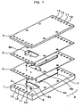
- Fig. 1 is an exploded perspective view showing a configuration of a microreactor according to an embodiment.
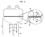
- Fig. 2 is a partial plan view showing the configuration of the microreactor shown in Fig. 1 , accompanied by a magnified view showing a part of the configuration.
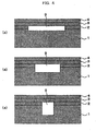
- Figs. 3A and 3B are cross-sectional views of a section where raw material introducing fluid channels and a mixing fluid channel each shown by the partial plan view of Fig. 2 overlap one another, the cross-sectional views being in parallel with a direction in which fluids flows.
- Fig. 3A is the cross-sectional view of the section taken along the a-a line of Fig. 2 .
- FIG. 3B is the cross-sectional view of the section along the b-b line of Fig.2 .
- Figs. 4C, 4D and 4E are cross-sectional views of a contraction section shown by the partial plan view of Fig. 2 .
- Fig. 4C is the cross-sectional view of the contraction section taken along the c-c line of Fig. 2 .
- Fig. 4D is the cross-sectional view of the contraction section taken along the d-d line of Fig. 2 .
- Fig. 4E is a cross-sectional view of the contraction section taken along the e-e line of Fig. 2 .
- the microreactor has a configuration in which four plates 1 to 4 are laminated.
- a lowermost plate is a base plate 1, in which raw material liquid inlet orifices 5 and 6, a raw material liquid outlet orifice 7, a raw material introducing fluid channel 8a and the base plate's mixing fluid channel 9a are formed.
- the base plate's mixing fluid channel 9a includes: a contraction section which contract a flow in its width direction, and whose cross-section becomes larger in its depth direction, as it goes downstream; and a mixing section whose a fluid channel cross-section is unchanged.
- a second plate from the bottom is a mixing fluid channel plate 2, in which the mixing fluid channel plate's mixing fluid channel 9b is formed.
- the mixing fluid channel plate's mixing fluid channel 9b is that for mixing two raw material liquids together.
- a third plate from the bottom is a raw material introducing plate 3, in which a raw material introducing fluid channel 8b is formed.
- the raw material introducing fluid channel 8b is that for introducing one of the two raw materials to the mixing fluid channel plate 2.
- a fourth plate from the bottom is an upper lid 4.
- each of the four plates has alignment holes 10 to 13 with which the four plates are aligned to one another.
- the alignment hole 10 is a hole located at a standard position, which will be described later.
- the alignment holes 10 to 13 are set in order that the positions of the base plate 1 and the raw material introducing plate 3 can shift back and forth from each other in a direction in which the fluids flow with different shifting distances.
- a series of triangular fluid channel convex portions 15 and 16 are formed in their respective downstream ends of the raw material introducing fluid channels 8a and 8b.
- the base plate 1 and the raw material introducing plate 3 are formed in a way that the two plates are laminated while shifting the apices of the fluid channel convex portion 15 from the apices of the fluid channel convex portion 16 by a half pitch in the width direction.
- the raw material introducing fluid channels 8a and 8b are aligned to the mixing fluid channel in a way that the front end of the mixing fluid channel is interposed between the upper end and the lower end of each of the fluid channel convex portions.
- a first one of the two fluids flows into the mixing fluid channel 9 in a direction indicated by an arrow 14 in Fig. 2 via the fluid channel convex portion 15 of the raw material introducing channel 8a, and a second one of the two fluids flows into the mixing fluid channel 9 in the direction indicated by the arrow 14 in Fig. 2 via the fluid channel convex portion 16 of the raw material introducing channel 8b.
- the first fluid flows into the mixing fluid channel 9 from the raw material introducing channel 8a, but no second fluid flows into the mixing fluid channel 9 from the raw material introducing fluid channel 8b, as shown in Fig. 3A .
- the second fluid flows into the mixing fluid channel 9 from the raw material introducing fluid channel 8b, but no first fluid flows into the mixing fluid channel 9 from the raw material introducing fluid channel 8a, as shown in Fig. 3B . Consequently, the two fluids flow into the mixing fluid channel 9 alternately from the raw material introducing fluid channel 8a and 8b along the arrangement of the fluid channel convex portions 15 and 16 respectively at the ends of the raw material introducing fluid channels.
- the two different fluids form a laminar flow in which the two fluids are arranged alternately in the width direction.
- a contraction flow section 17 in the mixing fluid channel makes the flow narrower in its width direction as it goes downstream by contraction flow. Furthermore, in a contraction section 18 in the mixing fluid channel, the fluid channel becomes narrower as it goes downstream, in common with the contraction flow section 17. On the other hand, the fluid channel becomes deeper as it goes downstream due to the base plate's mixing fluid channel 9a whose cross-section of the fluid channel becomes larger in the depth direction as it goes downstream, as shown in Fig.4 . That is because the mixing fluid channel 9 as a whole is configured of the base plate's mixing fluid channel 9a formed in the base plate 1 and the mixing fluid channel plate's mixing fluid channel 9b formed in the mixing fluid channel plate 2. In a mixing section 19 in the mixing fluid channel following the contraction section 18, the cross-section of the fluid channel is unchanged.
- the foregoing structure makes it easier to process the mixing fluid channel 9, because only the depth of the base plate's mixing fluid channel 9a needs to be changed.
- the mixing fluid channel's contraction section 18 reduces intervals between two neighboring laminar flows each configured of the two different fluids in the width direction, and thus decreases the diffusion distance, accordingly increases the mixing speed at which the two different fluids are mixed together due to the diffusion.
- the mixing fluid channel's contraction section 18 is designed to become deeper as it goes downstream. For this reason, the contraction section 18 is capable of holding the pressure loss of the fluid channel to a lower level with the progressively increasing depth and the contraction flow in its width direction than only with the contraction flow in its width direction. Furthermore, the contraction section 18 decreases the flow velocity because of the progressively increasing sectional area of the fluid channel.
- the length of the fluid channel needed for the mixture in the mixing fluid channel's mixing section 19 can be shortened with the decreased flow velocity than with the unchanged flow velocity. This makes it possible to reduce the pressure loss further.
- the cross-section in the most downstream part of the mixing fluid channel's contraction section 18 should be more than twice as large in depth as the cross-section in the upstream part thereof, and that a ratio of the depth to the width of the fluid channel in the most downstream part thereof should be not smaller than 1:1.
- the cross-sectional form of the contraction section should be changed with the sectional area of the contraction section remaining constant. This makes it possible to provide a microreactor making the pressure loss lower, and enables the microreactor to deal with object fluids larger in amount and higher in viscosity than a microreactor of a conventional type does.
- Fig. 5 is a partial plan view showing a configuration of a microreactor which is obtained when the positions in which the respective plates are laminated are changed, accompanied by a magnified view showing a part of the configuration.
- Figs. 6A and 6B are cross-sectional views of a nozzle section shown in the partial plan view of Fig. 5 , the cross-sectional views being in parallel with a direction in which the fluids flow.
- Fig. 6A is the cross-sectional view of the nozzle section taken along the a-a line of Fig. 5 .
- Fig. 6B is the cross-sectional view of the nozzle section along the b-b line of Fig.5 .
- the base plate 1 is moved from the position in which the base plate 1 is originally aligned to the mixing fluid channel plate 2 in the case shown in Fig. 2 in a direction opposite to a direction in which the fluids flow, whereas the raw material introducing plate 3 is moved from the position in which the raw material introducing plate 3 is originally aligned to the mixing fluid channel plate 2 in the case shown in Fig. 2 in the same direction as the fluids flow.
- the opening portion through which one of the fluids flows from the raw material introducing fluid channel 8a into the mixing fluid channel 9 is smaller in size
- the opening portion through which the other of the fluids flows from the raw material introducing fluid channel 8b into the mixing fluid channel 9 is larger in size.
- the pressure of each of the opening portions for one of the two fluids is equal to the pressure of each of the opening portions for the other of the two fluids, or the pressures respectively of the starting points of the laminar flows are equal to each other.
- the widths respectively of the two fluids in each laminar flow are uniquely determined depending on the flow rates and viscosities of the two fluids. If these widths are different from the widths of the opening portions to a large extent, however, this difference makes it difficult to form the laminar flows stably.
- the size of an opening in each section from which a fluid with a smaller flow rate is introduced has to be smaller than the size of an opening in each section from which a fluid with a larger flow rate is introduced.
- the size of an opening in each section from which one of the two different fluids is introduced are capable of being controlled by selecting one of the alignment holes while changing neither designs nor processes. This makes it possible for the microreactor to flexibly deal with two different fluids in a combination of their respective flow rates and viscosities.
- FIG. 7 is a partial plan view of laminated plates in the microreactor according to this embodiment, accompanied by a magnified view of a part of the laminated plates.
- the downstream ends of the raw material introducing fluid channels are provided respectively with a series of semi-circular fluid channel convex portions 21 and 22.
- Two different fluids flow alternately into the mixing fluid channel from the respective raw material introducing fluid channels 8a and 8b in a direction indicated by an arrow 20. This forms laminar flows in the width direction.
- downstream ends respectively of the raw material introducing fluid channels bring about a similar effect as long as the downstream ends are formed in an alternate series of concaves and convexes in the width direction. In a case where, however, the sizes of the openings are changed by changing the laminating position, it is desirable that the downstream ends should be tapered in the downstream direction.
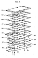
- Fig. 8 is an exploded perspective view showing a configuration of a microreactor according to still another embodiment.
- Fig. 9 is a partial plan view showing the configuration of the microreactor shown in Fig. 8 , accompanied by a magnified view of a part of the configuration.
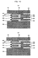
- Figs. 10A and 10B are cross-sectional views of a section where raw material introducing fluid channels and mixing fluid channels each shown by the partial plan view of Fig. 8 overlap one another, the cross-sectional views obtained while viewed from a direction in which fluids flows.
- Fig. 10A is the cross-sectional view of the section taken along the line a-a of Fig. 9 .
- Fig. 10B is the cross-sectional view of the section taken along the line b-b of Fig. 9 .
- Two sets each obtained by laminating a raw material introducing plate 40, a mixing fluid channel plate 50 and a raw material introducing plate 60 are superimposed one on another with another mixing fluid plate 50 interposed between each neighboring sets on a base plate 30 which is the lowermost part of the laminated structure.
- An upper lid 70 is superimposed on the top of the laminated structure.
- the mixing fluid channel 34 includes: a contraction section which contracts the flow in the width direction, and whose cross-section becomes larger as it goes downstream; and a mixing section in which the fluid channel cross-section of the fluid channel is unchanged.
- An inlet orifice 41, a raw material introducing fluid channel 42 and a mixing fluid channel 43 for the raw material liquids are formed in the raw material introducing plate 40.
- Inlet orifices 51 and 52, and a mixing fluid channel 53 for the raw material liquids are formed in the mixing fluid channel plate 50.
- a raw material introducing fluid channel 61 as well as an inlet orifice 62 and a mixing fluid channel 63 for the raw material liquids are formed in the raw material introducing plate 60.
- Fluid channel convex portions 45 and 65 are formed respectively in the downstream ends of the raw material introducing fluid channels 42 and 61.
- each raw material introducing plate 40 and its neighboring raw material introducing plate 60 are formed in a way that the plates are laminated while shifting the apices of the fluid channel convex portion 45 from the apices of the fluid channel convex portion 65 by a half pitch in the width direction.
- the raw material introducing fluid channels 40 and 60 are aligned to the mixing fluid channel 53 in the mixing fluid channel plate 50 in a way that the mixing fluid channel is interposed between the upper end and the lower end of each of the fluid channel convex portions.
- a first one of the two fluids flows into the mixing fluid channel 53 in the mixing fluid channel plate 50 in a direction indicated by an arrow 14 in Fig. 9 via the fluid channel convex portion 45 in the raw material introducing channel 42, and a second one of the two fluids flows into the mixing fluid channel 53 in the mixing fluid channel 50 in the direction indicated by the arrow 14 in Fig. 9 via the fluid channel convex portion 65 in the raw material introducing channel 61.
- the first fluid flows into the mixing fluid channel 53 from the raw material introducing channel 42, but no second fluid flows into the mixing fluid channel 53 from the raw material introducing fluid channel 61, as shown in Fig. 10A .
- the second fluid flows into the mixing fluid channel 53 from the raw material introducing fluid channel 61, but no first fluid flows into the mixing fluid channel 53 from the raw material introducing fluid channel 42, as shown in Fig. 10B .
- the two fluids flow into the mixing fluid channel 33 alternately from the raw material introducing fluid channel 42 and 61 along the arrangement of the fluid channel convex portions 45 and 65 respectively at the ends of the raw material introducing fluid channels.
- the mixing fluid channel 53 is combined with the mixing fluid channel 43 and 63, and thus into a mixing fluid channel 83.
- the two different fluids form a laminar flow in which the two fluids are arranged alternately in the width direction.
- laminar flows are intended to be formed in the width direction by alternately introducing multiple different fluids to the mixing fluid channel from above and under via the respective raw material introducing channels, it is difficult to form laminar flows which are homogeneous in the depth direction if the width of each of the laminar flows becomes smaller than the depth of the mixing fluid channel. For this reason, the depth of an upstream part of the mixing fluid channels for forming laminar flows has to be designed to be smaller than the width of each of the laminar flows. This presents one of causes of making the pressure loss larger.
- mixing fluid channels each with a sufficiently small depth are laminated and combined together as they are in the section for forming laminar flows. This makes it possible for the microreactor to form stable laminar flows even though the laminar flows are large in the depth direction, and to reduce the pressure loss.
- the microreactor according to the present invention is applicable to mixture of fluids each larger in amount and higher in viscosity.
Landscapes
- Chemical & Material Sciences (AREA)
- Chemical Kinetics & Catalysis (AREA)
- Dispersion Chemistry (AREA)
- Organic Chemistry (AREA)
- Physical Or Chemical Processes And Apparatus (AREA)
Claims (5)
- Mikroreaktor zum Vermischen und Ausstoßen von zwei Rohmaterialflüssigkeiten, wobei der Mikroreaktor durch Laminieren einer Grundplatte (1), einer Rohmaterial-Einführungsplatte (3) und einer Vermischungsfluid-Kanalplatte (2) erhalten wird, die Grundplatte (1) einen ersten Rohmaterial-Einführungsfluidkanal (8a) zum Einführen von einer der beiden darin gebildeten Rohmaterialflüssigkeiten aufweist, die Vermischungsfluid-Kanalplatte (2) zwischen der Grundplatte (1) und der Rohmaterial-Einführungsplatte (3) angeordnet ist und die Vermischungsfluid-Kanalplatte (2) einen Vermischungsfluidkanal (9b) zum Vermischen der beiden darin gebildeten Rohmaterialflüssigkeiten aufweist,
wobei der Mikroreaktor Folgendes umfasst:einen Vermischungsfluidkanal (9b) in der Vermischungsfluid-Kanalplatte (2), der in der Vermischungsfluid-Kanalplatte (2) ausgebildet ist und in dem eine Strömung in Breitenrichtung zusammengezogen wird;wobei der Querschnitt des Vermischungsfluidkanals (9) in Tiefenrichtung größer wird, wenn er stromabwärts geht,wobei der Vermischungsfluidkanal (9) mit einer Auslassöffnung (7) verbunden ist, aus der die vermischten Rohmaterialflüssigkeiten ausgestoßen werden sollen, dadurch gekennzeichnet, dassdie Rohmaterial-Einführungsplatte (3) einen zweiten Rohmaterial-Einführungsfluidkanal (8b) zum Einführen der anderen der beiden darin gebildeten Rohmaterialflüssigkeiten aufweist,ein Vermischungsfluidkanal (9a) in der Grundplatte (1) in der Grundplatte (1) ausgebildet ist,der Vermischungsfluidkanal (9a) in der Grundplatte (1) mit dem Vermischungsfluidkanal (9b) in der Vermischungsfluid-Kanalplatte (2) in Verbindung steht, unddie Grundplatte (1) und die Rohmaterial-Einführungsplatte (3) mehrere Ausrichtungslöcher (10, 11, 12, 13) zum Einstellen von Vorwärts/Rückwärts-Versetzungsbeträgen umfassen und die Größe einer Öffnung in den Vermischungsfluidkanal (9b) in der Vermischungsfluid-Kanalplatte (2) von dem ersten Rohmaterial-Einführungsfluidkanal (8a) und die Größe einer Öffnung in den Vermischungsfluidkanal (9b) in der Vermischungsfluid-Kanalplatte (2) von dem zweiten Rohmaterial-Einführungsfluidkanal (8b) durch Auswählen eines Ausrichtungslochs (10, 11, 12, 13), das zur Ausrichtung verwendet werden soll, eingestellt wird. - Mikroreaktor nach Anspruch 1, wobei die Grundplatte (1) jeweils Einlassöffnungen (5, 6) für die Rohmaterialflüssigkeiten und eine Auslassöffnung (7) für vermischte Flüssigkeiten beinhaltet.
- Mikroreaktor nach Anspruch 1 oder 2, wobei
Fluidkanäle, von denen jeder eine dreieckige Form besitzt, in stromabwärtigen Enden der Rohmaterial-Einführungsfluidkanäle (8a, 8b) ausgebildet sind, und
Öffnungen der jeweiligen Rohmaterial-Einführungsfluidkanäle (8a, 8b) in den Vermischungsfluidkanal (9b) in der Größe geändert werden können, indem Vorwärts-/Rückwärts-Versetzungsbeträge der Grundplatte (1) und der Rohmaterial-Einführungsplatte (3) geändert werden. - Mikroreaktor nach Anspruch 1 oder 2, wobei
Fluidkanäle, von denen jeder eine Halbkreisform besitzt, in stromabwärtigen Enden der Rohmaterial-Einführungsfluidkanäle (8a, 8b) ausgebildet sind, und
Öffnungen der jeweiligen Rohmaterial-Einführungsfluidkanäle (8a, 8b) in den Vermischungsfluidkanal (9b) in der Größe geändert werden können, indem Vorwärts-/Rückwärts-Versetzungsbeträge der Grundplatte (1) und der Rohmaterial-Einführungsplatte (3) geändert werden. - Mikroreaktor nach Anspruch 1 oder 4, wobei eine Querschnittsfläche des Vermischungsfluidkanals (9a) in der Grundplatte (1) im Wesentlichen konstant gehalten wird, während die Tiefenrichtung größer wird.
Applications Claiming Priority (1)
| Application Number | Priority Date | Filing Date | Title |
|---|---|---|---|
| JP2006274578A JP4677969B2 (ja) | 2006-10-06 | 2006-10-06 | マイクロリアクタ |
Publications (3)
| Publication Number | Publication Date |
|---|---|
| EP1908514A2 EP1908514A2 (de) | 2008-04-09 |
| EP1908514A3 EP1908514A3 (de) | 2009-07-15 |
| EP1908514B1 true EP1908514B1 (de) | 2011-04-13 |
Family
ID=38921102
Family Applications (1)
| Application Number | Title | Priority Date | Filing Date |
|---|---|---|---|
| EP07015620A Not-in-force EP1908514B1 (de) | 2006-10-06 | 2007-08-08 | Mikroreaktor |
Country Status (4)
| Country | Link |
|---|---|
| US (1) | US7850930B2 (de) |
| EP (1) | EP1908514B1 (de) |
| JP (1) | JP4677969B2 (de) |
| DE (1) | DE602007013849D1 (de) |
Families Citing this family (13)
| Publication number | Priority date | Publication date | Assignee | Title |
|---|---|---|---|---|
| CN102065987A (zh) * | 2008-06-18 | 2011-05-18 | 纳幕尔杜邦公司 | 具有波纹输送板的混合装置 |
| JP5081845B2 (ja) | 2009-02-10 | 2012-11-28 | 株式会社日立製作所 | 粒子製造装置 |
| GB2469087A (en) * | 2009-04-02 | 2010-10-06 | Ct Angewandte Nanotech Can | Preparation of colloidal dispersion |
| KR101569836B1 (ko) * | 2009-10-28 | 2015-11-17 | 삼성전자주식회사 | 미세 유체 소자의 초기화 방법, 미세 유체 소자의 초기화 장치 및 미세 유체 소자 패키지 |
| US8757444B2 (en) | 2009-12-17 | 2014-06-24 | Actamax Surgical Materials, Llc | Dispensing device having an array of laterally spaced tubes |
| JP6006969B2 (ja) * | 2012-04-24 | 2016-10-12 | 東芝機械株式会社 | マイクロミキサー、マイクロミキサーエレメントおよびその製造方法 |
| GB201416283D0 (en) * | 2014-09-15 | 2014-10-29 | Norprocess As | Enzymatic processing plant and method of enzymatic processing |
| US9855382B2 (en) * | 2015-03-31 | 2018-01-02 | Biomet Biologics, Llc | Cell washing device using standing acoustic waves and a phantom material |
| US10737012B2 (en) | 2015-03-31 | 2020-08-11 | Biomet Biologics, Inc. | Cell washing using acoustic waves |
| CN115155480B (zh) | 2017-07-31 | 2023-09-29 | 康宁股份有限公司 | 改进的工艺强化流反应器 |
| US20210008509A1 (en) * | 2019-07-09 | 2021-01-14 | Imagine Tf, Llc | Parallel production of emulsification |
| JP7562468B2 (ja) * | 2021-04-05 | 2024-10-07 | Ckd株式会社 | マイクロミキサ |
| CN113145037B (zh) * | 2021-04-08 | 2022-11-18 | 复旦大学 | 一种微流体分布器及多通道并行放大的流体均匀分布方法 |
Family Cites Families (15)
| Publication number | Priority date | Publication date | Assignee | Title |
|---|---|---|---|---|
| US5842787A (en) * | 1997-10-09 | 1998-12-01 | Caliper Technologies Corporation | Microfluidic systems incorporating varied channel dimensions |
| DE19927554C2 (de) * | 1999-06-16 | 2002-12-19 | Inst Mikrotechnik Mainz Gmbh | Mikromischer |
| US7241423B2 (en) * | 2000-02-03 | 2007-07-10 | Cellular Process Chemistry, Inc. | Enhancing fluid flow in a stacked plate microreactor |
| DE10041823C2 (de) * | 2000-08-25 | 2002-12-19 | Inst Mikrotechnik Mainz Gmbh | Verfahren und statischer Mikrovermischer zum Mischen mindestens zweier Fluide |
| US6863867B2 (en) * | 2001-05-07 | 2005-03-08 | Uop Llc | Apparatus for mixing and reacting at least two fluids |
| DE10123093A1 (de) * | 2001-05-07 | 2002-11-21 | Inst Mikrotechnik Mainz Gmbh | Verfahren und statischer Mikrovermischer zum Mischen mindestens zweier Fluide |
| US7097347B2 (en) * | 2001-05-07 | 2006-08-29 | Uop Llc | Static mixer and process for mixing at least two fluids |
| JP2003047839A (ja) | 2001-08-06 | 2003-02-18 | Yamatake Corp | マイクロリアクタ |
| US20040109793A1 (en) * | 2002-02-07 | 2004-06-10 | Mcneely Michael R | Three-dimensional microfluidics incorporating passive fluid control structures |
| DE20206371U1 (de) | 2002-04-23 | 2002-06-27 | Ehrfeld Mikrotechnik GmbH, 55234 Wendelsheim | Modular aufgebauter statischer Mikrovermischer |
| JP2005083505A (ja) * | 2003-09-09 | 2005-03-31 | Olympus Corp | スライド式バルブ装置 |
| US7588671B2 (en) * | 2003-11-21 | 2009-09-15 | Ebara Corporation | Microfluidic treatment method and device |
| JP2006102649A (ja) * | 2004-10-06 | 2006-04-20 | Hitachi Industries Co Ltd | マイクロ流体装置 |
| TWI247626B (en) * | 2004-08-06 | 2006-01-21 | Hitachi Ind Co Ltd | Micro fluid chip |
| JP4403943B2 (ja) * | 2004-10-07 | 2010-01-27 | 株式会社日立プラントテクノロジー | 流体混合器及びマイクロリアクタシステム |
-
2006
- 2006-10-06 JP JP2006274578A patent/JP4677969B2/ja not_active Expired - Fee Related
-
2007
- 2007-08-08 DE DE602007013849T patent/DE602007013849D1/de active Active
- 2007-08-08 EP EP07015620A patent/EP1908514B1/de not_active Not-in-force
- 2007-08-08 US US11/835,439 patent/US7850930B2/en not_active Expired - Fee Related
Also Published As
| Publication number | Publication date |
|---|---|
| US20080085227A1 (en) | 2008-04-10 |
| US7850930B2 (en) | 2010-12-14 |
| EP1908514A2 (de) | 2008-04-09 |
| DE602007013849D1 (de) | 2011-05-26 |
| JP2008093498A (ja) | 2008-04-24 |
| JP4677969B2 (ja) | 2011-04-27 |
| EP1908514A3 (de) | 2009-07-15 |
Similar Documents
| Publication | Publication Date | Title |
|---|---|---|
| EP1908514B1 (de) | Mikroreaktor | |
| EP1997553B1 (de) | Flüssigkeitsmischer und Verfahren zum Bilden von gemischter Flüssigkeit | |
| JP6204235B2 (ja) | プロセス強化マイクロ流体装置 | |
| JP5604038B2 (ja) | 反応装置及び反応プラント | |
| JP4339163B2 (ja) | マイクロデバイスおよび流体の合流方法 | |
| EP2089144B1 (de) | Mikromischkammer, Mikromischer mit mehreren derartigen Mikromischkammern und Verfahren zur Herstellung davon | |
| CN102958588B (zh) | 微混合器 | |
| US20090092526A1 (en) | Micro-channels, micro-mixers, and micro-reactors | |
| JP4403943B2 (ja) | 流体混合器及びマイクロリアクタシステム | |
| EP2113558B1 (de) | Mikroreaktor | |
| JP3810778B2 (ja) | 平板静止型混合器 | |
| JP4367283B2 (ja) | マイクロ流体チップ | |
| KR20180109955A (ko) | 중공 챔버 x-믹서 열교환기 | |
| JP4226634B2 (ja) | マイクロリアクター | |
| JP2009018311A (ja) | マイクロ流体チップ | |
| JP2004016870A (ja) | マイクロリアクター及びそれを用いた化学反応方法 | |
| EP1854536A1 (de) | Hoch-Durchsatz Mikroreaktoren mit Temperaturkontrolle und Verfahren | |
| US9656235B2 (en) | Operation method for multichannel apparatus and multichannel apparatus | |
| KR100658361B1 (ko) | 마이크로 채널 리액터 | |
| KR102114778B1 (ko) | 미세혼합기 | |
| JP4298671B2 (ja) | マイクロデバイス | |
| WO2013165908A1 (en) | Micro-channels, micro-mixers and micro-reactors | |
| JP2006255584A (ja) | マイクロリアクタ | |
| JP2009233514A (ja) | マイクロ化学反応装置及びマイクロ化学反応システム | |
| JP2005131503A (ja) | 増設流路モジュールおよび流体混合器 |
Legal Events
| Date | Code | Title | Description |
|---|---|---|---|
| PUAI | Public reference made under article 153(3) epc to a published international application that has entered the european phase |
Free format text: ORIGINAL CODE: 0009012 |
|
| AK | Designated contracting states |
Kind code of ref document: A2 Designated state(s): AT BE BG CH CY CZ DE DK EE ES FI FR GB GR HU IE IS IT LI LT LU LV MC MT NL PL PT RO SE SI SK TR |
|
| AX | Request for extension of the european patent |
Extension state: AL BA HR MK RS |
|
| 17P | Request for examination filed |
Effective date: 20090422 |
|
| PUAL | Search report despatched |
Free format text: ORIGINAL CODE: 0009013 |
|
| AK | Designated contracting states |
Kind code of ref document: A3 Designated state(s): AT BE BG CH CY CZ DE DK EE ES FI FR GB GR HU IE IS IT LI LT LU LV MC MT NL PL PT RO SE SI SK TR |
|
| AX | Request for extension of the european patent |
Extension state: AL BA HR MK RS |
|
| 17Q | First examination report despatched |
Effective date: 20091120 |
|
| AKX | Designation fees paid |
Designated state(s): CH DE LI SE |
|
| GRAP | Despatch of communication of intention to grant a patent |
Free format text: ORIGINAL CODE: EPIDOSNIGR1 |
|
| GRAS | Grant fee paid |
Free format text: ORIGINAL CODE: EPIDOSNIGR3 |
|
| GRAA | (expected) grant |
Free format text: ORIGINAL CODE: 0009210 |
|
| AK | Designated contracting states |
Kind code of ref document: B1 Designated state(s): CH DE LI SE |
|
| REG | Reference to a national code |
Ref country code: CH Ref legal event code: EP |
|
| RAP2 | Party data changed (patent owner data changed or rights of a patent transferred) |
Owner name: HITACHI PLANT TECHNOLOGIES, LTD. |
|
| REF | Corresponds to: |
Ref document number: 602007013849 Country of ref document: DE Date of ref document: 20110526 Kind code of ref document: P |
|
| REG | Reference to a national code |
Ref country code: DE Ref legal event code: R096 Ref document number: 602007013849 Country of ref document: DE Effective date: 20110526 |
|
| REG | Reference to a national code |
Ref country code: CH Ref legal event code: NV Representative=s name: TROESCH SCHEIDEGGER WERNER AG |
|
| REG | Reference to a national code |
Ref country code: SE Ref legal event code: TRGR |
|
| PGFP | Annual fee paid to national office [announced via postgrant information from national office to epo] |
Ref country code: CH Payment date: 20110901 Year of fee payment: 5 |
|
| REG | Reference to a national code |
Ref country code: SE Ref legal event code: RPOT |
|
| PGFP | Annual fee paid to national office [announced via postgrant information from national office to epo] |
Ref country code: DE Payment date: 20110831 Year of fee payment: 5 Ref country code: SE Payment date: 20110824 Year of fee payment: 5 |
|
| PLBE | No opposition filed within time limit |
Free format text: ORIGINAL CODE: 0009261 |
|
| STAA | Information on the status of an ep patent application or granted ep patent |
Free format text: STATUS: NO OPPOSITION FILED WITHIN TIME LIMIT |
|
| 26N | No opposition filed |
Effective date: 20120116 |
|
| REG | Reference to a national code |
Ref country code: DE Ref legal event code: R097 Ref document number: 602007013849 Country of ref document: DE Effective date: 20120116 |
|
| REG | Reference to a national code |
Ref country code: CH Ref legal event code: PL |
|
| REG | Reference to a national code |
Ref country code: SE Ref legal event code: EUG |
|
| PG25 | Lapsed in a contracting state [announced via postgrant information from national office to epo] |
Ref country code: CH Free format text: LAPSE BECAUSE OF NON-PAYMENT OF DUE FEES Effective date: 20120831 Ref country code: SE Free format text: LAPSE BECAUSE OF NON-PAYMENT OF DUE FEES Effective date: 20120809 Ref country code: LI Free format text: LAPSE BECAUSE OF NON-PAYMENT OF DUE FEES Effective date: 20120831 |
|
| PG25 | Lapsed in a contracting state [announced via postgrant information from national office to epo] |
Ref country code: DE Free format text: LAPSE BECAUSE OF NON-PAYMENT OF DUE FEES Effective date: 20130301 |
|
| REG | Reference to a national code |
Ref country code: DE Ref legal event code: R119 Ref document number: 602007013849 Country of ref document: DE Effective date: 20130301 |