EP1908435A1 - Mouth cleaning device - Google Patents
Mouth cleaning device Download PDFInfo
- Publication number
- EP1908435A1 EP1908435A1 EP07019538A EP07019538A EP1908435A1 EP 1908435 A1 EP1908435 A1 EP 1908435A1 EP 07019538 A EP07019538 A EP 07019538A EP 07019538 A EP07019538 A EP 07019538A EP 1908435 A1 EP1908435 A1 EP 1908435A1
- Authority
- EP
- European Patent Office
- Prior art keywords
- current
- electrode
- cleaning device
- flow
- mouth cleaning
- Prior art date
- Legal status (The legal status is an assumption and is not a legal conclusion. Google has not performed a legal analysis and makes no representation as to the accuracy of the status listed.)
- Granted
Links
- 238000004140 cleaning Methods 0.000 title claims abstract description 11
- QVGXLLKOCUKJST-UHFFFAOYSA-N atomic oxygen Chemical compound [O] QVGXLLKOCUKJST-UHFFFAOYSA-N 0.000 description 10
- 229910052760 oxygen Inorganic materials 0.000 description 10
- 239000001301 oxygen Substances 0.000 description 10
- 102000001554 Hemoglobins Human genes 0.000 description 6
- 108010054147 Hemoglobins Proteins 0.000 description 6
- 239000002184 metal Substances 0.000 description 4
- 238000010586 diagram Methods 0.000 description 3
- 239000000463 material Substances 0.000 description 3
- 206010061218 Inflammation Diseases 0.000 description 2
- 230000000740 bleeding effect Effects 0.000 description 2
- 230000001680 brushing effect Effects 0.000 description 2
- 230000000694 effects Effects 0.000 description 2
- 230000004054 inflammatory process Effects 0.000 description 2
- 101001020552 Rattus norvegicus LIM/homeobox protein Lhx1 Proteins 0.000 description 1
- 230000000903 blocking effect Effects 0.000 description 1
- 230000017531 blood circulation Effects 0.000 description 1
- 210000004204 blood vessel Anatomy 0.000 description 1
- 238000010828 elution Methods 0.000 description 1
- 230000002708 enhancing effect Effects 0.000 description 1
- 210000003743 erythrocyte Anatomy 0.000 description 1
- 230000004060 metabolic process Effects 0.000 description 1
- 230000004048 modification Effects 0.000 description 1
- 238000012986 modification Methods 0.000 description 1
- 230000004936 stimulating effect Effects 0.000 description 1
Images


Classifications
-
- A—HUMAN NECESSITIES
- A61—MEDICAL OR VETERINARY SCIENCE; HYGIENE
- A61C—DENTISTRY; APPARATUS OR METHODS FOR ORAL OR DENTAL HYGIENE
- A61C17/00—Devices for cleaning, polishing, rinsing or drying teeth, teeth cavities or prostheses; Saliva removers; Dental appliances for receiving spittle
- A61C17/16—Power-driven cleaning or polishing devices
- A61C17/22—Power-driven cleaning or polishing devices with brushes, cushions, cups, or the like
-
- A—HUMAN NECESSITIES
- A46—BRUSHWARE
- A46B—BRUSHES
- A46B15/00—Other brushes; Brushes with additional arrangements
- A46B15/0002—Arrangements for enhancing monitoring or controlling the brushing process
-
- A—HUMAN NECESSITIES
- A46—BRUSHWARE
- A46B—BRUSHES
- A46B15/00—Other brushes; Brushes with additional arrangements
- A46B15/0002—Arrangements for enhancing monitoring or controlling the brushing process
- A46B15/0016—Arrangements for enhancing monitoring or controlling the brushing process with enhancing means
- A46B15/0022—Arrangements for enhancing monitoring or controlling the brushing process with enhancing means with an electrical means
-
- A—HUMAN NECESSITIES
- A61—MEDICAL OR VETERINARY SCIENCE; HYGIENE
- A61C—DENTISTRY; APPARATUS OR METHODS FOR ORAL OR DENTAL HYGIENE
- A61C17/00—Devices for cleaning, polishing, rinsing or drying teeth, teeth cavities or prostheses; Saliva removers; Dental appliances for receiving spittle
-
- A—HUMAN NECESSITIES
- A46—BRUSHWARE
- A46B—BRUSHES
- A46B2200/00—Brushes characterized by their functions, uses or applications
- A46B2200/10—For human or animal care
- A46B2200/1066—Toothbrush for cleaning the teeth or dentures
-
- A—HUMAN NECESSITIES
- A61—MEDICAL OR VETERINARY SCIENCE; HYGIENE
- A61N—ELECTROTHERAPY; MAGNETOTHERAPY; RADIATION THERAPY; ULTRASOUND THERAPY
- A61N1/00—Electrotherapy; Circuits therefor
- A61N1/18—Applying electric currents by contact electrodes
- A61N1/20—Applying electric currents by contact electrodes continuous direct currents
- A61N1/26—Electromedical brushes; Electromedical massage devices ; Combs
Definitions
- a conventional mouth cleaning device an electric toothbrush or an ion toothbrush has been known.
- the conventional mouth cleaning device removes plaque from teeth by flowing a minute current in a mouth, thereby enhancing cleaning effect of brushing, metabolism of oral tissues or blood flow.
- Japanese Patent No. 2560162 describes therein a toothbrush including a head portion where bristles are arranged and a handle portion where a battery is accommodated, wherein an electrode connected with one pole of the battery is arranged on a part of a surface of the handle portion, whereas an electrode connected with the other pole of the battery is arranged on the head portion.
- the pulse current has a frequency of about 9090 Hz.
- the present invention in which the pulse current having the frequency of about 4000 Hz to about 15000 Hz is made to flow is efficient in stimulating gum tissues and improving gum health.
- the electrode 23 is connected with the positive pole of the battery 20 via an output resistor Ro1 and a boosting circuit 3 mounted on the circuit board 24. Further, the electrode 13 of the head portion 1 is connected with the grounded negative pole of the battery 20 via a conduction plate 12 installed inside the shaft 11, the driving shaft 21, and the circuit board 24 (i.e., an output resistor RO2, a current limit transistor TRa and limit resistor Rlim 2 mounted thereon).
- a conduction plate 12 installed inside the shaft 11, the driving shaft 21, and the circuit board 24 (i.e., an output resistor RO2, a current limit transistor TRa and limit resistor Rlim 2 mounted thereon).
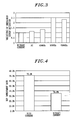
- Fig. 3 shows variations in hemoglobin oxygen saturation obtained when a pulsed current, a DC current, and no current are made to flow, wherein the saturation values are normalized with respect to the value obtained when no current is made to flow.
- the hemoglobin oxygen saturation indicates a combination ratio between oxygen and hemoglobin in red blood cells flowing through gum blood vessels. Since the oxygen sufficiency in tissues can be monitored by measuring the hemoglobin oxygen saturation, it serves as an indicator representing a state of inflammation of gums. When the state of gum health is poor due to the inflammation of gums or the like, oxygen supply cannot meet oxygen demand and, accordingly, oxygen becomes insufficient (low hemoglobin oxygen saturation).
- the saturation is higher when the DC current is made to flow than when no current is made to flow.
- the saturation becomes further higher when a pulsed current of about 4545 Hz is made to flow, and highest when a pulse current of 9090 Hz is made to flow.
- the saturation is smaller when a pulsed current of 15000 Hz is made to flow than when the pulsed current of 9090 Hz is made to flow.
- the electrode 13 is a negative electrode to which a single pole pulsed current is supplied to prevent elution of an electrode metal.
- teeth or gums serve as a cathode.
- a metal of the anode is eluted, and the eluted metal is deposited on the teeth or the gums serving as the anode.
- the anode can be made of a material other than a metal or a material that is not eluted. If such a material is employed as the electrode 13, the electrode 13 can be positively biased or AC-biased.
- the actuator 22 (or another driving unit) can be omitted.
Landscapes
- Health & Medical Sciences (AREA)
- Public Health (AREA)
- Epidemiology (AREA)
- Life Sciences & Earth Sciences (AREA)
- Animal Behavior & Ethology (AREA)
- General Health & Medical Sciences (AREA)
- Dentistry (AREA)
- Veterinary Medicine (AREA)
- Brushes (AREA)
- Massaging Devices (AREA)
- Closures For Containers (AREA)
- Seal Device For Vehicle (AREA)
- Processing Of Meat And Fish (AREA)
- Sink And Installation For Waste Water (AREA)
Abstract
Description
- The present invention relates to a mouth cleaning device for improving oral hygiene by flowing a minute current in a mouth.
- As for a conventional mouth cleaning device, an electric toothbrush or an ion toothbrush has been known. The conventional mouth cleaning device removes plaque from teeth by flowing a minute current in a mouth, thereby enhancing cleaning effect of brushing, metabolism of oral tissues or blood flow. For example,
Japanese Patent No. 2560162 No. S62-30849 - However, the conventional toothbrush is not efficient in massaging gum tissues.
- In view of the above, the present invention provides a mouth cleaning device that is efficient in massaging gum tissues.
- In accordance with an embodiment of the present invention, there is provided a mouth cleaning device including: a head portion provided with bristles and an electrode and a handle portion provided with an electrode, wherein when an electric circuit is formed from one electrode to the other electrode via a human body by application of a voltage to the electrodes, a pulse current having a frequency of about 4000 Hz to about 15000 Hz flows therein.
- Preferably, the pulse current has a frequency of about 9090 Hz.
- The present invention in which the pulse current having the frequency of about 4000 Hz to about 15000 Hz is made to flow is efficient in stimulating gum tissues and improving gum health.
- The objects and features of the present invention will become apparent from the following description of embodiments, given in conjunction with the accompanying drawings, in which:
- Fig. 1 shows a block circuit diagram of an exemplary embodiment of the present invention;
- Fig. 2 is a cross sectional view of an exemplary toothbrush of the present invention;
- Fig. 3 illustrates an explanatory diagram for explaining exemplary variations in hemoglobin oxygen saturation of the embodiment of the present invention to; and
- Fig. 4 provides an explanatory diagram for explaining variations in an exemplary BOP (Bleeding On Probing) improvement rate of the embodiment of the present invention.
- The embodiments of the present invention will be described with reference to the accompanying drawings which form a part hereof. Referring to Fig. 2, there are illustrated a
head portion 1 formed by arrangingbristles 10 on one end side of ashaft 11 and ahandle portion 2 accommodating therein a power source (e.g., battery or the like) 20. Thehandle portion 2 includes therein adriving shaft 21 having one end connected with thehead portion 1, anactuator 22 for moving thedriving shaft 21 in an axial reciprocating motion or the like, and acircuit board 24. Moreover, thehandle portion 2 has anelectrode 23 on an outer surface thereof, and thehead portion 1 has anelectrode 13 near roots of thebristles 10. - As illustrated in Fig. 1, the
electrode 23 is connected with the positive pole of thebattery 20 via an output resistor Ro1 and aboosting circuit 3 mounted on thecircuit board 24. Further, theelectrode 13 of thehead portion 1 is connected with the grounded negative pole of thebattery 20 via aconduction plate 12 installed inside theshaft 11, thedriving shaft 21, and the circuit board 24 (i.e., an output resistor RO2, a current limit transistor TRa andlimit resistor Rlim 2 mounted thereon). - The
circuit board 24 has acurrent limit circuit 4 shown in Fig. 1, in addition to theboosting circuit 3. Thecurrent limit circuit 4, which is formed of the control resistor Rlim1, the current limit transistor TRa and a limit resistor Rlim2, generates a constant base current from a reference DC voltage VR (current limit control DC voltage) via the control resistor Rlim1, and limits a collector current that can flow through the current limit transistor TRa. The control resistor Rlim1 serves to adjust the reference DC voltage VR, and can variably adjust a current limit when it is configured as a variable resistor, according to individual differences in a resistance of a human body, individual differences in reaction to a current and the like. It is preferable that the maximum value of the limited current which can flow through the human body is lower than or equal to about 300 µA. - The
boosting circuit 3 boosts a battery voltage VB and generates a voltage Vh (Vh > VB) under the control of aboost control circuit 30. This voltage Vh is preferably a voltage which allows the supply of a current of a magnitude that enables required effects to be obtained even if a resistance of a conduction path including a human body is not uniform. For example, when a current of about 100 µA needs to flow on the assumption that a maximum resistance (including a contact resistance or the like) of the path including the human body is about 150 kΩ, the voltage Vh is about 15 V (= 150 kΩ × 100 µA). - If the
handle portion 2 is held and thehead portion 1 is inserted into the mouth in a state where the voltage Vh generated by theboosting circuit 3 is applied to theelectrodes electrode 23, the human body, theelectrode 13, theconduction plate 12, thedriving shaft 21 and an output resistor Ro2. However, the current is limited to, e.g., about 100 µA, by the aforementioned base current. Therefore, even when the resistance of the human body is low, the current greater than or equal to about 100 µA does not flow and, also, an surge current can be suppressed. - As depicted in Fig. 1, there is provided a transistor TRb which temporarily blocking a current by reducing a base potential of the pulsed current limit transistor TRa to zero at regular intervals so that the current can flow through the human body.
- Fig. 3 shows variations in hemoglobin oxygen saturation obtained when a pulsed current, a DC current, and no current are made to flow, wherein the saturation values are normalized with respect to the value obtained when no current is made to flow. The hemoglobin oxygen saturation indicates a combination ratio between oxygen and hemoglobin in red blood cells flowing through gum blood vessels. Since the oxygen sufficiency in tissues can be monitored by measuring the hemoglobin oxygen saturation, it serves as an indicator representing a state of inflammation of gums. When the state of gum health is poor due to the inflammation of gums or the like, oxygen supply cannot meet oxygen demand and, accordingly, oxygen becomes insufficient (low hemoglobin oxygen saturation).
- As clearly can be seen from Fig. 3, the saturation is higher when the DC current is made to flow than when no current is made to flow. The saturation becomes further higher when a pulsed current of about 4545 Hz is made to flow, and highest when a pulse current of 9090 Hz is made to flow. However, the saturation is smaller when a pulsed current of 15000 Hz is made to flow than when the pulsed current of 9090 Hz is made to flow.
- Fig. 4 illustrates variations in BOP (Bleeding On Probing) when the pulsed current of 4545 Hz is made to flow for one month during tooth brushing and when no current is made to flow. As a result, it was found that the BOP was significantly improved when the pulsed current was made to flow. Therefore, it is clear that the gum care is effective when the pulse current of a frequency greater than or equal to about 4000 Hz is made to flow.
- The
electrode 13 is a negative electrode to which a single pole pulsed current is supplied to prevent elution of an electrode metal. When an electrode inserted into a mouth serves as an anode, teeth or gums serve as a cathode. In that case, a metal of the anode is eluted, and the eluted metal is deposited on the teeth or the gums serving as the anode. However, the anode can be made of a material other than a metal or a material that is not eluted. If such a material is employed as theelectrode 13, theelectrode 13 can be positively biased or AC-biased. - Although the
head portion 1 in the above embodiment moves by theactuator 22, the actuator 22 (or another driving unit) can be omitted. - While the invention has been shown and described with respect to the embodiments, it will be understood by those skilled in the art that various changes and modification may be made without departing from the scope of the invention as defined in the following claims.
Claims (2)
- A mouth cleaning device comprising:a head portion provided with bristles and an electrode; anda handle portion provided with an electrode, wherein when an electric circuit is formed from one electrode to the other electrode via a human body by application of a voltage to the electrodes, a pulse current having a frequency of about 4000 Hz to about 15000 Hz flows therein.
- The mouth cleaning device of claim 1, wherein the pulse current has a frequency of about 9090 Hz.
Applications Claiming Priority (1)
| Application Number | Priority Date | Filing Date | Title |
|---|---|---|---|
| JP2006275682A JP2008093039A (en) | 2006-10-06 | 2006-10-06 | Mouth cleaning device |
Publications (2)
| Publication Number | Publication Date |
|---|---|
| EP1908435A1 true EP1908435A1 (en) | 2008-04-09 |
| EP1908435B1 EP1908435B1 (en) | 2011-03-23 |
Family
ID=38819336
Family Applications (1)
| Application Number | Title | Priority Date | Filing Date |
|---|---|---|---|
| EP07019538A Not-in-force EP1908435B1 (en) | 2006-10-06 | 2007-10-05 | Mouth cleaning device |
Country Status (7)
| Country | Link |
|---|---|
| US (1) | US20080083074A1 (en) |
| EP (1) | EP1908435B1 (en) |
| JP (1) | JP2008093039A (en) |
| KR (1) | KR100924875B1 (en) |
| CN (2) | CN201171863Y (en) |
| AT (1) | ATE502597T1 (en) |
| DE (1) | DE602007013334D1 (en) |
Cited By (3)
| Publication number | Priority date | Publication date | Assignee | Title |
|---|---|---|---|---|
| EP2384664A1 (en) | 2010-05-06 | 2011-11-09 | Braun GmbH | Mouth cleaning device and head portion of a mouth cleaning device |
| JP5314675B2 (en) * | 2008-04-15 | 2013-10-16 | パナソニック株式会社 | Electronic toothbrush |
| EP2522303A4 (en) * | 2010-01-08 | 2015-04-08 | Omron Healthcare Co Ltd | ELECTRIC TOOTHBRUSH |
Families Citing this family (9)
| Publication number | Priority date | Publication date | Assignee | Title |
|---|---|---|---|---|
| JP2008093039A (en) * | 2006-10-06 | 2008-04-24 | Matsushita Electric Works Ltd | Mouth cleaning device |
| TWM322238U (en) * | 2006-11-28 | 2007-11-21 | Shy-Ming Shih | Toothbrush structure with electronic circuit |
| RU2405499C1 (en) * | 2006-12-27 | 2010-12-10 | Панасоник Электрик Воркс Ко., Лтд. | Electric toothbrush |
| JP4375482B2 (en) * | 2008-01-28 | 2009-12-02 | パナソニック電工株式会社 | Toothbrush device |
| JP5246089B2 (en) * | 2009-07-28 | 2013-07-24 | パナソニック株式会社 | Gum massage brush and gum massage device |
| US9009901B2 (en) * | 2011-09-20 | 2015-04-21 | Braun Gmbh | Oral care devices having automatic mode selection |
| EP2976965A1 (en) * | 2014-07-22 | 2016-01-27 | Braun GmbH | Fastenable device for oral cavity position detection |
| JP6369899B2 (en) * | 2014-08-18 | 2018-08-08 | 京都府公立大学法人 | Intraoral massage effect evaluation method |
| US11812845B2 (en) | 2020-06-15 | 2023-11-14 | Church & Dwight Co., Inc. | Ionic toothbrush |
Citations (6)
| Publication number | Priority date | Publication date | Assignee | Title |
|---|---|---|---|---|
| EP0143748A1 (en) | 1983-11-24 | 1985-06-05 | Mastado S.A. | Device for prophylaxis and care of tumours, caries and other diseases with notable reduction of pain, by electric and/or magnetic pulses |
| US4665921A (en) | 1984-05-28 | 1987-05-19 | Teranishi Electric Works, Ltd. | High potential generating toothbrush |
| US5133102A (en) | 1989-01-31 | 1992-07-28 | Kabushiki Kaisha Sangi | Electronic toothbrush |
| US5372501A (en) | 1989-02-20 | 1994-12-13 | Solar Wide Industrial Ltd. | Dental aid |
| JP2560162B2 (en) | 1991-09-17 | 1996-12-04 | 博 福場 | Ion toothbrush |
| EP1025776A1 (en) * | 1998-05-29 | 2000-08-09 | Hukuba Dental Kabushiki Kaisha | Toothbrush |
Family Cites Families (7)
| Publication number | Priority date | Publication date | Assignee | Title |
|---|---|---|---|---|
| US6836917B2 (en) * | 2001-05-07 | 2005-01-04 | The Procter & Gamble Company | Replaceable head electric toothbrush and connection structure therefor |
| GB0303872D0 (en) * | 2003-02-19 | 2003-03-26 | Gillette Co | Hand held appliances |
| JP4732355B2 (en) * | 2003-11-04 | 2011-07-27 | ユニバーシティ オブ ワシントン | Toothbrush using acoustic wave guide |
| JP4308158B2 (en) * | 2004-03-30 | 2009-08-05 | ローム株式会社 | Boost control device and electronic device using the same |
| JP4855041B2 (en) | 2004-10-14 | 2012-01-18 | 株式会社ナリス化粧品 | Ultrasonic beauty and toothpaste equipment |
| KR101253378B1 (en) * | 2005-05-03 | 2013-04-11 | 울트레오, 아이엔씨. | Oral hygiene devices employing an acoustic waveguide |
| JP2008093039A (en) * | 2006-10-06 | 2008-04-24 | Matsushita Electric Works Ltd | Mouth cleaning device |
-
2006
- 2006-10-06 JP JP2006275682A patent/JP2008093039A/en active Pending
-
2007
- 2007-10-03 US US11/905,640 patent/US20080083074A1/en not_active Abandoned
- 2007-10-05 KR KR1020070100506A patent/KR100924875B1/en not_active Expired - Fee Related
- 2007-10-05 DE DE602007013334T patent/DE602007013334D1/en active Active
- 2007-10-05 AT AT07019538T patent/ATE502597T1/en not_active IP Right Cessation
- 2007-10-05 EP EP07019538A patent/EP1908435B1/en not_active Not-in-force
- 2007-10-08 CN CNU2007201255836U patent/CN201171863Y/en not_active Expired - Fee Related
- 2007-10-08 CN CN2007101622153A patent/CN101156976B/en not_active Expired - Fee Related
Patent Citations (6)
| Publication number | Priority date | Publication date | Assignee | Title |
|---|---|---|---|---|
| EP0143748A1 (en) | 1983-11-24 | 1985-06-05 | Mastado S.A. | Device for prophylaxis and care of tumours, caries and other diseases with notable reduction of pain, by electric and/or magnetic pulses |
| US4665921A (en) | 1984-05-28 | 1987-05-19 | Teranishi Electric Works, Ltd. | High potential generating toothbrush |
| US5133102A (en) | 1989-01-31 | 1992-07-28 | Kabushiki Kaisha Sangi | Electronic toothbrush |
| US5372501A (en) | 1989-02-20 | 1994-12-13 | Solar Wide Industrial Ltd. | Dental aid |
| JP2560162B2 (en) | 1991-09-17 | 1996-12-04 | 博 福場 | Ion toothbrush |
| EP1025776A1 (en) * | 1998-05-29 | 2000-08-09 | Hukuba Dental Kabushiki Kaisha | Toothbrush |
Cited By (4)
| Publication number | Priority date | Publication date | Assignee | Title |
|---|---|---|---|---|
| JP5314675B2 (en) * | 2008-04-15 | 2013-10-16 | パナソニック株式会社 | Electronic toothbrush |
| EP2522303A4 (en) * | 2010-01-08 | 2015-04-08 | Omron Healthcare Co Ltd | ELECTRIC TOOTHBRUSH |
| EP2384664A1 (en) | 2010-05-06 | 2011-11-09 | Braun GmbH | Mouth cleaning device and head portion of a mouth cleaning device |
| WO2011140058A1 (en) * | 2010-05-06 | 2011-11-10 | Braun Gmbh | Mouth cleaning device and head portion of a mouth cleaning device |
Also Published As
| Publication number | Publication date |
|---|---|
| US20080083074A1 (en) | 2008-04-10 |
| DE602007013334D1 (en) | 2011-05-05 |
| ATE502597T1 (en) | 2011-04-15 |
| KR20080031836A (en) | 2008-04-11 |
| EP1908435B1 (en) | 2011-03-23 |
| CN101156976A (en) | 2008-04-09 |
| JP2008093039A (en) | 2008-04-24 |
| KR100924875B1 (en) | 2009-11-02 |
| CN201171863Y (en) | 2008-12-31 |
| CN101156976B (en) | 2013-02-06 |
Similar Documents
| Publication | Publication Date | Title |
|---|---|---|
| EP1908435A1 (en) | Mouth cleaning device | |
| US8145325B2 (en) | Mouth cleaning device | |
| US8858580B2 (en) | Tongue cleaning device | |
| CA3009760C (en) | Oral care device with sacrificial electrode | |
| US20120233791A1 (en) | Brush body and toothbrush | |
| EP2368457A2 (en) | Brush body and toothbrush | |
| US20210076813A1 (en) | Plasma treatment device | |
| JP2009125125A (en) | toothbrush | |
| JPH1042962A (en) | Ion toothbrush | |
| JP4372537B2 (en) | Oral cleaning tool | |
| JP2006223369A (en) | Electronic toothbrush | |
| KR102708383B1 (en) | Oral care device using electric field | |
| RU12781U1 (en) | TOOTHBRUSH | |
| JPH0628016Y2 (en) | Toothbrush |
Legal Events
| Date | Code | Title | Description |
|---|---|---|---|
| PUAI | Public reference made under article 153(3) epc to a published international application that has entered the european phase |
Free format text: ORIGINAL CODE: 0009012 |
|
| AK | Designated contracting states |
Kind code of ref document: A1 Designated state(s): AT BE BG CH CY CZ DE DK EE ES FI FR GB GR HU IE IS IT LI LT LU LV MC MT NL PL PT RO SE SI SK TR |
|
| AX | Request for extension of the european patent |
Extension state: AL BA HR MK RS |
|
| RIN1 | Information on inventor provided before grant (corrected) |
Inventor name: SHIMIZU, HIROAKI Inventor name: KUNITA, TOMOHIRO Inventor name: TANIGUCHI, SHINICHI Inventor name: KISHIMOTO, SUEHISA |
|
| 17P | Request for examination filed |
Effective date: 20081001 |
|
| AKX | Designation fees paid |
Designated state(s): AT BE BG CH CY CZ DE DK EE ES FI FR GB GR HU IE IS IT LI LT LU LV MC MT NL PL PT RO SE SI SK TR |
|
| RAP1 | Party data changed (applicant data changed or rights of an application transferred) |
Owner name: PANASONIC ELECTRIC WORKS CO., LTD. |
|
| 17Q | First examination report despatched |
Effective date: 20090505 |
|
| GRAP | Despatch of communication of intention to grant a patent |
Free format text: ORIGINAL CODE: EPIDOSNIGR1 |
|
| RIN1 | Information on inventor provided before grant (corrected) |
Inventor name: SHIMIZU, HIROAKI Inventor name: KISHIMOTO, SUEHISA Inventor name: KUNITA, TOMOHIRO Inventor name: TANIGUCHI, SHINICHI |
|
| GRAS | Grant fee paid |
Free format text: ORIGINAL CODE: EPIDOSNIGR3 |
|
| GRAA | (expected) grant |
Free format text: ORIGINAL CODE: 0009210 |
|
| AK | Designated contracting states |
Kind code of ref document: B1 Designated state(s): AT BE BG CH CY CZ DE DK EE ES FI FR GB GR HU IE IS IT LI LT LU LV MC MT NL PL PT RO SE SI SK TR |
|
| REG | Reference to a national code |
Ref country code: GB Ref legal event code: FG4D |
|
| REG | Reference to a national code |
Ref country code: CH Ref legal event code: EP |
|
| REG | Reference to a national code |
Ref country code: IE Ref legal event code: FG4D |
|
| REF | Corresponds to: |
Ref document number: 602007013334 Country of ref document: DE Date of ref document: 20110505 Kind code of ref document: P |
|
| REG | Reference to a national code |
Ref country code: DE Ref legal event code: R096 Ref document number: 602007013334 Country of ref document: DE Effective date: 20110505 |
|
| REG | Reference to a national code |
Ref country code: NL Ref legal event code: VDEP Effective date: 20110323 |
|
| PG25 | Lapsed in a contracting state [announced via postgrant information from national office to epo] |
Ref country code: SE Free format text: LAPSE BECAUSE OF FAILURE TO SUBMIT A TRANSLATION OF THE DESCRIPTION OR TO PAY THE FEE WITHIN THE PRESCRIBED TIME-LIMIT Effective date: 20110323 Ref country code: GR Free format text: LAPSE BECAUSE OF FAILURE TO SUBMIT A TRANSLATION OF THE DESCRIPTION OR TO PAY THE FEE WITHIN THE PRESCRIBED TIME-LIMIT Effective date: 20110624 Ref country code: LV Free format text: LAPSE BECAUSE OF FAILURE TO SUBMIT A TRANSLATION OF THE DESCRIPTION OR TO PAY THE FEE WITHIN THE PRESCRIBED TIME-LIMIT Effective date: 20110323 Ref country code: LT Free format text: LAPSE BECAUSE OF FAILURE TO SUBMIT A TRANSLATION OF THE DESCRIPTION OR TO PAY THE FEE WITHIN THE PRESCRIBED TIME-LIMIT Effective date: 20110323 |
|
| LTIE | Lt: invalidation of european patent or patent extension |
Effective date: 20110323 |
|
| PG25 | Lapsed in a contracting state [announced via postgrant information from national office to epo] |
Ref country code: BG Free format text: LAPSE BECAUSE OF FAILURE TO SUBMIT A TRANSLATION OF THE DESCRIPTION OR TO PAY THE FEE WITHIN THE PRESCRIBED TIME-LIMIT Effective date: 20110623 Ref country code: FI Free format text: LAPSE BECAUSE OF FAILURE TO SUBMIT A TRANSLATION OF THE DESCRIPTION OR TO PAY THE FEE WITHIN THE PRESCRIBED TIME-LIMIT Effective date: 20110323 Ref country code: CY Free format text: LAPSE BECAUSE OF FAILURE TO SUBMIT A TRANSLATION OF THE DESCRIPTION OR TO PAY THE FEE WITHIN THE PRESCRIBED TIME-LIMIT Effective date: 20110323 Ref country code: SI Free format text: LAPSE BECAUSE OF FAILURE TO SUBMIT A TRANSLATION OF THE DESCRIPTION OR TO PAY THE FEE WITHIN THE PRESCRIBED TIME-LIMIT Effective date: 20110323 Ref country code: AT Free format text: LAPSE BECAUSE OF FAILURE TO SUBMIT A TRANSLATION OF THE DESCRIPTION OR TO PAY THE FEE WITHIN THE PRESCRIBED TIME-LIMIT Effective date: 20110323 |
|
| PG25 | Lapsed in a contracting state [announced via postgrant information from national office to epo] |
Ref country code: BE Free format text: LAPSE BECAUSE OF FAILURE TO SUBMIT A TRANSLATION OF THE DESCRIPTION OR TO PAY THE FEE WITHIN THE PRESCRIBED TIME-LIMIT Effective date: 20110323 |
|
| PG25 | Lapsed in a contracting state [announced via postgrant information from national office to epo] |
Ref country code: PT Free format text: LAPSE BECAUSE OF FAILURE TO SUBMIT A TRANSLATION OF THE DESCRIPTION OR TO PAY THE FEE WITHIN THE PRESCRIBED TIME-LIMIT Effective date: 20110725 Ref country code: EE Free format text: LAPSE BECAUSE OF FAILURE TO SUBMIT A TRANSLATION OF THE DESCRIPTION OR TO PAY THE FEE WITHIN THE PRESCRIBED TIME-LIMIT Effective date: 20110323 |
|
| PG25 | Lapsed in a contracting state [announced via postgrant information from national office to epo] |
Ref country code: RO Free format text: LAPSE BECAUSE OF FAILURE TO SUBMIT A TRANSLATION OF THE DESCRIPTION OR TO PAY THE FEE WITHIN THE PRESCRIBED TIME-LIMIT Effective date: 20110323 Ref country code: CZ Free format text: LAPSE BECAUSE OF FAILURE TO SUBMIT A TRANSLATION OF THE DESCRIPTION OR TO PAY THE FEE WITHIN THE PRESCRIBED TIME-LIMIT Effective date: 20110323 Ref country code: ES Free format text: LAPSE BECAUSE OF FAILURE TO SUBMIT A TRANSLATION OF THE DESCRIPTION OR TO PAY THE FEE WITHIN THE PRESCRIBED TIME-LIMIT Effective date: 20110704 Ref country code: IS Free format text: LAPSE BECAUSE OF FAILURE TO SUBMIT A TRANSLATION OF THE DESCRIPTION OR TO PAY THE FEE WITHIN THE PRESCRIBED TIME-LIMIT Effective date: 20110723 Ref country code: SK Free format text: LAPSE BECAUSE OF FAILURE TO SUBMIT A TRANSLATION OF THE DESCRIPTION OR TO PAY THE FEE WITHIN THE PRESCRIBED TIME-LIMIT Effective date: 20110323 |
|
| PG25 | Lapsed in a contracting state [announced via postgrant information from national office to epo] |
Ref country code: NL Free format text: LAPSE BECAUSE OF FAILURE TO SUBMIT A TRANSLATION OF THE DESCRIPTION OR TO PAY THE FEE WITHIN THE PRESCRIBED TIME-LIMIT Effective date: 20110323 |
|
| PLBE | No opposition filed within time limit |
Free format text: ORIGINAL CODE: 0009261 |
|
| STAA | Information on the status of an ep patent application or granted ep patent |
Free format text: STATUS: NO OPPOSITION FILED WITHIN TIME LIMIT |
|
| 26N | No opposition filed |
Effective date: 20111227 |
|
| PG25 | Lapsed in a contracting state [announced via postgrant information from national office to epo] |
Ref country code: DK Free format text: LAPSE BECAUSE OF FAILURE TO SUBMIT A TRANSLATION OF THE DESCRIPTION OR TO PAY THE FEE WITHIN THE PRESCRIBED TIME-LIMIT Effective date: 20110323 Ref country code: PL Free format text: LAPSE BECAUSE OF FAILURE TO SUBMIT A TRANSLATION OF THE DESCRIPTION OR TO PAY THE FEE WITHIN THE PRESCRIBED TIME-LIMIT Effective date: 20110323 |
|
| REG | Reference to a national code |
Ref country code: DE Ref legal event code: R097 Ref document number: 602007013334 Country of ref document: DE Effective date: 20111227 |
|
| PG25 | Lapsed in a contracting state [announced via postgrant information from national office to epo] |
Ref country code: MC Free format text: LAPSE BECAUSE OF NON-PAYMENT OF DUE FEES Effective date: 20111031 Ref country code: IT Free format text: LAPSE BECAUSE OF FAILURE TO SUBMIT A TRANSLATION OF THE DESCRIPTION OR TO PAY THE FEE WITHIN THE PRESCRIBED TIME-LIMIT Effective date: 20110323 |
|
| REG | Reference to a national code |
Ref country code: CH Ref legal event code: PL |
|
| GBPC | Gb: european patent ceased through non-payment of renewal fee |
Effective date: 20111005 |
|
| REG | Reference to a national code |
Ref country code: FR Ref legal event code: ST Effective date: 20120629 |
|
| PG25 | Lapsed in a contracting state [announced via postgrant information from national office to epo] |
Ref country code: CH Free format text: LAPSE BECAUSE OF NON-PAYMENT OF DUE FEES Effective date: 20111031 Ref country code: LI Free format text: LAPSE BECAUSE OF NON-PAYMENT OF DUE FEES Effective date: 20111031 |
|
| REG | Reference to a national code |
Ref country code: IE Ref legal event code: MM4A |
|
| PG25 | Lapsed in a contracting state [announced via postgrant information from national office to epo] |
Ref country code: GB Free format text: LAPSE BECAUSE OF NON-PAYMENT OF DUE FEES Effective date: 20111005 Ref country code: FR Free format text: LAPSE BECAUSE OF NON-PAYMENT OF DUE FEES Effective date: 20111102 |
|
| PG25 | Lapsed in a contracting state [announced via postgrant information from national office to epo] |
Ref country code: IE Free format text: LAPSE BECAUSE OF NON-PAYMENT OF DUE FEES Effective date: 20111005 |
|
| PG25 | Lapsed in a contracting state [announced via postgrant information from national office to epo] |
Ref country code: MT Free format text: LAPSE BECAUSE OF FAILURE TO SUBMIT A TRANSLATION OF THE DESCRIPTION OR TO PAY THE FEE WITHIN THE PRESCRIBED TIME-LIMIT Effective date: 20110323 |
|
| PG25 | Lapsed in a contracting state [announced via postgrant information from national office to epo] |
Ref country code: LU Free format text: LAPSE BECAUSE OF NON-PAYMENT OF DUE FEES Effective date: 20111005 |
|
| PG25 | Lapsed in a contracting state [announced via postgrant information from national office to epo] |
Ref country code: TR Free format text: LAPSE BECAUSE OF FAILURE TO SUBMIT A TRANSLATION OF THE DESCRIPTION OR TO PAY THE FEE WITHIN THE PRESCRIBED TIME-LIMIT Effective date: 20110323 |
|
| PG25 | Lapsed in a contracting state [announced via postgrant information from national office to epo] |
Ref country code: HU Free format text: LAPSE BECAUSE OF FAILURE TO SUBMIT A TRANSLATION OF THE DESCRIPTION OR TO PAY THE FEE WITHIN THE PRESCRIBED TIME-LIMIT Effective date: 20110323 |
|
| PGFP | Annual fee paid to national office [announced via postgrant information from national office to epo] |
Ref country code: DE Payment date: 20220308 Year of fee payment: 16 |
|
| REG | Reference to a national code |
Ref country code: DE Ref legal event code: R119 Ref document number: 602007013334 Country of ref document: DE |
|
| PG25 | Lapsed in a contracting state [announced via postgrant information from national office to epo] |
Ref country code: DE Free format text: LAPSE BECAUSE OF NON-PAYMENT OF DUE FEES Effective date: 20240501 |