EP2368457A2 - Brush body and toothbrush - Google Patents
Brush body and toothbrush Download PDFInfo
- Publication number
- EP2368457A2 EP2368457A2 EP11159518A EP11159518A EP2368457A2 EP 2368457 A2 EP2368457 A2 EP 2368457A2 EP 11159518 A EP11159518 A EP 11159518A EP 11159518 A EP11159518 A EP 11159518A EP 2368457 A2 EP2368457 A2 EP 2368457A2
- Authority
- EP
- European Patent Office
- Prior art keywords
- bristles
- conductive
- height
- insulative
- reference plane
- Prior art date
- Legal status (The legal status is an assumption and is not a legal conclusion. Google has not performed a legal analysis and makes no representation as to the accuracy of the status listed.)
- Withdrawn
Links
Images


Classifications
-
- A—HUMAN NECESSITIES
- A46—BRUSHWARE
- A46B—BRUSHES
- A46B9/00—Arrangements of the bristles in the brush body
- A46B9/06—Arrangement of mixed bristles or tufts of bristles, e.g. wire, fibre, rubber
-
- A—HUMAN NECESSITIES
- A46—BRUSHWARE
- A46B—BRUSHES
- A46B15/00—Other brushes; Brushes with additional arrangements
- A46B15/0002—Arrangements for enhancing monitoring or controlling the brushing process
- A46B15/0016—Arrangements for enhancing monitoring or controlling the brushing process with enhancing means
- A46B15/0022—Arrangements for enhancing monitoring or controlling the brushing process with enhancing means with an electrical means
-
- A—HUMAN NECESSITIES
- A46—BRUSHWARE
- A46B—BRUSHES
- A46B9/00—Arrangements of the bristles in the brush body
- A46B9/02—Position or arrangement of bristles in relation to surface of the brush body, e.g. inclined, in rows, in groups
- A46B9/028—Bristle profile, the end of the bristle defining a surface other than a single plane or deviating from a simple geometric form, e.g. cylinder, sphere or cone
-
- A—HUMAN NECESSITIES
- A46—BRUSHWARE
- A46D—MANUFACTURE OF BRUSHES
- A46D1/00—Bristles; Selection of materials for bristles
- A46D1/02—Bristles details
- A46D1/0207—Bristles characterised by the choice of material, e.g. metal
-
- A—HUMAN NECESSITIES
- A46—BRUSHWARE
- A46B—BRUSHES
- A46B2200/00—Brushes characterized by their functions, uses or applications
- A46B2200/10—For human or animal care
- A46B2200/1066—Toothbrush for cleaning the teeth or dentures
Definitions
- the present invention relates to a brush body, which includes conductive bristles and insulative bristles arranged on an anchoring surface, and a toothbrush including such a brush body.
- Japanese Laid-Open Patent Publication No. 2006-223369 describes one example of a toothbrush.
- bundles of conductive bristles are arranged at a middle part of a brush body.
- the conductive bristles have the same height at the middle part of the brush body.
- the toothpaste on the conductive bristles and insulative bristles is rubbed against the gum at the same time. It is thus difficult to effectively move the electrolytic medicinal components from the energized conductive bristles.
- the insulative bristles arranged near the conductive bristles first contact the gum. It is thus difficult to obtain the massaging effect when current flows from the conductive bristles to the gum or the like.
- a first aspect of the present invention is a brush body including an anchoring surface.
- the brush body includes a mixed bristle bundle arranged on the anchoring surface.
- the mixed bristle bundle includes a plurality of conductive bristles and a plurality of insulative bristles.
- a reference plane is set on the anchoring surface.
- the conductive bristles have a height from the reference plane.
- the insulative bristles have a height from the reference plane that differs from the height of the conductive bristles.
- a second aspect of the present invention is a brush body including an anchoring surface.
- the brush body includes a conductive bristle bundle arranged on the anchoring surface and including a plurality of conductive bristles.
- An insulative bristle bundle is arranged on the anchoring surface and includes a plurality of insulative bristles.
- a reference plane is set on the anchoring surface.
- the conductive bristle bundle has a height from the reference plane.
- the insulative bristle bundle has a height from the reference plane that differs from the height of the conductive bristle bundle.
- a third aspect of the present invention is a brush body including an anchoring surface.
- the brush body includes a plurality of mixed bristle bundles arranged on the anchoring surface and includes a first mixed bristle bundle and a second mixed bristle bundle.
- the mixed bristle bundles each include plurality of conductive bristles and a plurality of insulative bristles.
- a reference plane is set on the anchoring surface.
- the conductive bristles have a height from the reference plane
- the insulative bristles have a height from the reference plane that differs from the height of the conductive bristles.
- the first mixed bristle bundle has a height from the reference plane
- the second mixed bristle bundle has a height from the reference plane that differs from the height of the first mixed bristle bundle.
- the electric toothbrush 1 includes a brush body 10 and a grip 20.
- the grip 20 is grasped by a user.
- the brush body 10 is attached in a removable manner to a distal portion of the grip 20.
- An oscillation actuator 22 is retained in the grip 20 to oscillate the brush body 10 when brushing teeth with the electric toothbrush.
- the grip 20 is cylindrical to facilitate grasping by the user.
- the grip 20 includes a grip electrode 21, switches 26, and LEDs 27.
- the grip electrode 21 is arranged on an outer surface of the grip 20 and contacts the user's hand when the user grasps the grip 20.
- the switches 26 are operated by the user.
- the LEDs 27 show operational states.
- the grip 20 contains a battery 24 and a circuitry 25 in addition to the oscillation actuator 22.
- the battery 24 supplies the circuitry 25 with power.
- the circuitry 25 controls the supply of power to the oscillation actuator 22.
- the oscillation actuator 22 includes an output shaft 23, which projects out of the distal portion of the grip 20.
- the output shaft 23 is inserted into the brush body 10.
- the brush body 10 includes a brush stem 12, a head 11, and mixed bristle bundles 70.
- the brush stem 12 is connected to the grip 20.
- the head 11 is formed integrally with the brush stem 12.
- the mixed bristle bundle 70 is anchored to the head 11.
- a conductor 14 is arranged in the head 11.
- the mixed bristle bundles 70 each include a basal portion anchored to the conductor 14.
- a connection terminal 15 and an insertion hole 16 6 are arranged in the brush stem 12.
- the connection terminal 15 electrically connects the conductor 14 to the output shaft 23 of the grip 20.
- the output shaft 23 is inserted into the insertion hole 16.
- the output shaft 23 of the grip 20 is fitted into the insertion hole 16 of the brush body 10 to attach the brush body 10 to the grip 20. This electrically connects the conductor 14 to the battery 24 via the connection terminal 15 and the output shaft 23.
- Fig. 2 shows the circuit configuration of the electric toothbrush 1.
- the circuitry 25 of the electric toothbrush 1 includes a control circuit 25a, a charge circuit 25b, and a power supply circuit 25c.
- the control circuit 25a is electrically connected to the grip electrode 21.
- the charge circuit 25b is electrically connected to the control circuit 25a.
- the power supply circuit 25c receives power from the battery 24.
- the charge circuit 25b supplies the battery 24 with power.
- an electric circuit is formed including the grip electrode 21 of the grip 20 held by the user's hand, the control circuit 25a of the circuitry 25, the output shaft 23 of the grip 20, the connection terminal 15 of the brush body 10, the conductor 14, the mixed bristle bundles 70, oral saliva, gum tissues and the like, and the human body.
- the control circuit 25a applies DC voltage of a predetermined level, current flows to the above electric circuit.
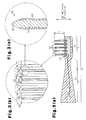
- Figs. 3(a) to 3(c) are enlarged views showing the structure of the mixed bristle bundles 70.
- each mixed bristle bundle 70 is anchored to the conductor 14 through an anchoring surface 13, which is the surface of the head 11.
- the anchoring surface 13 is a planar surface extending along a longitudinal direction of the electric toothbrush 1.
- each mixed bristle bundle 70 includes conductive bristles 30 and insulative bristles 40.
- the insulative bristles 40 are formed from a flexible insulative resin, such as polyamide resin or polybutylene terephthalate.
- each conductive bristle 30 includes a core 31.
- the core 31 is formed from a flexible conductive resin such as a carbon-containing polyamide resin or carbon-containing polybutylene terephthalate.
- the core 31 is coated by a coating 33.
- the coating 33 is formed from a flexible insulated resin, such as carbon-free polyamide resin or polybutylene terephthalate.
- the core 31 includes a distal portion 32, which projects out of a distal portion of the coating 33, and a basal portion, which projects out of a basal portion of the coating 33.
- the distal portion 32 and basal portion of the core 31 are free from the coating 33.
- the conductive bristles 30 have a height from the anchoring surface 13, or reference plane, of the head 11 that differs from that of the insulative bristles 40. More specifically, the height from the anchoring surface 13 to the distal portion of each insulative bristle 40 is greater than the height from the anchoring surface 13 to the distal portion of each conductive bristle 30. The difference in height results in a pit 34 being defined at the tip of each conductive bristle 30.
- a direction in which the conductive bristles 30 and insulative bristles 40 extend is referred to as a height-wise direction.
- the anchoring surface is not flat, hypothetical planes extending in the longitudinal direction of the electric toothbrush 1 are set along, or defined by, the anchoring surface. The surface of the head 11 opposite to the anchoring surface 13 is then set as a base plane. The hypothetical plane located at the highest position from the anchoring surface 13 is selected as the reference plane.
- the anchoring surface 13 is a planar surface extending along the longitudinal direction of the electric toothbrush 1.
- the highest position of anchoring surface 13 is the same throughout the entire anchoring surface 13. Accordingly, the anchoring surface 13 conforms to the reference plane.
- the toothpaste 80 When the toothpaste 80 includes conductive medicinal components, the current draws ions toward oral tissues. When the ions produce a sterilization effect, the ions sterilize the mouth. Cetylpyridinium chloride is one example of an electrolytic medicinal component.
- the electric toothbrush 1 of the second embodiment differs from that of the first embodiment in the structure of the head 11. Otherwise, the electric toothbrush 1 of the second embodiment has the same structure as the first embodiment. The differences will now be discussed. Like or same reference numerals are given to those components that are the same as the corresponding components of the first embodiment. Such components will not be discussed.
- the head 11 includes conductive bristle bundles 50 and insulative bristle bundles 60 to remove dental plaque.
- the conductive bristle bundles 50 and insulative bristle bundles 60 each includes a basal portion, which is anchored to the conductor 14 through the anchoring surface 13, which is a surface of the head 11.
- the conductive bristle bundles 50 and the insulative bristle bundles 60 are alternately arranged in the longitudinal direction of the head 11.
- Insulative bristle bundles 60 are arranged at distal and basal ends of the head 11 in the longitudinal direction so that the conductive bristle bundles 50 are arranged inward from the insulative bristle bundles 60.
- the anchoring surface 13 is a planar surface extending in the longitudinal direction of the electric toothbrush 1.
- each conductive bristle bundle 50 includes conductive bristles 30.
- Each conductive bristle 30 is electrically connected to the conductor 14.
- each insulative bristle bundle 60 includes insulative bristles 40.
- the height of the conductive bristle bundles 50 from the anchoring surface 13, or reference plane, of the head 11 differs from that of the insulative bristle bundles 60. More specifically, the height h from the anchoring surface 13 to a distal portion of each insulative bristle bundle 60 is greater than the height from the anchoring surface 13 to a distal portion of each conductive bristle bundle 50. The difference in height results in a pit 34 being defined at the tip of each conductive bristle bundle 50.
- the toothpaste 80 includes electrolytic medicinal components, current acts to draw the medicinal components toward oral tissues.
- the medicinal components produce a sterilization effect, the mouth is sterilized.
- the toothbrush of the second embodiment has the advantages described below.
- the electric toothbrush 1 of the third embodiment differs from that of the second embodiment in the structure of the head 11. Otherwise, the electric toothbrush 1 of the third embodiment has the same structure as the second embodiment.
- the differences will now be discussed.
- Like or same reference numerals are given to those components that are the same as the corresponding components of the first embodiment. Such components will not be discussed.
- the height h from the anchoring surface 13 to the distal portion of each insulative bristle bundle 60 is greater than that from the anchoring surface 13 to the distal portion of each conductive bristle bundle 50.
- the difference in height forms a pit 34 at the tips of the conductive bristle bundle 50.
- the insulative bristle bundles 60 are arranged at the longitudinal distal and basal ends of the head 11.
- the conductive bristle bundles 50 are arranged between the insulative bristle bundles 60.
- the conductive bristle bundles 50 are continuously anchored between the insulative bristle bundles 60 at the two ends.
- the pit 34 is formed to extend continuously at the tips of the conductive bristle bundles 50. In other words, a group of pits form the single large pit 34.
- the toothpaste 80 includes electrolytic medicinal components, current acts to draw the medicinal components toward oral tissues.
- the medicinal components produce a sterilization effect, the mouth is sterilized.
- the toothbrush of the second embodiment has the advantages described below.
- each mixed bristle bundle 70 has the same height.
- the mixed bristle bundles 70 may have different heights. More specifically, the height of the conductive bristles 30 from the reference plane and the height of the insulative bristles 40 from the reference plane may be different in each mixed bristle bundle 70.
- the height of one mixed bristle bundle 70 from the reference plane and the height of another mixed bristle bundle 70 from the reference plane may be different.
- the mixed bristle bundles arranged at the basal portion, distal portion, and middle portion of the head 11 in the longitudinal direction may be taller than the other mixed bristle bundles.
- the mixed bristle bundles arranged at the basal portion and distal portion of the head 11 may be taller than the mixed bristle bundles arranged therebetween.
- the height of the conductive bristles 30 may be the same as the height of the insulative bristles 40 in each mixed bristle bundle 70.
- the anchoring surface 13 is a planar surface extending in the longitudinal direction of the brush body 10 but may be modified as described below. Referring to Fig. 10 , the anchoring surface 13 may be curved so that the mixed bristle bundles 70 at the middle part, or peak, of the head 11 in the longitudinal direction are the tallest, and the mixed bristle bundles 70 become shorter from the middle portion toward the two ends of the brush body 10. In this case, when the basal portions of the mixed bristle bundles 70, which have the same height, are embedded with the same depth in the head 11, the height from the reference plane to the tip differs between the mixed bristle bundles 70 that are arranged adjacent to each other.
- the height of the conductive bristles 30 from the reference plane is less than the height of the insulative bristles 40 from the reference plane.
- the height of the conductive bristles 30 from the reference plane may be greater than the height of the insulative bristles 40 from the reference plane.
- pits are formed at the tips of the insulative bristles 40. Accordingly, toothpaste applied to the tips of the conductive bristles 30 is consumed before the toothpaste held in the pits of the insulative bristles 40.
- the tips of the conductive bristles 30 directly contact the gum and prevent toothpaste from interfering with the contact between the conductive bristles 30 and gum.
- the height of the conductive bristles 30 from the reference plane is less than the height of the insulative bristles 40 in each mixed bristle bundle 70.
- the conductive bristles 30 from the reference plane may be taller than the insulative bristles 40 in each mixed bristle bundle 70. This forms pits at the tips of the insulative bristles 40.
- the toothpaste 80 applied to the tips of the conductive bristles 30 is consumed before that held in the pits of the insulative bristles 40. This obtains the advantages described above.
- each conductive bristle 30 extends from the coating 33. This allows for the core 31 to enter gaps such as periodontal pockets and sterilize bacteria in a concentrated manner with chlorine. Further, the projection of the core 31 increases the energized area. This increases the electric massaging effect. Moreover, portions other than the distal portion 32 of the core 31 are covered by the coating 33, which is in insulator to supply current to the distal portion of the core 31 in a concentrated manner. This further improves the electric massaging effect.
- the height of the conductive bristle bundles 50 from the reference plane is less than the height of the insulative bristle bundles 60 from the reference plane.
- the height of the conductive bristle bundles 50 from the reference plane may be greater than the height of the insulative bristle bundles 60 from the reference plane. This case also obtains the same advantages as the modifications described above. Further, when the user applies the toothpaste 80 to the head 11 before brushing his or her teeth, the toothpaste 80 is easily received in the pits.
- the tall insulative bristle bundles 60 are arranged at the basal, distal, and middle portions of the head 11 in the longitudinal direction.
- tall conductive bristle bundles 50 may be arranged at the middle portion, and tall insulative bristle bundles 60 may be arranged at the basal and distal portions.
- tall conductive bristle bundles 50 may be arranged at the basal and distal portions, and tall insulative bristle bundles 60 may be arranged at the middle portion.
- the conductive bristles 30 have the same height, and the insulative bristles 40 have the same height. In other words, the bristles have only two levels of height. However, the bristles may have three or more levels of height.
- the conductive bristle bundles 50 anchored at the middle portion may be shorter than the other conductive bristle bundles 50. This limits the medicinal components from escaping from the conductive bristle bundles 50.
- the brush body 10 includes the head 11 and the brush stem 12.
- the brush stem 12 may be excluded from the brush body 10.
- the portion corresponding to the excluded brush stem 12 may be formed integrally with the grip 20.
- the head 11 and the grip 20 may be separate elements.
- the electric toothbrush is applied to an oscillation type electric tooth but may also be applied to a rotary type toothbrush that rotates part of a head to which bristles are anchored.
- the present invention may also be applied to a toothbrush that does not have a function for oscillating the head or a function for rotating the head.
Abstract
A brush body and toothbrush that allows for current to easily flow from conductive bristles to oral tissues or enhance ionization of electrolytic medicinal components. The brush body includes a mixed bristle bundle arranged on an anchoring surface and including a plurality of conductive bristles (50) and a plurality of insulative bristles (60). A reference plane is set on the anchoring surface (13). The conductive bristles have a height from the reference plane, and the insulative bristles have a height from the reference plane that differs from the height of the conductive bristles.
Description
- The present invention relates to a brush body, which includes conductive bristles and insulative bristles arranged on an anchoring surface, and a toothbrush including such a brush body.
- Japanese Laid-Open Patent Publication No.
2006-223369 - In the toothbrush of Japanese Laid-Open Patent Publication No.
2006-223369 - When brushing teeth using toothpaste that includes conductive medicinal components having an oral sterilization effect, electric current acts to draw the medicinal components toward the teeth surface and gum. This improves the sterilization effect of the mouth. The sterilization of the mouth, in particular, the gum prevents periodontal diseases.
- Further, when the conductive bristles directly contact oral tissues, such as the gum, during brushing, electric current flows from the conductive bristles to the gum. This produces a massaging effect and prevents inflammation of the gum.
- In the toothbrush of Japanese Laid-Open Patent Publication No.
2006-223369 - Further, when attempting to contact the gum or the like with the conductive bristles, the insulative bristles arranged near the conductive bristles first contact the gum. It is thus difficult to obtain the massaging effect when current flows from the conductive bristles to the gum or the like.
- Accordingly, it is an object of the present invention to provide a brush body and toothbrush that allows for current to easily flow from conductive bristles to oral tissues or current to easily act on electrolytic medicinal components.
- A first aspect of the present invention is a brush body including an anchoring surface. The brush body includes a mixed bristle bundle arranged on the anchoring surface. The mixed bristle bundle includes a plurality of conductive bristles and a plurality of insulative bristles. A reference plane is set on the anchoring surface. The conductive bristles have a height from the reference plane. The insulative bristles have a height from the reference plane that differs from the height of the conductive bristles.
- A second aspect of the present invention is a brush body including an anchoring surface. The brush body includes a conductive bristle bundle arranged on the anchoring surface and including a plurality of conductive bristles. An insulative bristle bundle is arranged on the anchoring surface and includes a plurality of insulative bristles. A reference plane is set on the anchoring surface. The conductive bristle bundle has a height from the reference plane. The insulative bristle bundle has a height from the reference plane that differs from the height of the conductive bristle bundle.
- A third aspect of the present invention is a brush body including an anchoring surface. The brush body includes a plurality of mixed bristle bundles arranged on the anchoring surface and includes a first mixed bristle bundle and a second mixed bristle bundle. The mixed bristle bundles each include plurality of conductive bristles and a plurality of insulative bristles. A reference plane is set on the anchoring surface. In each mixed bristle bundle, the conductive bristles have a height from the reference plane, and the insulative bristles have a height from the reference plane that differs from the height of the conductive bristles. The first mixed bristle bundle has a height from the reference plane, and the second mixed bristle bundle has a height from the reference plane that differs from the height of the first mixed bristle bundle.
- Other aspects and advantages of the present invention will become apparent from the following description, taken in conjunction with the accompanying drawings, illustrating by way of example the principles of the invention.
- The invention and preferred objects and advantages thereof, may best be understood by reference to the following description of the certain exemplifying embodiments together with the accompanying drawings in which:
-
Fig. 1 is a cross-sectional view of a toothbrush according to a first embodiment of the present invention; -
Fig. 2 is a block diagram showing the circuit configuration of the toothbrush; -
Fig. 3(a) is a cross-sectional view showing a brush body of the toothbrush,Fig. 3(b) is an enlarged view showing the distal portion of a bristle, andFig. 3(c) is an enlarged view ofFig. 3(b) ; -
Fig. 4(a) is an enlarged view showing toothpaste applied to the distal portions of the bristles before the toothpaste is consumed, andFig. 4(b) is an enlarged view showing the toothpaste applied to the distal portions of the bristles after some of the toothpaste is consumed; -
Fig. 5(a) is a cross-sectional view of a toothbrush according to a second embodiment of the present invention,Fig. 5(b) is an enlarged view showing the distal portions of conductive bristles, andFig. 5(c) is an enlarged view showing the distal portions of insulative bristles; -
Fig. 6(a) is an enlarged view showing toothpaste applied to the distal portions of the bristles before the toothpaste is consumed, andFig. 6(b) is an enlarged view showing the toothpaste applied to the distal portions of the bristles after some of the toothpaste is consumed; -
Fig. 7(a) is a cross-sectional view of a toothbrush according to a third embodiment of the present invention,Fig. 7(b) is an enlarged view showing the distal portions of conductive bristles, andFig. 7(c) is an enlarged view showing the distal portions of insulative bristles; -
Fig. 8 is a cross-sectional view of a brush body showing toothpaste applied to the distal portions of the bristles in the toothbrush of the third embodiment when the toothpaste is used; -
Fig. 9(a) is a cross-sectional view showing a brush body of a toothbrush in a modified example embodying the present invention,Fig. 9(b) is an enlarged view showing the distal portions of conductive bristles, andFig. 9(c) is an enlarged view showing the distal portions of insulative bristles; -
Fig. 10 is a cross-sectional view showing a brush body of a toothbrush in a modified example embodying the present invention. - An
electric toothbrush 1 according to a first embodiment of the present invention will now be discussed with reference toFigs. 1 to 4 . - As shown in
Fig. 1 , theelectric toothbrush 1 includes abrush body 10 and agrip 20. Thegrip 20 is grasped by a user. Thebrush body 10 is attached in a removable manner to a distal portion of thegrip 20. Anoscillation actuator 22 is retained in thegrip 20 to oscillate thebrush body 10 when brushing teeth with the electric toothbrush. - The
grip 20 is cylindrical to facilitate grasping by the user. Thegrip 20 includes agrip electrode 21,switches 26, andLEDs 27. Thegrip electrode 21 is arranged on an outer surface of thegrip 20 and contacts the user's hand when the user grasps thegrip 20. Theswitches 26 are operated by the user. TheLEDs 27 show operational states. Thegrip 20 contains abattery 24 and acircuitry 25 in addition to theoscillation actuator 22. Thebattery 24 supplies thecircuitry 25 with power. Thecircuitry 25 controls the supply of power to theoscillation actuator 22. Theoscillation actuator 22 includes anoutput shaft 23, which projects out of the distal portion of thegrip 20. Theoutput shaft 23 is inserted into thebrush body 10. - The
brush body 10 includes abrush stem 12, ahead 11, and mixedbristle bundles 70. Thebrush stem 12 is connected to thegrip 20. Thehead 11 is formed integrally with thebrush stem 12. The mixedbristle bundle 70 is anchored to thehead 11. - A
conductor 14 is arranged in thehead 11. The mixed bristlebundles 70 each include a basal portion anchored to theconductor 14. Aconnection terminal 15 and aninsertion hole 16 6 are arranged in thebrush stem 12. Theconnection terminal 15 electrically connects theconductor 14 to theoutput shaft 23 of thegrip 20. Theoutput shaft 23 is inserted into theinsertion hole 16. - With the
electric toothbrush 1, theoutput shaft 23 of thegrip 20 is fitted into theinsertion hole 16 of thebrush body 10 to attach thebrush body 10 to thegrip 20. This electrically connects theconductor 14 to thebattery 24 via theconnection terminal 15 and theoutput shaft 23. -
Fig. 2 shows the circuit configuration of theelectric toothbrush 1. - The
circuitry 25 of theelectric toothbrush 1 includes acontrol circuit 25a, acharge circuit 25b, and apower supply circuit 25c. Thecontrol circuit 25a is electrically connected to thegrip electrode 21. Thecharge circuit 25b is electrically connected to thecontrol circuit 25a. Thepower supply circuit 25c receives power from thebattery 24. Thecharge circuit 25b supplies thebattery 24 with power. - When the user uses the
electric toothbrush 1, the user and theelectric toothbrush 1 form an electric circuit. More specifically, an electric circuit is formed including thegrip electrode 21 of thegrip 20 held by the user's hand, thecontrol circuit 25a of thecircuitry 25, theoutput shaft 23 of thegrip 20, theconnection terminal 15 of thebrush body 10, theconductor 14, the mixed bristle bundles 70, oral saliva, gum tissues and the like, and the human body. When thecontrol circuit 25a applies DC voltage of a predetermined level, current flows to the above electric circuit. -
Figs. 3(a) to 3(c) are enlarged views showing the structure of the mixed bristle bundles 70. - As shown in
Fig. 3(a) , the basal portion of each mixed bristlebundle 70 is anchored to theconductor 14 through an anchoringsurface 13, which is the surface of thehead 11. The anchoringsurface 13 is a planar surface extending along a longitudinal direction of theelectric toothbrush 1. - As shown in
Fig. 3(b) , each mixed bristlebundle 70 includes conductive bristles 30 and insulative bristles 40. The insulative bristles 40 are formed from a flexible insulative resin, such as polyamide resin or polybutylene terephthalate. - As shown in
Fig. 3(c) , each conductive bristle 30 includes acore 31. Thecore 31 is formed from a flexible conductive resin such as a carbon-containing polyamide resin or carbon-containing polybutylene terephthalate. - The
core 31 is coated by acoating 33. Thecoating 33 is formed from a flexible insulated resin, such as carbon-free polyamide resin or polybutylene terephthalate. - The
core 31 includes adistal portion 32, which projects out of a distal portion of thecoating 33, and a basal portion, which projects out of a basal portion of thecoating 33. Thus, thedistal portion 32 and basal portion of the core 31 are free from thecoating 33. The basal portion of the core 31, which is exposed from thecoating 33, electrically connects the corresponding conductive bristle 30 to theconductor 14. - As shown in
Fig. 3(b) , in each mixed bristlebundle 70, the conductive bristles 30 have a height from the anchoringsurface 13, or reference plane, of thehead 11 that differs from that of the insulative bristles 40. More specifically, the height from the anchoringsurface 13 to the distal portion of each insulative bristle 40 is greater than the height from the anchoringsurface 13 to the distal portion of each conductive bristle 30. The difference in height results in apit 34 being defined at the tip of each conductive bristle 30. - Referring to
Fig. 3(a) , a direction in which the conductive bristles 30 and insulative bristles 40 extend is referred to as a height-wise direction. When the anchoring surface is not flat, hypothetical planes extending in the longitudinal direction of theelectric toothbrush 1 are set along, or defined by, the anchoring surface. The surface of thehead 11 opposite to the anchoringsurface 13 is then set as a base plane. The hypothetical plane located at the highest position from the anchoringsurface 13 is selected as the reference plane. - In the
electric toothbrush 1, the anchoringsurface 13 is a planar surface extending along the longitudinal direction of theelectric toothbrush 1. Thus, the highest position of anchoringsurface 13 is the same throughout theentire anchoring surface 13. Accordingly, the anchoringsurface 13 conforms to the reference plane. - The operation of the
electric toothbrush 1 when usingtoothpaste 80 will now be described with reference toFigs. 4(a) and 4(b) . - As shown in
Fig. 4(b) , when the user brushes his or her teeth, some of thetoothpaste 80 is consumed. Thetoothpaste 80 held inside thepits 34 is not as easily consumed as thetoothpaste 80 outside thepits 34, on the tips of the insulative bristles 40. Thus, in a state in which thetoothpaste 80 on the tips of the insulative bristles 40 is being consumed, current acts on thetoothpaste 80 in thepits 34 when energized. - When the
toothpaste 80 includes conductive medicinal components, the current draws ions toward oral tissues. When the ions produce a sterilization effect, the ions sterilize the mouth. Cetylpyridinium chloride is one example of an electrolytic medicinal component. - (1) In the
electric toothbrush 1, the height of the conductive bristles 30 from the reference plane is less than the height of the insulative bristles 40 from the reference plane. This forms thepits 34 that hold the toothpaste on the distal portion of the conductive bristles 30.
As a result, when brushing the teeth, thetoothpaste 80 held inside thepits 34 is not as easily consumed as thetoothpaste 80 held outside thepits 34. Thus, current easily acts on thetoothpaste 80 in thepits 34 when energized. Further, medicinal components are held in thepits 34. This suppresses dispersion of the medicinal components throughout the mouth. Moreover, current acts to supply the necessary portions, such as the gum, with the medicinal components in a concentrated manner. - (2) The
electric toothbrush 1 includes the conductive bristles 30. The core 31 projects out of thecoating 33 in each conductive bristle 30. The projection of the core 31 increases the energized area. Thus, current efficiently acts on the medicinal components. Further, thecore 31, excluding thedistal portion 32, is coated by thecoating 33, which is insulative. This supplies current in a concentrated manner to the distal portion of thecore 31. Thus, current further efficiently acts on the medicinal components. - An
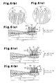
electric toothbrush 1 according to a second embodiment of the present invention will now be discussed with reference toFigs. 5 and 6 . - The
electric toothbrush 1 of the second embodiment differs from that of the first embodiment in the structure of thehead 11. Otherwise, theelectric toothbrush 1 of the second embodiment has the same structure as the first embodiment. The differences will now be discussed. Like or same reference numerals are given to those components that are the same as the corresponding components of the first embodiment. Such components will not be discussed. - As shown in
Fig. 5(a) , thehead 11 includes conductive bristle bundles 50 and insulative bristlebundles 60 to remove dental plaque. The conductive bristle bundles 50 and insulative bristlebundles 60 each includes a basal portion, which is anchored to theconductor 14 through the anchoringsurface 13, which is a surface of thehead 11. The conductive bristle bundles 50 and the insulative bristlebundles 60 are alternately arranged in the longitudinal direction of thehead 11. Insulative bristle bundles 60 are arranged at distal and basal ends of thehead 11 in the longitudinal direction so that the conductive bristle bundles 50 are arranged inward from the insulative bristle bundles 60. The anchoringsurface 13 is a planar surface extending in the longitudinal direction of theelectric toothbrush 1. - As shown in
Fig. 5(b) , each conductive bristlebundle 50 includes conductive bristles 30. Each conductive bristle 30 is electrically connected to theconductor 14. - As shown in
Fig. 5(c) , each insulative bristlebundle 60 includes insulative bristles 40. - As shown in
Fig. 5(a) , the height of the conductive bristle bundles 50 from the anchoringsurface 13, or reference plane, of thehead 11 differs from that of the insulative bristle bundles 60. More specifically, the height h from the anchoringsurface 13 to a distal portion of each insulative bristlebundle 60 is greater than the height from the anchoringsurface 13 to a distal portion of each conductive bristlebundle 50. The difference in height results in apit 34 being defined at the tip of each conductive bristlebundle 50. - The operation of the
electric toothbrush 1 when usingtoothpaste 80 will now be described with reference toFigs. 6(a) and 6(b) . As shown inFig. 6(a) , before starting tooth brushing, when the user appliestoothpaste 80 to the distal portions of the conductive bristle bundles 50 and the insulative bristlebundles 60, some of thetoothpaste 80 is received in thepits 34. - As shown in
Fig. 6(b) , when the user brushes his or her teeth, some of thetoothpaste 80 is consumed. Thetoothpaste 80 held inside thepits 34 is not as easily consumed as thetoothpaste 80 outside thepits 34, or the toothpaste on the tips of the insulative bristle bundles 60. Thus, in a state in which thetoothpaste 80 on the distal portions of the insulative bristle bundles 60 is being consumed, current acts on thetoothpaste 80 in thepits 34 when energized. - When the
toothpaste 80 includes electrolytic medicinal components, current acts to draw the medicinal components toward oral tissues. When the medicinal components produce a sterilization effect, the mouth is sterilized. - In addition to advantages (1) and (2) of the first embodiment, the toothbrush of the second embodiment has the advantages described below.
- (3) The
pits 34 of theelectric toothbrush 1 in the second embodiment are larger than thepits 34 of theelectric toothbrush 1 in the first embodiment. This allows for current to act onmore toothpaste 80 during brushing. Further, when the user applies thetoothpaste 80 to thehead 11 before brushing his or her teeth, thetoothpaste 80 can easily enter thepits 34 at the tips of the conductive bristle bundles 50 without remaining on the tips of the insulative bristle bundles 60. - (4) In the
electric toothbrush 1, the insulative bristlebundles 60 are taller than the conductive bristle bundles 50. Thus, the tips of the insulative bristlebundles 60 easily enter periodontal pockets during tooth brushing. Thus, in comparison to when the conductive bristle bundles 50 are taller than the insulative bristlebundles 60, the effect for removing bacteria from the periodontal pockets is increased. - (5) Insulative bristle bundles 60 are arranged at the longitudinal distal and basal ends of the
head 11 so that the conductive bristle bundles 50 are arranged inward from the insulative bristle bundles 60. Thus, the insulative bristlebundles 60 easily enter periodontal pockets during tooth brushing. This increases the effect for removing bacteria from the periodontal pockets. - An
electric toothbrush 1 according to a third embodiment of the present invention will now be discussed with reference toFigs. 7 and 8 . - The
electric toothbrush 1 of the third embodiment differs from that of the second embodiment in the structure of thehead 11. Otherwise, theelectric toothbrush 1 of the third embodiment has the same structure as the second embodiment. The differences will now be discussed. Like or same reference numerals are given to those components that are the same as the corresponding components of the first embodiment. Such components will not be discussed. - As shown in
Fig. 7(a) , the height h from the anchoringsurface 13 to the distal portion of each insulative bristlebundle 60 is greater than that from the anchoringsurface 13 to the distal portion of each conductive bristlebundle 50. The difference in height forms apit 34 at the tips of the conductive bristlebundle 50. - The insulative bristle
bundles 60 are arranged at the longitudinal distal and basal ends of thehead 11. The conductive bristle bundles 50 are arranged between the insulative bristle bundles 60. The conductive bristle bundles 50 are continuously anchored between the insulative bristlebundles 60 at the two ends. Thus, thepit 34 is formed to extend continuously at the tips of the conductive bristle bundles 50. In other words, a group of pits form the singlelarge pit 34. - The operation of the
electric toothbrush 1 when usingtoothpaste 80 will now be described with reference toFig. 8 . Before starting tooth brushing, when the user appliestoothpaste 80 to the distal portions of the conductive bristle bundles 50 and the insulative bristlebundles 60, some of thetoothpaste 80 is received in thepit 34. - As shown in
Fig. 8 , when the user brushes his or her teeth, some of thetoothpaste 80 is consumed. Thetoothpaste 80 held inside thepit 34 is not as easily consumed as thetoothpaste 80 outside thepit 34, or the toothpaste on the tips of the insulative bristle bundles 60. Thus, in a state in which thetoothpaste 80 on the distal portions of the insulative bristle bundles 60 is being consumed, thetoothpaste 80 in thepit 34 is ionized when energized. - When the
toothpaste 80 includes electrolytic medicinal components, current acts to draw the medicinal components toward oral tissues. When the medicinal components produce a sterilization effect, the mouth is sterilized. - In addition to advantages (3) and (5) of the second embodiment, the toothbrush of the second embodiment has the advantages described below.
- (6) The pit formed on the tip of each conductive bristle
bundle 50 forms thesingle pit 34. This allows for current to act on a large amount of thetoothpaste 80 during tooth brushing. Further, when the user applies thetoothpaste 80 to thehead 11, the application of thetoothpaste 80 to thepit 34 is further facilitated. - It should be apparent to those skilled in the art that the present invention may be embodied in many other specific forms without departing from the spirit or scope of the invention. Particularly, it should be understood that the present invention may be embodied in the following forms.
- In the first embodiment, each mixed bristle
bundle 70 has the same height. Instead, the mixed bristle bundles 70 may have different heights. More specifically, the height of the conductive bristles 30 from the reference plane and the height of the insulative bristles 40 from the reference plane may be different in each mixed bristlebundle 70. At the same time, the height of one mixed bristlebundle 70 from the reference plane and the height of another mixed bristlebundle 70 from the reference plane may be different. In this case, for example, referring toFig. 5(a) , the mixed bristle bundles arranged at the basal portion, distal portion, and middle portion of thehead 11 in the longitudinal direction may be taller than the other mixed bristle bundles. Alternatively, referring toFig. 7(a) , the mixed bristle bundles arranged at the basal portion and distal portion of thehead 11 may be taller than the mixed bristle bundles arranged therebetween. - When the height of one mixed bristle
bundle 70 from the reference plane and the height of another mixed bristlebundle 70 are different as described in the above modification, the height of the conductive bristles 30 may be the same as the height of the insulative bristles 40 in each mixed bristlebundle 70. - In the first embodiment, the anchoring
surface 13 is a planar surface extending in the longitudinal direction of thebrush body 10 but may be modified as described below. Referring toFig. 10 , the anchoringsurface 13 may be curved so that the mixed bristle bundles 70 at the middle part, or peak, of thehead 11 in the longitudinal direction are the tallest, and the mixed bristle bundles 70 become shorter from the middle portion toward the two ends of thebrush body 10. In this case, when the basal portions of the mixed bristle bundles 70, which have the same height, are embedded with the same depth in thehead 11, the height from the reference plane to the tip differs between the mixed bristle bundles 70 that are arranged adjacent to each other. In this modification, when the surface of thehead 11 opposite to the anchoringsurface 13 is set as a base plane for measuring height, a hypothetical plane (plane indicated by broken line inFig. 10 ) lying on the peak of the anchoringsurface 13 is set as a reference plane. - In the first embodiment, the height of the conductive bristles 30 from the reference plane is less than the height of the insulative bristles 40 from the reference plane. However, the height of the conductive bristles 30 from the reference plane may be greater than the height of the insulative bristles 40 from the reference plane. In this case, pits are formed at the tips of the insulative bristles 40. Accordingly, toothpaste applied to the tips of the conductive bristles 30 is consumed before the toothpaste held in the pits of the insulative bristles 40. Thus, the tips of the conductive bristles 30 directly contact the gum and prevent toothpaste from interfering with the contact between the
conductive bristles 30 and gum. This has an effect for warming the gum when current flows and produces an electric massaging effect that prevents inflammation of the gum. In this case, when the toothpaste contains components such as an endothermic or exothermic agent, an endothermic effect or exothermic effect further improves the electric massaging effect. - In the first embodiment, the height of the conductive bristles 30 from the reference plane is less than the height of the insulative bristles 40 in each mixed bristle
bundle 70. However, the conductive bristles 30 from the reference plane may be taller than the insulative bristles 40 in each mixed bristlebundle 70. This forms pits at the tips of the insulative bristles 40. In this case, thetoothpaste 80 applied to the tips of the conductive bristles 30 is consumed before that held in the pits of the insulative bristles 40. This obtains the advantages described above. - Further, the
core 31 of each conductive bristle 30 extends from thecoating 33. This allows for the core 31 to enter gaps such as periodontal pockets and sterilize bacteria in a concentrated manner with chlorine. Further, the projection of the core 31 increases the energized area. This increases the electric massaging effect. Moreover, portions other than thedistal portion 32 of the core 31 are covered by thecoating 33, which is in insulator to supply current to the distal portion of the core 31 in a concentrated manner. This further improves the electric massaging effect. - In the second and third embodiments, the height of the conductive bristle bundles 50 from the reference plane is less than the height of the insulative bristle
bundles 60 from the reference plane. However, the height of the conductive bristle bundles 50 from the reference plane may be greater than the height of the insulative bristlebundles 60 from the reference plane. This case also obtains the same advantages as the modifications described above. Further, when the user applies thetoothpaste 80 to thehead 11 before brushing his or her teeth, thetoothpaste 80 is easily received in the pits. - In the second embodiment, the tall insulative bristle
bundles 60 are arranged at the basal, distal, and middle portions of thehead 11 in the longitudinal direction. However, for example, tall conductive bristle bundles 50 may be arranged at the middle portion, and tall insulative bristlebundles 60 may be arranged at the basal and distal portions. Alternatively, tall conductive bristle bundles 50 may be arranged at the basal and distal portions, and tall insulative bristlebundles 60 may be arranged at the middle portion. - In each embodiment, the conductive bristles 30 have the same height, and the insulative bristles 40 have the same height. In other words, the bristles have only two levels of height. However, the bristles may have three or more levels of height. For example, as shown in
Fig. 9(a) , the conductive bristle bundles 50 anchored at the middle portion may be shorter than the other conductive bristle bundles 50. This limits the medicinal components from escaping from the conductive bristle bundles 50. - In each embodiment, the
brush body 10 includes thehead 11 and thebrush stem 12. However, thebrush stem 12 may be excluded from thebrush body 10. In this case, the portion corresponding to the excludedbrush stem 12 may be formed integrally with thegrip 20. Alternatively, thehead 11 and thegrip 20 may be separate elements. - In each embodiment, the electric toothbrush is applied to an oscillation type electric tooth but may also be applied to a rotary type toothbrush that rotates part of a head to which bristles are anchored. The present invention may also be applied to a toothbrush that does not have a function for oscillating the head or a function for rotating the head.
- The present examples and embodiments are to be considered as illustrative and not restrictive.
Claims (7)
- A brush body including an anchoring surface, the brush body characterized by a mixed bristle bundle arranged on the anchoring surface, wherein
the mixed bristle bundle includes a plurality of conductive bristles and a plurality of insulative bristles,
a reference plane is set on the anchoring surface,
the conductive bristles have a height from the reference plane, and
the insulative bristles have a height from the reference plane that differs from the height of the conductive bristles. - A brush body including an anchoring surface, the brush body characterized by:a conductive bristle bundle arranged on the anchoring surface and including a plurality of conductive bristles; andan insulative bristle bundle arranged on the anchoring surface and including a plurality of insulative bristles;wherein a reference plane is set on the anchoring surface, the conductive bristle bundle has a height from the reference plane, and the insulative bristle bundle has a height from the reference plane that differs from the height of the conductive bristle bundle.
- A brush body including an anchoring surface, the brush body characterized by:a plurality of mixed bristle bundles arranged on the anchoring surface and including a first mixed bristle bundle and a second mixed bristle bundle, wherein the mixed bristle bundles each include plurality of conductive bristles and a plurality of insulative bristles; andwherein a reference plane is set on the anchoring surface;in each mixed bristle bundle, the conductive bristles have a height from the reference plane, and the insulative bristles have a height from the reference plane that differs from the height of the conductive bristles; andthe first mixed bristle bundle has a height from the reference plane, and the second mixed bristle bundle has a height from the reference plane that differs from the height of the first mixed bristle bundle.
- The brush body according to any one of claims 1 to 3, characterized in that each of the conductive bristles includes a conductive core, which has a tip, and a coating, which covers the core excluding at least the tip.
- The brush body according to any one of claims 1 to 3, characterized in that the height of the insulative bristles from the reference plane is less than the height of the conductive bristles from the reference plane, and the insulative bristles each include a tip at which a pit is formed to receive toothpaste.
- The brush body according to any one of claims 1 to 3, characterized in that the height of the conductive bristles from the reference plane is less than the height of the insulative bristles from the reference plane, and the conductive bristles each include a tip at which a pit is formed to receive toothpaste.
- A toothbrush characterized by the brush body according to any one of claims 1 to 3.
Applications Claiming Priority (1)
| Application Number | Priority Date | Filing Date | Title |
|---|---|---|---|
| JP2010071142A JP5292346B2 (en) | 2010-03-25 | 2010-03-25 | Brush body and toothbrush |
Publications (1)
| Publication Number | Publication Date |
|---|---|
| EP2368457A2 true EP2368457A2 (en) | 2011-09-28 |
Family
ID=44246423
Family Applications (1)
| Application Number | Title | Priority Date | Filing Date |
|---|---|---|---|
| EP11159518A Withdrawn EP2368457A2 (en) | 2010-03-25 | 2011-03-24 | Brush body and toothbrush |
Country Status (4)
| Country | Link |
|---|---|
| US (1) | US20110232014A1 (en) |
| EP (1) | EP2368457A2 (en) |
| JP (1) | JP5292346B2 (en) |
| CN (1) | CN102197919A (en) |
Families Citing this family (12)
| Publication number | Priority date | Publication date | Assignee | Title |
|---|---|---|---|---|
| ES2593132T3 (en) | 2011-07-06 | 2016-12-05 | Braun Gmbh | Cleaning section for an electric oral hygiene device |
| US9009901B2 (en) * | 2011-09-20 | 2015-04-21 | Braun Gmbh | Oral care devices having automatic mode selection |
| JP2013118895A (en) * | 2011-12-06 | 2013-06-17 | Lion Corp | Oral ion brush |
| US10299580B2 (en) | 2013-12-12 | 2019-05-28 | Colgate-Palmolive Company | Multi-component bristle having components with different oral care additives, and oral care implement comprising the same |
| US10477958B2 (en) | 2013-12-12 | 2019-11-19 | Colgate-Palmolive Company | Multi-component bristle having components with different oral care additives, and oral care implement comprising the same |
| CN105792701B (en) | 2013-12-12 | 2018-03-02 | 高露洁-棕榄公司 | Spiral bristle with the strand part with different oral care additives and the oral care implement for including the spiral bristle |
| US10702057B2 (en) | 2015-07-07 | 2020-07-07 | Colgate-Palmolive Company | Oral care implement and monofilament bristle for use with the same |
| CN106901859A (en) * | 2017-03-07 | 2017-06-30 | 成都米士科技有限公司 | Electron ion apparatus for cleaning oral cavity |
| CN108742916A (en) * | 2018-06-25 | 2018-11-06 | 深圳市港桐鑫光电科技有限公司 | A kind of electric toothbrush based on LED light nursing |
| CN110292454A (en) * | 2019-08-06 | 2019-10-01 | 深圳市欣点通科技有限公司 | A kind of multifunctional electric toothbrush |
| CN112336489A (en) * | 2020-11-11 | 2021-02-09 | 慈溪赛嘉电子有限公司 | Electric toothbrush device |
| CN112370199B (en) * | 2020-11-11 | 2022-03-18 | 慈溪赛嘉电子有限公司 | Electric toothbrush device |
Citations (1)
| Publication number | Priority date | Publication date | Assignee | Title |
|---|---|---|---|---|
| JP2006223369A (en) | 2005-02-15 | 2006-08-31 | Matsushita Electric Works Ltd | Electronic toothbrush |
Family Cites Families (12)
| Publication number | Priority date | Publication date | Assignee | Title |
|---|---|---|---|---|
| US2100138A (en) * | 1933-11-24 | 1937-11-23 | Heldt Friedrich | Bristle for cleaning devices |
| US4361922A (en) * | 1981-01-06 | 1982-12-07 | Schlegel Corporation | Cleaning brush for electrostatic copiers, printers and the like |
| JPH01181804A (en) * | 1988-01-14 | 1989-07-19 | Kaken Pharmaceut Co Ltd | Tooth brush |
| JPH06209824A (en) * | 1992-04-22 | 1994-08-02 | Achilles Corp | Conductive fiber product and its production |
| DE19605845A1 (en) * | 1996-02-16 | 1997-08-21 | Lingner & Fischer Gmbh | Device and method for the detection of dental plaque |
| JP3909446B2 (en) * | 1996-10-25 | 2007-04-25 | 生田 稔郎 | Magnetic ion toothbrush |
| JPH10192055A (en) * | 1997-01-06 | 1998-07-28 | Kitano Seisaku Kk | Motor-driven tooth brush |
| US5815872A (en) * | 1997-08-08 | 1998-10-06 | Optiva Corporation | Pressure overload indicator system for power toothbrushes |
| US6029303A (en) * | 1998-03-04 | 2000-02-29 | Dewan; Raman N. | Electronic toothbrush |
| US6029304A (en) * | 1998-06-09 | 2000-02-29 | Colgate-Palmolive Company | Light interactive toothbrush |
| JP2003066669A (en) * | 2001-08-27 | 2003-03-05 | Tsuchiya Tsco Co Ltd | Conductive brush |
| JP4627036B2 (en) * | 2005-12-28 | 2011-02-09 | 花王株式会社 | Thermal brush |
-
2010
- 2010-03-25 JP JP2010071142A patent/JP5292346B2/en not_active Expired - Fee Related
-
2011
- 2011-03-24 EP EP11159518A patent/EP2368457A2/en not_active Withdrawn
- 2011-03-25 CN CN2011100815530A patent/CN102197919A/en active Pending
- 2011-03-25 US US13/071,808 patent/US20110232014A1/en not_active Abandoned
Patent Citations (1)
| Publication number | Priority date | Publication date | Assignee | Title |
|---|---|---|---|---|
| JP2006223369A (en) | 2005-02-15 | 2006-08-31 | Matsushita Electric Works Ltd | Electronic toothbrush |
Also Published As
| Publication number | Publication date |
|---|---|
| JP5292346B2 (en) | 2013-09-18 |
| CN102197919A (en) | 2011-09-28 |
| JP2011200466A (en) | 2011-10-13 |
| US20110232014A1 (en) | 2011-09-29 |
Similar Documents
| Publication | Publication Date | Title |
|---|---|---|
| EP2368457A2 (en) | Brush body and toothbrush | |
| EP2517601A1 (en) | Brush body and toothbrush | |
| EP2394530B1 (en) | Brush body, method of its manufacture and toothbrush including this brush body | |
| EP2517602A1 (en) | Brush body and toothbrush | |
| US6743015B2 (en) | Iontophoretic apparatus | |
| US20130180061A1 (en) | Head Portion And Handle Portion Of An Oral Care Device | |
| JP7282395B2 (en) | Plasma treatment device | |
| EP1908435B1 (en) | Mouth cleaning device | |
| JP2013525074A (en) | Tongue cleaning device | |
| JP2010124904A (en) | Oral cavity care instrument | |
| US20190380482A1 (en) | Oral care device and attachment | |
| CN103987295B (en) | Ion brush is used in oral cavity | |
| WO2011013533A1 (en) | Gum massage brush and gum massage device | |
| JP2003250636A (en) | Toothbrush and hairbrush | |
| JP2012000149A (en) | Energized brush for gum massage | |
| JP4372537B2 (en) | Oral cleaning tool | |
| JPH05305010A (en) | Ion toothbrush | |
| JP2013066547A (en) | Oral care device | |
| JP2012000150A (en) | Brush body and toothbrush including the same | |
| WO2006104463A1 (en) | Toothbrush | |
| JP3036521U (en) | toothbrush | |
| JPH0751097B2 (en) | Electronic interdental brush |
Legal Events
| Date | Code | Title | Description |
|---|---|---|---|
| PUAI | Public reference made under article 153(3) epc to a published international application that has entered the european phase |
Free format text: ORIGINAL CODE: 0009012 |
|
| 17P | Request for examination filed |
Effective date: 20110324 |
|
| AK | Designated contracting states |
Kind code of ref document: A2 Designated state(s): AL AT BE BG CH CY CZ DE DK EE ES FI FR GB GR HR HU IE IS IT LI LT LU LV MC MK MT NL NO PL PT RO RS SE SI SK SM TR |
|
| AX | Request for extension of the european patent |
Extension state: BA ME |
|
| RAP1 | Party data changed (applicant data changed or rights of an application transferred) |
Owner name: PANASONIC CORPORATION |
|
| STAA | Information on the status of an ep patent application or granted ep patent |
Free format text: STATUS: THE APPLICATION HAS BEEN WITHDRAWN |
|
| 18W | Application withdrawn |
Effective date: 20140604 |