EP1908419B1 - Dispositif de verrouillage pour un dispositif pour l'anastomose - Google Patents
Dispositif de verrouillage pour un dispositif pour l'anastomose Download PDFInfo
- Publication number
- EP1908419B1 EP1908419B1 EP06021056A EP06021056A EP1908419B1 EP 1908419 B1 EP1908419 B1 EP 1908419B1 EP 06021056 A EP06021056 A EP 06021056A EP 06021056 A EP06021056 A EP 06021056A EP 1908419 B1 EP1908419 B1 EP 1908419B1
- Authority
- EP
- European Patent Office
- Prior art keywords
- ring
- proximal
- locking
- locking device
- distal
- Prior art date
- Legal status (The legal status is an assumption and is not a legal conclusion. Google has not performed a legal analysis and makes no representation as to the accuracy of the status listed.)
- Active
Links
- 241001417534 Lutjanidae Species 0.000 claims description 32
- 230000003872 anastomosis Effects 0.000 claims description 21
- 210000002105 tongue Anatomy 0.000 claims description 8
- 230000002452 interceptive effect Effects 0.000 claims description 5
- 210000001519 tissue Anatomy 0.000 description 30
- 238000000034 method Methods 0.000 description 12
- 210000002784 stomach Anatomy 0.000 description 11
- 230000006835 compression Effects 0.000 description 9
- 238000007906 compression Methods 0.000 description 9
- 230000007246 mechanism Effects 0.000 description 8
- 238000001356 surgical procedure Methods 0.000 description 8
- 230000002496 gastric effect Effects 0.000 description 7
- 210000000813 small intestine Anatomy 0.000 description 7
- 208000008589 Obesity Diseases 0.000 description 6
- 238000013459 approach Methods 0.000 description 5
- 208000012696 congenital leptin deficiency Diseases 0.000 description 5
- 208000001022 morbid obesity Diseases 0.000 description 5
- 230000008901 benefit Effects 0.000 description 4
- 239000012530 fluid Substances 0.000 description 4
- 238000003780 insertion Methods 0.000 description 3
- 230000037431 insertion Effects 0.000 description 3
- 210000001953 common bile duct Anatomy 0.000 description 2
- 230000008878 coupling Effects 0.000 description 2
- 238000010168 coupling process Methods 0.000 description 2
- 238000005859 coupling reaction Methods 0.000 description 2
- 230000001419 dependent effect Effects 0.000 description 2
- 210000003238 esophagus Anatomy 0.000 description 2
- 230000037406 food intake Effects 0.000 description 2
- 235000012631 food intake Nutrition 0.000 description 2
- 210000001035 gastrointestinal tract Anatomy 0.000 description 2
- 210000000936 intestine Anatomy 0.000 description 2
- 238000002350 laparotomy Methods 0.000 description 2
- 230000004048 modification Effects 0.000 description 2
- 238000012986 modification Methods 0.000 description 2
- 210000000056 organ Anatomy 0.000 description 2
- 230000002792 vascular Effects 0.000 description 2
- 208000019693 Lung disease Diseases 0.000 description 1
- 206010025476 Malabsorption Diseases 0.000 description 1
- 208000004155 Malabsorption Syndromes Diseases 0.000 description 1
- 206010061902 Pancreatic neoplasm Diseases 0.000 description 1
- 208000006011 Stroke Diseases 0.000 description 1
- 206010052428 Wound Diseases 0.000 description 1
- 208000027418 Wounds and injury Diseases 0.000 description 1
- 238000007681 bariatric surgery Methods 0.000 description 1
- 210000000941 bile Anatomy 0.000 description 1
- 210000000013 bile duct Anatomy 0.000 description 1
- 230000015572 biosynthetic process Effects 0.000 description 1
- 238000009223 counseling Methods 0.000 description 1
- 206010012601 diabetes mellitus Diseases 0.000 description 1
- 235000005911 diet Nutrition 0.000 description 1
- 230000000378 dietary effect Effects 0.000 description 1
- 210000001198 duodenum Anatomy 0.000 description 1
- 230000000694 effects Effects 0.000 description 1
- 208000019622 heart disease Diseases 0.000 description 1
- 238000005286 illumination Methods 0.000 description 1
- 238000003384 imaging method Methods 0.000 description 1
- 238000002513 implantation Methods 0.000 description 1
- 208000015181 infectious disease Diseases 0.000 description 1
- 238000002347 injection Methods 0.000 description 1
- 239000007924 injection Substances 0.000 description 1
- 230000007794 irritation Effects 0.000 description 1
- 238000007629 laparoscopic insertion Methods 0.000 description 1
- 230000007774 longterm Effects 0.000 description 1
- 208000015486 malignant pancreatic neoplasm Diseases 0.000 description 1
- 239000002184 metal Substances 0.000 description 1
- 235000020824 obesity Nutrition 0.000 description 1
- 201000002528 pancreatic cancer Diseases 0.000 description 1
- 208000008443 pancreatic carcinoma Diseases 0.000 description 1
- 230000000144 pharmacologic effect Effects 0.000 description 1
- 229920000642 polymer Polymers 0.000 description 1
- 230000008569 process Effects 0.000 description 1
- 230000004044 response Effects 0.000 description 1
- 230000036186 satiety Effects 0.000 description 1
- 235000019627 satiety Nutrition 0.000 description 1
- 239000000243 solution Substances 0.000 description 1
- 210000001562 sternum Anatomy 0.000 description 1
- 238000002560 therapeutic procedure Methods 0.000 description 1
Images


Classifications
-
- A—HUMAN NECESSITIES
- A61—MEDICAL OR VETERINARY SCIENCE; HYGIENE
- A61B—DIAGNOSIS; SURGERY; IDENTIFICATION
- A61B17/00—Surgical instruments, devices or methods
- A61B17/11—Surgical instruments, devices or methods for performing anastomosis; Buttons for anastomosis
- A61B17/1114—Surgical instruments, devices or methods for performing anastomosis; Buttons for anastomosis of the digestive tract, e.g. bowels or oesophagus
-
- A—HUMAN NECESSITIES
- A61—MEDICAL OR VETERINARY SCIENCE; HYGIENE
- A61B—DIAGNOSIS; SURGERY; IDENTIFICATION
- A61B17/00—Surgical instruments, devices or methods
- A61B2017/00477—Coupling
-
- A—HUMAN NECESSITIES
- A61—MEDICAL OR VETERINARY SCIENCE; HYGIENE
- A61B—DIAGNOSIS; SURGERY; IDENTIFICATION
- A61B17/00—Surgical instruments, devices or methods
- A61B17/0057—Implements for plugging an opening in the wall of a hollow or tubular organ, e.g. for sealing a vessel puncture or closing a cardiac septal defect
- A61B2017/00575—Implements for plugging an opening in the wall of a hollow or tubular organ, e.g. for sealing a vessel puncture or closing a cardiac septal defect for closure at remote site, e.g. closing atrial septum defects
- A61B2017/00606—Implements H-shaped in cross-section, i.e. with occluders on both sides of the opening
-
- A—HUMAN NECESSITIES
- A61—MEDICAL OR VETERINARY SCIENCE; HYGIENE
- A61B—DIAGNOSIS; SURGERY; IDENTIFICATION
- A61B17/00—Surgical instruments, devices or methods
- A61B17/0057—Implements for plugging an opening in the wall of a hollow or tubular organ, e.g. for sealing a vessel puncture or closing a cardiac septal defect
- A61B2017/00575—Implements for plugging an opening in the wall of a hollow or tubular organ, e.g. for sealing a vessel puncture or closing a cardiac septal defect for closure at remote site, e.g. closing atrial septum defects
- A61B2017/00619—Locking means for locking the implement in expanded state
-
- A—HUMAN NECESSITIES
- A61—MEDICAL OR VETERINARY SCIENCE; HYGIENE
- A61B—DIAGNOSIS; SURGERY; IDENTIFICATION
- A61B17/00—Surgical instruments, devices or methods
- A61B17/0057—Implements for plugging an opening in the wall of a hollow or tubular organ, e.g. for sealing a vessel puncture or closing a cardiac septal defect
- A61B2017/00575—Implements for plugging an opening in the wall of a hollow or tubular organ, e.g. for sealing a vessel puncture or closing a cardiac septal defect for closure at remote site, e.g. closing atrial septum defects
- A61B2017/00623—Introducing or retrieving devices therefor
-
- A—HUMAN NECESSITIES
- A61—MEDICAL OR VETERINARY SCIENCE; HYGIENE
- A61B—DIAGNOSIS; SURGERY; IDENTIFICATION
- A61B17/00—Surgical instruments, devices or methods
- A61B2017/00982—General structural features
- A61B2017/00986—Malecots, e.g. slotted tubes, of which the distal end is pulled to deflect side struts
-
- A—HUMAN NECESSITIES
- A61—MEDICAL OR VETERINARY SCIENCE; HYGIENE
- A61B—DIAGNOSIS; SURGERY; IDENTIFICATION
- A61B17/00—Surgical instruments, devices or methods
- A61B17/11—Surgical instruments, devices or methods for performing anastomosis; Buttons for anastomosis
- A61B2017/1139—Side-to-side connections, e.g. shunt or X-connections
Definitions
- the present invention relates, in general, to devices and methods for surgically modifying organs and vessels.
- anastomosis devices for joining two organs such as, for example, two separate lengths of small bowel to each other, a section of small bowel to the stomach, or the common bile duct to the duodenum in a procedure called a choledochoduodenostomy.
- Vascular anastomosis may be performed as well.
- morbid obesity The percentage of the world population suffering from morbid obesity is steadily increasing. Severely obese persons are susceptible to increased risk of heart disease, stroke, diabetes, pulmonary disease, and accidents. Because of the effect of morbid obesity to the life of the patient, methods of treating morbid obesity are being researched.
- Surgical treatments of morbid obesity have been increasingly used with greater success. These approaches may be generalized as those that reduce the effective size of the stomach, limiting the amount of food intake, and those that create malabsorption of the food that is eaten. For instance, some patients benefit from adjustable gastric bands (AGB) that are laparoscopically placed about the stomach to form a stoma of a desired size that allows food to fill an upper portion of the stomach, causing a feeling of satiety.
- AGB adjustable gastric bands
- a fluid conduit communicates between an inwardly presented fluid bladder of the AGB to a fluid injection port subcutaneously placed in front of the patient's sternum. A syringe needle may then inject or withdraw fluid as desired to adjust the AGB.
- a method for gastric bypass surgery includes the insertion of proximal and distal anastomosis members (e.g., anvils) transorally with grasping forceps.
- the stomach and the small intestine are transected endoscopically by a surgical severing and stapling instrument to create a gastric pouch, a drainage loop, and a Roux limb.
- An endoscopically inserted circular stapler attaches to the distal anastomosis member to join the drainage loop to a distal portion of the intestine, and the circular stapler attaches to the proximal anastomosis member to join the Roux limb to the gastric pouch.
- anastomosis member is removed to create an orifice between joined portions of the stomach and intestine.
- This method reduces the number of laparoscopic ports, avoids a laparoscopic insertion of an anastomosis instrument (e.g., circular stapler) into an enlarged surgical port, and eliminates the need for an enterotomy and an enterotomy closure.
- an anastomosis instrument e.g., circular stapler
- the ring device further has proximal arms that are attached to the proximal ring and distal arms that are attached to the distal ring. Inwardly directed ends of the distal arms are coupled to inwardly directed ends of the proximal arms at a center ring such that the arms will outwardly actuate when the rings are drawn closer together during actuation of the applier.
- a latching mechanism comprises a hook protruding from the distal ring proximally such that it snap engages the proximal ring when the ring device assumes its actuated shape of a rivet.
- the applier comprises radially protruding catches which engage the ring such that the spacing of the distal ring to the center ring and the spacing of the proximal ring to the center ring may be reduced by a translational movement of the catches.
- proximal to each catch is a release ramp that causes the catch to move inwardly as the release ramp contacts the next more proximal ring at full actuation.
- the anastomotic ring device and applier disclosed in US 2005/0070926 A1 and US 2005/0070935 make it possible to perform a single lumen access anastomosis through existing trocar ports and to create an anastomotic attachment between lumens obviating the need for surgical stapling and suturing.
- this known devices have the disadvantage that the latching mechanism of the ring device locks the rings automatically when they reach their fully actuated configuration and this locking occurs at only one set configuration, i.e. ring distance, of the ring device.
- the ring device can be deployed and actuated with only one preset ring distance, without any possibility of ring distance adjustment.
- different ring devices must be provided for different tissue thicknesses or different tissue compression rates and an adjustment of the tissue compression during deployment (i.e. adjustment of the distance between the distal and proximal rings) of the ring device is impossible.
- the automatic latching of the ring device might disturb the ring approximation and the correct positioning of the tissue walls between the rings during deployment and actuation of the anastomotic device.
- the object of the present invention is therefore to improve the known anastomotic ring device such that an adjustment of the ring compression or ring approximation (i.e. tissue thickness) becomes possible.
- an anastomosis device comprises:
- the locking device can be adjusted to different distances between the distal and proximal rings, allowing the ring device to be deployed at different ring distances and different tissue pressures. Moreover, by providing a locking device separate from the ring device, the latter is not automatically latched and can be adjusted to the desired tissue compression prior to latching. As a result, the ring adjustment is not disturbed or influenced by the locking mechanism as happens with prior art devices and the same ring device and locking device can be utilized for different tissue thicknesses and tissue compression rates.
- the adjusting means comprises threaded means interposed between the first and second locking surfaces such that the distance between the first and second surfaces is continuously or gradually adjustable by a rotational screw movement.
- the locking device comprises an annular proximal shoulder suitable to engage a proximal end surface of the proximal ring and a longitudinal portion which protrudes distally from the proximal shoulder and forms elastically supported snapper teeth extending radially outwardly from the longitudinal portion to enable snap engagement of the distal ring, wherein the annular proximal shoulder comprises a distally projecting externally threaded adjusting portion which mates an internal thread provided at the proximal base of the longitudinal portion such that the distance between the shoulder and the snapper teeth is adjustable by screwing the annular proximal shoulder more or less into the longitudinal portion.
- the adjusting means comprises two or more different first locking surfaces arranged in one or more rows extending in the longitudinal direction of the locking device such that each one of the different first locking surfaces of a same row have a different distance to the second locking surface.
- the locking device comprises an annular proximal shoulder suitable to engage a proximal end surface of the proximal ring and a longitudinal portion which protrudes distally from the proximal shoulder and forms elastically supported snapper teeth extending radially outwardly from the longitudinal portion to enable snap engagement of the distal ring, wherein the snapper teeth are arranged in a plurality of longitudinally extending rows such that each one of the different snapper teeth of a same row has a different distance to the proximal shoulder.
- the elongate portion comprises a substantially cylindrical wall defining longitudinal window openings or slots and the snapper teeth are formed on radially elastically deflectable tongues arranged inside the window openings or slots of the wall.
- the tongues are preferably arranged at a constant angular pitch around the circumference of the cylindrical wall. This contributes to stabilize the anastomotic passage opening and keeps the ring device in a uniformly locked configuration.
- the cylindrical wall defines further longitudinal slots which enable the locking device to be pushed in engagement with the ring device without interfering with protruding actuating members of an anastomotic applier.
- the locking device can be advantageously applied laparoscopically o endoscopically by means of an anastomotic applier which is also used to deploy and actuate the ring device.
- the adjusting means comprises coarse adjustment means and additional fine adjustment means for adjusting the distance between the first and second locking surfaces
- the coarse adjustment means are preferably embodies by two or more different first locking surfaces arranged in one or more rows extending in the longitudinal direction of the locking device such that each one of the different first locking surfaces of a same row has a different discretely selectable distance to the second locking surface
- the fine adjustment means comprises preferably threaded means interposed between the first and second locking surfaces such that the distance between the discretely selected first locking surface and the second locking surface can be continuously fine-adjusted by rotating the threaded means.
- the coarse and fine adjustable locking device comprises (similar to the previously mentioned embodiments with only one adjusting feature) an annular proximal shoulder suitable to engage a proximal end surface of the proximal ring and a longitudinal portion which protrudes distally from the proximal shoulder and forms elastically supported snapper teeth extending radially outwardly from the longitudinal portion to enable snap engagement of the distal ring.
- the snapper teeth are arranged in a plurality of longitudinally extending rows such that each one of the different snapper teeth of a same row has a different distance to the proximal shoulder.
- a threaded adjusting portion is provided which thread-connects the longitudinal portion with the annular proximal shoulder such that the longitudinal distance between the annular proximal shoulder and the snapper teeth is adjustable by screwing the adjusting portion with respect to the longitudinal portion.
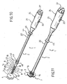
- FIG. 10 depicts an applier 1 having an elongate implement portion 2 dimensionally sized for insertion through a cannula of a trocar or laparoscopic port to tissue walls 3, 4 to anastomose two lumens.
- a distal introducer tip 5 of the applier 1 pierces through an opening 6 at an anastomosis site 7 to position an actuating portion 8 that holds a ring device 9 for single lumen anastomosis and a locking device 42 for latching the ring device 9 in an actuated configuration.
- the ring device 9 has three primary rings, depicted as a proximal ring 10, a center ring 11, and a distal ring 12, that are cylindrically aligned with one another.
- the proximal ring 10 is longitudinally attached to the center ring 11 by proximal arms 13, which in turn is longitudinally attached to the distal ring 12 by distal arms 14.
- Each proximal and distal arm 13, 14 is bisected respectively by a hinged joint 15, 16 defining an inner arm segment 17, 18 also hingedly attaching to the center ring 11 and an outer arm segment 19, 20 also hingedly attached to the respective proximal or distal ring 10, 12. In its unactuated state as depicted in FIG.
- the arms 13, 14 are substantially oblong and the ring device 9 is at least approximately cylindrical.
- the relative lengths of the inner arm segments 17, 18 to outer arm segments 19, 20 may be selected to provide a desired angular contact to tissue walls 3, 4. In the illustrative version, the relationship resembles a cantilevered contact with the inner arm segments 17, 18 actuating to an approximately parallel relationship to the tissue walls 3, 4.
- a handle portion 21 is proximally connected to a shaft 22 of the implement portion 2.
- the shaft 22 may be rigid or flexible, with the latter being desirable for intralumenal insertion, such as through the esophagus.
- the handle 21 includes controls for longitudinally positioning the rings 10, 11, 12 of the ring device 9 and for applying the locking device 42 to the ring device 9.
- the controls include a distal ring slide control 23, a proximal ring slide control 24 as well as a latching slide control 45.
- the handle 21 may further include controls for a distal tip illumination capability so that actuation of the distal arms 14 in the distal lumen may be proximally viewed from an endoscope. It will be appreciated that the terms "proximal” and “distal” are used herein with reference to a clinician gripping the handle portion 21 of the applier 1.
- the distal ring slide control 23 has been withdrawn proximally and the proximal ring slide control 24 has been advanced distally so that both the distal ring 12 and proximal rings 10 are brought into locking proximity of the center ring 11, which remains substantially stationary.
- the proximal and distal arms 13, 14 hinge outwardly from the longitudinal axis of the ring device 9, creating a hollow rivet or hourglass shape for apposing tissue walls 3, 4.
- the center ring 11 sits at a tissue junction between lumens and the distal and proximal rings 12, 10 come to rest in respective lumens.
- the locking device 42 By distally advancing the latching control 45, the locking device 42 has been advanced distally in snap engagement with rings 10, 12 so that the ring device 9 is held in the actuated position with bent arms 13, 14 apposing tissue.
- the proximal arms 13 may be staggered, as depicted, from distal arms 14 to create a tortuous path for the compressed tissue.
- the arms 13, 14 may be aligned to directly mate to each other.
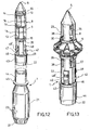
- the locking device 42 comprises an annular proximal shoulder 46 suitable to engage a proximal end surface of the proximal ring 10 and a longitudinal portion 47 which protrudes distally from the proximal shoulder 46 and forms elastically supported snapper teeth 48 extending radially outwardly from the longitudinal portion 47 to enable snap engagement of the distal ring 12.
- the locking device 42 is adapted to latch the ring device 9 at different adjustable distances between the proximal ring 10 and the distal ring 12.
- This feature together with a ring release mechanism of the applier (which will be described in detail below) suitable to release the ring device independently from its particular actuated configuration, make it possible to deploy the anastomotic ring device at different tissue thicknesses and pressure rates and to adjust the ring configuration and tissue pressure during the application of the ring device.
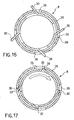
- the longitudinal portion 47 comprises a substantially cylindrical wall defining longitudinal window openings or slots 53 and the snapper teeth 48, 48' are formed on radially elastically deflectable tongues 52 arranged inside said window openings or slots 53 in longitudinally extending rows such that each one of the (at least two) different snapper teeth 48, 48' of a same row (i.e. of the same tongue 52) has a different distance to said proximal shoulder 46 corresponding to different adjustable distances between the proximal and distal rings 10, 12 of the ring device 9.
- the cylindrical wall defines further longitudinal slots 49 in alignment with the proximal catches or arresting surfaces and, preferably, also in alignment with the distal catches of the applier 1 which enable the locking device 42 to be pushed in engagement with the ring device 9 without interfering with these protruding catches of the applier (which will be described in detail below).
- the longitudinal portion 47 of the locking device 42 defines only one circumferential row of snapper teeth 48 (at least two diametrically oppositely arranged snapper teeth formed on two opposite tongues 52, respectively) suitable to snap engage the distal ring 12, but the annular proximal shoulder 46 comprises a distally projecting externally threaded adjusting portion 50 which mates an internal thread provided at the proximal base 51 of the longitudinal portion 47 such that the distance between the shoulder 46 and the snapper teeth 48 is adjustable by screwing the adjusting portion 50 more or less into the longitudinal portion 47.
- the threaded adjusting portion 50 might be slotted in order not to interfere with the catches or arresting surfaces of the applier 1.
- the screw adjustment must be performed in angular steps which correspond to the angular offset of the slots 49 or catches, respectively.
- the shape of the longitudinal portion 47 and the annular proximal shoulder 46 can be identical to those of the first embodiment.
- the locking device 42 comprises coarse adjustment means and additional fine adjustment means.
- the coarse adjustment means are embodied by two or more snapper teeth 48, 48' arranged in each of a plurality of (preferably four) longitudinally extending rows such that the distances between the annular proximal shoulder 46 and the different snapper teeth 48, 48' of a same row correspond to different discretely adjustable distances between the proximal and distal rings 10, 12 of the ring device 9.
- the fine adjustment means are embodied by an externally threaded adjusting portion 50 which protrudes distally from the annular proximal shoulder 46 and mates an internal thread provided at the proximal base 51 of the longitudinal portion 47. In this way, the distance between the shoulder 46 and the discretely selected snapper tooth 48 is continuously fine adjustable by screwing the adjusting portion 50 more or less into the longitudinal portion 47.
- the longitudinal portion 47 comprises preferably a substantially cylindrical wall defining longitudinal window openings or slots 53 and the snapper teeth 48 are formed on (preferably four equidistant) radially elastically deflectable tongues 52 arranged inside said window openings or slots 53.
- the cylindrical wall can be interrupted by further longitudinal slots 49 which enable the locking device 42 to be pushed in engagement with the ring device 9 without interfering with protruding actuating members of the anastomotic applier 1.
- the locking device 42 itself defines a seat for receiving a group of needles or staples such that, during application, the locking device 42 moves in snap engagement with the rings 10, 12 and pushes contemporaneously the group of needles or staples in the anastomotic ring device 9 thereby piercing the tissue 3, 4 held between the proximal and distal ring arms.
- the group of needles might advantageously comprise a self supporting needle ring which can be arranged on the annular shoulder 46 of the locking device 42.
- Figures 12 to 18 illustrate an embodiment of the applier 1 adapted to deploy and actuate the ring device 9 and to apply the locking device 42 to the actuated ring device 9 according to an embodiment of the invention.
- the implement portion 2 comprises a substantially cylindrical housing 25 which defines, in the zone of the actuating portion 8, a plurality of axially extending distal window slots 26 and a plurality of axially extending proximal window slots 27 which extend along the track of the actuation movement of the distal and proximal rings 12, 10, respectively.
- a distal actuating member 28 comprises a shaft 29 slidably received inside the housing 25 and operatively connected with the distal ring slide control 23 via a pull rod 31.
- a plurality of fin shaped distal catches 30 protrude outward from the shaft 29 and extend through the distal window slots 26 such that they engage a distal end surface of the distal ring 12, when in the lock position. In this condition, it is possible to move the distal ring 12 proximally by shifting the distal ring slide control 23 in proximal direction.
- a proximal actuating member 32 comprises a shaft 33 slidably received inside the housing 25 and operatively connected with the proximal ring slide control 24 via a push rod 34.
- a plurality of fin shaped proximal catches 35 protrude outward from the shaft 33 and extend through the proximal window slots 27 such that they engage a proximal end surface of the proximal ring 10, when in the lock position. In this condition, it is possible to move the proximal ring 10 distally by shifting the proximal ring slide control 24 in distal direction.
- the proximal and distal actuating members 28, 32 are configured to translate relative to each other (and preferably independently from one another), but they are advantageously locked to each other in rotation about the longitudinal axis X of the implement portion 2, e.g. by a geometric coupling 36.
- the handle 21 comprises a release control, e.g. a rotating knob 37, coupled to the pull rod 31 and/or to the push rod 34 and adapted to rotate at least the distal actuating member 28 (and preferably both actuating members 28, 32) about the longitudinal axis X of the implement portion 2 from the lock position to a release position in which the catches 30, 35 are disengaged from the anastomotic ring device 9 such that the implement portion of the applier can be proximally withdrawn through the center opening of the ring device 9.
- a release control e.g. a rotating knob 37
- the disengaging of the applier 1 from the ring device 9 is obtained by the feature that, during the rotation of the actuating member 28, 32, a part of the latter slides along a deviating surface at the implement portion, particularly at the housing 25, which is configured to urge the catches 30, 35 radially inward to disengage them at least from the distal ring 12.
- the proximal catches need not necessarily be retracted.
- the catches 30, 35 are preferably inclined or slanted in a direction opposite the direction of rotation from the lock position to the release position, thereby facilitating the inward deviation of the catches by lateral longitudinal edges 38 of the corresponding window slots 26, 27 which embody the above mentioned deviating surfaces.
- the housing 25 and each actuating member 28, 32 is formed from a rigid polymer or sheet metal.
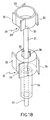
- the applier 1 comprises a latching mechanism adapted to carry the detachable locking device 42 and to apply it to the ring device 9 in its actuated rivet shape.
- the latching mechanism comprises one or more longitudinally translatable push portions 43 arranged proximally with respect to the proximal catches 35 or to stationary proximal arresting surfaces and adapted to engage a proximal end surface of the locking device 42 and to push the locking device 42 distally in engagement with the anastomotic ring device 9.
- the push portions 43 are connected, via a push rod (for instance a tubular push rod 44 externally applied to the implement portion 2) to the latching slide control, for instance a flange portion 45 of the push rod 44 arranged near the handle portion 21. This allows to latch the ring device 9 after its actuation, thereby obviating to automatic latching which might disturb fine adjustment of the ring approximation and of the compression rate applied to the tissue walls 3, 4 clamped by the ring device 9.
- the push portion 43 is rotatably supported at the implement portion 2 and comprises preferably geometrical coupling means (e.g. teeth, recesses) suitable to engaging the annular shoulder 46 of the locking device 42 so that a rotational adjusting movement of the push portion 43 causes the annular shoulder 46 to screw into or unscrew from the longitudinal portion 47 which is preferably prevented to rotate, e.g. by the catches 35, 30 or by stationary arresting surfaces.
- the oblong un-actuated ring device 9 is applied to the actuating portion 8 of the applier 1 and the distale 30 and proximal catches 35 protrude outward through the corresponding window slots 26, 27 and engage the distal and proximal rings 12, 10 of the ring device 9.
- the latching control 45 and the push portion 43 together with the locking device 42 are in a proximally retracted position.
- FIG. 13 illustrates the situation after the distal ring slide control 23 has been shifted proximally and the proximal ring slide control 24 has been shifted distally, causing the actuating members 28, 32 to approximate the distal ring 12 and the proximal ring 10 toward the center ring 11 and the ring device 9 to deform in its actuated rivet shape.
- the latching control 45 and the push portion 43 together with the locking device 42 are still proximally retracted and the distal and proximal catches 30, 35 of the applier 1 are still in their lock position, i.e. they protrude outward and inhibit withdrawal of the applier 1 from the actuated ring device 9.
- FIG. 14 illustrates the situation after the latching control 45 has been slid distally causing the locking device 42 to be pushed in snap engagement with the actuated ring device 9 which is effectively latched.
- the release control 37 has been rotated, thereby rotating the actuating members 28, 32 about the longitudinal axis X from the lock position into the release position, in which the catches 30, 35 are bent inwardly by the window edges 38 and disengage from the ring device 9. It is now possible to remove the applier 1 proximally through the center opening of the actuated and deployed ring device 9, as shown in FIG. 15 .
- the ring device 9 is received upon the actuating portion 8 of the implement portion 2 of the applier 1. Specifically, the proximal ring 10 of the ring device 9 rests against the proximal catches 35 and the distal catches 30 of the distal ring actuating member 28 engage the distal ring 12 of the ring device 9.
- a clinician manipulates the handle 21 to insert the implement portion 2 through the cannula of a trocar, laparoscopic port, or through a lumen such as the esophagus to the anastomosis site 7.
- the tissue walls 3, 4 are distally placed (from the surgeon point of view) and the introducer tip 5 of the implement portion 2 passes through the opening 6 formed in these walls 3, 4.
- the introducer tip may include a piercing shape and/or electromagnetically or thermally enhanced cutting features to assist in forming the opening 6.
- the locking device 42 By sliding the latching slide control 45 distally, the locking device 42 enters within the inner diameter of the ring device 9 and snap engages the distal and proximal rings thereof. It is now possible to disengage the catches 30, 35 that hold the applier 1 to the ring device 9 by rotating the release control 37 which causes the catches to retract radially. Then, the distal tip 5 of the applier is withdrawn from the ring device 9 leaving it deployed to form the anastomotic attachment. Over time, the tissue walls 3, 4 permanently heal together and the ring device 9 as well as the locking device 42 may be passed out of the digestive tract, especially if biofragmentable.
- aspects of the invention have application to surgical procedures performed endoscopically and laparoscopically, as well as an open procedure. Use herein of one of these or similar terms should not be construed to limit the present invention for use in only one category of surgical procedure.
- the locking device is also suitable to be used in connection with double piece anastomotic ring devices of the type comprising two distinct compression rings which are intended to be arranged on either side of the two tissue walls which need to be joined in anastomosis.
- the compression rings are approximated and locked to one another in order to clamp the two tissue walls between them and the anastomotic orifice through the tissue walls is created by widening or resecting the tissue overlapping into an internal passage opening of the compression rings.
Landscapes
- Health & Medical Sciences (AREA)
- Surgery (AREA)
- Life Sciences & Earth Sciences (AREA)
- Biomedical Technology (AREA)
- Nuclear Medicine, Radiotherapy & Molecular Imaging (AREA)
- Engineering & Computer Science (AREA)
- Physiology (AREA)
- Heart & Thoracic Surgery (AREA)
- Medical Informatics (AREA)
- Molecular Biology (AREA)
- Animal Behavior & Ethology (AREA)
- General Health & Medical Sciences (AREA)
- Public Health (AREA)
- Veterinary Medicine (AREA)
- Surgical Instruments (AREA)
Claims (14)
- Dispositif de verrouillage (42) pour un dispositif formant bague d'anastomose (9) du type comprenant au moins une bague proximale (10) et une bague distale (12) destinées à être positionnées de chaque côté de parties de tissu proximale et distale et appropriées pour serrer les parties de tissu proximale et distale entre elles lorsque le dispositif formant bague (9) est actionné, dans lequel les bagues (10, 12) définissent une ouverture de passage centrale à travers le dispositif formant bague (9),
ledit dispositif de verrouillage (42) étant adapté pour verrouiller le dispositif formant bague lorsqu'il est actionné, dans lequel
le dispositif de verrouillage (42) est séparé du dispositif formant bague (9) et peut être inséré dans l'ouverture de passage de celui-ci et comprend :- une première surface de verrouillage (48, 48') adaptée pour venir en prise avec la bague distale (12) et une deuxième surface de verrouillage (46) adaptée pour venir en prise avec la bague proximale (10) pour verrouiller le dispositif formant bague (9) ;caractérisé en ce que le dispositif de verrouillage comprend :- des moyens d'ajustement (50, 51 ; 48, 48') pour placer lesdites première et deuxième surfaces de verrouillage (46 ; 48, 48') à différentes distances les unes par rapport aux autres de manière à verrouiller le dispositif formant bague (9) dans différentes configurations d'actionnement,et en ce que lesdits moyens d'ajustement comprennent des moyens filetés (50, 51) interposés entre lesdites première (48) et deuxième (46) surfaces de verrouillage de sorte que la distance entre les première et deuxième surfaces puisse être ajustée par rotation. - Dispositif de verrouillage (42) selon la revendication 1, comprenant :- un épaulement proximal (46) annulaire approprié pour venir en prise avec une surface d'extrémité proximale de la bague proximale (10) ; et- une partie longitudinale (47) qui fait saillie distalement de l'épaulement proximal (46) et qui forme des dents d'encliquetage (48) supportées de manière élastique s'étendant radialement vers l'extérieur de la partie longitudinale (47) pour permettre une mise en prise par encliquetage de la bague distale (12) ;- une partie d'ajustement (50) filetée qui relie par vissage la partie longitudinale (47) à l'épaulement proximal (46) annulaire de sorte que la distance longitudinale entre l'épaulement proximal (46) annulaire et les dents d'encliquetage (48) puisse être ajustée en vissant la partie d'ajustement (50) par rapport à la partie longitudinale (47).
- Dispositif de verrouillage (42) selon la revendication 2, dans lequel ledit épaulement proximal (46) annulaire comprend une partie d'ajustement (50) filetée extérieurement faisant saillie distalement qui s'accouple à un filetage interne prévu au niveau d'une base proximale (51) de la partie longitudinale (47) de sorte que la distance entre l'épaulement proximal (46) annulaire et les dents d'encliquetage (48) puisse être ajustée en vissant l'épaulement proximal (46) annulaire plus ou moins dans la partie longitudinale (47).
- Dispositif de verrouillage (42) selon la revendication 3, dans lequel la partie longitudinale (47) comprend une paroi sensiblement cylindrique définissant des ouvertures de fenêtre ou fentes (53) longitudinales et les dents d'encliquetage (48) sont formées sur des languettes (52) pouvant être défléchies radialement de manière élastique agencées à l'intérieur desdites ouvertures de fenêtre ou fentes (53).
- Dispositif de verrouillage (42) selon la revendication 4, dans lequel la paroi cylindrique définit en outre des fentes (49) longitudinales qui permettent que le dispositif de verrouillage (42) soit poussé en prise avec le dispositif formant bague (9) sans interférer avec des éléments d'actionnement (30, 35) saillants d'un applicateur d'anastomose (1).
- Dispositif de verrouillage (42) selon la revendication 5, dans lequel la partie d'ajustement (50) filetée est également fendue afin de ne pas interférer avec les éléments d'actionnement (35) de l'applicateur d'anastomose (1).
- Dispositif de verrouillage (42) selon la revendication 1, dans lequel lesdits moyens d'ajustement comprennent deux premières surfaces de verrouillage (48, 48') différentes ou plus agencées en une ou plusieurs rangées s'étendant dans la direction longitudinale du dispositif de verrouillage (42) de sorte que chacune des différentes premières surfaces de verrouillage (48, 48') d'une même rangée soit à une distance différente de ladite deuxième surface de verrouillage (46).
- Dispositif de verrouillage (42) selon la revendication 7, comprenant :- un épaulement proximal (46) annulaire approprié pour venir en prise avec une surface d'extrémité proximale de la bague proximale (10) ; et- une partie longitudinale (47) qui fait saillie distalement de l'épaulement proximal (46) et qui forme des dents d'encliquetage (48, 48') supportées de manière élastique s'étendant radialement vers l'extérieur de la partie longitudinale (47) pour permettre une mise en prise par encliquetage de la bague distale (12),dans lequel lesdites dents d'encliquetage (48, 48') sont agencées en une pluralité de rangées s'étendant longitudinalement de sorte que chacune des différentes dents d'encliquetage (48, 48') d'une même rangée soit à une distance différente dudit épaulement proximal (46).
- Dispositif de verrouillage (42) selon la revendication 8, dans lequel la partie longitudinale (47) comprend une paroi sensiblement cylindrique définissant des ouvertures de fenêtre ou fentes (53) longitudinales et les dents d'encliquetage (48, 48') sont formées sur des languettes (52) pouvant être défléchies radialement de manière élastique agencées à l'intérieur desdites ouvertures de fenêtre ou fentes (53).
- Dispositif de verrouillage (42) selon la revendication 9, dans lequel la paroi cylindrique définit en outre des fentes (49) longitudinales qui permettent que le dispositif de verrouillage (42) soit poussé en prise avec le dispositif formant bague (9) sans interférer avec les éléments d'actionnement (30, 35) saillants d'un applicateur d'anastomose (1).
- Dispositif de verrouillage (42) selon la revendication 1, dans lequel lesdits moyens d'ajustement comprennent des moyens d'ajustement grossier (48, 48') et des moyens d'ajustement fin (50, 51) pour ajuster la distance entre les première et deuxième surfaces de verrouillage (46 ; 48, 48'), dans lequel lesdits moyens d'ajustement fin comprennent les moyens filetés (50, 51).
- Dispositif de verrouillage (42) selon la revendication 11, dans lequel lesdits moyens d'ajustement grossier (48, 48') comprennent deux premières surfaces de verrouillage (48, 48') différentes ou plus agencées en une ou plusieurs rangées s'étendant dans la direction longitudinale du dispositif de verrouillage (42) de sorte que chacune des différentes premières surfaces de verrouillage (48, 48') d'une même rangée soit à une distance différente de ladite deuxième surface de verrouillage (46), qui peut être sélectionnée de manière discrète, et lesdits moyens d'ajustement fin (50, 51) comprennent lesdits moyens filetés (50) interposés entre lesdites première et deuxième surfaces de verrouillage de sorte que la distance entre la première surface de verrouillage (48, 48') sélectionnée de manière discrète et ladite deuxième surface de verrouillage (46) puisse être ajustée en continu en tournant les moyens filetés (50).
- Dispositif de verrouillage (42) selon la revendication 12, comprenant :- un épaulement proximal (46) annulaire approprié pour venir en prise avec une surface d'extrémité proximale de la bague proximale (10) ; et- une partie longitudinale (47) qui fait saillie distalement de l'épaulement proximal (46) et qui forme des dents d'encliquetage (48, 48') supportées de manière élastique s'étendant radialement vers l'extérieur de la partie longitudinale (47) pour permettre une mise en prise par encliquetage de la bague distale (12),dans lequel lesdites dents d'encliquetage (48, 48') sont agencées en une pluralité de rangées s'étendant longitudinalement de sorte que chacune des différentes dents d'encliquetage d'une même rangée soit à une distance différente dudit épaulement proximal (46),- une partie d'ajustement (50) filetée qui relie par vissage la partie longitudinale (47) à l'épaulement proximal (46) annulaire de sorte que la distance longitudinale entre l'épaulement proximal (46) annulaire et les dents d'encliquetage (48, 48') puisse être ajustée en vissant la partie d'ajustement (50) par rapport à la partie longitudinale (47).
- Dispositif d'anastomose comprenant :- un dispositif formant bague (9) comportant des bagues proximale (10), centrale (11) et distale (12) respectivement reliées par des bras (13, 14) articulés proximaux et distaux, les bras (13, 14) articulés ayant une forme radialement rétractée généralement oblongue lorsque le dispositif formant bague (9) n'est pas actionné et une forme faisant saillie radialement pliée lorsque le dispositif formant bague (9) est actionné, lesdites bagues proximale, centrale et distale définissant une ouverture de passage centrale à travers le dispositif formant bague (9) ;- un dispositif de verrouillage (42) selon l'une quelconque des revendications précédentes.
Priority Applications (5)
| Application Number | Priority Date | Filing Date | Title |
|---|---|---|---|
| AT06021056T ATE441366T1 (de) | 2006-10-06 | 2006-10-06 | Verriegelungsvorrichtung für eine anastomosevorrichtung |
| DE602006008956T DE602006008956D1 (de) | 2006-10-06 | 2006-10-06 | Verriegelungsvorrichtung für eine Anastomosevorrichtung |
| EP06021056A EP1908419B1 (fr) | 2006-10-06 | 2006-10-06 | Dispositif de verrouillage pour un dispositif pour l'anastomose |
| PCT/EP2007/056583 WO2008040577A1 (fr) | 2006-10-06 | 2007-06-29 | Dispositif de verrouillage pour un dispositif anastomotique |
| CN2007800372233A CN101522111B (zh) | 2006-10-06 | 2007-06-29 | 用于吻合装置的锁定装置 |
Applications Claiming Priority (1)
| Application Number | Priority Date | Filing Date | Title |
|---|---|---|---|
| EP06021056A EP1908419B1 (fr) | 2006-10-06 | 2006-10-06 | Dispositif de verrouillage pour un dispositif pour l'anastomose |
Publications (2)
| Publication Number | Publication Date |
|---|---|
| EP1908419A1 EP1908419A1 (fr) | 2008-04-09 |
| EP1908419B1 true EP1908419B1 (fr) | 2009-09-02 |
Family
ID=37720824
Family Applications (1)
| Application Number | Title | Priority Date | Filing Date |
|---|---|---|---|
| EP06021056A Active EP1908419B1 (fr) | 2006-10-06 | 2006-10-06 | Dispositif de verrouillage pour un dispositif pour l'anastomose |
Country Status (5)
| Country | Link |
|---|---|
| EP (1) | EP1908419B1 (fr) |
| CN (1) | CN101522111B (fr) |
| AT (1) | ATE441366T1 (fr) |
| DE (1) | DE602006008956D1 (fr) |
| WO (1) | WO2008040577A1 (fr) |
Families Citing this family (10)
| Publication number | Priority date | Publication date | Assignee | Title |
|---|---|---|---|---|
| US7625392B2 (en) | 2006-02-03 | 2009-12-01 | James Coleman | Wound closure devices and methods |
| US8443808B2 (en) | 2007-03-19 | 2013-05-21 | Hologic, Inc. | Methods and apparatus for occlusion of body lumens |
| US9301761B2 (en) * | 2007-10-22 | 2016-04-05 | James E. Coleman | Anastomosis devices and methods |
| US8197498B2 (en) | 2008-11-06 | 2012-06-12 | Trinitas Ventures Ltd. | Gastric bypass devices and procedures |
| US10398445B2 (en) | 2011-01-11 | 2019-09-03 | Amsel Medical Corporation | Method and apparatus for clamping tissue layers and occluding tubular body structures |
| US10820895B2 (en) | 2011-01-11 | 2020-11-03 | Amsel Medical Corporation | Methods and apparatus for fastening and clamping tissue |
| WO2015134768A1 (fr) | 2011-01-11 | 2015-09-11 | Amsel Medical Corporation | Procédé et appareil pour occlure un vaisseau sanguin et/ou d'autres structures tubulaires |
| US9247930B2 (en) | 2011-12-21 | 2016-02-02 | James E. Coleman | Devices and methods for occluding or promoting fluid flow |
| WO2014182849A1 (fr) | 2013-05-07 | 2014-11-13 | Amsel Medical Corporation | Procédé et appareil pour réaliser l'occlusion d'un vaisseau sanguin et/ou pour fixer au moins deux objets ensemble |
| CN108056796A (zh) * | 2017-12-28 | 2018-05-22 | 兰州西脉记忆合金股份有限公司 | 一次性自加压式肠道吻合器 |
Family Cites Families (8)
| Publication number | Priority date | Publication date | Assignee | Title |
|---|---|---|---|---|
| CA1243246A (fr) * | 1983-03-17 | 1988-10-18 | Robert W. Mericle | Dispositif d'anastomose |
| GR1002290B (el) * | 1991-06-03 | 1996-05-02 | Ethicon Inc. | Απορροφησιμο αναστομωτικο μεσο συνδεσεως. |
| US5904697A (en) * | 1995-02-24 | 1999-05-18 | Heartport, Inc. | Devices and methods for performing a vascular anastomosis |
| SE509389C2 (sv) * | 1996-07-24 | 1999-01-18 | Solem Jan Otto | Anordning för anslutning av änden av ett första blodkärl till sidan av ett andra blodkärl |
| US7029482B1 (en) * | 2002-01-22 | 2006-04-18 | Cardica, Inc. | Integrated anastomosis system |
| US7452363B2 (en) * | 2003-09-30 | 2008-11-18 | Ethicon Endo-Surgery, Inc. | Applier for fastener for single lumen access anastomosis |
| US8257389B2 (en) * | 2004-05-07 | 2012-09-04 | W.L. Gore & Associates, Inc. | Catching mechanisms for tubular septal occluder |
| WO2006102213A1 (fr) * | 2005-03-18 | 2006-09-28 | Nmt Medical, Inc. | Element de retention pour occluseur de pfo |
-
2006
- 2006-10-06 DE DE602006008956T patent/DE602006008956D1/de active Active
- 2006-10-06 EP EP06021056A patent/EP1908419B1/fr active Active
- 2006-10-06 AT AT06021056T patent/ATE441366T1/de not_active IP Right Cessation
-
2007
- 2007-06-29 CN CN2007800372233A patent/CN101522111B/zh not_active Expired - Fee Related
- 2007-06-29 WO PCT/EP2007/056583 patent/WO2008040577A1/fr not_active Ceased
Also Published As
| Publication number | Publication date |
|---|---|
| CN101522111B (zh) | 2011-03-02 |
| ATE441366T1 (de) | 2009-09-15 |
| CN101522111A (zh) | 2009-09-02 |
| EP1908419A1 (fr) | 2008-04-09 |
| DE602006008956D1 (de) | 2009-10-15 |
| WO2008040577A1 (fr) | 2008-04-10 |
Similar Documents
| Publication | Publication Date | Title |
|---|---|---|
| US7871418B2 (en) | Applier for fastener for single lumen access anastomosis | |
| EP1520530B1 (fr) | Applicateur et une bague d'anastomose | |
| EP1520527B1 (fr) | Dispositif d'anastomose | |
| CN101522111B (zh) | 用于吻合装置的锁定装置 | |
| US8211142B2 (en) | Method for hybrid gastro-jejunostomy | |
| EP1908418A1 (fr) | Applicateur d'anastomose | |
| US20050101977A1 (en) | Method and device for use in endoscopic organ procedures | |
| WO2008040582A1 (fr) | dispositif à anneaux anastomotiques avec moyen de verrouillage | |
| US20050070939A1 (en) | Unfolding anastomosis ring device | |
| US20090292163A1 (en) | Devices and methods for achieving the laparoscopic delivery of a device | |
| AU2007201158A1 (en) | Method for hybrid gastro-jejunostomy |
Legal Events
| Date | Code | Title | Description |
|---|---|---|---|
| PUAI | Public reference made under article 153(3) epc to a published international application that has entered the european phase |
Free format text: ORIGINAL CODE: 0009012 |
|
| AK | Designated contracting states |
Kind code of ref document: A1 Designated state(s): AT BE BG CH CY CZ DE DK EE ES FI FR GB GR HU IE IS IT LI LT LU LV MC NL PL PT RO SE SI SK TR |
|
| AX | Request for extension of the european patent |
Extension state: AL BA HR MK RS |
|
| 17P | Request for examination filed |
Effective date: 20080923 |
|
| 17Q | First examination report despatched |
Effective date: 20081103 |
|
| AKX | Designation fees paid |
Designated state(s): AT BE BG CH CY CZ DE DK EE ES FI FR GB GR HU IE IS IT LI LT LU LV MC NL PL PT RO SE SI SK TR |
|
| AXX | Extension fees paid |
Extension state: RS Payment date: 20080923 Extension state: HR Payment date: 20080923 Extension state: AL Payment date: 20080923 Extension state: BA Payment date: 20080923 Extension state: MK Payment date: 20080923 |
|
| GRAP | Despatch of communication of intention to grant a patent |
Free format text: ORIGINAL CODE: EPIDOSNIGR1 |
|
| GRAS | Grant fee paid |
Free format text: ORIGINAL CODE: EPIDOSNIGR3 |
|
| GRAA | (expected) grant |
Free format text: ORIGINAL CODE: 0009210 |
|
| AK | Designated contracting states |
Kind code of ref document: B1 Designated state(s): AT BE BG CH CY CZ DE DK EE ES FI FR GB GR HU IE IS IT LI LT LU LV MC NL PL PT RO SE SI SK TR |
|
| AX | Request for extension of the european patent |
Extension state: AL BA HR MK RS |
|
| REG | Reference to a national code |
Ref country code: CH Ref legal event code: EP |
|
| REG | Reference to a national code |
Ref country code: IE Ref legal event code: FG4D |
|
| REF | Corresponds to: |
Ref document number: 602006008956 Country of ref document: DE Date of ref document: 20091015 Kind code of ref document: P |
|
| PG25 | Lapsed in a contracting state [announced via postgrant information from national office to epo] |
Ref country code: LT Free format text: LAPSE BECAUSE OF FAILURE TO SUBMIT A TRANSLATION OF THE DESCRIPTION OR TO PAY THE FEE WITHIN THE PRESCRIBED TIME-LIMIT Effective date: 20090902 Ref country code: FI Free format text: LAPSE BECAUSE OF FAILURE TO SUBMIT A TRANSLATION OF THE DESCRIPTION OR TO PAY THE FEE WITHIN THE PRESCRIBED TIME-LIMIT Effective date: 20090902 Ref country code: SE Free format text: LAPSE BECAUSE OF FAILURE TO SUBMIT A TRANSLATION OF THE DESCRIPTION OR TO PAY THE FEE WITHIN THE PRESCRIBED TIME-LIMIT Effective date: 20090902 |
|
| PGFP | Annual fee paid to national office [announced via postgrant information from national office to epo] |
Ref country code: AT Payment date: 20091028 Year of fee payment: 4 Ref country code: DK Payment date: 20091029 Year of fee payment: 4 Ref country code: ES Payment date: 20091029 Year of fee payment: 4 Ref country code: IE Payment date: 20091029 Year of fee payment: 4 Ref country code: LU Payment date: 20091102 Year of fee payment: 4 Ref country code: MC Payment date: 20091028 Year of fee payment: 4 |
|
| NLV1 | Nl: lapsed or annulled due to failure to fulfill the requirements of art. 29p and 29m of the patents act | ||
| LTIE | Lt: invalidation of european patent or patent extension |
Effective date: 20090902 |
|
| PG25 | Lapsed in a contracting state [announced via postgrant information from national office to epo] |
Ref country code: SI Free format text: LAPSE BECAUSE OF FAILURE TO SUBMIT A TRANSLATION OF THE DESCRIPTION OR TO PAY THE FEE WITHIN THE PRESCRIBED TIME-LIMIT Effective date: 20090902 Ref country code: NL Free format text: LAPSE BECAUSE OF FAILURE TO SUBMIT A TRANSLATION OF THE DESCRIPTION OR TO PAY THE FEE WITHIN THE PRESCRIBED TIME-LIMIT Effective date: 20090902 Ref country code: PL Free format text: LAPSE BECAUSE OF FAILURE TO SUBMIT A TRANSLATION OF THE DESCRIPTION OR TO PAY THE FEE WITHIN THE PRESCRIBED TIME-LIMIT Effective date: 20090902 Ref country code: LV Free format text: LAPSE BECAUSE OF FAILURE TO SUBMIT A TRANSLATION OF THE DESCRIPTION OR TO PAY THE FEE WITHIN THE PRESCRIBED TIME-LIMIT Effective date: 20090902 |
|
| PGFP | Annual fee paid to national office [announced via postgrant information from national office to epo] |
Ref country code: NL Payment date: 20091025 Year of fee payment: 4 |
|
| PG25 | Lapsed in a contracting state [announced via postgrant information from national office to epo] |
Ref country code: CY Free format text: LAPSE BECAUSE OF FAILURE TO SUBMIT A TRANSLATION OF THE DESCRIPTION OR TO PAY THE FEE WITHIN THE PRESCRIBED TIME-LIMIT Effective date: 20090902 |
|
| PG25 | Lapsed in a contracting state [announced via postgrant information from national office to epo] |
Ref country code: CZ Free format text: LAPSE BECAUSE OF FAILURE TO SUBMIT A TRANSLATION OF THE DESCRIPTION OR TO PAY THE FEE WITHIN THE PRESCRIBED TIME-LIMIT Effective date: 20090902 Ref country code: RO Free format text: LAPSE BECAUSE OF FAILURE TO SUBMIT A TRANSLATION OF THE DESCRIPTION OR TO PAY THE FEE WITHIN THE PRESCRIBED TIME-LIMIT Effective date: 20090902 Ref country code: EE Free format text: LAPSE BECAUSE OF FAILURE TO SUBMIT A TRANSLATION OF THE DESCRIPTION OR TO PAY THE FEE WITHIN THE PRESCRIBED TIME-LIMIT Effective date: 20090902 Ref country code: ES Free format text: LAPSE BECAUSE OF FAILURE TO SUBMIT A TRANSLATION OF THE DESCRIPTION OR TO PAY THE FEE WITHIN THE PRESCRIBED TIME-LIMIT Effective date: 20091213 Ref country code: PT Free format text: LAPSE BECAUSE OF FAILURE TO SUBMIT A TRANSLATION OF THE DESCRIPTION OR TO PAY THE FEE WITHIN THE PRESCRIBED TIME-LIMIT Effective date: 20100104 Ref country code: IS Free format text: LAPSE BECAUSE OF FAILURE TO SUBMIT A TRANSLATION OF THE DESCRIPTION OR TO PAY THE FEE WITHIN THE PRESCRIBED TIME-LIMIT Effective date: 20100102 |
|
| PG25 | Lapsed in a contracting state [announced via postgrant information from national office to epo] |
Ref country code: SK Free format text: LAPSE BECAUSE OF FAILURE TO SUBMIT A TRANSLATION OF THE DESCRIPTION OR TO PAY THE FEE WITHIN THE PRESCRIBED TIME-LIMIT Effective date: 20090902 |
|
| PGFP | Annual fee paid to national office [announced via postgrant information from national office to epo] |
Ref country code: BE Payment date: 20091027 Year of fee payment: 4 |
|
| PG25 | Lapsed in a contracting state [announced via postgrant information from national office to epo] |
Ref country code: BE Free format text: LAPSE BECAUSE OF FAILURE TO SUBMIT A TRANSLATION OF THE DESCRIPTION OR TO PAY THE FEE WITHIN THE PRESCRIBED TIME-LIMIT Effective date: 20090902 Ref country code: AT Free format text: LAPSE BECAUSE OF FAILURE TO SUBMIT A TRANSLATION OF THE DESCRIPTION OR TO PAY THE FEE WITHIN THE PRESCRIBED TIME-LIMIT Effective date: 20090902 Ref country code: DK Free format text: LAPSE BECAUSE OF NON-PAYMENT OF DUE FEES Effective date: 20090902 |
|
| PLBE | No opposition filed within time limit |
Free format text: ORIGINAL CODE: 0009261 |
|
| STAA | Information on the status of an ep patent application or granted ep patent |
Free format text: STATUS: NO OPPOSITION FILED WITHIN TIME LIMIT |
|
| 26N | No opposition filed |
Effective date: 20100603 |
|
| PG25 | Lapsed in a contracting state [announced via postgrant information from national office to epo] |
Ref country code: GR Free format text: LAPSE BECAUSE OF FAILURE TO SUBMIT A TRANSLATION OF THE DESCRIPTION OR TO PAY THE FEE WITHIN THE PRESCRIBED TIME-LIMIT Effective date: 20091203 |
|
| PG25 | Lapsed in a contracting state [announced via postgrant information from national office to epo] |
Ref country code: BG Free format text: LAPSE BECAUSE OF FAILURE TO SUBMIT A TRANSLATION OF THE DESCRIPTION OR TO PAY THE FEE WITHIN THE PRESCRIBED TIME-LIMIT Effective date: 20091031 |
|
| PG25 | Lapsed in a contracting state [announced via postgrant information from national office to epo] |
Ref country code: MC Free format text: LAPSE BECAUSE OF NON-PAYMENT OF DUE FEES Effective date: 20101031 |
|
| REG | Reference to a national code |
Ref country code: CH Ref legal event code: PL |
|
| PG25 | Lapsed in a contracting state [announced via postgrant information from national office to epo] |
Ref country code: HU Free format text: LAPSE BECAUSE OF FAILURE TO SUBMIT A TRANSLATION OF THE DESCRIPTION OR TO PAY THE FEE WITHIN THE PRESCRIBED TIME-LIMIT Effective date: 20100303 |
|
| PG25 | Lapsed in a contracting state [announced via postgrant information from national office to epo] |
Ref country code: CH Free format text: LAPSE BECAUSE OF NON-PAYMENT OF DUE FEES Effective date: 20101031 Ref country code: LI Free format text: LAPSE BECAUSE OF NON-PAYMENT OF DUE FEES Effective date: 20101031 |
|
| PG25 | Lapsed in a contracting state [announced via postgrant information from national office to epo] |
Ref country code: TR Free format text: LAPSE BECAUSE OF FAILURE TO SUBMIT A TRANSLATION OF THE DESCRIPTION OR TO PAY THE FEE WITHIN THE PRESCRIBED TIME-LIMIT Effective date: 20090902 |
|
| PG25 | Lapsed in a contracting state [announced via postgrant information from national office to epo] |
Ref country code: IE Free format text: LAPSE BECAUSE OF NON-PAYMENT OF DUE FEES Effective date: 20101006 |
|
| PG25 | Lapsed in a contracting state [announced via postgrant information from national office to epo] |
Ref country code: LU Free format text: LAPSE BECAUSE OF NON-PAYMENT OF DUE FEES Effective date: 20101006 |
|
| REG | Reference to a national code |
Ref country code: FR Ref legal event code: PLFP Year of fee payment: 11 |
|
| REG | Reference to a national code |
Ref country code: FR Ref legal event code: PLFP Year of fee payment: 12 |
|
| REG | Reference to a national code |
Ref country code: FR Ref legal event code: PLFP Year of fee payment: 13 |
|
| PGFP | Annual fee paid to national office [announced via postgrant information from national office to epo] |
Ref country code: DE Payment date: 20180925 Year of fee payment: 13 |
|
| PGFP | Annual fee paid to national office [announced via postgrant information from national office to epo] |
Ref country code: FR Payment date: 20190913 Year of fee payment: 14 |
|
| PGFP | Annual fee paid to national office [announced via postgrant information from national office to epo] |
Ref country code: IT Payment date: 20191009 Year of fee payment: 14 |
|
| PGFP | Annual fee paid to national office [announced via postgrant information from national office to epo] |
Ref country code: GB Payment date: 20191003 Year of fee payment: 14 |
|
| REG | Reference to a national code |
Ref country code: DE Ref legal event code: R119 Ref document number: 602006008956 Country of ref document: DE |
|
| PG25 | Lapsed in a contracting state [announced via postgrant information from national office to epo] |
Ref country code: DE Free format text: LAPSE BECAUSE OF NON-PAYMENT OF DUE FEES Effective date: 20200501 |
|
| GBPC | Gb: european patent ceased through non-payment of renewal fee |
Effective date: 20201006 |
|
| PG25 | Lapsed in a contracting state [announced via postgrant information from national office to epo] |
Ref country code: FR Free format text: LAPSE BECAUSE OF NON-PAYMENT OF DUE FEES Effective date: 20201031 |
|
| PG25 | Lapsed in a contracting state [announced via postgrant information from national office to epo] |
Ref country code: GB Free format text: LAPSE BECAUSE OF NON-PAYMENT OF DUE FEES Effective date: 20201006 |
|
| PG25 | Lapsed in a contracting state [announced via postgrant information from national office to epo] |
Ref country code: IT Free format text: LAPSE BECAUSE OF NON-PAYMENT OF DUE FEES Effective date: 20201006 |