EP1908360A1 - On line formation of recessed cigarette filter - Google Patents
On line formation of recessed cigarette filter Download PDFInfo
- Publication number
- EP1908360A1 EP1908360A1 EP07021885A EP07021885A EP1908360A1 EP 1908360 A1 EP1908360 A1 EP 1908360A1 EP 07021885 A EP07021885 A EP 07021885A EP 07021885 A EP07021885 A EP 07021885A EP 1908360 A1 EP1908360 A1 EP 1908360A1
- Authority
- EP
- European Patent Office
- Prior art keywords
- substrate
- particulate material
- filter
- layer
- particulate
- Prior art date
- Legal status (The legal status is an assumption and is not a legal conclusion. Google has not performed a legal analysis and makes no representation as to the accuracy of the status listed.)
- Granted
Links
- 235000019504 cigarettes Nutrition 0.000 title claims abstract description 19
- 230000015572 biosynthetic process Effects 0.000 title description 8
- 239000000758 substrate Substances 0.000 claims abstract description 55
- 239000011236 particulate material Substances 0.000 claims abstract description 41
- 239000000779 smoke Substances 0.000 claims abstract description 15
- 238000000034 method Methods 0.000 claims description 17
- 239000003463 adsorbent Substances 0.000 claims description 9
- 239000000796 flavoring agent Substances 0.000 claims description 7
- 235000019634 flavors Nutrition 0.000 claims description 7
- 239000003054 catalyst Substances 0.000 claims description 5
- 238000000151 deposition Methods 0.000 claims description 5
- 238000011144 upstream manufacturing Methods 0.000 claims 2
- 239000010410 layer Substances 0.000 description 11
- OKTJSMMVPCPJKN-UHFFFAOYSA-N Carbon Chemical compound [C] OKTJSMMVPCPJKN-UHFFFAOYSA-N 0.000 description 8
- 229920002301 cellulose acetate Polymers 0.000 description 8
- 239000000463 material Substances 0.000 description 8
- 239000011230 binding agent Substances 0.000 description 5
- 229910052799 carbon Inorganic materials 0.000 description 4
- 238000004924 electrostatic deposition Methods 0.000 description 4
- VYPSYNLAJGMNEJ-UHFFFAOYSA-N Silicium dioxide Chemical compound O=[Si]=O VYPSYNLAJGMNEJ-UHFFFAOYSA-N 0.000 description 3
- 239000012943 hotmelt Substances 0.000 description 3
- 238000012546 transfer Methods 0.000 description 3
- 241000208125 Nicotiana Species 0.000 description 2
- 235000002637 Nicotiana tabacum Nutrition 0.000 description 2
- 150000001299 aldehydes Chemical class 0.000 description 2
- 238000010924 continuous production Methods 0.000 description 2
- 238000004519 manufacturing process Methods 0.000 description 2
- 239000002245 particle Substances 0.000 description 2
- IRLPACMLTUPBCL-KQYNXXCUSA-N 5'-adenylyl sulfate Chemical compound C1=NC=2C(N)=NC=NC=2N1[C@@H]1O[C@H](COP(O)(=O)OS(O)(=O)=O)[C@@H](O)[C@H]1O IRLPACMLTUPBCL-KQYNXXCUSA-N 0.000 description 1
- 229920003043 Cellulose fiber Polymers 0.000 description 1
- 229910021536 Zeolite Inorganic materials 0.000 description 1
- 229910001870 ammonium persulfate Inorganic materials 0.000 description 1
- 238000000429 assembly Methods 0.000 description 1
- 230000000712 assembly Effects 0.000 description 1
- 238000010276 construction Methods 0.000 description 1
- 238000013461 design Methods 0.000 description 1
- HNPSIPDUKPIQMN-UHFFFAOYSA-N dioxosilane;oxo(oxoalumanyloxy)alumane Chemical compound O=[Si]=O.O=[Al]O[Al]=O HNPSIPDUKPIQMN-UHFFFAOYSA-N 0.000 description 1
- 238000001035 drying Methods 0.000 description 1
- 238000003780 insertion Methods 0.000 description 1
- 230000037431 insertion Effects 0.000 description 1
- 239000004816 latex Substances 0.000 description 1
- 229920000126 latex Polymers 0.000 description 1
- 239000007788 liquid Substances 0.000 description 1
- 238000012986 modification Methods 0.000 description 1
- 230000004048 modification Effects 0.000 description 1
- 239000004745 nonwoven fabric Substances 0.000 description 1
- 238000005096 rolling process Methods 0.000 description 1
- 239000000741 silica gel Substances 0.000 description 1
- 229910002027 silica gel Inorganic materials 0.000 description 1
- 239000000377 silicon dioxide Substances 0.000 description 1
- 239000002356 single layer Substances 0.000 description 1
- 230000000391 smoking effect Effects 0.000 description 1
- 239000002344 surface layer Substances 0.000 description 1
- 239000010457 zeolite Substances 0.000 description 1
Images

Classifications
-
- A—HUMAN NECESSITIES
- A24—TOBACCO; CIGARS; CIGARETTES; SIMULATED SMOKING DEVICES; SMOKERS' REQUISITES
- A24D—CIGARS; CIGARETTES; TOBACCO SMOKE FILTERS; MOUTHPIECES FOR CIGARS OR CIGARETTES; MANUFACTURE OF TOBACCO SMOKE FILTERS OR MOUTHPIECES
- A24D3/00—Tobacco smoke filters, e.g. filter-tips, filtering inserts; Filters specially adapted for simulated smoking devices; Mouthpieces for cigars or cigarettes
- A24D3/02—Manufacture of tobacco smoke filters
- A24D3/0204—Preliminary operations before the filter rod forming process, e.g. crimping, blooming
- A24D3/0212—Applying additives to filter materials
- A24D3/0225—Applying additives to filter materials with solid additives, e.g. incorporation of a granular product
-
- A—HUMAN NECESSITIES
- A24—TOBACCO; CIGARS; CIGARETTES; SIMULATED SMOKING DEVICES; SMOKERS' REQUISITES
- A24D—CIGARS; CIGARETTES; TOBACCO SMOKE FILTERS; MOUTHPIECES FOR CIGARS OR CIGARETTES; MANUFACTURE OF TOBACCO SMOKE FILTERS OR MOUTHPIECES
- A24D3/00—Tobacco smoke filters, e.g. filter-tips, filtering inserts; Filters specially adapted for simulated smoking devices; Mouthpieces for cigars or cigarettes
- A24D3/02—Manufacture of tobacco smoke filters
- A24D3/0275—Manufacture of tobacco smoke filters for filters with special features
- A24D3/0287—Manufacture of tobacco smoke filters for filters with special features for composite filters
-
- A—HUMAN NECESSITIES
- A24—TOBACCO; CIGARS; CIGARETTES; SIMULATED SMOKING DEVICES; SMOKERS' REQUISITES
- A24D—CIGARS; CIGARETTES; TOBACCO SMOKE FILTERS; MOUTHPIECES FOR CIGARS OR CIGARETTES; MANUFACTURE OF TOBACCO SMOKE FILTERS OR MOUTHPIECES
- A24D3/00—Tobacco smoke filters, e.g. filter-tips, filtering inserts; Filters specially adapted for simulated smoking devices; Mouthpieces for cigars or cigarettes
- A24D3/06—Use of materials for tobacco smoke filters
- A24D3/16—Use of materials for tobacco smoke filters of inorganic materials
- A24D3/163—Carbon
Definitions
- the present invention relates to the formation of recessed cigarette filters, and more particularly to the on line formation of filters that include smoke altering particulate material such as catalysts, adsorbents, flavors and the like.
- Many filter making procedures include combining a number of independent filter components fabricated beforehand, stored and then combined into a particular cigarette filter design, such as a plug-space-plug configuration. Such procedures require a number of steps which can be eliminated with on line formation of the filter components, such as the step of storing the preformed filter components before assembly.
- one of the objects of the present invention is a procedure for the on line formation of cigarette filters in the production of cigarettes.
- Another object of the present invention is a procedure for on line formation of filters which enables variation of the process parameters to produce filters of different construction and efficiency.
- Still another object of the present invention is a filter making process which is simple, but highly effective in producing cigarette filters at high production speeds.
- an electrostatic deposition or other process such as xerography or electrophotography that allows the formation of a layer of smoke altering particulate material on a paper substrate or the filter paper or any other suitable substrate is used on line to create an active layer in the recessed area of a cigarette filter.
- the amount of smoke altering particulate material can be varied depending on the strength of the applied field and coverage on the filter paper.
- the particulate material may be bound together using small amounts of a hot melt binder. Hot melt binders are preferred over solution or latex binders which may require extensive drying for the removal of the liquid carrier. Moreover, the use of such a binder to keep the particulate material bound to the surface of the paper does not render the material inactive.
- a wide variety of particulates may be deposited in this manner such as catalysts, flavors and adsorbents, for example.
- Particulate material may be introduced in the electrostatically deposited layer to assist in the removal of specific components in the tobacco smoke stream.
- Silicas could be used to remove specific aldehydes, for example.
- the electrostatically deposited layer could also include a combination of particulates such as a carbon adsorbent and a flavorant that enhances the flavor or subjective characteristics of the cigarette. This along with the ability to apply the layer on line improves the flexibility of the cigarette designer in terms of smoke delivery and increases the ability to control the quality of the entire process.
- Another aspect of the invention deals with the use of nonwovens in place of particulate laden paper.
- a nonwoven activated carbon piece may be used in place of carbon filled paper.
- cellulose fibers used in the carbon filled paper are hygroreactive and may tend to make the smoke dry. Accordingly, use of a paperless nonwoven with activated carbon adsorbent could improve the subjective characteristics experienced during the smoking process.
- Figure 1 illustrates an arrangement for depositing particulate material 10 from a first supply 12 onto a continuous thin flexible substrate 14.
- the substrate may be paper or nonwoven material, for example, and the particulate material 10 may comprise any smoke altering particles such as adsorbents, catalysts and flavorants.
- Adsorbents may include carbon, zeolite, APS silica gel and other adsorbent materials alone or in combination with one another.
- silica is particularly effective for removing specific aldehydes from tobacco smoke.
- An electrostatic charge is applied onto the substrate 14 by any suitable mechanism such as the corona discharge device 16 shown in Figure 1.
- the strength of the charge is selected in accordance with the thickness of particulate material coated onto the substrate 14 with higher charges producing greater thickness.
- the substrate becomes coated with the material.
- the particles may be bound together using small amounts of hot melt binder, if desired.
- the coated substrate may pass through the nip of a pair of rollers 18 to fuse or otherwise press the particulate material 10 into the substrate 14, as shown in Figure 1.
- the particulate material may be deposited in a single pass or multiple layers may be applied to the substrate.
- a second supply 12A of the same or different particulate 10A deposits another layer on the first deposited layer, and rollers 18A press the material onto the substrate.
- the particulate coated substrate 14 is then cut into pieces by cutter 20 and those pieces are deposited into cavities between spaced apart filter components, as explained more fully below.
- the cut pieces are formed into a cylindrical plug 22 by rolling the coated substrate piece into that configuration.
- Figures 1 and 2 illustrate the plug 22, and in Figure 2 flap 24 is ready for folding over to complete the plug form.
- Figure 3 illustrates an arrangement for producing a continuous line of plug-space-plug filters.
- This arrangement includes filter paper 26 with spaced apart plugs 28 of cellulose acetate on the filter paper. Cavities 30 are located between the cellulose acetate plugs, and the plug rolls 22 of particulate coated substrate are deposited into these cavities.
- the continuous filter of Figure 3 is cut at 32 into the plug-space-plug filter 34 shown as in Figure 4.
- the spaced apart cellulose acetate plugs 28 A and B define the cavity 30 into which the plug roll 22 has been deposited.
- the filter paper 26 surrounds this assembly.
- FIG 5 illustrates an alternative embodiment of the present invention where the filter paper 26 is coated with particulate material 10B from a source 12B.
- an electrostatic charge is applied to the filter paper 26 with charger device 16.
- the filter paper 30 with particulate thereon passes through the rollers 18 and thereafter cellulose acetate plugs 28 are appropriately positioned on the coated filter paper.
- the coated filter paper is ultimately wrapped around the spaced apart cellulose acetate plugs 28 with plows 36 and the continuous filter arrangement is later cut into individual cigarette filter assemblies, such as shown in Figure 4.
- the cavities are somewhat hollow and the smoke altering particulate material 10 is in the form of an inside surface layer within the cavity 30.
- Figure 6 shows the filter paper 26 coated with the particulate material 10B.
- Figure 7 illustrates another embodiment of the present invention where the continuous thin flexible substrate 14 is indirectly coated with particulate material 10C.
- a rotating transfer roll 30 receives an electrostatic charge from device 16, and particulate material 10C is deposited on the charged surface of the roll from a supply 12C.
- the particulate material on the surface of the roll is transferred onto substrate 14 by suction, from a plenum 32, for example. Thereafter, the layer of material 10C passes through the nip of rollers 18 to fuse or otherwise press the material into the substrate.
- the coated substrate is subsequently cut and formed into filter pieces, as described above.
- Figure 7 also illustrates an optional second transfer station 30A for depositing another layer on the substrate similar to the system described above in conjunction with Figure 1.
- the layer of particulate material 10D of Figure 8 is deposited on substrate 14 in pattern form.
- the charging device may be constructed and arranged to place a pattered charge on the substrate, and the particulate only adheres to the substrate at the charged portions thereof.
- Figure 9 shows an arrangement for applying particulate material layers 10 and 10E on opposite sides of substrate 14.
- a first supply 12 of particulate material is located on one side of the substrate and a second supply 12E is located on the other side of the substrate.
- An electrostatic charge is applied to both sides of substrate 14 by devices 16 and 16E. Otherwise the system is similar to Figure 1, and the coated substrate is formed into filter components in the same manner as described above.
- Figure 10 is cross-sectional view of a filter component 40 similar to the one shown in Figure 2. However, in filter component 40 the substrate 14 coated with particulate material is crimped prior to being roll formed into its final configuration.
Landscapes
- Chemical & Material Sciences (AREA)
- Engineering & Computer Science (AREA)
- Materials Engineering (AREA)
- Inorganic Chemistry (AREA)
- Cigarettes, Filters, And Manufacturing Of Filters (AREA)
- Laminated Bodies (AREA)
- Inorganic Compounds Of Heavy Metals (AREA)
- Manufacturing Of Cigar And Cigarette Tobacco (AREA)
- Filtering Materials (AREA)
- Catalysts (AREA)
Abstract
Description
- The present invention relates to the formation of recessed cigarette filters, and more particularly to the on line formation of filters that include smoke altering particulate material such as catalysts, adsorbents, flavors and the like.
- Many filter making procedures include combining a number of independent filter components fabricated beforehand, stored and then combined into a particular cigarette filter design, such as a plug-space-plug configuration. Such procedures require a number of steps which can be eliminated with on line formation of the filter components, such as the step of storing the preformed filter components before assembly.
- Accordingly, one of the objects of the present invention is a procedure for the on line formation of cigarette filters in the production of cigarettes.
- Another object of the present invention is a procedure for on line formation of filters which enables variation of the process parameters to produce filters of different construction and efficiency.
- Still another object of the present invention is a filter making process which is simple, but highly effective in producing cigarette filters at high production speeds.
- In accordance with the present invention, an electrostatic deposition or other process such as xerography or electrophotography that allows the formation of a layer of smoke altering particulate material on a paper substrate or the filter paper or any other suitable substrate is used on line to create an active layer in the recessed area of a cigarette filter. The amount of smoke altering particulate material can be varied depending on the strength of the applied field and coverage on the filter paper. The particulate material may be bound together using small amounts of a hot melt binder. Hot melt binders are preferred over solution or latex binders which may require extensive drying for the removal of the liquid carrier. Moreover, the use of such a binder to keep the particulate material bound to the surface of the paper does not render the material inactive. A wide variety of particulates may be deposited in this manner such as catalysts, flavors and adsorbents, for example.
- Particulate material may be introduced in the electrostatically deposited layer to assist in the removal of specific components in the tobacco smoke stream. Silicas could be used to remove specific aldehydes, for example.
- The electrostatically deposited layer could also include a combination of particulates such as a carbon adsorbent and a flavorant that enhances the flavor or subjective characteristics of the cigarette. This along with the ability to apply the layer on line improves the flexibility of the cigarette designer in terms of smoke delivery and increases the ability to control the quality of the entire process.
- Another aspect of the invention deals with the use of nonwovens in place of particulate laden paper. For example, a nonwoven activated carbon piece may be used in place of carbon filled paper. Under some circumstances cellulose fibers used in the carbon filled paper are hygroreactive and may tend to make the smoke dry. Accordingly, use of a paperless nonwoven with activated carbon adsorbent could improve the subjective characteristics experienced during the smoking process.
- Novel features and advantages of the present invention in addition to those mentioned above will become apparent to persons of ordinary skill in the art from a reading of the following detailed description in conjunction with the accompanying drawings wherein similar reference characters refer to similar parts and in which:
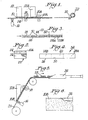
- Figure 1 is a schematic diagrammatic view illustrating on line electrostatic deposition of particulate material onto a substrate and formation of the particulate coated substrate into plug form for on line insertion into the cavities between a continuous line of spaced apart cellulose acetate plugs;
- Figure 2 is a side elevational view of the particulate plug of Figure 1 after being cut and prior to the flap being folded over to complete the plug form;
- Figure 3 is a schematic diagrammatic view illustrating the plugs of Figure 1 inserted into the cavities between spaced apart cellulose acetate plugs in the continuous production of cigarette filters;
- Figure 4 is a complete plug-space-plug cigarette filter with a particulate plug in the cavity between two cellulose acetate plugs;
- Figure 5 is a schematic diagrammatic view illustrating an alternate process for on line electrostatic deposition of particulate material onto filter paper during the continuous production of plug-space-plug cigarette filters;
- Figure 6 is a plan view of the cigarette filter paper of Figure 5 with smoke altering material electrostatically deposited on the paper;
- Figure 7 is a schematic diagrammatic view illustrating still another procedure for on line electrostatic deposition of particulate material onto filter paper by indirect transfer;
- Figure 8 shows particulate material electrostatically deposited on the paper in pattern form;
- Figure 9 is another schematic diagrammatic view showing particulate material deposited on both sides of a suitable substrate; and
- Figure 10 is an end elevated view of a roll formed filter component where the particulate coated substrate is crimped before being rolled.
- Referring in more particularity to the drawings, Figure 1 illustrates an arrangement for depositing
particulate material 10 from afirst supply 12 onto a continuous thinflexible substrate 14. The substrate may be paper or nonwoven material, for example, and theparticulate material 10 may comprise any smoke altering particles such as adsorbents, catalysts and flavorants. Adsorbents may include carbon, zeolite, APS silica gel and other adsorbent materials alone or in combination with one another. For example, silica is particularly effective for removing specific aldehydes from tobacco smoke. - An electrostatic charge is applied onto the
substrate 14 by any suitable mechanism such as thecorona discharge device 16 shown in Figure 1. The strength of the charge is selected in accordance with the thickness of particulate material coated onto thesubstrate 14 with higher charges producing greater thickness. As the electrostaticallycharged substrate 14 travels in a downstream direction past thefirst supply 12 ofparticulate material 10, the substrate becomes coated with the material. The particles may be bound together using small amounts of hot melt binder, if desired. Moreover, the coated substrate may pass through the nip of a pair ofrollers 18 to fuse or otherwise press theparticulate material 10 into thesubstrate 14, as shown in Figure 1. - The particulate material may be deposited in a single pass or multiple layers may be applied to the substrate. In this regard, a
second supply 12A of the same or different particulate 10A deposits another layer on the first deposited layer, and rollers 18A press the material onto the substrate. - The particulate coated
substrate 14 is then cut into pieces bycutter 20 and those pieces are deposited into cavities between spaced apart filter components, as explained more fully below. - In a preferred embodiment of the present invention the cut pieces are formed into a
cylindrical plug 22 by rolling the coated substrate piece into that configuration. Figures 1 and 2 illustrate theplug 22, and in Figure 2flap 24 is ready for folding over to complete the plug form. - Figure 3 illustrates an arrangement for producing a continuous line of plug-space-plug filters. This arrangement includes
filter paper 26 with spacedapart plugs 28 of cellulose acetate on the filter paper.Cavities 30 are located between the cellulose acetate plugs, and theplug rolls 22 of particulate coated substrate are deposited into these cavities. Ultimately, the continuous filter of Figure 3 is cut at 32 into the plug-space-plug filter 34 shown as in Figure 4. The spaced apart cellulose acetate plugs 28 A and B define thecavity 30 into which theplug roll 22 has been deposited. Thefilter paper 26 surrounds this assembly. - Figure 5 illustrates an alternative embodiment of the present invention where the
filter paper 26 is coated withparticulate material 10B from a source 12B. Here again an electrostatic charge is applied to thefilter paper 26 withcharger device 16. Thefilter paper 30 with particulate thereon passes through therollers 18 and thereaftercellulose acetate plugs 28 are appropriately positioned on the coated filter paper. The coated filter paper is ultimately wrapped around the spaced apartcellulose acetate plugs 28 withplows 36 and the continuous filter arrangement is later cut into individual cigarette filter assemblies, such as shown in Figure 4. However, in this particular embodiment the cavities are somewhat hollow and the smoke alteringparticulate material 10 is in the form of an inside surface layer within thecavity 30. Figure 6 shows thefilter paper 26 coated with theparticulate material 10B. - Figure 7 illustrates another embodiment of the present invention where the continuous thin
flexible substrate 14 is indirectly coated with particulate material 10C. A rotatingtransfer roll 30 receives an electrostatic charge fromdevice 16, and particulate material 10C is deposited on the charged surface of the roll from asupply 12C. The particulate material on the surface of the roll is transferred ontosubstrate 14 by suction, from aplenum 32, for example. Thereafter, the layer of material 10C passes through the nip ofrollers 18 to fuse or otherwise press the material into the substrate. The coated substrate is subsequently cut and formed into filter pieces, as described above. - Figure 7 also illustrates an optional
second transfer station 30A for depositing another layer on the substrate similar to the system described above in conjunction with Figure 1. - The layer of particulate material 10D of Figure 8 is deposited on
substrate 14 in pattern form. In this regard, the charging device may be constructed and arranged to place a pattered charge on the substrate, and the particulate only adheres to the substrate at the charged portions thereof. - Figure 9 shows an arrangement for applying particulate material layers 10 and 10E on opposite sides of
substrate 14. Afirst supply 12 of particulate material is located on one side of the substrate and asecond supply 12E is located on the other side of the substrate. An electrostatic charge is applied to both sides ofsubstrate 14 bydevices - Figure 10 is cross-sectional view of a filter component 40 similar to the one shown in Figure 2. However, in filter component 40 the
substrate 14 coated with particulate material is crimped prior to being roll formed into its final configuration. - It should be understood that the above detailed description while indicating preferred embodiments of the invention are given by way of illustration only since various changes and modifications within the spirit and scope of the invention will become apparent to those skilled in the art from the detailed description. For example, different particulate materials may be combined in single and multiple layers.
Claims (10)
- A filter plug for a cigarette filter comprising a flexible substrate piece with plural layers of electrostatically deposited smoke altering particulate material on the substrate.
- A filter plug according to claim 1 wherein the plural layers are both on one side of the substrate.
- A filter plug according to claim 1 wherein the plural layers are on opposite sides of the substrate.
- A filter plug for a cigarette filter comprising a flexible substrate piece with at least one layer of electrostatically deposited smoke altering particulate material on the substrate, the flexible substrate piece being in the form of a roll having a cylindrical shape.
- A process for producing cigarette filters comprising the steps of:a) conveying a continuous thin flexible substrate past a source of smoke altering particulate material;b) applying an electrostatic charge onto the substrate upstream of the source of particulate material;c) depositing a layer of particulate material from the source onto the substrate with the thickness of layer depending upon the strength of the electrostatic charge on the substrate;d) cutting the particulate coated substrate into pieces; ande) placing those pieces into cavities between spaced apart filter components.
- A process for producing cigarette filters comprising the steps of:a) conveying a continuous thin flexible substrate past a source of smoke altering particulate material;b) applying an electrostatic charge onto the substrate upstream of the source of particulate material;c) depositing a layer of particulate material from the source onto the substrate with the thickness of layer depending upon the strength of the electrostatic charge on the substrate;d) placing spaced apart filter components on the particulate coated substrate; ande) folding the particulate coated substrate around the filter components.
- A process according to claim 5 or 6 wherein the particulate material is selected from the group consisting of adsorbents, catalysts and flavorants.
- A process according to claim 5, 6 or 7 including the step of depositing multiple layers of particulate material onto the substrate.
- A process according to any of claims 5 to 8 wherein the step of applying the electrostatic charge is variable whereby the thickness of the layer of particulate material is variable depending upon the strength of the electrostatic charge on the substrate.
- A process according to any of claims 5 to 9 wherein the particulate material is selected from the group consisting of adsorbents, catalysts and flavorants.
Priority Applications (1)
| Application Number | Priority Date | Filing Date | Title |
|---|---|---|---|
| PL07021885T PL1908360T3 (en) | 2003-04-09 | 2004-04-02 | On line formation of recessed cigarette filter |
Applications Claiming Priority (2)
| Application Number | Priority Date | Filing Date | Title |
|---|---|---|---|
| US10/410,626 US20040200491A1 (en) | 2003-04-09 | 2003-04-09 | On line formation of recessed cigarette filter |
| EP04725454A EP1610632B1 (en) | 2003-04-09 | 2004-04-02 | On line formation of recessed cigarette filter |
Related Parent Applications (1)
| Application Number | Title | Priority Date | Filing Date |
|---|---|---|---|
| EP04725454A Division EP1610632B1 (en) | 2003-04-09 | 2004-04-02 | On line formation of recessed cigarette filter |
Publications (2)
| Publication Number | Publication Date |
|---|---|
| EP1908360A1 true EP1908360A1 (en) | 2008-04-09 |
| EP1908360B1 EP1908360B1 (en) | 2009-09-09 |
Family
ID=33130817
Family Applications (2)
| Application Number | Title | Priority Date | Filing Date |
|---|---|---|---|
| EP04725454A Expired - Lifetime EP1610632B1 (en) | 2003-04-09 | 2004-04-02 | On line formation of recessed cigarette filter |
| EP07021885A Expired - Lifetime EP1908360B1 (en) | 2003-04-09 | 2004-04-02 | On line formation of recessed cigarette filter |
Family Applications Before (1)
| Application Number | Title | Priority Date | Filing Date |
|---|---|---|---|
| EP04725454A Expired - Lifetime EP1610632B1 (en) | 2003-04-09 | 2004-04-02 | On line formation of recessed cigarette filter |
Country Status (12)
| Country | Link |
|---|---|
| US (2) | US20040200491A1 (en) |
| EP (2) | EP1610632B1 (en) |
| JP (1) | JP4522403B2 (en) |
| KR (2) | KR101174611B1 (en) |
| CN (2) | CN102100404A (en) |
| AT (2) | ATE442061T1 (en) |
| BR (1) | BRPI0409254B1 (en) |
| DE (2) | DE602004014599D1 (en) |
| ES (2) | ES2305759T3 (en) |
| PL (2) | PL1610632T3 (en) |
| RU (1) | RU2342892C2 (en) |
| WO (1) | WO2004089124A1 (en) |
Families Citing this family (18)
| Publication number | Priority date | Publication date | Assignee | Title |
|---|---|---|---|---|
| US7478637B2 (en) * | 2004-11-09 | 2009-01-20 | Philip Morris Usa Inc. | Continuous process for surface modification of cigarette filter materials |
| JP4944907B2 (en) * | 2006-03-10 | 2012-06-06 | ブリティッシュ アメリカン タバコ (インヴェストメンツ) リミテッド | Smoking filter |
| DE102006049823A1 (en) * | 2006-10-19 | 2008-04-24 | Hauni Maschinenbau Ag | Apparatus and method for processing filter material for cigarette filters or the like |
| US20080314400A1 (en) * | 2007-05-31 | 2008-12-25 | Philip Morris Usa Inc. | Filter including electrostatically charged fiber material |
| CN101969797A (en) * | 2008-02-07 | 2011-02-09 | 菲尔特隆纳国际有限公司 | Tobacco smoke filter |
| PT2317881T (en) | 2008-06-02 | 2018-07-23 | Philip Morris Products Sa | Smoking article with transparent section |
| US8534294B2 (en) | 2009-10-09 | 2013-09-17 | Philip Morris Usa Inc. | Method for manufacture of smoking article filter assembly including electrostatically charged fiber |
| IT1398609B1 (en) * | 2010-03-12 | 2013-03-08 | Montrade S R L | METHOD FOR THE REALIZATION OF CORDONS OF FILTERING MATERIAL FOR SMOKE ITEMS |
| ITBO20100150A1 (en) * | 2010-03-12 | 2011-09-13 | Montrade S R L | METHOD FOR THE REALIZATION OF COMBINED FILTERS FOR SMOKE ITEMS |
| US8671951B2 (en) * | 2010-03-26 | 2014-03-18 | Philip Morris Usa Inc. | Methods of manufacturing cigarettes and filter subassemblies with squeezable flavor capsule |
| DE102011114522A1 (en) * | 2011-09-29 | 2013-04-04 | Focke & Co. (Gmbh & Co. Kg) | Method and apparatus for producing a package for a group of smokable articles |
| MY170391A (en) | 2011-11-07 | 2019-07-27 | Philip Morris Products Sa | Smoking article with visible contents |
| BR112014010877B1 (en) | 2011-11-07 | 2020-12-01 | Philip Morris Products S.A. | smokers article with color changing segments |
| ITBO20120106A1 (en) * | 2012-03-05 | 2013-09-06 | Montrade Srl | METHOD AND MACHINE FOR THE PRODUCTION OF FILTERS WITHOUT PAPER FOR SMOKE ITEMS |
| EP2901871A1 (en) * | 2014-01-31 | 2015-08-05 | Philip Morris Products S.A. | Multi-segment filter tube |
| CN106822757A (en) * | 2017-01-26 | 2017-06-13 | 德钦县升平镇黎德曼扎亚有限公司 | The preparation method of a drinkable joss stick produced in Xizang |
| WO2021127828A1 (en) * | 2019-12-23 | 2021-07-01 | 湖南中烟工业有限责任公司 | Device and method for preparing fully granular cigarette/filter rod, and prepared fully granular cigarette/filter rod |
| CN114190586B (en) * | 2020-09-02 | 2024-01-19 | 湖南中烟工业有限责任公司 | Natural aroma enhancement type harm reduction full-particle filter stick and preparation method and application thereof |
Citations (6)
| Publication number | Priority date | Publication date | Assignee | Title |
|---|---|---|---|---|
| US2928400A (en) * | 1954-06-24 | 1960-03-15 | Eastman Kodak Co | Fibrous tobacco smoke filters |
| GB1045826A (en) * | 1964-04-01 | 1966-10-19 | Henry Klein | Improved filter for tobacco smoke and method of production of same |
| US3339560A (en) * | 1964-08-19 | 1967-09-05 | Eastman Kodak Co | Tobacco smoke filters |
| US5322495A (en) * | 1992-04-27 | 1994-06-21 | Philip Morris Incorporated | High speed vacuum assisted free flowing material inserter in filter rod manufacture |
| US5465739A (en) * | 1992-04-15 | 1995-11-14 | R. J. Reynolds Tobacco Company | Cigarette and cigarette filter element therefor |
| US5590449A (en) * | 1993-11-24 | 1997-01-07 | Hauni Maschinenbau Ag | Apparatus for stretching plasticizing and gathering a tow of filter material for tobacco smoke |
Family Cites Families (18)
| Publication number | Priority date | Publication date | Assignee | Title |
|---|---|---|---|---|
| NL34851C (en) * | 1927-11-23 | |||
| US2576047A (en) * | 1948-10-21 | 1951-11-20 | Battelle Development Corp | Method and apparatus for printing electrically |
| US2881770A (en) * | 1954-05-27 | 1959-04-14 | Eastman Kodak Co | Fibrous tobacco smoke filters |
| NL282359A (en) * | 1961-09-19 | |||
| US3658069A (en) * | 1970-02-17 | 1972-04-25 | Stanford Research Inst | Filter for reducing the level of carbon monoxide in tobacco smoke |
| DE3534454A1 (en) * | 1985-09-27 | 1987-04-02 | Hauni Werke Koerber & Co Kg | METHOD AND DEVICE FOR GLUING MOVING COATING STRIPS OF THE TOBACCO PROCESSING INDUSTRY |
| GB8823388D0 (en) * | 1988-10-05 | 1988-11-09 | Cigarette Components Ltd | Tobacco smoke filter containing particulate additive |
| US5031646A (en) * | 1990-01-16 | 1991-07-16 | R. J. Reynolds Tobacco Company | Cigarette |
| US5191905A (en) * | 1990-03-16 | 1993-03-09 | Costarica Sogo Kaihatsu Co., Ltd. | Filter cigarette having filter containing absorptive synthetic graft polymer fibers produced from irradiated polyethylene reacted with vapor phase styrene or absorptive synthetic magnetic fibers |
| AU658372B2 (en) * | 1990-11-19 | 1995-04-13 | Cigarette Components Limited | Smoke filter containing particulate smoke modifying additive |
| US5144964A (en) * | 1991-03-14 | 1992-09-08 | Philip Morris Incorporated | Smoking compositions containing a flavorant-release additive |
| DE4209606A1 (en) * | 1992-03-25 | 1993-09-30 | Hauni Werke Koerber & Co Kg | Method and device for treating at least one web of threads filter material for cigarette filters |
| US5531235A (en) * | 1992-09-28 | 1996-07-02 | Hassenboehler, Jr.; Charles B. | Cigarette filter micropleated web and method of manufacture |
| US5404890A (en) * | 1993-06-11 | 1995-04-11 | R. J. Reynolds Tobacco Company | Cigarette filter |
| GB9325536D0 (en) * | 1993-12-14 | 1994-02-16 | Rothmans International Ltd | Smoking article and filter therefor |
| US5875824A (en) * | 1996-08-06 | 1999-03-02 | Atwell; Charles G. | Method and apparatus for high speed delivery of particulate material |
| EP1318728A2 (en) * | 2000-09-18 | 2003-06-18 | Rothmans, Benson & Hedges Inc. | Low sidestream smoke cigarette with non-combustible treatment material |
| EP1389433B1 (en) * | 2002-08-16 | 2007-11-07 | Hauni Maschinenbau AG | Method and device for supplying an additive, preferably liquid, on a spread moving web of filter material |
-
2003
- 2003-04-09 US US10/410,626 patent/US20040200491A1/en not_active Abandoned
-
2004
- 2004-04-02 JP JP2006506552A patent/JP4522403B2/en not_active Expired - Fee Related
- 2004-04-02 EP EP04725454A patent/EP1610632B1/en not_active Expired - Lifetime
- 2004-04-02 DE DE602004014599T patent/DE602004014599D1/en not_active Expired - Lifetime
- 2004-04-02 DE DE602004023142T patent/DE602004023142D1/en not_active Expired - Lifetime
- 2004-04-02 WO PCT/IB2004/001327 patent/WO2004089124A1/en not_active Ceased
- 2004-04-02 RU RU2005134654/12A patent/RU2342892C2/en not_active IP Right Cessation
- 2004-04-02 CN CN2011100727154A patent/CN102100404A/en active Pending
- 2004-04-02 EP EP07021885A patent/EP1908360B1/en not_active Expired - Lifetime
- 2004-04-02 PL PL04725454T patent/PL1610632T3/en unknown
- 2004-04-02 KR KR1020117019989A patent/KR101174611B1/en not_active Expired - Fee Related
- 2004-04-02 CN CN2004800095538A patent/CN1770987B/en not_active Expired - Fee Related
- 2004-04-02 PL PL07021885T patent/PL1908360T3/en unknown
- 2004-04-02 AT AT07021885T patent/ATE442061T1/en not_active IP Right Cessation
- 2004-04-02 ES ES04725454T patent/ES2305759T3/en not_active Expired - Lifetime
- 2004-04-02 ES ES07021885T patent/ES2333171T3/en not_active Expired - Lifetime
- 2004-04-02 AT AT04725454T patent/ATE398939T1/en not_active IP Right Cessation
- 2004-04-02 BR BRPI0409254-6A patent/BRPI0409254B1/en not_active IP Right Cessation
-
2005
- 2005-10-05 KR KR1020057018969A patent/KR101174519B1/en not_active Expired - Fee Related
-
2006
- 2006-12-21 US US11/643,155 patent/US7918232B2/en not_active Expired - Lifetime
Patent Citations (6)
| Publication number | Priority date | Publication date | Assignee | Title |
|---|---|---|---|---|
| US2928400A (en) * | 1954-06-24 | 1960-03-15 | Eastman Kodak Co | Fibrous tobacco smoke filters |
| GB1045826A (en) * | 1964-04-01 | 1966-10-19 | Henry Klein | Improved filter for tobacco smoke and method of production of same |
| US3339560A (en) * | 1964-08-19 | 1967-09-05 | Eastman Kodak Co | Tobacco smoke filters |
| US5465739A (en) * | 1992-04-15 | 1995-11-14 | R. J. Reynolds Tobacco Company | Cigarette and cigarette filter element therefor |
| US5322495A (en) * | 1992-04-27 | 1994-06-21 | Philip Morris Incorporated | High speed vacuum assisted free flowing material inserter in filter rod manufacture |
| US5590449A (en) * | 1993-11-24 | 1997-01-07 | Hauni Maschinenbau Ag | Apparatus for stretching plasticizing and gathering a tow of filter material for tobacco smoke |
Also Published As
| Publication number | Publication date |
|---|---|
| US20070102012A1 (en) | 2007-05-10 |
| CN1770987B (en) | 2011-04-06 |
| CN1770987A (en) | 2006-05-10 |
| RU2342892C2 (en) | 2009-01-10 |
| EP1610632A1 (en) | 2006-01-04 |
| CN102100404A (en) | 2011-06-22 |
| RU2005134654A (en) | 2006-05-10 |
| US7918232B2 (en) | 2011-04-05 |
| ATE398939T1 (en) | 2008-07-15 |
| KR20110100325A (en) | 2011-09-09 |
| WO2004089124A1 (en) | 2004-10-21 |
| KR20050113672A (en) | 2005-12-02 |
| KR101174519B1 (en) | 2012-08-16 |
| BRPI0409254A (en) | 2006-03-28 |
| PL1610632T3 (en) | 2008-12-31 |
| EP1610632B1 (en) | 2008-06-25 |
| KR101174611B1 (en) | 2012-08-16 |
| ES2305759T3 (en) | 2008-11-01 |
| EP1908360B1 (en) | 2009-09-09 |
| ES2333171T3 (en) | 2010-02-17 |
| PL1908360T3 (en) | 2010-02-26 |
| US20040200491A1 (en) | 2004-10-14 |
| JP4522403B2 (en) | 2010-08-11 |
| ATE442061T1 (en) | 2009-09-15 |
| DE602004014599D1 (en) | 2008-08-07 |
| BRPI0409254B1 (en) | 2012-07-10 |
| DE602004023142D1 (en) | 2009-10-22 |
| JP2006522600A (en) | 2006-10-05 |
Similar Documents
| Publication | Publication Date | Title |
|---|---|---|
| EP1610632B1 (en) | On line formation of recessed cigarette filter | |
| KR100574679B1 (en) | Cigarette filter assembly and its manufacturing method | |
| RU2314735C2 (en) | Filter-tipped cigarettes and method for manufacturing the same | |
| WO2006082476A3 (en) | Parallel cigarette filter combining techniques with particle filling of cavities | |
| EP0950618A3 (en) | A packet for tobacco products | |
| EP0482283B1 (en) | Cigarette filter rod, method and apparatus for producing the same | |
| WO2023004056A1 (en) | Tips and filters with discrete adhesive area for securing tips and filters to rolling papers | |
| EP1156721A1 (en) | Method and apparatus for producing particle bearing filter rod | |
| CN102076231A (en) | Filter for a smoking article | |
| WO2013034306A1 (en) | Reconstituted tobacco plug for a smoking article | |
| GB2265296A (en) | Method of and machine for making filters for tobacco smoke | |
| US20040131770A1 (en) | Continuous process for retaining solid adsorbent particles on shaped micro-cavity fibers | |
| GB2229078A (en) | Flavouring cigarettes | |
| US3484322A (en) | Method of making cigarette filter | |
| JPH0115274B2 (en) | ||
| TW202430064A (en) | Methods and assemblies for the processing of a continuous sheet of material | |
| TW202432013A (en) | Methods and assemblies for the manufacture of a hollow component for use in or with an aerosol provision system | |
| CN217407771U (en) | Filter element, filter, smoking article and apparatus for making the same | |
| RU2781000C2 (en) | Aerosol generating product and its manufacturing method | |
| JPH0568226B2 (en) | ||
| JPH0568227B2 (en) | ||
| HK1157585A (en) | Filter for a smoking article | |
| JPS60141276A (en) | Production of filter for tobacco pipe |
Legal Events
| Date | Code | Title | Description |
|---|---|---|---|
| PUAI | Public reference made under article 153(3) epc to a published international application that has entered the european phase |
Free format text: ORIGINAL CODE: 0009012 |
|
| 17P | Request for examination filed |
Effective date: 20071123 |
|
| AC | Divisional application: reference to earlier application |
Ref document number: 1610632 Country of ref document: EP Kind code of ref document: P |
|
| AK | Designated contracting states |
Kind code of ref document: A1 Designated state(s): AT BE BG CH CY CZ DE DK EE ES FI FR GB GR HU IE IT LI LU MC NL PL PT RO SE SI SK TR |
|
| RIN1 | Information on inventor provided before grant (corrected) |
Inventor name: DANTE, HENRY M. Inventor name: KARLES, GEORGIOS D. Inventor name: PHAM, XUAN Inventor name: SMITH, BARRY S. |
|
| 17Q | First examination report despatched |
Effective date: 20081107 |
|
| AKX | Designation fees paid |
Designated state(s): AT BE BG CH CY CZ DE DK EE ES FI FR GB GR HU IE IT LI LU MC NL PL PT RO SE SI SK TR |
|
| GRAP | Despatch of communication of intention to grant a patent |
Free format text: ORIGINAL CODE: EPIDOSNIGR1 |
|
| GRAC | Information related to communication of intention to grant a patent modified |
Free format text: ORIGINAL CODE: EPIDOSCIGR1 |
|
| GRAS | Grant fee paid |
Free format text: ORIGINAL CODE: EPIDOSNIGR3 |
|
| GRAA | (expected) grant |
Free format text: ORIGINAL CODE: 0009210 |
|
| AC | Divisional application: reference to earlier application |
Ref document number: 1610632 Country of ref document: EP Kind code of ref document: P |
|
| AK | Designated contracting states |
Kind code of ref document: B1 Designated state(s): AT BE BG CH CY CZ DE DK EE ES FI FR GB GR HU IE IT LI LU MC NL PL PT RO SE SI SK TR |
|
| REG | Reference to a national code |
Ref country code: GB Ref legal event code: FG4D |
|
| REG | Reference to a national code |
Ref country code: CH Ref legal event code: EP |
|
| REG | Reference to a national code |
Ref country code: IE Ref legal event code: FG4D |
|
| REG | Reference to a national code |
Ref country code: CH Ref legal event code: NV Representative=s name: BOVARD AG PATENTANWAELTE |
|
| REF | Corresponds to: |
Ref document number: 602004023142 Country of ref document: DE Date of ref document: 20091022 Kind code of ref document: P |
|
| PG25 | Lapsed in a contracting state [announced via postgrant information from national office to epo] |
Ref country code: SE Free format text: LAPSE BECAUSE OF FAILURE TO SUBMIT A TRANSLATION OF THE DESCRIPTION OR TO PAY THE FEE WITHIN THE PRESCRIBED TIME-LIMIT Effective date: 20090909 Ref country code: FI Free format text: LAPSE BECAUSE OF FAILURE TO SUBMIT A TRANSLATION OF THE DESCRIPTION OR TO PAY THE FEE WITHIN THE PRESCRIBED TIME-LIMIT Effective date: 20090909 |
|
| REG | Reference to a national code |
Ref country code: ES Ref legal event code: FG2A Ref document number: 2333171 Country of ref document: ES Kind code of ref document: T3 |
|
| PG25 | Lapsed in a contracting state [announced via postgrant information from national office to epo] |
Ref country code: SI Free format text: LAPSE BECAUSE OF FAILURE TO SUBMIT A TRANSLATION OF THE DESCRIPTION OR TO PAY THE FEE WITHIN THE PRESCRIBED TIME-LIMIT Effective date: 20090909 |
|
| REG | Reference to a national code |
Ref country code: PL Ref legal event code: T3 |
|
| PG25 | Lapsed in a contracting state [announced via postgrant information from national office to epo] |
Ref country code: CY Free format text: LAPSE BECAUSE OF FAILURE TO SUBMIT A TRANSLATION OF THE DESCRIPTION OR TO PAY THE FEE WITHIN THE PRESCRIBED TIME-LIMIT Effective date: 20090909 |
|
| PG25 | Lapsed in a contracting state [announced via postgrant information from national office to epo] |
Ref country code: PT Free format text: LAPSE BECAUSE OF FAILURE TO SUBMIT A TRANSLATION OF THE DESCRIPTION OR TO PAY THE FEE WITHIN THE PRESCRIBED TIME-LIMIT Effective date: 20100111 Ref country code: RO Free format text: LAPSE BECAUSE OF FAILURE TO SUBMIT A TRANSLATION OF THE DESCRIPTION OR TO PAY THE FEE WITHIN THE PRESCRIBED TIME-LIMIT Effective date: 20090909 Ref country code: EE Free format text: LAPSE BECAUSE OF FAILURE TO SUBMIT A TRANSLATION OF THE DESCRIPTION OR TO PAY THE FEE WITHIN THE PRESCRIBED TIME-LIMIT Effective date: 20090909 |
|
| REG | Reference to a national code |
Ref country code: HU Ref legal event code: AG4A Ref document number: E007144 Country of ref document: HU |
|
| PG25 | Lapsed in a contracting state [announced via postgrant information from national office to epo] |
Ref country code: SK Free format text: LAPSE BECAUSE OF FAILURE TO SUBMIT A TRANSLATION OF THE DESCRIPTION OR TO PAY THE FEE WITHIN THE PRESCRIBED TIME-LIMIT Effective date: 20090909 |
|
| PG25 | Lapsed in a contracting state [announced via postgrant information from national office to epo] |
Ref country code: BE Free format text: LAPSE BECAUSE OF FAILURE TO SUBMIT A TRANSLATION OF THE DESCRIPTION OR TO PAY THE FEE WITHIN THE PRESCRIBED TIME-LIMIT Effective date: 20090909 Ref country code: AT Free format text: LAPSE BECAUSE OF FAILURE TO SUBMIT A TRANSLATION OF THE DESCRIPTION OR TO PAY THE FEE WITHIN THE PRESCRIBED TIME-LIMIT Effective date: 20090909 |
|
| PLBE | No opposition filed within time limit |
Free format text: ORIGINAL CODE: 0009261 |
|
| STAA | Information on the status of an ep patent application or granted ep patent |
Free format text: STATUS: NO OPPOSITION FILED WITHIN TIME LIMIT |
|
| PG25 | Lapsed in a contracting state [announced via postgrant information from national office to epo] |
Ref country code: DK Free format text: LAPSE BECAUSE OF FAILURE TO SUBMIT A TRANSLATION OF THE DESCRIPTION OR TO PAY THE FEE WITHIN THE PRESCRIBED TIME-LIMIT Effective date: 20090909 |
|
| 26N | No opposition filed |
Effective date: 20100610 |
|
| PG25 | Lapsed in a contracting state [announced via postgrant information from national office to epo] |
Ref country code: GR Free format text: LAPSE BECAUSE OF FAILURE TO SUBMIT A TRANSLATION OF THE DESCRIPTION OR TO PAY THE FEE WITHIN THE PRESCRIBED TIME-LIMIT Effective date: 20091210 |
|
| PG25 | Lapsed in a contracting state [announced via postgrant information from national office to epo] |
Ref country code: MC Free format text: LAPSE BECAUSE OF NON-PAYMENT OF DUE FEES Effective date: 20100430 |
|
| PG25 | Lapsed in a contracting state [announced via postgrant information from national office to epo] |
Ref country code: IE Free format text: LAPSE BECAUSE OF NON-PAYMENT OF DUE FEES Effective date: 20100402 |
|
| REG | Reference to a national code |
Ref country code: CH Ref legal event code: PFA Owner name: PHILIP MORRIS PRODUCTS S.A. Free format text: PHILIP MORRIS PRODUCTS S.A.#QUAI JEANRENAUD 3#2000 NEUCHATEL (CH) -TRANSFER TO- PHILIP MORRIS PRODUCTS S.A.#QUAI JEANRENAUD 3#2000 NEUCHATEL (CH) |
|
| PG25 | Lapsed in a contracting state [announced via postgrant information from national office to epo] |
Ref country code: LU Free format text: LAPSE BECAUSE OF NON-PAYMENT OF DUE FEES Effective date: 20100402 |
|
| PG25 | Lapsed in a contracting state [announced via postgrant information from national office to epo] |
Ref country code: TR Free format text: LAPSE BECAUSE OF FAILURE TO SUBMIT A TRANSLATION OF THE DESCRIPTION OR TO PAY THE FEE WITHIN THE PRESCRIBED TIME-LIMIT Effective date: 20090909 |
|
| REG | Reference to a national code |
Ref country code: FR Ref legal event code: PLFP Year of fee payment: 13 |
|
| REG | Reference to a national code |
Ref country code: FR Ref legal event code: PLFP Year of fee payment: 14 |
|
| REG | Reference to a national code |
Ref country code: FR Ref legal event code: PLFP Year of fee payment: 15 |
|
| PGFP | Annual fee paid to national office [announced via postgrant information from national office to epo] |
Ref country code: NL Payment date: 20180418 Year of fee payment: 15 |
|
| PGFP | Annual fee paid to national office [announced via postgrant information from national office to epo] |
Ref country code: ES Payment date: 20180525 Year of fee payment: 15 Ref country code: DE Payment date: 20180420 Year of fee payment: 15 Ref country code: CH Payment date: 20180419 Year of fee payment: 15 |
|
| PGFP | Annual fee paid to national office [announced via postgrant information from national office to epo] |
Ref country code: BG Payment date: 20180420 Year of fee payment: 15 Ref country code: IT Payment date: 20180420 Year of fee payment: 15 Ref country code: FR Payment date: 20180420 Year of fee payment: 15 |
|
| PGFP | Annual fee paid to national office [announced via postgrant information from national office to epo] |
Ref country code: HU Payment date: 20180413 Year of fee payment: 15 |
|
| PGFP | Annual fee paid to national office [announced via postgrant information from national office to epo] |
Ref country code: GB Payment date: 20180418 Year of fee payment: 15 |
|
| PGFP | Annual fee paid to national office [announced via postgrant information from national office to epo] |
Ref country code: PL Payment date: 20190325 Year of fee payment: 16 |
|
| PGFP | Annual fee paid to national office [announced via postgrant information from national office to epo] |
Ref country code: CZ Payment date: 20190329 Year of fee payment: 16 |
|
| REG | Reference to a national code |
Ref country code: DE Ref legal event code: R119 Ref document number: 602004023142 Country of ref document: DE |
|
| REG | Reference to a national code |
Ref country code: CH Ref legal event code: PL |
|
| REG | Reference to a national code |
Ref country code: NL Ref legal event code: MM Effective date: 20190501 |
|
| GBPC | Gb: european patent ceased through non-payment of renewal fee |
Effective date: 20190402 |
|
| PG25 | Lapsed in a contracting state [announced via postgrant information from national office to epo] |
Ref country code: HU Free format text: LAPSE BECAUSE OF NON-PAYMENT OF DUE FEES Effective date: 20190403 Ref country code: BG Free format text: LAPSE BECAUSE OF NON-PAYMENT OF DUE FEES Effective date: 20191031 Ref country code: CH Free format text: LAPSE BECAUSE OF NON-PAYMENT OF DUE FEES Effective date: 20190430 Ref country code: DE Free format text: LAPSE BECAUSE OF NON-PAYMENT OF DUE FEES Effective date: 20191101 Ref country code: NL Free format text: LAPSE BECAUSE OF NON-PAYMENT OF DUE FEES Effective date: 20190501 Ref country code: LI Free format text: LAPSE BECAUSE OF NON-PAYMENT OF DUE FEES Effective date: 20190430 Ref country code: GB Free format text: LAPSE BECAUSE OF NON-PAYMENT OF DUE FEES Effective date: 20190402 |
|
| PG25 | Lapsed in a contracting state [announced via postgrant information from national office to epo] |
Ref country code: FR Free format text: LAPSE BECAUSE OF NON-PAYMENT OF DUE FEES Effective date: 20190430 |
|
| PG25 | Lapsed in a contracting state [announced via postgrant information from national office to epo] |
Ref country code: IT Free format text: LAPSE BECAUSE OF NON-PAYMENT OF DUE FEES Effective date: 20190402 |
|
| REG | Reference to a national code |
Ref country code: ES Ref legal event code: FD2A Effective date: 20200828 |
|
| PG25 | Lapsed in a contracting state [announced via postgrant information from national office to epo] |
Ref country code: CZ Free format text: LAPSE BECAUSE OF NON-PAYMENT OF DUE FEES Effective date: 20200402 Ref country code: ES Free format text: LAPSE BECAUSE OF NON-PAYMENT OF DUE FEES Effective date: 20190403 |
|
| PG25 | Lapsed in a contracting state [announced via postgrant information from national office to epo] |
Ref country code: PL Free format text: LAPSE BECAUSE OF NON-PAYMENT OF DUE FEES Effective date: 20200402 |