EP1906821B1 - Système d'imagerie electrocardiographique non invasive (ecgi) - Google Patents
Système d'imagerie electrocardiographique non invasive (ecgi) Download PDFInfo
- Publication number
- EP1906821B1 EP1906821B1 EP06800185.8A EP06800185A EP1906821B1 EP 1906821 B1 EP1906821 B1 EP 1906821B1 EP 06800185 A EP06800185 A EP 06800185A EP 1906821 B1 EP1906821 B1 EP 1906821B1
- Authority
- EP
- European Patent Office
- Prior art keywords
- epicardial
- ecgi
- torso
- nodes
- mfs
- Prior art date
- Legal status (The legal status is an assumption and is not a legal conclusion. Google has not performed a legal analysis and makes no representation as to the accuracy of the status listed.)
- Active
Links
- 238000003384 imaging method Methods 0.000 title description 9
- 238000000034 method Methods 0.000 claims description 92
- 230000000747 cardiac effect Effects 0.000 claims description 70
- 239000011159 matrix material Substances 0.000 claims description 22
- 230000000694 effects Effects 0.000 claims description 11
- 238000011084 recovery Methods 0.000 claims description 6
- 238000004891 communication Methods 0.000 claims description 4
- 238000002591 computed tomography Methods 0.000 description 21
- 238000005259 measurement Methods 0.000 description 18
- 230000004913 activation Effects 0.000 description 14
- 241000282414 Homo sapiens Species 0.000 description 12
- 230000008569 process Effects 0.000 description 9
- 238000012545 processing Methods 0.000 description 9
- 238000009125 cardiac resynchronization therapy Methods 0.000 description 7
- 230000006870 function Effects 0.000 description 7
- 210000005240 left ventricle Anatomy 0.000 description 6
- 210000005241 right ventricle Anatomy 0.000 description 6
- 230000008901 benefit Effects 0.000 description 5
- 238000011161 development Methods 0.000 description 5
- 230000018109 developmental process Effects 0.000 description 5
- 238000002565 electrocardiography Methods 0.000 description 5
- 238000009472 formulation Methods 0.000 description 4
- 238000002595 magnetic resonance imaging Methods 0.000 description 4
- 239000000203 mixture Substances 0.000 description 4
- 238000005457 optimization Methods 0.000 description 4
- 230000002829 reductive effect Effects 0.000 description 4
- 230000011218 segmentation Effects 0.000 description 4
- 239000002356 single layer Substances 0.000 description 4
- 230000003068 static effect Effects 0.000 description 4
- 238000012546 transfer Methods 0.000 description 4
- 206010003119 arrhythmia Diseases 0.000 description 3
- 230000001746 atrial effect Effects 0.000 description 3
- 238000004364 calculation method Methods 0.000 description 3
- 238000009792 diffusion process Methods 0.000 description 3
- 238000011156 evaluation Methods 0.000 description 3
- 238000002474 experimental method Methods 0.000 description 3
- 210000002837 heart atrium Anatomy 0.000 description 3
- 210000005246 left atrium Anatomy 0.000 description 3
- 230000036961 partial effect Effects 0.000 description 3
- 210000005245 right atrium Anatomy 0.000 description 3
- 238000012360 testing method Methods 0.000 description 3
- 229910021607 Silver chloride Inorganic materials 0.000 description 2
- 238000002679 ablation Methods 0.000 description 2
- 238000013459 approach Methods 0.000 description 2
- 230000002051 biphasic effect Effects 0.000 description 2
- 230000003247 decreasing effect Effects 0.000 description 2
- 238000013461 design Methods 0.000 description 2
- 238000003745 diagnosis Methods 0.000 description 2
- 238000010586 diagram Methods 0.000 description 2
- 208000037265 diseases, disorders, signs and symptoms Diseases 0.000 description 2
- 208000035475 disorder Diseases 0.000 description 2
- 238000004070 electrodeposition Methods 0.000 description 2
- 238000005516 engineering process Methods 0.000 description 2
- 238000002594 fluoroscopy Methods 0.000 description 2
- 239000010410 layer Substances 0.000 description 2
- 230000004807 localization Effects 0.000 description 2
- VNWKTOKETHGBQD-UHFFFAOYSA-N methane Chemical compound C VNWKTOKETHGBQD-UHFFFAOYSA-N 0.000 description 2
- 238000012986 modification Methods 0.000 description 2
- 230000004048 modification Effects 0.000 description 2
- 210000004165 myocardium Anatomy 0.000 description 2
- 230000033764 rhythmic process Effects 0.000 description 2
- HKZLPVFGJNLROG-UHFFFAOYSA-M silver monochloride Chemical compound [Cl-].[Ag+] HKZLPVFGJNLROG-UHFFFAOYSA-M 0.000 description 2
- 230000002123 temporal effect Effects 0.000 description 2
- 238000002560 therapeutic procedure Methods 0.000 description 2
- 238000002604 ultrasonography Methods 0.000 description 2
- 230000002861 ventricular Effects 0.000 description 2
- GNFTZDOKVXKIBK-UHFFFAOYSA-N 3-(2-methoxyethoxy)benzohydrazide Chemical compound COCCOC1=CC=CC(C(=O)NN)=C1 GNFTZDOKVXKIBK-UHFFFAOYSA-N 0.000 description 1
- FGUUSXIOTUKUDN-IBGZPJMESA-N C1(=CC=CC=C1)N1C2=C(NC([C@H](C1)NC=1OC(=NN=1)C1=CC=CC=C1)=O)C=CC=C2 Chemical compound C1(=CC=CC=C1)N1C2=C(NC([C@H](C1)NC=1OC(=NN=1)C1=CC=CC=C1)=O)C=CC=C2 FGUUSXIOTUKUDN-IBGZPJMESA-N 0.000 description 1
- 206010007558 Cardiac failure chronic Diseases 0.000 description 1
- 206010020751 Hypersensitivity Diseases 0.000 description 1
- 206010042434 Sudden death Diseases 0.000 description 1
- 230000002159 abnormal effect Effects 0.000 description 1
- 238000004458 analytical method Methods 0.000 description 1
- 230000006793 arrhythmia Effects 0.000 description 1
- 230000003126 arrythmogenic effect Effects 0.000 description 1
- 230000006399 behavior Effects 0.000 description 1
- 210000000988 bone and bone Anatomy 0.000 description 1
- 239000012141 concentrate Substances 0.000 description 1
- 238000002059 diagnostic imaging Methods 0.000 description 1
- 238000012377 drug delivery Methods 0.000 description 1
- 230000000857 drug effect Effects 0.000 description 1
- 230000009977 dual effect Effects 0.000 description 1
- 238000002592 echocardiography Methods 0.000 description 1
- 235000013399 edible fruits Nutrition 0.000 description 1
- 238000002001 electrophysiology Methods 0.000 description 1
- 230000007831 electrophysiology Effects 0.000 description 1
- 230000008030 elimination Effects 0.000 description 1
- 238000003379 elimination reaction Methods 0.000 description 1
- 230000005284 excitation Effects 0.000 description 1
- 239000000835 fiber Substances 0.000 description 1
- 239000012530 fluid Substances 0.000 description 1
- 238000013467 fragmentation Methods 0.000 description 1
- 238000006062 fragmentation reaction Methods 0.000 description 1
- 239000000499 gel Substances 0.000 description 1
- 230000036541 health Effects 0.000 description 1
- 208000019622 heart disease Diseases 0.000 description 1
- 230000006872 improvement Effects 0.000 description 1
- 230000000977 initiatory effect Effects 0.000 description 1
- 230000002452 interceptive effect Effects 0.000 description 1
- 238000011835 investigation Methods 0.000 description 1
- 210000004072 lung Anatomy 0.000 description 1
- 230000005405 multipole Effects 0.000 description 1
- 238000005192 partition Methods 0.000 description 1
- 210000003492 pulmonary vein Anatomy 0.000 description 1
- 230000002336 repolarization Effects 0.000 description 1
- 238000011160 research Methods 0.000 description 1
- 238000012552 review Methods 0.000 description 1
- 229910052709 silver Inorganic materials 0.000 description 1
- 239000004332 silver Substances 0.000 description 1
- 210000001013 sinoatrial node Anatomy 0.000 description 1
- 238000013517 stratification Methods 0.000 description 1
- 239000000758 substrate Substances 0.000 description 1
- 238000001356 surgical procedure Methods 0.000 description 1
- 238000012549 training Methods 0.000 description 1
- 238000013519 translation Methods 0.000 description 1
- 230000001960 triggered effect Effects 0.000 description 1
- 238000010200 validation analysis Methods 0.000 description 1
- 210000002620 vena cava superior Anatomy 0.000 description 1
- 230000000007 visual effect Effects 0.000 description 1
- 238000012800 visualization Methods 0.000 description 1
Images


Classifications
-
- A—HUMAN NECESSITIES
- A61—MEDICAL OR VETERINARY SCIENCE; HYGIENE
- A61B—DIAGNOSIS; SURGERY; IDENTIFICATION
- A61B5/00—Measuring for diagnostic purposes; Identification of persons
- A61B5/24—Detecting, measuring or recording bioelectric or biomagnetic signals of the body or parts thereof
- A61B5/316—Modalities, i.e. specific diagnostic methods
- A61B5/318—Heart-related electrical modalities, e.g. electrocardiography [ECG]
-
- A—HUMAN NECESSITIES
- A61—MEDICAL OR VETERINARY SCIENCE; HYGIENE
- A61B—DIAGNOSIS; SURGERY; IDENTIFICATION
- A61B5/00—Measuring for diagnostic purposes; Identification of persons
- A61B5/0033—Features or image-related aspects of imaging apparatus classified in A61B5/00, e.g. for MRI, optical tomography or impedance tomography apparatus; arrangements of imaging apparatus in a room
- A61B5/004—Features or image-related aspects of imaging apparatus classified in A61B5/00, e.g. for MRI, optical tomography or impedance tomography apparatus; arrangements of imaging apparatus in a room adapted for image acquisition of a particular organ or body part
- A61B5/0044—Features or image-related aspects of imaging apparatus classified in A61B5/00, e.g. for MRI, optical tomography or impedance tomography apparatus; arrangements of imaging apparatus in a room adapted for image acquisition of a particular organ or body part for the heart
-
- A—HUMAN NECESSITIES
- A61—MEDICAL OR VETERINARY SCIENCE; HYGIENE
- A61B—DIAGNOSIS; SURGERY; IDENTIFICATION
- A61B5/00—Measuring for diagnostic purposes; Identification of persons
- A61B5/24—Detecting, measuring or recording bioelectric or biomagnetic signals of the body or parts thereof
- A61B5/25—Bioelectric electrodes therefor
- A61B5/279—Bioelectric electrodes therefor specially adapted for particular uses
- A61B5/28—Bioelectric electrodes therefor specially adapted for particular uses for electrocardiography [ECG]
- A61B5/282—Holders for multiple electrodes
-
- A—HUMAN NECESSITIES
- A61—MEDICAL OR VETERINARY SCIENCE; HYGIENE
- A61B—DIAGNOSIS; SURGERY; IDENTIFICATION
- A61B5/00—Measuring for diagnostic purposes; Identification of persons
- A61B5/05—Detecting, measuring or recording for diagnosis by means of electric currents or magnetic fields; Measuring using microwaves or radio waves
- A61B5/055—Detecting, measuring or recording for diagnosis by means of electric currents or magnetic fields; Measuring using microwaves or radio waves involving electronic [EMR] or nuclear [NMR] magnetic resonance, e.g. magnetic resonance imaging
-
- A—HUMAN NECESSITIES
- A61—MEDICAL OR VETERINARY SCIENCE; HYGIENE
- A61B—DIAGNOSIS; SURGERY; IDENTIFICATION
- A61B6/00—Apparatus for radiation diagnosis, e.g. combined with radiation therapy equipment
- A61B6/02—Devices for diagnosis sequentially in different planes; Stereoscopic radiation diagnosis
- A61B6/03—Computerised tomographs
Definitions
- This invention relates to an improved technique for noninvasive electrocardiographic imaging (ECGI).
- the preferred embodiment of the present invention relates to a meshless noninvasive ECGI technique wherein a plurality of body surface potentials are noninvasively obtained and combined with data representing the geometry of a heart and body torso to generate electrocardiographic images that represent electrical activity of the heart.
- BEM Boundary Element Method
- This 3D surface meshing is an iterative time-consuming task that requires large memory resources,
- the BEM ECGI process is further slowed by the manual optimization of the surface meshes that is generally required to maintain accuracy in reconstructing the epicardial cardiac surface potentials.
- Meshing generally involves the definition of triangular- shaped elements (or elements of other shapes) that together define a 3D boundary around a surface of interest.
- Software can be used to initially automatically create the 3D surface mesh.
- this initial mesh will often need to be optimized to improve its accuracy, thereby further adding to the time required to accurately reconstruct the surface potentials and, in turn, further detracting from BEM ECGI' s applicability to clinical applications.
- BEM meshes nevertheless exhibit difficulty in accommodating complex heart geometries (particularly concave geometries) such as those that may be found in patients suffering from heart disease.
- a non-invasive system for determining electrical activity for a heart of a living being according to the appended claims.
- the inventors herein have developed an ECGI system that employs a meshless algorithm to reconstruct heart surface electrical potentials from noninvasively measured body surface electrical potentials and data describing the geometrical relationship between the locations where the body surface potentials were measured and the heart surface.
- This meshless algorithm operates to translate electrical potentials measured at a plurality of locations along a body surface to any surface of interest that is defined between the epicardial cardiac surface and the body surface.
- the surface of interest to which the body surface electrical potentials are translated is the epicardial cardiac surface.
- a practitioner may choose to translate the body surface electrical potentials to any arbitrary surface between the epicardial cardiac surface and the body surface.
- the term "epicardial envelope” as used herein refers to any surface on or outside the epicardial cardiac surface and inside the volume defined by the body surface that at least partially encloses the epicardial cardiac surface. While the term “epicardial envelope” encompasses the actual outer surface of the epicardium, the term “epicardial cardiac surface” as used herein refers specifically to the actual outer surface of the epicardium.
- this meshless algorithm is the method of fundamental solution (MFS).
- MFS fundamental solution
- MFS ECGI operates to define a plurality of virtual source nodes both outside the body surface and inside the heart surface.
- the virtual source nodes that are located outside the body surface define a surface boundary outside the body surface.
- the virtual source nodes that are located inside the heart surface define a surface boundary inside the heart surface.
- MFS ECGI operates at speeds that are of orders of magnitude faster than BEM ECGI, all while consuming less memory resources and being amenable to implementation via relatively short software code. Further still, the inventors herein believe that this increase in speed and efficiency has not hindered accuracy. In fact, experimentation has shown that MFS ECGI is at least as accurate as and in some cases of higher accuracy than BEM ECGI.
- MFS ECGI improved performance of MFS ECGI relative to BEM ECGI opens wide new windows of opportunity for noninvasive ECGI, particularly in connection with medical applications where time is of the essence such as interventional medical applications (including but not limited to ablation of arrhythmia substrates, targeted drug delivery, lead placement for implanted devices such as pacemakers and implanted cardioverters/defibrillators (ICDs), and other surgical procedures), guidance of interventional medical applications, evaluation of drug effect, risk stratification, and exercise stress tests.
- interventional medical applications including but not limited to ablation of arrhythmia substrates, targeted drug delivery, lead placement for implanted devices such as pacemakers and implanted cardioverters/defibrillators (ICDs), and other surgical procedures
- guidance of interventional medical applications evaluation of drug effect, risk stratification, and exercise stress tests.
- the inventors herein believe that the present invention will dramatically improve turnaround time for ECGI such that results can be obtained in minutes rather than hours, even while the patient remains in the cardiac electrophysiology laboratory, thereby allowing for rapid diagnosis and possible ECGI-guided intervention.
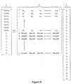
- FIG. 1 depicts a block diagram overview of a preferred system 100 for performing meshless noninvasive ECGI.
- the system 100 preferably comprises a plurality of electrodes 104 (mounted on strips 102, a vest, or in some other array) in communication with a signal acquisition and processing device 106.
- the electrodes 104 serve to sense a plurality of electrical potentials on a patient's body surface.
- the signal acquisition and processing device 106 operates to process this sensed data to a form suitable for digital processing, as is known in the art.
- the system 100 also comprises a geometry determining device 116 that serves to generate data that is indicative of the geometrical relationship between the electrodes 104 and one or more points of interest within the patient (e.g., the patient's epicardial cardiac surface).
- Processor 114 operates to (1) receive data from both the electrodes 104 (by way of the signal acquisition and processing device 106) and the geometry determining device 116 and (2) reconstruct epicardial cardiac surface potentials from the received data. The reconstructed epicardial potentials can then be used to provide, via the output device 118, electrograms, isochrones (activation maps), epicardial cardiac potential maps, or other data representations derived from the epicardial potentials (e.g., integral maps, recovery maps, activation-recovery interval maps, etc.).
- An example of a suitable processor 114 for the present invention is a conventional desktop or laptop computer, such as a 2.4 GHz laptop computer with a gigabyte of RAM.
- Output device 118 may be any device capable of effectively communicating the results of the reconstruction to a user, such as a display monitor and/or printer associated with the processor 114, as would be understood by those having ordinary skill in the art.
- the meshless ECGI technique described herein can readily be implemented in software and/or hardware for execution by one or more processors to compute epicardial cardiac surface potentials.
- the processor 114 and geometry determining device may be integrated into the same platform, such as a CT scanner, an MRI scanner, a bi-plane X-ray fluoroscopy apparatus, or an ultrasound echocardiography apparatus that has MFS ECGI processing capabilities built-in.
- Electrodes 104 are preferably arranged on a plurality of strips 102 that can be placed in position on the torso of a patient undergoing ECGI. Alternatively, a vest arrangement as shown in U.S. patent 6,772,004 and pending U.S. patent application 10/264,572 may also be used. As mentioned above, electrodes 104 measure the electrical potentials on the patient's torso. The electrodes 104 that are used are preferably electrodes that are visible in the imaging modality used by the geometry determining device 116. Otherwise, it is preferred that appropriate markers be placed on the electrodes to render them visible in the images produced by the geometry determining device 116.
- the total number of electrodes 104, the number of electrodes 104 per strip 102, the number of electrode strips 102, and the placement of the electrode strips 102 on the patient can be variable according to the needs of a practitioner of the present invention. However, it is preferred that as much of the patient's torso (front, back, and sides) be covered by electrodes 104 as possible.
- the total number N of electrodes 104 could range from 120 to 250. However, the value of N may be more or less than a value within this range, as would be understood by a person having ordinary skill in the art. However, the inventors herein believe that the use of too few electrodes will reduce the accuracy of the reconstructed epicardial cardiac surface potentials.
- the electrodes can be wet electrodes or dry electrodes, as would be understood by those having ordinary skill in the art. By avoiding the use of gels, short circuiting risks arising from a high concentration of electrodes can be reduced.
- An example of a suitable type of electrode to obtain body surface potentials is a silver/silver chloride (Ag/AgCl) electrode.
- Ag/AgCl silver/silver chloride
- other types of electrodes such as carbon electrodes can also be used.
- CT is used as the imaging modality for the geometry determining device, then it is preferred that CT markers be disposed on the carbon electrodes to render them visible in the CT images.
- the signal acquisition and processing device 106 is preferably a multichannel device that operates to receive the sensed electrical potentials from the electrodes 104, process that data, and supply it to processor 114. Practitioners of the present invention may select a commercially-available system to use as the signal acquisition and processing device 106.
- the Active Two system that is available from BioSemi of WG-Plein 129, 10545C, Amsterdam, Netherlands, which is a 256-channel, DC amplifier, 24 bit resolution biopotential measurement system, may serve as device 106.
- the Active Two biopotential measurement system includes an analog-to-digital converter (ADC) that receives electrode data from electrodes 104, a power source (battery and charger), a USB2 receiver that receives the digital output from the ADC via a fiber optic connection and provides the digital electrode data to acquisition software resident on processor 114 via a USB2 connection.
- ADC analog-to-digital converter
- the analog input box that is also part of the Active Two system may be omitted from the practice of the preferred embodiment.
- custom-designed signal acquisition and processing device 106 can also be used, such as the one described in prior U.S. patent 6,772,004 and pending U.S. patent application 10/264,572 .
- the geometry determining device 116 may take a variety of forms, as described in prior U.S. patent 6,772,004 and pending U.S. patent applications 10/264,572 and 10/317,953 , including x-ray, ultrasound, computed tomography (CT) and magnetic resonance imaging (MRI).
- CT computed tomography
- MRI magnetic resonance imaging
- the geometry determining device 116 may take the form of a CT scanner or MRI device 200.
- CT scanner/MRI device 200 is used to generate data, or images, to determine torso geometry and, consequently, body surface electrode positions as well as an epicardial envelope surrounding the heart.
- the epicardial envelope is a suitable estimate of the epicardial cardiac surface itself, which could also be determined. It should also be recognized that locating the epicardial envelope or surface necessarily involves location of the heart. As a further example, as shown in Figure 2(b) and described in greater detail in prior U.S. patent 6,772,004 and pending U.S. patent applications 10/264,572 and 10/317,953 , the geometry determining device 116 may also take the form of a bi-plane x-ray machine 202 and a digitizer 204.
- Figure 3 depicts a high level view of the noninvasive ECGI process.
- a geometry determining device 116 such as a CT scanner
- these measured ECG potentials can be processed to generate body surface potential data (step e)
- the software components of the preferred embodiment preferably operate to combine and process the body surface potential data and the heart-torso geometry data to reconstruct estimates of the epicardial cardiac surface potentials. These reconstructed epicardial cardiac surface potentials can in turn be processed at step g to generate appropriate epicardial cardiac surface potential maps, epicardial cardiac surface electrograms, and epicardial cardiac surface isochrones.
- FIG. 4 depicts the preferred flow for the meshless noninvasive ECGI of the present invention in greater detail.
- Signal acquisition and processing as described in connection with device 106 is performed on the sensed body surface potential data 400 from electrodes 104 to generate a 1xN vector V T of torso surface potentials, wherein N preferably represents the total number of electrodes 104 used by system 100 such that V T (i) represents the torso surface potential that was measured by a particular electrode 104(i).
- V T serves as a body surface potential map (BPSM). It is desired to reconstruct an epicardial cardiac surface potential map V E from V T using geometry data 402 that identifies the geometrical relationship between the torso surface, torso electrodes, and epicardial cardiac surface.
- BPSM body surface potential map
- This geometry data can be obtained from geometry determining device 116 as described in connection with Figures 1 and 2 . It should be recognized that in a clinical setting, the geometry data 402 would be generated by the geometry determining device 116; however, it should also be noted that when executing the MFS ECGI technique for testing and/or validation purposes, the geometry data 402 may be known parameters, such as those associated with geometric spheres and torso tanks (used in testing), that are simply input to the system.
- the geometry data can be a plurality of CT slices from which the patient's torso surface, the torso electrodes disposed on the patient's torso surface, and epicardial cardiac surface can be identified. Furthermore, based on the known slice thickness and scan parameters, the location of any given point on each slice can be determined in a three-dimensional (3D) coordinate space, and thus the geometrical relationship between any two points can also be determined in the 3D coordinate space.
- 3D three-dimensional
- Figure 5(a) depicts an exemplary CT scan in which the patient's torso surface 500 and epicardial cardiac surface 502 are visible.
- MFS Method of Fundamental Solution
- 2D two-dimensional
- N torso electrodes or torso nodes
- TN 1 through TN N are Visible in the image of Figure 5(a) .
- N equals 8.
- this value of N is exemplary only and chosen for simplicity in connection with explaining the principles of the preferred embodiment of the present invention. As previously explained, in practice, it is preferred that much larger values of N be used.
- Each torso node TN i corresponds to the location where an electrical potential of the patient's torso surface 500 has been measured.
- the goal of the preferred embodiment is to translate the potential measurements at the torso nodes to nodes located on the epicardial envelope.
- the torso node measurements are translated to nodes on the epicardial cardiac surface 502.
- the locations of the nodes on the epicardial cardiac surface 502 (referred to herein as "epicardial nodes" - wherein “epicardial nodes” refers to the nodes that are defined on the epicardial cardiac surface specifically or on the epicardial envelope) should first be determined.
- Figure 5(b) depicts a plurality of epicardial nodes that are located on the patient's epicardial cardiac surface 502. If the torso node measurements are being translated to nodes on the epicardial envelope other than the epicardial cardiac surface 502, then the epicardial nodes will be located on the particular surface of interest. Because the heart is clearly visible in the CT slices, any of a variety of techniques can be used to identify the epicardial cardiac surface 502. For example, commercially-available or custom-designed medical image visualization and segmentation software, such as the well-known Amira 3D visualization software package, can be used to identify, segment, and label the heart and heart surface 502 in the CT slices. Segmentation can be performed manually or automatically by known algorithms in the art.
- each epicardial node either a manual or automatic technique can be used to place a plurality M of ENs on the epicardial cardiac surface 502.
- a manual technique a user manually places the ENs at user-selected points along the epicardial cardiac surface 502.
- an algorithm automatically distributes the ENs along the epicardial cardiac surface 502. It is worth noting that accuracy in node placement is important because any error in determining node position can cause computational error during the inverse computation described below.
- the value of M can vary as a design choice by a practitioner of the present invention. However, it is preferred that a sufficient number of ENs be placed on surface 502 such that the MFS technique described herein exhibits a desired degree of resolution.
- M is 100 or more.
- these M ENs are evenly distributed over the epicardial cardiac surface 502, but this need not be the case. For example, in some instances it may be desirable to obtain high spatial resolution reconstruction in a certain area of the heart, in which case a practitioner of the present invention may choose to concentrate more ENs in that area than in other areas.
- a plurality of source nodes are configured. These source nodes are "virtual" nodes that are placed to define two surfaces - one that is outside the torso surface 500 and one that is inside the epicardial cardiac surface 502. The shape of each of these surfaces can be arbitrary so long as the outer surface remains outside the torso surface 500 and the inner surface remains inside the epicardial cardiac surface 502.
- Two general approaches may be used when configuring the source nodes: (1) a static configuration where the source nodes that define the fictitious boundaries are placed at fixed and pre-selected locations, and (2) a dynamic configuration where the locations of the source nodes that define the fictitious boundaries are determined dynamically by a complex nonlinear optimization procedure. Because of the complex and time-consuming nature of the nonlinear optimization procedure, dynamic configuration of source nodes is not preferred. Instead, it is preferred that a static configuration be used.
- a preferred static configuration technique is a technique wherein the source nodes are placed at locations parallel to the torso surface (some distance outward therefrom) and epicardial cardiac surface (some distance inward therefrom).
- the source nodes are defined such that (1) the outer surface source nodes are placed some fixed distance outward from each torso node along the rays extending from C 0 through each of the torso nodes, and (2) the inner surface source nodes are placed some fixed distance inward from each epicardial node along the rays extending from C 0 through each of the epicardial nodes, wherein C 0 represents the geometric center of the heart.
- C 0 can be readily determined by conventional segmentation software as previously described.
- the fixed distance that is used for source node placement can be variable as a design choice for a practitioner of the present invention.
- a ratio of 1.2:1 can be used for configuring source nodes from the torso nodes and a ratio of 0.8:1 can be used for configuring source nodes for the epicardial nodes.
- each source node that defines the fictitious surface outside the torso surface is inflated at a 1.2:1 ratio
- the source node corresponding to that torso node would be located along a ray extending from C 0 through that torso node at a location 1.2 units of measurement from C 0 .
- each source node that defines the fictitious surface inside the epicardial cardiac surface is deflated at a 0.8:1 ratio
- the source node corresponding to that epicardial node would be located along a ray extending from C 0 through that epicardial node at a location 0.8 units of measurement from C 0 .
- Figure 5(c) depicts such a placement of source nodes SN 1 through SN 24 .
- N TNs and M ENs have been defined
- P the total number of source nodes will be N+M in the preferred embodiment.
- N 8 and M equals 16
- P equals 24.
- Source nodes SN 1 through SN 8 define an outer surface wherein SN 1 is some fixed distance outward from TN 1 along a ray extending from C 0 through TN 1 , wherein SN 2 is that fixed distance outward from TN 2 along a ray extending from C 0 through TN 2 , and so on.
- Source nodes SN 9 through SN 24 define an inner surface wherein SN 9 is some fixed distance inward from EN 1 along a ray extending from C 0 through EN 1 , wherein SN 10 is that fixed distance inward from EN 2 along a ray extending from C 0 through EN 10 , and so on.
- each source node SN i in the 3D coordinate space of the patient's torso are known, thereby making distance determinations between (1) each source node and each torso node and (2) each source node and each epicardial node easy to calculate.
- V T A ⁇ ⁇
- A is a 2NxP+1 matrix
- N represents the total number of torso nodes
- P represents the total number of source nodes.
- Figure 5(d) depicts various distances r from torso node TN 1 to exemplary source nodes (in this example, SN 1 , SN 2 , and SNio). For ease of reference, Figure 5(d) does not depict each distance r from each torso node to each source node, but a person having ordinary skill in the art would readily understand from Figure 5(d) how each value of r would be determined.
- the values d(a j,k )/dn in matrix A represent the derivatives of each a j,k term relative to the normal n defined by the torso surface 500 at the applicable torso node.
- Figure 5(e) illustrates the relationship between r j,k and normal n for an exemplary torso node TN(x).
- the normal to the torso surface 500 at given torso node TN(x) is defined as the perpendicular to the torso surface tangent at that torso node TN(x).
- d(a x,k )/dn terms for the row in A corresponding to torso node TN(x) will be computed from the normal to the torso surface 500 at TN(x), as shown in Figure 5(e) .
- ⁇ is an ill-posed problem as small perturbations in the data (e.g., potential measurement noise and/or geometrical inaccuracy) can cause large unbounded errors.
- a variety of mathematical schemes that are known in the art can be used. Two schemes that are believed to provide effective results are Tikhonov zero order regularization and the Generalized Minimal Residual (GMRes) method. These techniques are described in U.S. Patent No. 6,772,004 and pending U.S. patent application 10/264,572 .
- a forward computation 416 can be used to determine the epicardial cardiac surface potentials V E .
- a transfer matrix B must first be computed.
- B is a MxP+1 matrix
- M represents the total number of epicardial nodes
- P represents the total number of source nodes.
- the entries in matrix B are all known, which allows for a straightforward calculation of V E from B and ⁇ .
- V E (EN i ) within V E will represent an estimation of the epicardial cardiac surface potential at the location on the epicardium defined by EN i .
- V E or from a plurality of V E 's calculated from a plurality of successively measured V T 's, as may be appropriate), persons having ordinary skill in the art can readily produce a variety of potential maps, electrograms, isochrone maps, recovery maps, integral maps, and activation-recovery interval maps of the patient's epicardial cardiac surface at step 418.
- V E can be computed from V T without requiring a mesh of the torso or heart surfaces, thereby (among other advantages) greatly improving the speed of calculation for V E . Additional details about the MFS technique are included herewith in Appendix A.
- the reconstructed epicardial cardiac surface potentials V E were verified using benchmark data derived from a human-shaped torso-tank, the details of which are described in U.S. patent 6,772,004 . Additionally, data from experimentation using the torso tank allowed for comparisons to be made between the ECGI technique using MFS, the ECGI technique using BEM, and directly measured epicardial potentials.
- Focal sites of initiation of arrhythmogenic activity can result from abnormal automaticity, triggered activity, or micro-reentry. Because the focus is usually confined to a small region of the myocardium, it can be simulated by pacing the myocardium at a single site. Locating the ectopic focus is important for activities such as diagnosis and guiding an interventional therapeutic procedure (e.g., ablation).
- an interventional therapeutic procedure e.g., ablation
- Figure 9 shows electric potential maps 25 ms after pacing from a single site; the pacing site being marked by an asterisk.
- the top row of Figure 9 shows directly (i.e., invasively) measured heart surface potentials.
- the middle row shows heart surface potentials that were reconstructed using the MFS ECGI technique of the present invention.
- the bottom row shows heart surface potentials that were reconstructed using the prior BEM ECGI technique.
- the pacing site reconstructed by MFS ECGI is located only about 4 mm from its measured location, at the center of the potential minimum (blue). As can be seen, the potentials reconstructed via MFS ECGI show a high level of correspondence with the directly measured potentials.
- the pacing site reconstructed by BEM ECGI is located about 6 mm from its measured location. Additional examples of the improved accuracy of MFS ECGI relative to BEM ECGI are shown in Figure 9 via the higher correlation coefficient (CC) score and the lower relative error (RE) score. Moreover, not only do these results show that MFS ECGI is more accurate than BEM ECGI, but these results further confirm that MFS ECGI is considerably faster than BEM ECGI - the computation time per frame (CT) for MFS ECGI in this experiment is shown to be 0.2 seconds (versus 52 seconds for BEM ECGI). Appendix B describes how these CC and RE values were computed.
- CT computation time per frame
- electrograms can be formed from heart surface potential maps by developing such maps over successive time frames and then organizing the time series of maps by epicardial location.
- Figures 10(A)-(D) show various electrograms derived in this manner.
- Figure 10(A) shows four views of the epicardial cardiac surface. The numbers 1-9 in the boxes shown in Figure 10(A) identify the locations of nine electrodes whose measured electrograms and MFS ECGI-reconstructed electrograms are displayed in Figures 10(B)-(D) .
- Sites 1-3 are relatively close to the pacing site; sites 4-6 are relatively away from the pacing site; and sites 7-9 are relatively far away from the pacing site.
- Figure 10(B) depicts the monophasic negative (Q wave) electrograms from sites 1, 2 and 3 from both direct measurements and MFS ECGI reconstruction.
- Figure 10(C) depicts the biphasic electrograms from sites 4, 5, and 6 from both direct measurements and MFS ECGI reconstruction.
- Figure 10(D) depicts the monophasic positive (R wave) electrograms from sites 7, 8, and 9 from both direct measurements and MFS ECGI reconstruction.
- the displayed CC value in each MFS ECGI electrogram indicates the level of similarity between the MFS ECGI reconstructed electrograms and the directly measured electrograms. As can be seen, there is a high degree of correlation between the two.
- isochrones for either measured or reconstructed epicardial cardiac surface potential data can be computed by taking the time of the epicardial activity at a given location as the time of maximum negative dV/dt of the temporal electrogram (which can be referred to as "intrinsic deflection") at that location.
- Isochrones provide a faithful and direct depiction of the epicardial activation sequence, which includes potential spatial non-uniformities of activation spread (e.g., regions of sparse or crowded isochrones depicting fast or slow speed respectively).
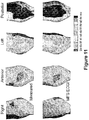
- Figure 11 provides a comparison of heart surface isochrone maps developed from measured potentials (the top row of Figure 11 ) and heart surface isochrone maps developed from potentials that have been reconstructed using MFS ECGI. As can be seen, the regions of earliest activation (shown in dark blue) are reproduced accurately in the MFS ECGI computed isochrone maps, as is the entire sequence of epicardial activation.
- Figure 10(B) depicts the monophasic negative (Q wave) electrograms from sites 1, 2 and 3 from both direct measurements and MFS ECGI reconstruction.
- Figure 10(C) depicts the biphasic electrograms from sites 4, 5, and 6 from both direct measurements and MFS ECGI reconstruction.
- Figure 10(D) depicts the monophasic positive (R wave) electrograms from sites 7, 8, and 9 from both direct measurements and MFS ECGI reconstruction.
- the displayed CC value in each MFS ECGI electrogram indicates the level of similarity between the MFS ECGI reconstructed electrograms and the directly measured electrograms. As can be seen, there is a high degree of correlation between the two.
- isochrones for either measured or reconstructed epicardial cardiac surface potential data can be computed by taking the time of the epicardial activity at a given location as the time of maximum negative dV/dt of the temporal electrogram (which can be referred to as "intrinsic deflection") at that location.
- Isochrones provide a faithful and direct depiction of the epicardial activation sequence, which includes potential spatial non-uniformities of activation spread (e.g., regions of sparse or crowded isochrones depicting fast or slow speed respectively).
- Figure 11 provides a comparison of heart surface isochrone maps developed from measured potentials (the top row of Figure 11 ) and heart surface isochrone maps developed from potentials that have been reconstructed using MFS ECGI. As can be seen, the regions of earliest activation (shown in dark blue) are reproduced accurately in the MFS ECGI computed isochrone maps, as is the entire sequence of epicardial activation.
- Panel A of Figure 12 depicts heart surface potential maps 25 ms after right ventricular pacing from a single site (indicated by the white asterisk) in a human subject using both BEM ECGI and MFS ECGI, wherein the MFS ECGI reconstruction is shown to avoid mesh-related artifacts (the fragmentation of the minimum blue shown in the BEM ECGI panel).
- Panel B depicts these maps during repolarization. Avoidance of the mesh-related artifacts allows the pacing site to be more accurately located; wherein the error in locating the pacing site was 14 mm using BEM ECGI versus 7 mm using MFS ECGI.
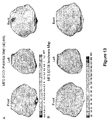
- FIG. 13 depicts human heart surface isochrone maps and potential maps, using MFS ECGI, for pacing from both a right ventricle (RV) site and a left ventricle (LV) (indicated by the asterisks).
- RV right ventricle
- LV left ventricle
- Figure 13 demonstrates that in a CRT study, both LV and RV pacing sites can be accurately located using MFS ECGI. Experiments have shown that, with MFS ECGI, the location errors for the RV pacing site and the LV pacing site are 5.2 mm and 7.4 mm respectively.
- FIG. 14 shows the normal atrial activation isochrones computed using MFS ECGI reconstructed potentials for a healthy volunteer. As can be seen, earliest activation starts in the right atrium (RA), near the anatomical location of the sinoatrial node (SA node). From the SA node, the impulse propagates to the left atrium (LA) and the rest of the RA.
- RA right atrium
- SA node sinoatrial node
- LAA LA appendage
- SVC in Figure 14 refers to the superior vena cava and the abbreviation PV refers to the pulmonary veins.
- MFS ECGI noninvasively reconstructed atrial isochrone produced by MFS ECGI is highly consistent with the invasive measurements as described in Durrer D. et al., Total excitation of the isolated human heart, Circulation, 1970, 41: 899-91 2 .
- meshless techniques other than the MFS technique described herein can be used to practice meshless noninvasive ECGI in accordance with the present invention; these alternative meshless techniques include but are not limited to other implementations of MFS (such as MFS implementations using dipoles or multi-poles of higher order), the Radial Basis Function (RBF), the Boundary Knot (BKM) method, the Meshless Local Petrov-Galerkin (MLPG) method, the Trefftz method, the Element Free Galerkin (ELG) method, the Partition of Unity method (PUM, including PUFEM, GFEM and XFEM), and the Meshless Finite Element method (MFEM).
- MFS Radial Basis Function
- BKM Boundary Knot
- MLPG Meshless Local Petrov-Galerkin
- EEG Element Free Galerkin
- PUM Partition of Unity method
- PUM including PUFEM, GFEM and XFEM
- MFEM Meshless Finite Element method
- MFS approximates the solution of a PDE by a linear combination of fundamental solutions of the governing partial differential operator. See, Fairweather G, Karageorghis A. The method of fundamental solutions for elliptic boundary value problems. Adv Comput Math 9(1-2): 69-95, 1998 .
- the governing partial differential operator is the Laplacian operator ⁇ 2 .
- the formulation of MFS for a ⁇ 2 boundary value problem is described below.
- MFS has evolved from traditional boundary integral methods.
- the following example is used to describe the theoretical formulation of MFS for a Laplacian operator.
- ⁇ 2 is the Laplace differential operator with a known fundamental solution f ( r ) in 3D space
- b ( x ) is the Essential boundary condition.
- u x ⁇ ⁇ ⁇ f ⁇ x ⁇ y ⁇ ⁇ n e y dy , x ⁇ ⁇ , y ⁇ ⁇
- n is the outward pointing normal at point y
- e ( y ) is the unknown density function
- the analytic integral representation of (a10) means that there are infinite number of source density points on ⁇ . Therefore, in order to apply numerical solution method, it is necessary to discretize e ( y ) .
- RE relative error
- CC correlation coefficients
- pacing site localization errors are also provided for both torso-tank and human reconstructions.
- the computed pacing site location was estimated by the center of an ellipse that best fits the quasi-elliptical negative potential region that develops around the pacing site. The earliest time frame after pacing, for which such pattern was present, was used for this purpose. Pacing sites could also be determined from isochrone maps as the sites of earliest activation.
- ECGI In addition to CC RE, clinical application of ECGI will benefit from computational efficiency that reconstructs epicardial potentials in close to real time (near real time). Although regularization procedures (e.g. Tikhonov regularization with the regularization parameter selected by CRESO, and so on) can be done close to real-time, forming the coefficient matrix usually still takes more than 1 minute in BEM ECGI. Ideally if the coefficient matrix can also be formed within less time (e.g. less than one second), ECGI would have much better chance to be used in the interactive applications during clinical interventions.
- regularization procedures e.g. Tikhonov regularization with the regularization parameter selected by CRESO, and so on
- forming the coefficient matrix usually still takes more than 1 minute in BEM ECGI. Ideally if the coefficient matrix can also be formed within less time (e.g. less than one second), ECGI would have much better chance to be used in the interactive applications during clinical interventions.
- CT Computation Time of forming coefficient matrix (in seconds)
- CTR CT of BEM ECGI CT of MFS ECGI
- CT and CRT were computed on a laptop with Pentium Mobile 1.7GHz and 1G RAM. Qualitative evaluations of automatic between MFS ECGI and BEM ECGI were also done by comparing the working procedure of MFS ECGI and BEM ECGI in specific cases.
Claims (6)
- Système non invasif (100) pour déterminer l'activité électrique d'un cœur d'un être vivant,
le système comprenant :un processeur (114) ;un système de réseau d'électrodes (102) en communication avec le processeur (114) pour
mesurer de manière non invasive des potentiels électriques à une pluralité d'emplacements sur le torse d'un être vivant par l'intermédiaire d'une pluralité d'électrodes (104) appliquées sur le torse et fournissant un ensemble de potentiels électriques à la surface du corps ;un dispositif de détermination de géométrie (116) en communication avec le processeur, le dispositif de détermination de géométrie étant configuré pour générer des données de géométrie indiquant une relation géométrique entre une pluralité d'emplacements correspondant aux nœuds où les potentiels électriques de surface du corps ont été mesurés et les nœuds sur une enveloppe cardiaque épicardique du cœur ;caractérisé en ce que le processeur (114) est configuré pour :recevoir l'ensemble de potentiels électriques de surface du corps et les données de géométrie ;déterminer une pluralité de nœuds épicardiques définissant des emplacements sur l'enveloppe cardiaque épicardique ;déterminer une pluralité de nœuds sources externes qui définissent une pluralité d'emplacements le long d'une surface qui est à l'extérieur du torse de l'être vivant ;déterminer une pluralité de nœuds sources internes qui définissent une pluralité d'emplacements le long d'une surface à l'intérieur de la surface cardiaque épicardique ; et
utiliser une méthode des solutions fondamentales (MFS) pour reconstruire les potentiels de surface cardiaques épicardiques pour la pluralité de nœuds cardiaques épicardiques à partir de l'ensemble des potentiels électriques de surface corporelle, sur la base des données géométriques, en :(1) déterminant une matrice de coefficients A (408) qui relie chaque emplacement d'électrode à chaque emplacement de nœud source, (2) effectuant un calcul inverse sur A (410) et les potentiels électriques de surface corporelle mesurés de manière non invasive pour calculer une pluralité de nœuds source interne et externe des coefficients, (3) déterminant une matrice de coefficients B (414) reliant chaque emplacement de nœud épicardique à chaque emplacement de nœud source interne et externe, et (4) effectuant un calcul direct (416) en utilisant B et les coefficients de nœud source pour calculer les potentiels électriques de surface cardiaque épicardique reconstruits. - Système selon la revendication 1, dans lequel le processeur est en outre configuré pour déterminer statiquement les nœuds sources interne et externe (1) en définissant chaque nœud source externe de telle sorte qu'il est situé à une distance prédéterminée vers l'extérieur à partir d'un emplacement d'électrode correspondant sur un rayon s'étendant à partir d'un centre calculé de l'enveloppe cardiaque épicardique à travers l'emplacement d'électrode correspondant, et (2) définissant chaque nœud source interne de telle sorte qu'il se trouve à une distance prédéterminée vers l'intérieur d'un emplacement de nœud épicardique correspondant sur un rayon s'étendant à partir du centre calculé de l'enveloppe cardiaque épicardique à travers l'emplacement du nœud épicardique correspondant.
- Système selon la revendication 1 ou 2, dans lequel le processeur est en outre configuré pour générer une carte de potentiel de surface cardiaque épicardique à partir de l'ensemble des potentiels électriques de surface cardiaque épicardique calculés.
- Système selon l'une quelconque des revendications 1 ou 2, dans lequel le processeur est en outre configuré pour calculer une pluralité d'ensembles des potentiels électriques de surface cardiaque épicardiques sur une durée à partir d'une pluralité de potentiels électriques de surface corporelle successivement mesurés de manière non invasive.
- Système selon la revendication 4, dans lequel le processeur est en outre configuré pour générer au moins un élément sélectionné dans le groupe constitué d'une pluralité d'électrogrammes et d'une isochrone à partir des ensembles de potentiels électriques de surface cardiaque épicardique calculés.
- Système selon la revendication 4, dans lequel le processeur est en outre configuré pour générer, à partir des ensembles de potentiels électriques de surface cardiaque épicardique calculés, au moins un élément choisi dans le groupe constitué par une carte de récupération, une carte intégrale et une carte d'intervalle activation/récupération.
Priority Applications (1)
| Application Number | Priority Date | Filing Date | Title |
|---|---|---|---|
| EP11010196.1A EP2436309B1 (fr) | 2005-07-22 | 2006-07-21 | Image électro-cardiographique non invasive |
Applications Claiming Priority (2)
| Application Number | Priority Date | Filing Date | Title |
|---|---|---|---|
| US70162605P | 2005-07-22 | 2005-07-22 | |
| PCT/US2006/028287 WO2007013994A2 (fr) | 2005-07-22 | 2006-07-21 | Systeme et procede d'imagerie electrocardiographique non invasive |
Related Child Applications (2)
| Application Number | Title | Priority Date | Filing Date |
|---|---|---|---|
| EP11010196.1A Division-Into EP2436309B1 (fr) | 2005-07-22 | 2006-07-21 | Image électro-cardiographique non invasive |
| EP11010196.1A Division EP2436309B1 (fr) | 2005-07-22 | 2006-07-21 | Image électro-cardiographique non invasive |
Publications (3)
| Publication Number | Publication Date |
|---|---|
| EP1906821A2 EP1906821A2 (fr) | 2008-04-09 |
| EP1906821A4 EP1906821A4 (fr) | 2009-12-30 |
| EP1906821B1 true EP1906821B1 (fr) | 2020-01-15 |
Family
ID=37683807
Family Applications (2)
| Application Number | Title | Priority Date | Filing Date |
|---|---|---|---|
| EP11010196.1A Active EP2436309B1 (fr) | 2005-07-22 | 2006-07-21 | Image électro-cardiographique non invasive |
| EP06800185.8A Active EP1906821B1 (fr) | 2005-07-22 | 2006-07-21 | Système d'imagerie electrocardiographique non invasive (ecgi) |
Family Applications Before (1)
| Application Number | Title | Priority Date | Filing Date |
|---|---|---|---|
| EP11010196.1A Active EP2436309B1 (fr) | 2005-07-22 | 2006-07-21 | Image électro-cardiographique non invasive |
Country Status (4)
| Country | Link |
|---|---|
| US (1) | US7983743B2 (fr) |
| EP (2) | EP2436309B1 (fr) |
| CA (1) | CA2616263C (fr) |
| WO (1) | WO2007013994A2 (fr) |
Families Citing this family (79)
| Publication number | Priority date | Publication date | Assignee | Title |
|---|---|---|---|---|
| GB0710963D0 (en) | 2007-06-08 | 2007-07-18 | Psi Heartsignals Global Ltd | Methods of measurement of drug induced changes in cardiac ion channel function and associated apparatus |
| DE102008032343A1 (de) | 2008-07-09 | 2010-01-14 | Siemens Aktiengesellschaft | Verfahren zur Ermittlung einer Positionierinformation für EKG-Elektroden während einer Untersuchung mit einer Magnetresonanzeinrichtung und Magnetresonanzeinrichtung |
| EP3536236B1 (fr) | 2008-08-11 | 2023-11-22 | Washington University in St. Louis | Systèmes et procédés pour l'imagerie électrocardiographique (ecgi) sur site et en temps réel |
| US9265951B2 (en) | 2010-02-12 | 2016-02-23 | The Brigham And Women's Hospital | System and method for automated adjustment of cardiac resynchronization therapy control parameters |
| US9078573B2 (en) * | 2010-11-03 | 2015-07-14 | Cardioinsight Technologies, Inc. | System and methods for assessing heart function |
| EP2632330B1 (fr) | 2010-12-30 | 2020-05-20 | St. Jude Medical, Atrial Fibrillation Division, Inc. | Système de cartographie électrophysiologique faisant appel à des électrodes externes |
| US8972228B2 (en) | 2011-05-03 | 2015-03-03 | Medtronic, Inc. | Assessing intra-cardiac activation patterns |
| JP2014523321A (ja) | 2011-07-05 | 2014-09-11 | カーディオインサイト テクノロジーズ インコーポレイテッド | 患者の治療を容易にするシステムおよび方法 |
| JP6259762B2 (ja) | 2011-10-12 | 2018-01-10 | カーディオインサイト テクノロジーズ インコーポレイテッド | 空間的に関連する電気情報用の検知ゾーン |
| EP2945533A4 (fr) | 2013-01-17 | 2016-10-05 | Cardioinsight Technologies Inc | Cartographie physiologique multiparamètres |
| US10049771B2 (en) | 2013-03-15 | 2018-08-14 | St. Jude Medical, Atrial Fibrillation Division, Inc. | Laplacian and Tikhonov regularization for voltage mapping with a medical device |
| US9278219B2 (en) | 2013-03-15 | 2016-03-08 | Medtronic, Inc. | Closed loop optimization of control parameters during cardiac pacing |
| US9931048B2 (en) | 2013-04-30 | 2018-04-03 | Medtronic, Inc. | Systems, methods, and interfaces for identifying effective electrodes |
| US10064567B2 (en) | 2013-04-30 | 2018-09-04 | Medtronic, Inc. | Systems, methods, and interfaces for identifying optimal electrical vectors |
| US9877789B2 (en) | 2013-06-12 | 2018-01-30 | Medtronic, Inc. | Implantable electrode location selection |
| US9486151B2 (en) | 2013-06-12 | 2016-11-08 | Medtronic, Inc. | Metrics of electrical dyssynchrony and electrical activation patterns from surface ECG electrodes |
| US10251555B2 (en) | 2013-06-12 | 2019-04-09 | Medtronic, Inc. | Implantable electrode location selection |
| US9278220B2 (en) | 2013-07-23 | 2016-03-08 | Medtronic, Inc. | Identification of healthy versus unhealthy substrate for pacing from a multipolar lead |
| US9282907B2 (en) | 2013-07-23 | 2016-03-15 | Medtronic, Inc. | Identification of healthy versus unhealthy substrate for pacing from a multipolar lead |
| US9265954B2 (en) | 2013-07-26 | 2016-02-23 | Medtronic, Inc. | Method and system for improved estimation of time of left ventricular pacing with respect to intrinsic right ventricular activation in cardiac resynchronization therapy |
| US9265955B2 (en) | 2013-07-26 | 2016-02-23 | Medtronic, Inc. | Method and system for improved estimation of time of left ventricular pacing with respect to intrinsic right ventricular activation in cardiac resynchronization therapy |
| US11103174B2 (en) * | 2013-11-13 | 2021-08-31 | Biosense Webster (Israel) Ltd. | Reverse ECG mapping |
| US9320446B2 (en) | 2013-12-09 | 2016-04-26 | Medtronic, Inc. | Bioelectric sensor device and methods |
| US9986928B2 (en) | 2013-12-09 | 2018-06-05 | Medtronic, Inc. | Noninvasive cardiac therapy evaluation |
| CN106255455B (zh) | 2013-12-12 | 2019-08-16 | 科迪影技术股份有限公司 | 采用补充信息改善反演问题的解 |
| US9776009B2 (en) | 2014-03-20 | 2017-10-03 | Medtronic, Inc. | Non-invasive detection of phrenic nerve stimulation |
| US9591982B2 (en) | 2014-07-31 | 2017-03-14 | Medtronic, Inc. | Systems and methods for evaluating cardiac therapy |
| US9764143B2 (en) | 2014-08-15 | 2017-09-19 | Medtronic, Inc. | Systems and methods for configuration of interventricular interval |
| US9586050B2 (en) | 2014-08-15 | 2017-03-07 | Medtronic, Inc. | Systems and methods for configuration of atrioventricular interval |
| US9586052B2 (en) | 2014-08-15 | 2017-03-07 | Medtronic, Inc. | Systems and methods for evaluating cardiac therapy |
| US9707400B2 (en) | 2014-08-15 | 2017-07-18 | Medtronic, Inc. | Systems, methods, and interfaces for configuring cardiac therapy |
| US11253178B2 (en) | 2015-01-29 | 2022-02-22 | Medtronic, Inc. | Noninvasive assessment of cardiac resynchronization therapy |
| US10299692B2 (en) | 2015-05-13 | 2019-05-28 | Ep Solutions, S.A. | Systems, components, devices and methods for cardiac mapping using numerical reconstruction of cardiac action potentials |
| CN107666856B (zh) * | 2015-06-02 | 2021-03-09 | 科迪影技术股份有限公司 | 提供几何形状信息的磁感测 |
| US10602957B2 (en) | 2015-06-30 | 2020-03-31 | Varuna Biomedical Corporation | Systems and methods for detecting and visualizing biofields with nuclear magnetic resonance imaging and QED quantum coherent fluid immersion |
| GB201521477D0 (en) | 2015-12-04 | 2016-01-20 | Imp Innovations Ltd | Methods and apparatus for analysing changes in the electrical activity of a patient's heart in different states |
| US10780279B2 (en) | 2016-02-26 | 2020-09-22 | Medtronic, Inc. | Methods and systems of optimizing right ventricular only pacing for patients with respect to an atrial event and left ventricular event |
| US11219769B2 (en) | 2016-02-26 | 2022-01-11 | Medtronic, Inc. | Noninvasive methods and systems of determining the extent of tissue capture from cardiac pacing |
| EP3451904B1 (fr) | 2016-05-03 | 2023-12-20 | CardioInsight Technologies, Inc. | Détection de synchronisation de conduction |
| EP3451918B1 (fr) | 2016-05-03 | 2020-09-23 | CardioInsight Technologies, Inc. | Détection et analyse des électrogrammes |
| US10532213B2 (en) | 2017-03-03 | 2020-01-14 | Medtronic, Inc. | Criteria for determination of local tissue latency near pacing electrode |
| US10987517B2 (en) | 2017-03-15 | 2021-04-27 | Medtronic, Inc. | Detection of noise signals in cardiac signals |
| WO2018195052A1 (fr) * | 2017-04-18 | 2018-10-25 | Boston Scientific Scimed Inc. | Histogramme d'annotation pour signaux électrophysiologiques |
| US10456056B2 (en) | 2017-06-21 | 2019-10-29 | Biosense Webster (Israel) Ltd. | Combination torso vest to map cardiac electrophysiology |
| CN110891475B (zh) * | 2017-07-12 | 2023-04-11 | 科迪影技术股份有限公司 | 成像以确定电极几何形状 |
| WO2019023478A1 (fr) | 2017-07-28 | 2019-01-31 | Medtronic, Inc. | Sélection de révolution cardiaque |
| WO2019023472A1 (fr) | 2017-07-28 | 2019-01-31 | Medtronic, Inc. | Génération de temps d'activation |
| US10492705B2 (en) | 2017-12-22 | 2019-12-03 | Regents Of The University Of Minnesota | Anterior and posterior electrode signals |
| US10433746B2 (en) | 2017-12-22 | 2019-10-08 | Regents Of The University Of Minnesota | Systems and methods for anterior and posterior electrode signal analysis |
| US10786167B2 (en) | 2017-12-22 | 2020-09-29 | Medtronic, Inc. | Ectopic beat-compensated electrical heterogeneity information |
| US10799703B2 (en) | 2017-12-22 | 2020-10-13 | Medtronic, Inc. | Evaluation of his bundle pacing therapy |
| US11419539B2 (en) | 2017-12-22 | 2022-08-23 | Regents Of The University Of Minnesota | QRS onset and offset times and cycle selection using anterior and posterior electrode signals |
| US10617318B2 (en) | 2018-02-27 | 2020-04-14 | Medtronic, Inc. | Mapping electrical activity on a model heart |
| US10668290B2 (en) | 2018-03-01 | 2020-06-02 | Medtronic, Inc. | Delivery of pacing therapy by a cardiac pacing device |
| US10918870B2 (en) | 2018-03-07 | 2021-02-16 | Medtronic, Inc. | Atrial lead placement for treatment of atrial dyssynchrony |
| EP3764890A1 (fr) | 2018-03-15 | 2021-01-20 | CardioInsight Technologies, Inc. | Détection et localisation d'un déclenchement cardiaque rapide |
| US10780281B2 (en) | 2018-03-23 | 2020-09-22 | Medtronic, Inc. | Evaluation of ventricle from atrium pacing therapy |
| US11039776B2 (en) | 2018-03-23 | 2021-06-22 | Cardioinsight Technologies, Inc. | Determining bipolar electrical activity |
| US11285312B2 (en) | 2018-03-29 | 2022-03-29 | Medtronic, Inc. | Left ventricular assist device adjustment and evaluation |
| US11138792B2 (en) | 2018-04-02 | 2021-10-05 | Cardioinsight Technologies, Inc. | Multi-dimensional method of fundamental solutions for reconstruction of electrophysiological activity |
| US11304641B2 (en) | 2018-06-01 | 2022-04-19 | Medtronic, Inc. | Systems, methods, and interfaces for use in cardiac evaluation |
| US10940321B2 (en) | 2018-06-01 | 2021-03-09 | Medtronic, Inc. | Systems, methods, and interfaces for use in cardiac evaluation |
| WO2020106702A1 (fr) | 2018-11-19 | 2020-05-28 | Cardioinsight Technologies, Inc. | Variation totale de graphe pour ecgi |
| US11547858B2 (en) | 2019-03-29 | 2023-01-10 | Medtronic, Inc. | Systems, methods, and devices for adaptive cardiac therapy |
| US11697025B2 (en) | 2019-03-29 | 2023-07-11 | Medtronic, Inc. | Cardiac conduction system capture |
| US11497431B2 (en) | 2019-10-09 | 2022-11-15 | Medtronic, Inc. | Systems and methods for configuring cardiac therapy |
| US11642533B2 (en) | 2019-11-04 | 2023-05-09 | Medtronic, Inc. | Systems and methods for evaluating cardiac therapy |
| US11813464B2 (en) | 2020-07-31 | 2023-11-14 | Medtronic, Inc. | Cardiac conduction system evaluation |
| US20220160307A1 (en) | 2020-11-25 | 2022-05-26 | Cardioinsight Technologies, Inc. | Noise filtering for electrophysiological signals |
| US11691018B2 (en) | 2021-02-19 | 2023-07-04 | Cardioinsight Technologies Inc. | Using implantable medical devices to augment noninvasive cardiac mapping |
| WO2022192629A1 (fr) | 2021-03-12 | 2022-09-15 | Cardioinsight Technologies Inc. | Activation tardive de signaux cardiaques |
| WO2023014637A1 (fr) | 2021-08-02 | 2023-02-09 | Cardioinsight Technologies Inc. | Systèmes et procédés de cartographie électrocardiographique et d'identification de site cible |
| WO2023081594A1 (fr) | 2021-11-02 | 2023-05-11 | Cardioinsight Technologies Inc. | Surveillance et analyse de signaux électrophysiologiques invasifs et non invasifs |
| WO2023086446A1 (fr) | 2021-11-12 | 2023-05-19 | Cardioinsight Technologies Inc. | Imagerie électrocardiographique à l'aide d'électrodes à plaque |
| WO2023091570A1 (fr) | 2021-11-19 | 2023-05-25 | Cardioinsight Technologies Inc. | Déclencheurs automatisés pour assistance sur cas d'électrophysiologie |
| WO2023119137A1 (fr) | 2021-12-22 | 2023-06-29 | Cardioinsight Technologies Inc. | Cartographie automatisée et/ou traitement de signal en réponse à des caractéristiques de signal cardiaque |
| WO2023135475A1 (fr) | 2022-01-14 | 2023-07-20 | Cardioinsight Technologies Inc. | Cartographie cardiaque pour évaluer un impact d'interventions |
| WO2024011128A1 (fr) | 2022-07-05 | 2024-01-11 | Medtronic, Inc. | Guidage interventionnel |
| WO2024020340A1 (fr) | 2022-07-19 | 2024-01-25 | Cardioinsight Technologies Inc. | Élimination de signaux de champ lointain à partir d'informations d'électrophysiologie |
Citations (1)
| Publication number | Priority date | Publication date | Assignee | Title |
|---|---|---|---|---|
| US20030120163A1 (en) * | 1997-07-31 | 2003-06-26 | Yoram Rudy | System and methods for noninvasive electrocardiographic imaging (ECGI) using generalized minimum residual (GMRes) |
Family Cites Families (7)
| Publication number | Priority date | Publication date | Assignee | Title |
|---|---|---|---|---|
| US5146926A (en) | 1990-10-26 | 1992-09-15 | Massachusetts Institute Of Technology | Method and apparatus for imaging electrical activity in a biological system |
| IL98613A (en) * | 1991-06-25 | 1996-01-31 | Technion Res & Dev Foundation | Method and apparatus for analyzing the electrical activity of the heart |
| US5891045A (en) * | 1996-07-17 | 1999-04-06 | Cambridge Heart, Inc. | Method and system for obtaining a localized cardiac measure |
| US6975900B2 (en) | 1997-07-31 | 2005-12-13 | Case Western Reserve University | Systems and methods for determining a surface geometry |
| WO1999005962A1 (fr) | 1997-07-31 | 1999-02-11 | Case Western Reserve University | Systeme et procede d'imagerie electrocardiographique non vulnerant |
| US6718291B1 (en) * | 1999-07-02 | 2004-04-06 | Vadim Shapiro | Mesh-free method and system for modeling and analysis |
| US6856830B2 (en) * | 2001-07-19 | 2005-02-15 | Bin He | Method and apparatus of three dimension electrocardiographic imaging |
-
2006
- 2006-07-21 US US11/996,441 patent/US7983743B2/en active Active
- 2006-07-21 EP EP11010196.1A patent/EP2436309B1/fr active Active
- 2006-07-21 EP EP06800185.8A patent/EP1906821B1/fr active Active
- 2006-07-21 CA CA2616263A patent/CA2616263C/fr active Active
- 2006-07-21 WO PCT/US2006/028287 patent/WO2007013994A2/fr active Application Filing
Patent Citations (1)
| Publication number | Priority date | Publication date | Assignee | Title |
|---|---|---|---|---|
| US20030120163A1 (en) * | 1997-07-31 | 2003-06-26 | Yoram Rudy | System and methods for noninvasive electrocardiographic imaging (ECGI) using generalized minimum residual (GMRes) |
Also Published As
| Publication number | Publication date |
|---|---|
| CA2616263A1 (fr) | 2007-02-01 |
| EP1906821A2 (fr) | 2008-04-09 |
| CA2616263C (fr) | 2014-12-16 |
| WO2007013994A2 (fr) | 2007-02-01 |
| EP2436309A3 (fr) | 2014-03-12 |
| US7983743B2 (en) | 2011-07-19 |
| EP2436309A2 (fr) | 2012-04-04 |
| WO2007013994A3 (fr) | 2007-04-26 |
| EP1906821A4 (fr) | 2009-12-30 |
| EP2436309B1 (fr) | 2021-03-17 |
| US20090053102A2 (en) | 2009-02-26 |
Similar Documents
| Publication | Publication Date | Title |
|---|---|---|
| EP1906821B1 (fr) | Système d'imagerie electrocardiographique non invasive (ecgi) | |
| US8388547B2 (en) | Method of noninvasive electrophysiological study of the heart | |
| US6975900B2 (en) | Systems and methods for determining a surface geometry | |
| US9526434B2 (en) | Cardiac mapping with catheter shape information | |
| US20210219899A1 (en) | Systems And Methods For Noninvasive Spectral-Spatiotemporal Imaging of Cardiac Electrical Activity | |
| US7016719B2 (en) | System and methods for noninvasive electrocardiographic imaging (ECGI) using generalized minimum residual (GMRes) | |
| JP5281570B2 (ja) | カテーテルの移動と複数心拍の統合を含む非接触式心臓マッピング | |
| JP5628804B2 (ja) | オンサイトでリアルタイムの心電図イメージング(ecgi)のためのシステムおよび方法 | |
| US7957791B2 (en) | Multi-beat integration for cardiac mapping | |
| US10299692B2 (en) | Systems, components, devices and methods for cardiac mapping using numerical reconstruction of cardiac action potentials | |
| CN108324263B (zh) | 一种基于低秩稀疏约束的无创心脏电生理反演方法 | |
| CN110811596B (zh) | 基于低秩与稀疏约束和非局部全变分的无创心脏电位重建方法 | |
| CN110393522B (zh) | 一种基于图总变分约束的无创心脏电生理反演方法 | |
| Yadan et al. | An expert review of the inverse problem in electrocardiographic imaging for the non-invasive identification of atrial fibrillation drivers | |
| Bear et al. | Application of an inverse-forward approach to derive the 12-lead ECG from body surface potential maps | |
| Borràs Argemí | Reconstruction and validation of electrocardiographic imaging: Inverse problems | |
| Aldemir | Geometric model error reduction in inverse problem of electrocardiography | |
| Rasoolzadeh | SOLVING THE INVERSE PROBLEM OF ELECTROCARDIOGRAPHY FOR SPONTANEOUS PVC LOCALIZATION: ANALYSIS OF CLINICAL ELECTROCARDIOGRAPHIC DATA | |
| Seger et al. | Non-invasive imaging of atrial flutter | |
| Wang | Contributions to the methodology of electrocardiographic imaging (ECGI) and application of ECGI to study mechanisms of atrial arrhythmia, post myocardial infarction electrophysiological substrate, and ventricular tachycardia in patients | |
| de Boer et al. | A model based approach for localization of basket catheters for endocardial mapping | |
| Seger et al. | Noninvasive Imaging of Cardiac Electrophysiology (NICE) | |
| Farina et al. | Model-based method of non-invasive reconstruction of ectopic focus locations in the left ventricle |
Legal Events
| Date | Code | Title | Description |
|---|---|---|---|
| PUAI | Public reference made under article 153(3) epc to a published international application that has entered the european phase |
Free format text: ORIGINAL CODE: 0009012 |
|
| 17P | Request for examination filed |
Effective date: 20080206 |
|
| AK | Designated contracting states |
Kind code of ref document: A2 Designated state(s): AT BE BG CH CY CZ DE DK EE ES FI FR GB GR HU IE IS IT LI LT LU LV MC NL PL PT RO SE SI SK TR |
|
| A4 | Supplementary search report drawn up and despatched |
Effective date: 20091202 |
|
| 17Q | First examination report despatched |
Effective date: 20100629 |
|
| DAX | Request for extension of the european patent (deleted) | ||
| STAA | Information on the status of an ep patent application or granted ep patent |
Free format text: STATUS: EXAMINATION IS IN PROGRESS |
|
| REG | Reference to a national code |
Ref country code: DE Ref legal event code: R079 Ref document number: 602006059067 Country of ref document: DE Free format text: PREVIOUS MAIN CLASS: A61B0005040000 Ipc: A61B0005040200 |
|
| GRAP | Despatch of communication of intention to grant a patent |
Free format text: ORIGINAL CODE: EPIDOSNIGR1 |
|
| STAA | Information on the status of an ep patent application or granted ep patent |
Free format text: STATUS: GRANT OF PATENT IS INTENDED |
|
| RIC1 | Information provided on ipc code assigned before grant |
Ipc: A61B 5/055 20060101ALI20190715BHEP Ipc: A61B 5/00 20060101ALI20190715BHEP Ipc: A61B 5/0408 20060101ALI20190715BHEP Ipc: A61B 5/0402 20060101AFI20190715BHEP Ipc: A61B 6/03 20060101ALI20190715BHEP |
|
| INTG | Intention to grant announced |
Effective date: 20190731 |
|
| GRAS | Grant fee paid |
Free format text: ORIGINAL CODE: EPIDOSNIGR3 |
|
| GRAA | (expected) grant |
Free format text: ORIGINAL CODE: 0009210 |
|
| STAA | Information on the status of an ep patent application or granted ep patent |
Free format text: STATUS: THE PATENT HAS BEEN GRANTED |
|
| AK | Designated contracting states |
Kind code of ref document: B1 Designated state(s): AT BE BG CH CY CZ DE DK EE ES FI FR GB GR HU IE IS IT LI LT LU LV MC NL PL PT RO SE SI SK TR |
|
| REG | Reference to a national code |
Ref country code: CH Ref legal event code: EP Ref country code: GB Ref legal event code: FG4D |
|
| REG | Reference to a national code |
Ref country code: IE Ref legal event code: FG4D |
|
| REG | Reference to a national code |
Ref country code: DE Ref legal event code: R096 Ref document number: 602006059067 Country of ref document: DE |
|
| REG | Reference to a national code |
Ref country code: AT Ref legal event code: REF Ref document number: 1224441 Country of ref document: AT Kind code of ref document: T Effective date: 20200215 |
|
| REG | Reference to a national code |
Ref country code: NL Ref legal event code: MP Effective date: 20200115 |
|
| REG | Reference to a national code |
Ref country code: LT Ref legal event code: MG4D |
|
| PG25 | Lapsed in a contracting state [announced via postgrant information from national office to epo] |
Ref country code: PT Free format text: LAPSE BECAUSE OF FAILURE TO SUBMIT A TRANSLATION OF THE DESCRIPTION OR TO PAY THE FEE WITHIN THE PRESCRIBED TIME-LIMIT Effective date: 20200607 Ref country code: FI Free format text: LAPSE BECAUSE OF FAILURE TO SUBMIT A TRANSLATION OF THE DESCRIPTION OR TO PAY THE FEE WITHIN THE PRESCRIBED TIME-LIMIT Effective date: 20200115 Ref country code: NL Free format text: LAPSE BECAUSE OF FAILURE TO SUBMIT A TRANSLATION OF THE DESCRIPTION OR TO PAY THE FEE WITHIN THE PRESCRIBED TIME-LIMIT Effective date: 20200115 |
|
| PG25 | Lapsed in a contracting state [announced via postgrant information from national office to epo] |
Ref country code: BG Free format text: LAPSE BECAUSE OF FAILURE TO SUBMIT A TRANSLATION OF THE DESCRIPTION OR TO PAY THE FEE WITHIN THE PRESCRIBED TIME-LIMIT Effective date: 20200415 Ref country code: LV Free format text: LAPSE BECAUSE OF FAILURE TO SUBMIT A TRANSLATION OF THE DESCRIPTION OR TO PAY THE FEE WITHIN THE PRESCRIBED TIME-LIMIT Effective date: 20200115 Ref country code: SE Free format text: LAPSE BECAUSE OF FAILURE TO SUBMIT A TRANSLATION OF THE DESCRIPTION OR TO PAY THE FEE WITHIN THE PRESCRIBED TIME-LIMIT Effective date: 20200115 Ref country code: IS Free format text: LAPSE BECAUSE OF FAILURE TO SUBMIT A TRANSLATION OF THE DESCRIPTION OR TO PAY THE FEE WITHIN THE PRESCRIBED TIME-LIMIT Effective date: 20200515 Ref country code: GR Free format text: LAPSE BECAUSE OF FAILURE TO SUBMIT A TRANSLATION OF THE DESCRIPTION OR TO PAY THE FEE WITHIN THE PRESCRIBED TIME-LIMIT Effective date: 20200416 |
|
| REG | Reference to a national code |
Ref country code: DE Ref legal event code: R097 Ref document number: 602006059067 Country of ref document: DE |
|
| PG25 | Lapsed in a contracting state [announced via postgrant information from national office to epo] |
Ref country code: CZ Free format text: LAPSE BECAUSE OF FAILURE TO SUBMIT A TRANSLATION OF THE DESCRIPTION OR TO PAY THE FEE WITHIN THE PRESCRIBED TIME-LIMIT Effective date: 20200115 Ref country code: RO Free format text: LAPSE BECAUSE OF FAILURE TO SUBMIT A TRANSLATION OF THE DESCRIPTION OR TO PAY THE FEE WITHIN THE PRESCRIBED TIME-LIMIT Effective date: 20200115 Ref country code: ES Free format text: LAPSE BECAUSE OF FAILURE TO SUBMIT A TRANSLATION OF THE DESCRIPTION OR TO PAY THE FEE WITHIN THE PRESCRIBED TIME-LIMIT Effective date: 20200115 Ref country code: LT Free format text: LAPSE BECAUSE OF FAILURE TO SUBMIT A TRANSLATION OF THE DESCRIPTION OR TO PAY THE FEE WITHIN THE PRESCRIBED TIME-LIMIT Effective date: 20200115 Ref country code: EE Free format text: LAPSE BECAUSE OF FAILURE TO SUBMIT A TRANSLATION OF THE DESCRIPTION OR TO PAY THE FEE WITHIN THE PRESCRIBED TIME-LIMIT Effective date: 20200115 Ref country code: SK Free format text: LAPSE BECAUSE OF FAILURE TO SUBMIT A TRANSLATION OF THE DESCRIPTION OR TO PAY THE FEE WITHIN THE PRESCRIBED TIME-LIMIT Effective date: 20200115 Ref country code: DK Free format text: LAPSE BECAUSE OF FAILURE TO SUBMIT A TRANSLATION OF THE DESCRIPTION OR TO PAY THE FEE WITHIN THE PRESCRIBED TIME-LIMIT Effective date: 20200115 |
|
| REG | Reference to a national code |
Ref country code: AT Ref legal event code: MK05 Ref document number: 1224441 Country of ref document: AT Kind code of ref document: T Effective date: 20200115 |
|
| PLBE | No opposition filed within time limit |
Free format text: ORIGINAL CODE: 0009261 |
|
| STAA | Information on the status of an ep patent application or granted ep patent |
Free format text: STATUS: NO OPPOSITION FILED WITHIN TIME LIMIT |
|
| REG | Reference to a national code |
Ref country code: DE Ref legal event code: R079 Ref document number: 602006059067 Country of ref document: DE Free format text: PREVIOUS MAIN CLASS: A61B0005040200 Ipc: A61B0005318000 |
|
| 26N | No opposition filed |
Effective date: 20201016 |
|
| PG25 | Lapsed in a contracting state [announced via postgrant information from national office to epo] |
Ref country code: AT Free format text: LAPSE BECAUSE OF FAILURE TO SUBMIT A TRANSLATION OF THE DESCRIPTION OR TO PAY THE FEE WITHIN THE PRESCRIBED TIME-LIMIT Effective date: 20200115 Ref country code: IT Free format text: LAPSE BECAUSE OF FAILURE TO SUBMIT A TRANSLATION OF THE DESCRIPTION OR TO PAY THE FEE WITHIN THE PRESCRIBED TIME-LIMIT Effective date: 20200115 |
|
| PG25 | Lapsed in a contracting state [announced via postgrant information from national office to epo] |
Ref country code: PL Free format text: LAPSE BECAUSE OF FAILURE TO SUBMIT A TRANSLATION OF THE DESCRIPTION OR TO PAY THE FEE WITHIN THE PRESCRIBED TIME-LIMIT Effective date: 20200115 Ref country code: SI Free format text: LAPSE BECAUSE OF FAILURE TO SUBMIT A TRANSLATION OF THE DESCRIPTION OR TO PAY THE FEE WITHIN THE PRESCRIBED TIME-LIMIT Effective date: 20200115 Ref country code: MC Free format text: LAPSE BECAUSE OF FAILURE TO SUBMIT A TRANSLATION OF THE DESCRIPTION OR TO PAY THE FEE WITHIN THE PRESCRIBED TIME-LIMIT Effective date: 20200115 |
|
| REG | Reference to a national code |
Ref country code: CH Ref legal event code: PL |
|
| GBPC | Gb: european patent ceased through non-payment of renewal fee |
Effective date: 20200721 |
|
| REG | Reference to a national code |
Ref country code: BE Ref legal event code: MM Effective date: 20200731 |
|
| PG25 | Lapsed in a contracting state [announced via postgrant information from national office to epo] |
Ref country code: GB Free format text: LAPSE BECAUSE OF NON-PAYMENT OF DUE FEES Effective date: 20200721 Ref country code: LU Free format text: LAPSE BECAUSE OF NON-PAYMENT OF DUE FEES Effective date: 20200721 Ref country code: LI Free format text: LAPSE BECAUSE OF NON-PAYMENT OF DUE FEES Effective date: 20200731 Ref country code: CH Free format text: LAPSE BECAUSE OF NON-PAYMENT OF DUE FEES Effective date: 20200731 |
|
| PG25 | Lapsed in a contracting state [announced via postgrant information from national office to epo] |
Ref country code: BE Free format text: LAPSE BECAUSE OF NON-PAYMENT OF DUE FEES Effective date: 20200731 |
|
| PG25 | Lapsed in a contracting state [announced via postgrant information from national office to epo] |
Ref country code: IE Free format text: LAPSE BECAUSE OF NON-PAYMENT OF DUE FEES Effective date: 20200721 |
|
| PG25 | Lapsed in a contracting state [announced via postgrant information from national office to epo] |
Ref country code: TR Free format text: LAPSE BECAUSE OF FAILURE TO SUBMIT A TRANSLATION OF THE DESCRIPTION OR TO PAY THE FEE WITHIN THE PRESCRIBED TIME-LIMIT Effective date: 20200115 Ref country code: CY Free format text: LAPSE BECAUSE OF FAILURE TO SUBMIT A TRANSLATION OF THE DESCRIPTION OR TO PAY THE FEE WITHIN THE PRESCRIBED TIME-LIMIT Effective date: 20200115 |
|
| PGFP | Annual fee paid to national office [announced via postgrant information from national office to epo] |
Ref country code: FR Payment date: 20230621 Year of fee payment: 18 |
|
| PGFP | Annual fee paid to national office [announced via postgrant information from national office to epo] |
Ref country code: DE Payment date: 20230620 Year of fee payment: 18 |