EP1906546B1 - A broad-narrow band integrated board and method for testing said board - Google Patents
A broad-narrow band integrated board and method for testing said board Download PDFInfo
- Publication number
- EP1906546B1 EP1906546B1 EP06804978A EP06804978A EP1906546B1 EP 1906546 B1 EP1906546 B1 EP 1906546B1 EP 06804978 A EP06804978 A EP 06804978A EP 06804978 A EP06804978 A EP 06804978A EP 1906546 B1 EP1906546 B1 EP 1906546B1
- Authority
- EP
- European Patent Office
- Prior art keywords
- broadband
- test bus
- narrowband
- switching device
- ingoing
- Prior art date
- Legal status (The legal status is an assumption and is not a legal conclusion. Google has not performed a legal analysis and makes no representation as to the accuracy of the status listed.)
- Not-in-force
Links
Images


Classifications
-
- H—ELECTRICITY
- H04—ELECTRIC COMMUNICATION TECHNIQUE
- H04M—TELEPHONIC COMMUNICATION
- H04M3/00—Automatic or semi-automatic exchanges
- H04M3/22—Arrangements for supervision, monitoring or testing
Definitions
- the present invention relates to Internet technologies, and particularly, to a broadband-narrowband integrated board and a method for testing the board.
- a telephone service and a broadband service may be transferred in a twisted pair simultaneously.
- a signal sent by a user terminal is transferred to a switching network to be switched, the narrowband signal and the broadband signal in the line are to be separated from each other and then respectively transferred to the Public Switched Telephone Network (PSTN) and the Internet to be switched.
- PSTN Public Switched Telephone Network
- the narrowband service and the broadband service are combined and transferred to the user terminal.
- a user at End AL1 is to call another user at End BLn to launch a narrowband service, and meanwhile, the computer at End AL1 is to perform network data interworking with the computer at End DL1 to launch a broadband service, the signal outputted by the computer at End AL1 passes a Remote Terminal Unit (RTU), i.e. the so-called modem, and is combined with the telephone signal by a Splitter (SPL) to generate a broadband narrowband hybrid signal.
- RTU Remote Terminal Unit
- SPL Splitter
- the broadband narrowband hybrid signal is transferred to an access device A, and then the access device A separates the broadband narrowband hybrid signal of End AL1.
- the broadband signal is transferred to the Internet to be switched and routed, reaches another access device D at End DL1 as the destination, and is transferred to the subscriber line of End DL1 after being combined with the narrowband signal transferred to End DL1 in the access device D, and thus the broadband signal reaches the computer at End DL1.
- the narrowband signal is transferred to and switched in the PSTN, and is transferred to a third access device B at End BLn as the destination; the narrowband signal is transferred to the subscriber line of End BLn after being combined with the broadband signal transferred to End BLn in the access device B, and reaches the telephone at End BLn after being separated by the SPL.
- the call to the telephone at End BLn may be put through.
- a service board used in an access device and adopted to handle a broadband service and a narrowband service simultaneously is called a broadband-narrowband integrated board, or an integrated board for short.
- Fig.2 shows a block diagram illustrating a structure of the integrated board. Each board can support services of multiple subscriber lines in general. However, only the service of one subscriber line in the integrated board is shown in Fig.2 .
- the integrated board In an uplink direction, the integrated board first handles the hybrid signal containing a broadband signal denoted as CPE1 and a narrowband signal denoted as PHONE1 sent from the user terminal of subscriber line 1.
- the narrowband signal is separated from the hybrid signal by the SPL, and is sent in sequence to a narrowband user interface circuit 1, a narrowband data processing unit and the narrowband switching network; the broadband signal is sent to the broadband switching network through a broadband service circuit 1 and a broadband data processing unit. It is to be noted that all the subscriber lines supported by an integrated board share one broadband data processing unit and one narrowband data processing unit.
- the operation performed by the integrated board in a downlink direction is opposite to that in the uplink direction.
- the broadband data processing unit distributes data from the broadband switching network to a requested subscriber line; the narrowband data processing unit distributes data from the narrowband switching network to a requested subscriber line.
- the broadband signal B1 and the narrowband signal N1 of the first subscriber line are combined by the SPL and transferred to the subscriber line 1.
- an integrated board corresponds to a signal transit board.
- the integrated board separates the broadband signal and the narrowband signal from the subscriber line from each other, and respectively sends the broadband signal and narrowband signal to the respective switching networks; the integrated board also combines and pairs up the broadband signal and the narrowband signal from the respective switching networks as demanded and then sends the combined signal to the subscriber line.
- An ordinary test method includes connecting the signal to be tested to a dedicated test bus, and testing the signal with a dedicated test board or a dedicated test device connected to the test bus.
- the test for the signal from the subscriber line is called an outgoing test
- the test for the signal from the switching network is called an ingoing test.
- the test is called a net broadband test access.
- the broadband outgoing test in accordance with the prior art affects the narrowband signal, and as a result, the narrowband signal is interrupted. Meanwhile, the narrowband ingoing test cannot be performed in accordance with the prior art.
- the X Digital Subscriber Line (XDSL) service is performed in the telephone line.
- XDSL X Digital Subscriber Line
- each telephone corresponds to one narrowband processing circuit in the narrowband data processing unit, and the number of a telephone is changed if the narrowband processing circuit connected with the telephone is changed. Therefore, the narrowband processing circuit is not required to be changed when a broadband backup is performed.
- the connection path is to be switched so as to ensure the continuity of the service.
- the broadband service circuit 1 and the narrowband user interface circuit 1 respectively provide the broadband service and the narrowband service.
- the broadband service circuit 1 When the broadband service circuit 1 malfunctions and cannot provide the broadband service, for continuing with the broadband service, the broadband service circuit 1 is to be replaced by another broadband service circuit to provide the broadband service to the first subscriber line.
- the process is called the broadband backup.
- the broadband backup in the prior art may result in the interruption of the narrowband signal of the original port.
- Document D1 discloses a circuit for testing POTS service on a shared POTS/DSL carrier.
- the circuit is configured to facilitate testing of the POTS service using an insertion point that is between the DSL filter and the subscriber loop in a manner that is transparent to subscribers.
- Document D2 discloses a relay matrix utilized in a metallic test access systems of DSLAMs, which is used to test the physical disconnection or reconnection of each of the local loops (users).
- Document D3 discloses a DSL splitter providing test access to an interconnected subscriber loop.
- the DSL splitter in a first test mode provides access to allow testing of an interconnected subscriber loop by way of a DSL input.
- a disconnection in series with an associated low pass filter (LPF) disconnects POTS input.
- LPF low pass filter
- Such a splitter may similarly provide access to allow testing of the subscriber loop by way of the POTS input in a second test mode.
- a by-pass by-passes the LPF and a disconnection may disconnect an associated high pass filter (HPF) and DSL input.
- HPF high pass filter
- the present invention provides a broadband-narrowband integrated board and method for testing the board.
- a broadband-narrowband integrated board according to claim 1.
- a method for testing a broadband-narrowband integrated board according to claim 4 :
- Fig.3 shows a schematic diagram illustrating the service when a broadband-narrowband integrated board in accordance with the present invention is in normal operation.
- Fig.3 denotes any of the subscriber lines on the integrated board
- the CPE / PHONE end is connected to a user equipment
- the XDSL end is the broadband interface and is connected to the broadband switching network
- the Subscriber Line Interface Circuit (SLIC) terminal is connected to the narrowband switching network.
- SLIC Subscriber Line Interface Circuit
- a broadband outgoing test switch i.e. the first switching device, which is denoted as KOA in the A th subscriber line
- KOA the first switching device
- KIA the second switching device
- the normally open contact of KOA is connected to a broadband outgoing test bus
- the normally closed contact of KOA is connected to the normally closed contact of KIA
- the normally open contact of KIA is connected to a broadband ingoing test bus.
- the two switches are used for transferring a signal in the subscriber line to the broadband ingoing test bus or the broadband outgoing test bus.
- the narrowband ingoing test switch corresponds to a fourth switching device, which has a normally open contact connected to a narrowband ingoing test bus and a normally closed contact connected to the network end of the subscriber line splitter and protection circuit, i.e. the PRT portion.
- the narrowband outgoing test switch corresponds to a seventh switching device, which has a normally open contact connected to a narrowband outgoing test bus and a normally closed contact connected to the SLIC-A end. The narrowband ingoing test switch is connected with the narrowband outgoing test switch.
- the two switches are used for transferring a narrowband signal to the narrowband outgoing test bus or the narrowband ingoing test bus as needed.
- the user end of the subscriber line splitter and protection circuit i.e. the SPL portion
- the network end of a measuring splitter and protection circuit i.e. the PRT portion
- auxiliary switches K1, K2 and K3, respectively corresponding to a sixth switching device, eighth switching device and third switching device, are set as auxiliary switches for the outgoing test and the ingoing test.
- the auxiliary switch, K1 is located in the narrowband outgoing test bus; the normally open contact of K1 is not connected, and the normally closed contact of K1 is connected to the broadband outgoing test bus.
- the auxiliary switch, K2 is located in the broadband outgoing test bus; the normally closed contact of K2 is not connected, and the normally open contact of K2 is connected to a test device.
- the auxiliary switch, K3, is located in the broadband ingoing test bus; the normally closed contact of K3 is connected to the broadband outgoing test bus, and the normally open contact of K3 is connected to the test device.
- the measuring splitter and protection circuit is also connected to the narrowband ingoing test bus; the user end of the measuring splitter and protection circuit, i.e. the SPL portion, is connected to the broadband ingoing test bus, and the network end of the measuring splitter and protection circuit, i.e. the PRT portion, is connected to the narrowband ingoing test bus.
- the above switching devices and the measuring splitter and protection circuit compose a switching device matrix.
- the above switches may be implemented as relays.
- the narrowband outgoing test switch and the narrowband ingoing test switch may be integrated into one solid relay, which has a much smaller size than a mechanical relay.
- the subscriber line is disconnected from all the test buses, and the broadband outgoing test bus, the narrowband outgoing test bus, the narrowband ingoing test bus and the broadband ingoing test bus are connected to each other.
- the broadband component of the signal having entered the integrated board from the CPE-A / PHONE-A end is directly transferred to the broadband switching network through the XDSL-A end, while the narrowband component of the signal is transferred to the PSTN after passing in sequence through the subscriber line splitter and protection circuit and the SLIC-A end.
- the narrowband signal having entered the integrated board from the PSTN passes the SPL, and is combined with the broadband signal having entered the integrated board from the broadband switching network. The combined signal is transferred to the CPE-A / PHONE-A end of the subscriber line.
- Fig.4 shows a schematic diagram illustrating the service when a broadband-narrowband integrated board in accordance with the present invention is under a broadband outgoing test.
- the broadband outgoing test switch KOA, the auxiliary switch K2, and the narrowband ingoing test switch of the solid relay S 1 are made to act, that is, these switches are made respectively to turn to the normally open positions.
- the broadband outgoing test bus is connected to the CPE-A / PHONE-A end, which enables the outgoing test for the broadband signal in the signal entering the integrated board from the CPE-A / PHONE-A end.
- the narrowband signal in the signal entering the integrated board from the CPE-A /PHONE-A end passes the broadband outgoing test bus, K2, K3, the measuring splitter and protection circuit, the narrowband ingoing test bus and the solid relay in turn, and eventually is still connected to the SLIC-A end.
- the narrowband service is not affected.
- Fig.5 shows a schematic diagram illustrating the service when a broadband-narrowband integrated board in accordance with the present invention is under a broadband ingoing test.
- the broadband ingoing test switch KIA and the auxiliary switch K3 are made to act, that is, the two switches are made respectively turn to the normally open positions.
- the broadband ingoing test bus is connected to the XDSL-A end, which enables the ingoing test for the broadband signal entering the integrated board from the XDSL-A end.
- the narrowband signal of the A th subscriber line still enters the integrated board from the SLIC-A end, passes the solid relay S1, the subscriber line splitter and protection circuit and broadband outgoing test switch KOA in sequence, and is sent to the user through the CPE-A / PHONE-A end.
- the narrowband service is not affected.
- Fig.6 shows a schematic diagram illustrating the service when a net broadband outgoing test access is performed for a broadband-narrowband integrated board in accordance with the present invention.
- the broadband outgoing test switch KOA and the auxiliary switches K1, K2, and K3 are made respectively turn to the normally open positions.
- the broadband outgoing test bus is connected to the A th subscriber line, which enables the outgoing test for the broadband signal in the A th subscriber line.
- Fig.7 shows a schematic diagram illustrating the service when a broadband-narrowband integrated board in accordance with the present invention is under a narrowband outgoing test.
- the auxiliary switch K2 and the narrowband outgoing test switch of the solid relay S1 are made to act, that is, the switches are made respectively turn to the normally open positions.
- the path for broadband services is not changed, that is, the broadband services are not changed.
- the narrowband signal in the A th subscriber line is transferred to the narrowband outgoing test bus and then to the broadband outgoing test bus, and thus the narrowband signal at the CPE-A / PHONE-A end may be tested through the broadband outgoing test bus.
- Fig.8 shows a schematic diagram illustrating the service when a broadband-narrowband integrated board in accordance with the present invention is under a narrowband ingoing test.
- the auxiliary switch K3 and the narrowband ingoing test switch of the solid relay S1 are made to act, that is, the switches are made respectively turn to the normally open positions.
- the path for broadband services is not changed, that is, the broadband services are not changed.
- the narrowband signal entering the integrated board from the SLIC-A end is transferred via the solid relay to the narrowband ingoing test bus and in turn to the broadband ingoing test bus; thus the narrowband signal at the SLIC-A end may be tested through the broadband ingoing test bus.
- Fig.9 shows a schematic diagram illustrating the service when a broadband-narrowband integrated board in accordance with the present invention is used to perform broadband backup.
- the XDSL-B port When the XDSL-B port malfunctions and cannot provide a broadband service, for continuing with the broadband service of the B th subscriber line, the XDSL-B port is to be replaced by another broadband port to provide the broadband service to the B th subscriber line. It is supposed that the XDSL-A port accomplishes the backup task in Fig.9 .
- the broadband outgoing test switch KOB, the broadband ingoing test switch KIA and the narrowband ingoing test switch of the solid relay S2 are made to act, that is, the switches are made respectively turn to the normally open positions.
- the broadband signal from the XDSL-A end is transferred to the CPE-B / PHONE-B end through the broadband ingoing test switch KIA, the broadband ingoing test bus, the auxiliary switches K3 and K2, the broadband outgoing test bus and the broadband outgoing test switch KOB, which keeps the connection of the broadband service of the B th subscriber line.
- the narrowband signal at the SLIC-B end is transferred to the CPE-B / PHONE-B end through the solid relay S2, the narrowband ingoing test bus, the measuring splitter and protection circuit, the auxiliary switches K3 and K2, and the broadband outgoing test bus, and thus the narrowband service of the B th subscriber line is kept.
- Fig.10 shows a schematic diagram illustrating the service when a broadband-narrowband integrated board in accordance with the present invention is under a broadband ingoing test and a broadband outgoing test simultaneously.
- the connection between the broadband outgoing test bus and the user end of the measuring splitter and protection circuit is to be kept, which may be implemented by directly connecting the broadband outgoing test bus to the user end of the measuring splitter and protection circuit.
- the broadband outgoing test bus and the user end of the measuring splitter and protection circuit may be connected with an auxiliary switch K4, i.e. the fifth switching device.
- the auxiliary switch K4 is located at the user end of the measuring splitter and protection circuit, the normally open contact of the auxiliary switch K4 is connected to the broadband outgoing test bus, and the normally closed contact of the auxiliary switch K4 is not connected.
- the broadband outgoing test switch KOA, the broadband ingoing test switch KIA and the auxiliary switches K2 and K3, are made to act, that is, the switches are made respectively turn to the normally open positions,.
- the broadband signal from the CPE-A / PHONE-A end is transferred to the outgoing test bus while the broadband signal from the XDSL-A end is transferred to the ingoing test bus.
- the broadband outgoing test and the broadband ingoing test may be performed simultaneously.
- the auxiliary switch K4 and the narrowband ingoing test switch of the solid relay S1 are made respectively turn to the normally open positions.
- the CPE-A / PHONE-A end is connected to the SLIC-A end through the broadband outgoing test switch KOA, the broadband outgoing test bus, the auxiliary switch K4, the measuring splitter and protection circuit, the narrowband ingoing test bus and the solid relay, and the connection of the narrowband service is kept.
- the auxiliary switch K4 is made turn to the normally closed position.
- the present invention also provides a method for testing the broadband-narrowband integrated board corresponding to the above broadband-narrowband integrated board with the test function.
- the method includes the following processes.
- the test buses include a broadband outgoing test bus, a broadband ingoing test bus, a narrowband outgoing test bus and a narrowband ingoing test bus.
- the process of setting the switching device matrix includes the following.
- a broadband outgoing test switch KOA is set at the CPE / PHONE end of the subscriber line; and a broadband ingoing test switch KIA is set at the XDSL end of the subscriber line.
- the normally open contact of KOA is connected to the broadband outgoing test bus, the normally closed contact of KOA is connected to the normally closed contact of KIA, and the normally open contact of KIA is connected to the broadband ingoing test bus.
- Two switches in series are set between the SLIC end of the subscriber line and the subscriber line splitter and protection circuit, and are respectively called as a narrowband ingoing test switch and a narrowband outgoing test switch.
- the normally open contact of the narrowband ingoing test switch is connected to the narrowband ingoing test bus while the normally closed contact of the narrowband ingoing test switch is connected to the network end of the subscriber line splitter and protection circuit, i.e. the PRT portion.
- the normally open contact of the narrowband outgoing test switch is connected to the narrowband outgoing test bus while the normally closed contact of the narrowband outgoing test switch is connected to the SLIC-A end.
- the narrowband ingoing test switch is connected to the narrowband outgoing test switch.
- the narrowband outgoing test switch and the narrowband ingoing test switch may be integrated into one solid relay.
- An auxiliary switch K1 is set in the narrowband outgoing test bus.
- the normally open contact of K1 is not connected, and the normally closed contact of K1 is connected to the broadband outgoing test bus.
- An auxiliary switch K2 is set in the broadband outgoing test bus, the normally closed contact of K2 is not connected, and the normally open contact of K2 is connected to a test device.
- An auxiliary switch K3 is set in the broadband ingoing test bus, the normally closed contact of K3 is connected to the broadband outgoing test bus, and the normally open contact of K3 is connected to the test device.
- a measuring splitter and protection circuit is set in the narrowband ingoing test bus, the user end of the SPL+PRT, i.e. the SPL portion, is connected to the broadband ingoing test bus, and the network end of the SPL+PRT, i.e. the PRT portion, is connected to the narrowband ingoing test bus.
- the broadband outgoing test switch KOA, the auxiliary switch K2 and the narrowband ingoing test switch of the solid relay S1 are made to act, that is, the switches are made turn to the normally open positions.
- the broadband uplink signal enters the test device through the broadband outgoing test bus.
- the broadband outgoing test bus and the narrowband ingoing test bus are connected through the measuring splitter and protection circuit; the network end of the measuring splitter and protection circuit is connected to the narrowband ingoing test bus and user end of the measuring splitter and protection circuit is connected to the broadband outgoing test bus.
- the narrowband ingoing test bus is connected to the SLIC.
- the service signal to be tested is a broadband downlink signal, that is, the broadband ingoing test is to be performed for the integrated board
- the broadband ingoing test switch KIA and the auxiliary switch K3 are made to act, that is, the switches are made turn to the normally open positions.
- the broadband downlink signal enters the test device through the broadband ingoing test bus. Meanwhile, the path for narrowband services in normal operation is used continuously to perform the narrowband service.
- the broadband outgoing test switch KOA and the auxiliary switches K1, K2, and K3 are made turn to the normally open positions. Thereby, the broadband uplink signal enters the test device through the broadband outgoing test bus. Meanwhile, the narrowband service is disconnected as required in net broadband outgoing test access.
- the service signal to be tested is a narrowband uplink signal, that is, the narrowband outgoing test is to be performed for the integrated board
- the auxiliary switch K2 and the narrowband outgoing test switch of the solid relay S1 are made to act, that is, the switches are made turn to the normally open positions.
- the narrowband outgoing test bus is connected to the broadband outgoing test bus; the narrowband uplink signal enters the test device through the narrowband outgoing test bus and the broadband outgoing test bus. Meanwhile, the path for broadband services in normal operation is used continuously to perform the broadband service.
- the service signal to be tested is a narrowband downlink signal, that is, the narrowband ingoing test is to be performed for the integrated board
- the auxiliary switch K3 and the narrowband ingoing test switch of the solid relay S 1 are made to act, that is, the switches are made turn to the normally open positions.
- the narrowband ingoing test bus and the broadband ingoing test bus are connected to each other by the measuring splitter and protection circuit; the user end of the measuring splitter and protection circuit is connected to the broadband ingoing test bus, and network end of the measuring splitter and protection circuit is connected to the narrowband ingoing test bus.
- the SLIC is connected to the narrowband ingoing test bus and thus the narrowband downlink signal enters the test device through the narrowband ingoing test bus, the measuring splitter and protection circuit and the broadband ingoing test bus. Meanwhile, the path for broadband services in normal operation is used continuously to perform the broadband service.
- the broadband uplink signal and broadband downlink signal are to enter the test device respectively through the broadband outgoing test bus and the broadband ingoing test bus.
- the broadband ingoing test bus and the narrowband ingoing test bus are connected through the measuring splitter and protection circuit: the user end of the measuring splitter and protection circuit is connected to the broadband ingoing test bus and the network end of the measuring splitter and protection circuit is connected to the narrowband ingoing test bus. The user end of the measuring splitter and protection circuit is also connected to the broadband outgoing test bus.
- the SLIC is connected to the narrowband ingoing test bus.
- the user end of the measuring splitter and protection circuit may be connected to the broadband outgoing test bus directly or via an auxiliary switch K4.
- the auxiliary switch K4 is set at the user end of the measuring splitter and protection circuit and has a normally open contact connected to the broadband outgoing test bus and a normally closed contact not connected.
- the broadband outgoing test switch KOA the broadband ingoing test switch KIA
- the narrowband ingoing test switch of the solid relay S1 the auxiliary switches K2, K3 and K4 are made to act, that is, the switches are made turn to the normally open positions.
- the auxiliary switch K4 is kept in the normally closed position when a normal service is being performed or a signal to be tested does not contain both the broadband downlink signal and the broadband uplink signal at the same time.
- the broadband interface of the original subscriber line malfunctions after the process a
- the broadband interface of a backup subscriber line is used to keep on providing the broadband service to the original subscriber line. It is assumed that the broadband outgoing test switch of the original subscriber line is KOB, and the solid relay between the SLIC end of the original subscriber line and the subscriber line splitter and protection circuit of the original subscriber line is S2.
- the KOB, KIA and the narrowband ingoing test switch of the solid relay S2 are made turn to the normally open positions so that, the broadband interface of the backup subscriber line is connected to the broadband ingoing test bus, the CPE/PHONE end of the original subscriber line is connected to the broadband outgoing test bus, and the broadband ingoing test bus is connected to the broadband outgoing test bus, and thus a new broadband service path is formed; meanwhile, the narrowband ingoing test bus is connected to the broadband ingoing test bus by the measuring splitter and protection circuit, where the user end of the measuring splitter and protection circuit is connected to the broadband ingoing test bus and the network end of the measuring splitter and protection circuit is connected to the narrowband ingoing test bus, and the SLIC of the original subscriber line is connected to the narrowband ingoing test bus, and thus a new narrowband service path is formed.
Description
- The present invention relates to Internet technologies, and particularly, to a broadband-narrowband integrated board and a method for testing the board.
- With the Asymmetric Digital Subscriber Line (ADSL) access technology, a telephone service and a broadband service may be transferred in a twisted pair simultaneously. When a signal sent by a user terminal is transferred to a switching network to be switched, the narrowband signal and the broadband signal in the line are to be separated from each other and then respectively transferred to the Public Switched Telephone Network (PSTN) and the Internet to be switched. On the other end of the network, the narrowband service and the broadband service are combined and transferred to the user terminal.
- The above process is shown in
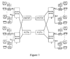
Fig.1 . As shown inFig.1 , a user at End AL1 is to call another user at End BLn to launch a narrowband service, and meanwhile, the computer at End AL1 is to perform network data interworking with the computer at End DL1 to launch a broadband service, the signal outputted by the computer at End AL1 passes a Remote Terminal Unit (RTU), i.e. the so-called modem, and is combined with the telephone signal by a Splitter (SPL) to generate a broadband narrowband hybrid signal. The broadband narrowband hybrid signal is transferred to an access device A, and then the access device A separates the broadband narrowband hybrid signal of End AL1. The broadband signal is transferred to the Internet to be switched and routed, reaches another access device D at End DL1 as the destination, and is transferred to the subscriber line of End DL1 after being combined with the narrowband signal transferred to End DL1 in the access device D, and thus the broadband signal reaches the computer at End DL1. The narrowband signal is transferred to and switched in the PSTN, and is transferred to a third access device B at End BLn as the destination; the narrowband signal is transferred to the subscriber line of End BLn after being combined with the broadband signal transferred to End BLn in the access device B, and reaches the telephone at End BLn after being separated by the SPL. Thus the call to the telephone at End BLn may be put through. - A service board used in an access device and adopted to handle a broadband service and a narrowband service simultaneously is called a broadband-narrowband integrated board, or an integrated board for short.
Fig.2 shows a block diagram illustrating a structure of the integrated board. Each board can support services of multiple subscriber lines in general. However, only the service of one subscriber line in the integrated board is shown inFig.2 . In an uplink direction, the integrated board first handles the hybrid signal containing a broadband signal denoted as CPE1 and a narrowband signal denoted as PHONE1 sent from the user terminal ofsubscriber line 1. The narrowband signal is separated from the hybrid signal by the SPL, and is sent in sequence to a narrowbanduser interface circuit 1, a narrowband data processing unit and the narrowband switching network; the broadband signal is sent to the broadband switching network through abroadband service circuit 1 and a broadband data processing unit. It is to be noted that all the subscriber lines supported by an integrated board share one broadband data processing unit and one narrowband data processing unit. - The operation performed by the integrated board in a downlink direction is opposite to that in the uplink direction. The broadband data processing unit distributes data from the broadband switching network to a requested subscriber line; the narrowband data processing unit distributes data from the narrowband switching network to a requested subscriber line. The broadband signal B1 and the narrowband signal N1 of the first subscriber line are combined by the SPL and transferred to the
subscriber line 1. - As can be seen in
Fig.2 , an integrated board corresponds to a signal transit board. The integrated board separates the broadband signal and the narrowband signal from the subscriber line from each other, and respectively sends the broadband signal and narrowband signal to the respective switching networks; the integrated board also combines and pairs up the broadband signal and the narrowband signal from the respective switching networks as demanded and then sends the combined signal to the subscriber line. - The operation status of an integrated board needs to be tested frequently since the integrated board plays an important role in the circuitry. An ordinary test method includes connecting the signal to be tested to a dedicated test bus, and testing the signal with a dedicated test board or a dedicated test device connected to the test bus. In general, the test for the signal from the subscriber line is called an outgoing test, while the test for the signal from the switching network is called an ingoing test. In the case that the narrowband path is disconnected completely and the test is only performed for the broadband signal, the test is called a net broadband test access. The broadband outgoing test in accordance with the prior art affects the narrowband signal, and as a result, the narrowband signal is interrupted. Meanwhile, the narrowband ingoing test cannot be performed in accordance with the prior art.
- In addition, the X Digital Subscriber Line (XDSL) service is performed in the telephone line. For a narrowband service, each telephone corresponds to one narrowband processing circuit in the narrowband data processing unit, and the number of a telephone is changed if the narrowband processing circuit connected with the telephone is changed. Therefore, the narrowband processing circuit is not required to be changed when a broadband backup is performed. For a broadband service, when the broadband path malfunctions, the connection path is to be switched so as to ensure the continuity of the service. As shown in
Fig.2 , in a normal condition, in the first subscriber line (CPE1+PHONE1), thebroadband service circuit 1 and the narrowbanduser interface circuit 1 respectively provide the broadband service and the narrowband service. When thebroadband service circuit 1 malfunctions and cannot provide the broadband service, for continuing with the broadband service, thebroadband service circuit 1 is to be replaced by another broadband service circuit to provide the broadband service to the first subscriber line. The process is called the broadband backup. The broadband backup in the prior art may result in the interruption of the narrowband signal of the original port. - Document D1 discloses a circuit for testing POTS service on a shared POTS/DSL carrier. The circuit is configured to facilitate testing of the POTS service using an insertion point that is between the DSL filter and the subscriber loop in a manner that is transparent to subscribers.
- Document D2 discloses a relay matrix utilized in a metallic test access systems of DSLAMs, which is used to test the physical disconnection or reconnection of each of the local loops (users).
- Document D3 discloses a DSL splitter providing test access to an interconnected subscriber loop. The DSL splitter in a first test mode provides access to allow testing of an interconnected subscriber loop by way of a DSL input. A disconnection in series with an associated low pass filter (LPF) disconnects POTS input. Such a splitter may similarly provide access to allow testing of the subscriber loop by way of the POTS input in a second test mode. In this second test mode, a by-pass by-passes the LPF, and a disconnection may disconnect an associated high pass filter (HPF) and DSL input.
- The present invention provides a broadband-narrowband integrated board and method for testing the board.
- A broadband-narrowband integrated board according to
claim 1. - A method for testing a broadband-narrowband integrated board according to claim 4:
- Thorough test may be performed for a broadband-narrowband integrated board using the broadband-narrowband integrated board and the method for testing the board provided by the present invention. Meanwhile, other signals are not affected when one line of signal is being tested. Moreover, the narrowband signal will not be affected when the broadband-narrowband integrated board provided by the present invention is used to perform broadband backup. In addition, the narrowband ingoing test can be performed.
-
-
Fig.1 shows a schematic diagram illustrating the structure of an XDSL broadband access system in accordance with the prior art; -
Fig.2 shows a block diagram illustrating the functional structure of a broadband-narrowband integrated board in accordance with the prior art; -
Fig.3 shows a schematic diagram illustrating the service when a broadband-narrowband integrated board in accordance with the present invention is in normal operation; -
Fig.4 shows a schematic diagram illustrating the service when a broadband-narrowband integrated board in accordance with the present invention is under a broadband outgoing test; -
Fig.5 shows a schematic diagram illustrating the service when a broadband-narrowband integrated board in accordance with the present invention is under a broadband ingoing test; -
Fig.6 shows a schematic diagram illustrating the service when a broadband-narrowband integrated board in accordance with the present invention is under a net broadband outgoing test access; -
Fig.7 shows a schematic diagram illustrating the service when a broadband-narrowband integrated board in accordance with the present invention is under a narrowband outgoing test; -
Fig.8 shows a schematic diagram illustrating the service when a broadband-narrowband integrated board in accordance with the present invention is under a narrowband ingoing test; -
Fig.9 shows a schematic diagram illustrating the service when a broadband-narrowband integrated board in accordance with the present invention is used to perform broadband backup; -
Fig.10 shows a schematic diagram illustrating the service when a broadband-narrowband integrated board in accordance with the present invention is under a broadband ingoing test and a broadband outgoing test simultaneously. - The present invention is hereinafter described in detail with reference to embodiments and the drawings so as to make the objective, the technical solutions and the advantages of the present invention clearer.
-
Fig.3 shows a schematic diagram illustrating the service when a broadband-narrowband integrated board in accordance with the present invention is in normal operation. - In
Fig.3 "A" denotes any of the subscriber lines on the integrated board, the CPE / PHONE end is connected to a user equipment, the XDSL end is the broadband interface and is connected to the broadband switching network, the Subscriber Line Interface Circuit (SLIC) terminal is connected to the narrowband switching network. - A broadband outgoing test switch, i.e. the first switching device, which is denoted as KOA in the Ath subscriber line, is provided at the CPE / PHONE end of the subscriber line. A broadband ingoing test switch, i.e. the second switching device, which is denoted as KIA in the Ath subscriber line, is provided at the XDSL end of the subscriber line. The normally open contact of KOA is connected to a broadband outgoing test bus, the normally closed contact of KOA is connected to the normally closed contact of KIA, and the normally open contact of KIA is connected to a broadband ingoing test bus. The two switches are used for transferring a signal in the subscriber line to the broadband ingoing test bus or the broadband outgoing test bus.
- Two switches in series are connected between the SLIC end of the subscriber line and the subscriber line splitter and protection circuit (SPL+PRT); the two switches are respectively called the narrowband ingoing test switch and the narrowband outgoing test switch. The narrowband ingoing test switch corresponds to a fourth switching device, which has a normally open contact connected to a narrowband ingoing test bus and a normally closed contact connected to the network end of the subscriber line splitter and protection circuit, i.e. the PRT portion. The narrowband outgoing test switch corresponds to a seventh switching device, which has a normally open contact connected to a narrowband outgoing test bus and a normally closed contact connected to the SLIC-A end. The narrowband ingoing test switch is connected with the narrowband outgoing test switch. The two switches are used for transferring a narrowband signal to the narrowband outgoing test bus or the narrowband ingoing test bus as needed. The user end of the subscriber line splitter and protection circuit, i.e. the SPL portion, is connected to the subscriber line; the network end of a measuring splitter and protection circuit, i.e. the PRT portion, is connected to the normally closed contact of the narrowband ingoing test switch.
- In addition, three switches, K1, K2 and K3, respectively corresponding to a sixth switching device, eighth switching device and third switching device, are set as auxiliary switches for the outgoing test and the ingoing test. The auxiliary switch, K1, is located in the narrowband outgoing test bus; the normally open contact of K1 is not connected, and the normally closed contact of K1 is connected to the broadband outgoing test bus. The auxiliary switch, K2, is located in the broadband outgoing test bus; the normally closed contact of K2 is not connected, and the normally open contact of K2 is connected to a test device. The auxiliary switch, K3, is located in the broadband ingoing test bus; the normally closed contact of K3 is connected to the broadband outgoing test bus, and the normally open contact of K3 is connected to the test device.
- The measuring splitter and protection circuit is also connected to the narrowband ingoing test bus; the user end of the measuring splitter and protection circuit, i.e. the SPL portion, is connected to the broadband ingoing test bus, and the network end of the measuring splitter and protection circuit, i.e. the PRT portion, is connected to the narrowband ingoing test bus.
- The above switching devices and the measuring splitter and protection circuit compose a switching device matrix. Preferably, the above switches may be implemented as relays. Specially, the narrowband outgoing test switch and the narrowband ingoing test switch may be integrated into one solid relay, which has a much smaller size than a mechanical relay.
- All the switches are in the normally closed positions in normal operation. Therefore the subscriber line is disconnected from all the test buses, and the broadband outgoing test bus, the narrowband outgoing test bus, the narrowband ingoing test bus and the broadband ingoing test bus are connected to each other. For an uplink service, the broadband component of the signal having entered the integrated board from the CPE-A / PHONE-A end is directly transferred to the broadband switching network through the XDSL-A end, while the narrowband component of the signal is transferred to the PSTN after passing in sequence through the subscriber line splitter and protection circuit and the SLIC-A end. For a downlink service, the narrowband signal having entered the integrated board from the PSTN passes the SPL, and is combined with the broadband signal having entered the integrated board from the broadband switching network. The combined signal is transferred to the CPE-A / PHONE-A end of the subscriber line.
-
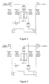
Fig.4 shows a schematic diagram illustrating the service when a broadband-narrowband integrated board in accordance with the present invention is under a broadband outgoing test. - When the broadband outgoing test is to be performed, the broadband outgoing test switch KOA, the auxiliary switch K2, and the narrowband ingoing test switch of the
solid relay S 1 are made to act, that is, these switches are made respectively to turn to the normally open positions. Thus, the broadband outgoing test bus is connected to the CPE-A / PHONE-A end, which enables the outgoing test for the broadband signal in the signal entering the integrated board from the CPE-A / PHONE-A end. The narrowband signal in the signal entering the integrated board from the CPE-A /PHONE-A end passes the broadband outgoing test bus, K2, K3, the measuring splitter and protection circuit, the narrowband ingoing test bus and the solid relay in turn, and eventually is still connected to the SLIC-A end. Thus, the narrowband service is not affected. -
Fig.5 shows a schematic diagram illustrating the service when a broadband-narrowband integrated board in accordance with the present invention is under a broadband ingoing test. - When the broadband ingoing test is to be performed, the broadband ingoing test switch KIA and the auxiliary switch K3 are made to act, that is, the two switches are made respectively turn to the normally open positions. Thus, the broadband ingoing test bus is connected to the XDSL-A end, which enables the ingoing test for the broadband signal entering the integrated board from the XDSL-A end. The narrowband signal of the Ath subscriber line still enters the integrated board from the SLIC-A end, passes the solid relay S1, the subscriber line splitter and protection circuit and broadband outgoing test switch KOA in sequence, and is sent to the user through the CPE-A / PHONE-A end. Thus, the narrowband service is not affected.
-
Fig.6 shows a schematic diagram illustrating the service when a net broadband outgoing test access is performed for a broadband-narrowband integrated board in accordance with the present invention. - When the net broadband outgoing test access is to be performed, the broadband outgoing test switch KOA and the auxiliary switches K1, K2, and K3 are made respectively turn to the normally open positions. Thus, the broadband outgoing test bus is connected to the Ath subscriber line, which enables the outgoing test for the broadband signal in the Ath subscriber line. There is no path for transferring the narrowband signal in the Ath subscriber line to the SLIC-A end, and thus the narrowband service is disconnected completely. Therefore, the net broadband outgoing test access may be performed.
-
Fig.7 shows a schematic diagram illustrating the service when a broadband-narrowband integrated board in accordance with the present invention is under a narrowband outgoing test. - When the narrowband outgoing test is to be performed, the auxiliary switch K2 and the narrowband outgoing test switch of the solid relay S1, are made to act, that is, the switches are made respectively turn to the normally open positions. Thus, the path for broadband services is not changed, that is, the broadband services are not changed. The narrowband signal in the Ath subscriber line is transferred to the narrowband outgoing test bus and then to the broadband outgoing test bus, and thus the narrowband signal at the CPE-A / PHONE-A end may be tested through the broadband outgoing test bus.
-
Fig.8 shows a schematic diagram illustrating the service when a broadband-narrowband integrated board in accordance with the present invention is under a narrowband ingoing test. - When the narrowband ingoing test is to be performed, the auxiliary switch K3 and the narrowband ingoing test switch of the solid relay S1 are made to act, that is, the switches are made respectively turn to the normally open positions. Thus, the path for broadband services is not changed, that is, the broadband services are not changed. The narrowband signal entering the integrated board from the SLIC-A end is transferred via the solid relay to the narrowband ingoing test bus and in turn to the broadband ingoing test bus; thus the narrowband signal at the SLIC-A end may be tested through the broadband ingoing test bus.
-
Fig.9 shows a schematic diagram illustrating the service when a broadband-narrowband integrated board in accordance with the present invention is used to perform broadband backup. - When the XDSL-B port malfunctions and cannot provide a broadband service, for continuing with the broadband service of the Bth subscriber line, the XDSL-B port is to be replaced by another broadband port to provide the broadband service to the Bth subscriber line. It is supposed that the XDSL-A port accomplishes the backup task in
Fig.9 . In this case, the broadband outgoing test switch KOB, the broadband ingoing test switch KIA and the narrowband ingoing test switch of the solid relay S2, are made to act, that is, the switches are made respectively turn to the normally open positions. Thus, the broadband signal from the XDSL-A end is transferred to the CPE-B / PHONE-B end through the broadband ingoing test switch KIA, the broadband ingoing test bus, the auxiliary switches K3 and K2, the broadband outgoing test bus and the broadband outgoing test switch KOB, which keeps the connection of the broadband service of the Bth subscriber line. The narrowband signal at the SLIC-B end is transferred to the CPE-B / PHONE-B end through the solid relay S2, the narrowband ingoing test bus, the measuring splitter and protection circuit, the auxiliary switches K3 and K2, and the broadband outgoing test bus, and thus the narrowband service of the Bth subscriber line is kept. -
Fig.10 shows a schematic diagram illustrating the service when a broadband-narrowband integrated board in accordance with the present invention is under a broadband ingoing test and a broadband outgoing test simultaneously. - For performing simultaneously the broadband outgoing test and the broadband ingoing test without affecting the narrowband service, the connection between the broadband outgoing test bus and the user end of the measuring splitter and protection circuit is to be kept, which may be implemented by directly connecting the broadband outgoing test bus to the user end of the measuring splitter and protection circuit. For implementing the services respectively shown in
Figs.3-9 , the broadband outgoing test bus and the user end of the measuring splitter and protection circuit may be connected with an auxiliary switch K4, i.e. the fifth switching device. The auxiliary switch K4, is located at the user end of the measuring splitter and protection circuit, the normally open contact of the auxiliary switch K4 is connected to the broadband outgoing test bus, and the normally closed contact of the auxiliary switch K4 is not connected. - When the broadband outgoing test and the broadband ingoing test are performed simultaneously, the broadband outgoing test switch KOA, the broadband ingoing test switch KIA and the auxiliary switches K2 and K3, are made to act, that is, the switches are made respectively turn to the normally open positions,. Thus, the broadband signal from the CPE-A / PHONE-A end is transferred to the outgoing test bus while the broadband signal from the XDSL-A end is transferred to the ingoing test bus. Thereby, the broadband outgoing test and the broadband ingoing test may be performed simultaneously. At the same time, the auxiliary switch K4 and the narrowband ingoing test switch of the solid relay S1, are made respectively turn to the normally open positions. Thus, the CPE-A / PHONE-A end is connected to the SLIC-A end through the broadband outgoing test switch KOA, the broadband outgoing test bus, the auxiliary switch K4, the measuring splitter and protection circuit, the narrowband ingoing test bus and the solid relay, and the connection of the narrowband service is kept. When the functions respectively shown in
Figs.3 and9 are to be implemented, the auxiliary switch K4 is made turn to the normally closed position. - It is to be noted that in the above description, it is guaranteed that all the switches are in the normally open positions when the broadband-narrowband integrated board operates normally. If it is not required that all the switches be in the normally open positions when the broadband-narrowband integrated board operates normally, the connection relation between the contacts of the switches may be changed as long as it is ensured that the connection relation between the subscriber line and the test buses is the same as that described above when various functions are to be implemented.
- The present invention also provides a method for testing the broadband-narrowband integrated board corresponding to the above broadband-narrowband integrated board with the test function. The method includes the following processes.
- Step a: setting test buses and a switching device matrix on the broadband-narrowband integrated board;
- Step b: selectively connecting the test buses to the subscriber line using the switching device matrix as demanded, so as to make a service signal to be tested enter the test bus and to form a path for a service not to be tested;
- Step c: testing the signal to be tested through the test bus.
- The test buses include a broadband outgoing test bus, a broadband ingoing test bus, a narrowband outgoing test bus and a narrowband ingoing test bus.
- The process of setting the switching device matrix includes the following.
- A broadband outgoing test switch KOA is set at the CPE / PHONE end of the subscriber line; and a broadband ingoing test switch KIA is set at the XDSL end of the subscriber line. The normally open contact of KOA is connected to the broadband outgoing test bus, the normally closed contact of KOA is connected to the normally closed contact of KIA, and the normally open contact of KIA is connected to the broadband ingoing test bus.
- Two switches in series are set between the SLIC end of the subscriber line and the subscriber line splitter and protection circuit, and are respectively called as a narrowband ingoing test switch and a narrowband outgoing test switch. The normally open contact of the narrowband ingoing test switch is connected to the narrowband ingoing test bus while the normally closed contact of the narrowband ingoing test switch is connected to the network end of the subscriber line splitter and protection circuit, i.e. the PRT portion. The normally open contact of the narrowband outgoing test switch is connected to the narrowband outgoing test bus while the normally closed contact of the narrowband outgoing test switch is connected to the SLIC-A end. The narrowband ingoing test switch is connected to the narrowband outgoing test switch. Preferably, the narrowband outgoing test switch and the narrowband ingoing test switch may be integrated into one solid relay.
- An auxiliary switch K1 is set in the narrowband outgoing test bus. The normally open contact of K1 is not connected, and the normally closed contact of K1 is connected to the broadband outgoing test bus. An auxiliary switch K2 is set in the broadband outgoing test bus, the normally closed contact of K2 is not connected, and the normally open contact of K2 is connected to a test device. An auxiliary switch K3 is set in the broadband ingoing test bus, the normally closed contact of K3 is connected to the broadband outgoing test bus, and the normally open contact of K3 is connected to the test device.
- A measuring splitter and protection circuit is set in the narrowband ingoing test bus, the user end of the SPL+PRT, i.e. the SPL portion, is connected to the broadband ingoing test bus, and the network end of the SPL+PRT, i.e. the PRT portion, is connected to the narrowband ingoing test bus.
- If the service signal to be tested is a broadband uplink signal, that is, the broadband outgoing test is to be performed for the integrated board, the broadband outgoing test switch KOA, the auxiliary switch K2 and the narrowband ingoing test switch of the solid relay S1, are made to act, that is, the switches are made turn to the normally open positions. Thereby, the broadband uplink signal enters the test device through the broadband outgoing test bus. Meanwhile, the broadband outgoing test bus and the narrowband ingoing test bus are connected through the measuring splitter and protection circuit; the network end of the measuring splitter and protection circuit is connected to the narrowband ingoing test bus and user end of the measuring splitter and protection circuit is connected to the broadband outgoing test bus. Moreover, the narrowband ingoing test bus is connected to the SLIC. Thus, the path for narrowband services is formed.
- If the service signal to be tested is a broadband downlink signal, that is, the broadband ingoing test is to be performed for the integrated board, the broadband ingoing test switch KIA and the auxiliary switch K3 are made to act, that is, the switches are made turn to the normally open positions. Thereby, the broadband downlink signal enters the test device through the broadband ingoing test bus. Meanwhile, the path for narrowband services in normal operation is used continuously to perform the narrowband service.
- When the net broadband outgoing test access is to be performed for the integrated board, the broadband outgoing test switch KOA and the auxiliary switches K1, K2, and K3 are made turn to the normally open positions. Thereby, the broadband uplink signal enters the test device through the broadband outgoing test bus. Meanwhile, the narrowband service is disconnected as required in net broadband outgoing test access.
- If the service signal to be tested is a narrowband uplink signal, that is, the narrowband outgoing test is to be performed for the integrated board, the auxiliary switch K2 and the narrowband outgoing test switch of the solid relay S1 are made to act, that is, the switches are made turn to the normally open positions. Thus, the narrowband outgoing test bus is connected to the broadband outgoing test bus; the narrowband uplink signal enters the test device through the narrowband outgoing test bus and the broadband outgoing test bus. Meanwhile, the path for broadband services in normal operation is used continuously to perform the broadband service.
- If the service signal to be tested is a narrowband downlink signal, that is, the narrowband ingoing test is to be performed for the integrated board, the auxiliary switch K3 and the narrowband ingoing test switch of the
solid relay S 1 are made to act, that is, the switches are made turn to the normally open positions. Thus, the narrowband ingoing test bus and the broadband ingoing test bus are connected to each other by the measuring splitter and protection circuit; the user end of the measuring splitter and protection circuit is connected to the broadband ingoing test bus, and network end of the measuring splitter and protection circuit is connected to the narrowband ingoing test bus. Moreover, the SLIC is connected to the narrowband ingoing test bus and thus the narrowband downlink signal enters the test device through the narrowband ingoing test bus, the measuring splitter and protection circuit and the broadband ingoing test bus. Meanwhile, the path for broadband services in normal operation is used continuously to perform the broadband service. - If the service signal to be tested contains the broadband downlink signal and the broadband uplink signal, the broadband uplink signal and broadband downlink signal are to enter the test device respectively through the broadband outgoing test bus and the broadband ingoing test bus. Meanwhile, the broadband ingoing test bus and the narrowband ingoing test bus are connected through the measuring splitter and protection circuit: the user end of the measuring splitter and protection circuit is connected to the broadband ingoing test bus and the network end of the measuring splitter and protection circuit is connected to the narrowband ingoing test bus. The user end of the measuring splitter and protection circuit is also connected to the broadband outgoing test bus. The SLIC is connected to the narrowband ingoing test bus. Thus, the path for narrowband services is formed.
- The user end of the measuring splitter and protection circuit may be connected to the broadband outgoing test bus directly or via an auxiliary switch K4. The auxiliary switch K4 is set at the user end of the measuring splitter and protection circuit and has a normally open contact connected to the broadband outgoing test bus and a normally closed contact not connected.
- Thus, if the service signal to be tested contains the broadband downlink signal and the broadband uplink signal, for implementing the above connection relation, the broadband outgoing test switch KOA, the broadband ingoing test switch KIA, the narrowband ingoing test switch of the solid relay S1 and the auxiliary switches K2, K3 and K4 are made to act, that is, the switches are made turn to the normally open positions. Moreover, the auxiliary switch K4 is kept in the normally closed position when a normal service is being performed or a signal to be tested does not contain both the broadband downlink signal and the broadband uplink signal at the same time.
- If the broadband interface of the original subscriber line malfunctions after the process a, the broadband interface of a backup subscriber line is used to keep on providing the broadband service to the original subscriber line. It is assumed that the broadband outgoing test switch of the original subscriber line is KOB, and the solid relay between the SLIC end of the original subscriber line and the subscriber line splitter and protection circuit of the original subscriber line is S2.
- KOB, KIA and the narrowband ingoing test switch of the solid relay S2 are made turn to the normally open positions so that, the broadband interface of the backup subscriber line is connected to the broadband ingoing test bus, the CPE/PHONE end of the original subscriber line is connected to the broadband outgoing test bus, and the broadband ingoing test bus is connected to the broadband outgoing test bus, and thus a new broadband service path is formed; meanwhile, the narrowband ingoing test bus is connected to the broadband ingoing test bus by the measuring splitter and protection circuit, where the user end of the measuring splitter and protection circuit is connected to the broadband ingoing test bus and the network end of the measuring splitter and protection circuit is connected to the narrowband ingoing test bus, and the SLIC of the original subscriber line is connected to the narrowband ingoing test bus, and thus a new narrowband service path is formed.
- The foregoing is only preferred embodiments of the present invention and is not for use in limiting the protection scope thereof. Any modification, equivalent substitution, and improvement without departing from the principle of the present invention should be covered in the protection scope of the present invention.
Claims (12)
- A broadband-narrowband integrated board, comprising:a test bus for connecting a service signal to a test device; anda switching device matrix for connecting the test bus to a subscriber line so as to make a service signal, which is either a broadband signal or a narrowband signal, to be tested enter the test buscharacterized in that
the test bus comprises:a broadband outgoing test bus, a broadband ingoing test bus, a narrowband outgoing test bus and a narrowband ingoing test bus andthat the switching device matrix comprises:a first switching device (KOA) connected to a user terminal, wherein a normally open contact thereof is connected to the broadband outgoing test bus, and a normally closed contact thereof is connected to a normally closed contact of a second switching device (KIA);the second switching device (KIA) connected to a broadband interface, wherein a normally open contact thereof is connected to the broadband ingoing test bus;a third switching device (K3) connected to the broadband ingoing test bus, wherein a normally open contact thereof is connected to the test device and a normally closed contact thereof is connected to the broadband outgoing test bus;a fourth switching device connected to a seventh switching device, wherein a normally open contact thereof is connected to the narrowband ingoing test bus and a normally closed contact thereof is connected to a subscriber line splitter and protection circuit;sixth switching device (K1) connected to the narrowband test bus, wherein a normally open contact thereof is not connected and a normally closed contact thereof is connected to the broadband outgoing test bus;the seventh switching device, wherein a normally open contact thereof is connected to the narrowband outgoing test bus and a normally closed contact thereof is connected to a Subscriber Line Interface Circuit;an eighth switching device (K2) connected to the broadband outgoing test bus, wherein a normally open contact thereof is connected to the test device and a normally closed contact thereof is not connected;a measuring splitter and protection circuit, wherein a user end thereof is connected to the broadband ingoing test bus and a network end thereof is connected to the narrowband ingoing test bus. - The broadband-narrowband integrated board of Claim 1, further comprising:a fifth switching device connected to the user end of the measuring splitter and protection circuit, wherein a normally open contact thereof is connected to the broadband outgoing test bus and a normally closed contact thereof is not connected.
- The broadband-narrowband integrated board of Claim 1 or 2, wherein the fourth switching device and the seventh switching device are integrated as a solid relay.
- A method for testing a broadband-narrowband integrated board, comprising:setting a test bus and a switching device matrix on the broadband-narrowband integrated board;selectively connecting the test bus to a subscriber line using the switching device matrix, so as to make a service signal, which is either a broadband signal or a narrowband signal, to be tested enter the test bus; andtesting the signal to be tested through the test buscharacterized in that
the process of setting the test bus on the broadband-narrowband integrated board comprises:setting a broadband outgoing test bus, a broadband ingoing test bus, a narrowband outgoing test bus and a narrowband ingoing test bus on the broadband-narrowband integrated board andthat the process of setting the switching device matrix on the broadband-narrowband integrated board comprises:setting a first switching device connected to a user terminal, and respectively connecting a normally open contact and a normally closed contact of the first switching device to the broadband outgoing test bus and a normally closed contact of a second switching device;setting the second switching device connected to the broadband interface, and connecting a normally open contact of the second switching device to the narrowband ingoing test bus;setting a third switching device connected to the broadband ingoing test bus, and respectively connecting a normally open contact and a normally closed contact of the third switching device to the test bus and the broadband outgoing test bus;setting a fourth switching device connected to a seventh switching device, and respectively connecting a normally open contact and a normally closed contact of the fourth switching device to the narrowband ingoing test bus and a subscriber line splitter and protection circuit;setting a sixth switching device connected to the narrowband outgoing test bus, leaving a normally open contact of the sixth switching device unconnected and connecting a normally closed contact of the sixth switching device to the broadband outgoing test bus;setting the seventh switching device connected to the fourth switching device, and respectively connecting a normally open contact and a normally closed contact of the seventh switching device to the narrowband ingoing test bus and a subscriber line interface circuit;setting an eighth switching device connected to the broadband outgoing test bus, connecting a normally open contact of the eighth switching device to the test device and leaving a normally closed contact of the eighth switching device unconnected;setting a measuring splitter and protection circuit, and respectively connecting a user end and a network end of the measuring splitter and protection circuit to the broadband ingoing test bus and the narrowband ingoing test bus. - The method of Claim 4, wherein in the case that the service signal to be tested is a broadband uplink signal, connecting the test bus to the subscriber line so as to make the service signal to be tested enter the test bus comprises:making the first switching device, the eighth switching device and the fourth switching device turn to normally open positions and thus making:the broadband uplink signal enter the test device through the broadband outgoing test bus;the network end and the user end of the measuring splitter and protection circuit be respectively connected to the narrowband ingoing test bus and the broadband outgoing test bus;the narrowband ingoing test bus be connected to the subscriber line interface circuit.
- The method of Claim 4, wherein in the case that the service signal to be tested is a broadband downlink signal, connecting the test bus to the subscriber line so as to make the service signal to be tested enter the test bus comprises:making the second switching device and the third switching device turn to normally open positions and thus making:the broadband downlink signal enter the test device through the broadband ingoing test bus;the narrowband service be performed continuously through a narrowband service path in normal operation.
- The method of Claim 4, wherein in the case that the service signal to be tested is a broadband uplink signal after the narrowband service is interrupted, connecting the test bus to the subscriber line so as to make the service signal to be tested enter the test bus comprises:making the first switching device, the third switching device, the sixth switching device and the eighth switching device turn to normally open positions and thus making:the broadband uplink signal enter the test device through the broadband outgoing test bus.
- The method of Claim 4, wherein in the case that the service signal to be tested is a narrowband uplink signal, connecting the test bus to the subscriber line so as to make the service signal to be tested enter the test bus comprises:making the eighth switching device and the seventh switching device turn to normally open positions and thus making:the narrowband outgoing test bus be connected to the broadband outgoing test bus;the narrowband uplink signal enter the test device through the narrowband outgoing test bus and the broadband outgoing test bus;the broadband service be performed continuously through a broadband service path in normal operation.
- The method of Claim 4, wherein in the case that the service signal to be tested is a narrowband downlink signal, connecting the test bus to the subscriber line so as to make the service signal to be tested enter the test bus comprises:making the third switching device and the fourth switching device turn to normally open positions and thus making:the user end and network end of the measuring splitter and protection circuit be respectively connected to the broadband ingoing test bus and the narrowband ingoing test bus;the subscriber line interface circuit be connected to the narrowband ingoing test bus so that the narrowband downlink signal enters the test device through the narrowband ingoing test bus, the measuring splitter and protection circuit and the broadband ingoing test bus.the broadband service be performed continuously through a broadband service path of normal operation.
- The method of Claim 4, wherein setting the switching device matrix on the broadband-narrowband integrated board further comprises:setting a fifth switching device connected to the user end of the measuring splitter and protection circuit, connecting a normally open contact of the fifth switching device to the broadband outgoing test bus and leaving a normally closed contact of the fifth switching device unconnected; andwherein in the case that the service signal to be tested contains a broadband downlink signal and a broadband uplink signal, connecting the test bus to the subscriber line so as to make the service signal to be tested enter the test bus comprises:making the first switching device, the second switching device, the third switching device, the fifth switching device and the eighth switching device turn to normally open positions and thus making:the broadband uplink signal and the broadband downlink signal enter the test device respectively through the broadband outgoing test bus and the broadband ingoing test bus;the user end and network end of the measuring splitter and protection circuit be respectively connected to the broadband outgoing test bus and the narrowband ingoing test bus;the subscriber line interface circuit be connected to the narrowband ingoing test bus so as to form a narrowband service path.
- The method of Claim 4, further comprising:when the broadband interface of an original subscriber line malfunctions, using the broadband interface of a backup subscriber line to provide the broadband service to the original subscriber line.
- The method of Claim 11, wherein using the broadband interface of the backup subscriber line to provide the broadband service to the original subscriber line comprises:making the first switching device of the original subscriber line, the second switching device of the backup subscriber line and the fourth switching device of the original subscriber line turn to normally open positions and thus making:the broadband interface of the backup subscriber line be connected to the broadband ingoing test bus, the user terminal of the original subscriber line be connected to the broadband outgoing test bus, the broadband ingoing test bus be connected to the broadband outgoing test bus, so as to form a new broadband service path;the user end and network end of the measuring splitter and protection circuit be respectively connected to the broadband ingoing test bus and the narrowband ingoing test bus, the subscriber line interface circuit of the original subscriber line be connected to the narrowband ingoing test bus, so as to form a new narrowband service path.
Applications Claiming Priority (2)
| Application Number | Priority Date | Filing Date | Title |
|---|---|---|---|
| CNB2005101210648A CN100531256C (en) | 2005-12-20 | 2005-12-20 | Broad-narrow band-in-one-board with detecting function and detecting method |
| PCT/CN2006/002760 WO2007071146A1 (en) | 2005-12-20 | 2006-10-18 | A broad-narrow band integrated board and method for testing said board |
Publications (3)
| Publication Number | Publication Date |
|---|---|
| EP1906546A1 EP1906546A1 (en) | 2008-04-02 |
| EP1906546A4 EP1906546A4 (en) | 2009-01-14 |
| EP1906546B1 true EP1906546B1 (en) | 2012-12-12 |
Family
ID=37298329
Family Applications (1)
| Application Number | Title | Priority Date | Filing Date |
|---|---|---|---|
| EP06804978A Not-in-force EP1906546B1 (en) | 2005-12-20 | 2006-10-18 | A broad-narrow band integrated board and method for testing said board |
Country Status (4)
| Country | Link |
|---|---|
| EP (1) | EP1906546B1 (en) |
| CN (2) | CN100531256C (en) |
| ES (1) | ES2397930T3 (en) |
| WO (1) | WO2007071146A1 (en) |
Families Citing this family (2)
| Publication number | Priority date | Publication date | Assignee | Title |
|---|---|---|---|---|
| CN101079920B (en) * | 2007-06-28 | 2011-11-23 | 中兴通讯股份有限公司 | Narrow user board with testing function and automatic testing method of user line |
| TWI520561B (en) * | 2012-11-09 | 2016-02-01 | 緯創資通股份有限公司 | Test board |
Family Cites Families (7)
| Publication number | Priority date | Publication date | Assignee | Title |
|---|---|---|---|---|
| CN1108043C (en) * | 1999-12-31 | 2003-05-07 | 西安交通大学 | Narrow-band and broad-band overall led-in equipment |
| US6785325B1 (en) * | 2000-06-07 | 2004-08-31 | Nortel Networks Limited | DSL splitter providing test access to an interconnected subscriber loop and method |
| US7068758B1 (en) * | 2000-10-23 | 2006-06-27 | Alcatel Canada Inc. | Integrated metallic access for high port density DSLAM |
| US6618469B2 (en) * | 2002-02-05 | 2003-09-09 | Adc Dsl Systems, Inc. | Circuits and methods for testing POTS service |
| CN1194557C (en) * | 2003-08-29 | 2005-03-23 | 华为技术有限公司 | Total distributed frame method for x DSL and narrow band exchange access and its device |
| CN100341286C (en) * | 2004-02-21 | 2007-10-03 | 华为技术有限公司 | Method and device for implementing central office artificial testing in service single board |
| CN1674458B (en) * | 2004-03-23 | 2010-11-03 | 华为技术有限公司 | Testing method for digital user line and local side wideband equipment |
-
2005
- 2005-12-20 CN CNB2005101210648A patent/CN100531256C/en not_active Expired - Fee Related
-
2006
- 2006-10-18 EP EP06804978A patent/EP1906546B1/en not_active Not-in-force
- 2006-10-18 ES ES06804978T patent/ES2397930T3/en active Active
- 2006-10-18 CN CNA200680011682XA patent/CN101156326A/en active Pending
- 2006-10-18 WO PCT/CN2006/002760 patent/WO2007071146A1/en active Application Filing
Also Published As
| Publication number | Publication date |
|---|---|
| WO2007071146A1 (en) | 2007-06-28 |
| ES2397930T3 (en) | 2013-03-12 |
| EP1906546A1 (en) | 2008-04-02 |
| CN101156326A (en) | 2008-04-02 |
| CN100531256C (en) | 2009-08-19 |
| CN1859468A (en) | 2006-11-08 |
| EP1906546A4 (en) | 2009-01-14 |
Similar Documents
| Publication | Publication Date | Title |
|---|---|---|
| JP3905733B2 (en) | Subscriber line test system and method | |
| US6574313B1 (en) | Voice over DSL method and system for supporting a lifeline | |
| US6470074B2 (en) | System and method for providing data and voice services on a shared line | |
| US6546089B1 (en) | Method and system for supporting a lifeline associated with voice over DSL | |
| US6594343B1 (en) | Splitter bypass architecture for testing multiple ports | |
| EP1088437A2 (en) | Upgrading of subscriber connection | |
| US20070280288A1 (en) | Apparatus And Method For Realizing User Switching Between Ip Network And Pstn Network | |
| TW518898B (en) | Systems and methods for electronically managing digital subscriber line (DSL) telecommunications connections | |
| US7688744B2 (en) | Broadband test line access circuit, broadband test-line access board and broadband test device | |
| JP2002232562A (en) | Line card for system communication and method for supporting pots, asymmetrical ds line service and symmetrical ds line service | |
| CN100353680C (en) | Device of implementing backup for communication equipment in multistage and method of rearranging main and standby devices | |
| EP1906546B1 (en) | A broad-narrow band integrated board and method for testing said board | |
| ES2394357T3 (en) | System and method to improve communications security | |
| CN105721181B (en) | Method, backbone switch and the access switch of message transmissions | |
| US8983052B2 (en) | Method and apparatus for communication having critically assured services | |
| WO2011137705A1 (en) | Method for implementing main distribution frame and main distribution frame | |
| US7039732B1 (en) | Method and apparatus for providing redundancy between card elements in a chassis | |
| EP1903832B1 (en) | A method and system for signal splitting and a splitter board | |
| WO2008025296A1 (en) | Integrated access single board for accessing multiple businesses | |
| WO2009036668A1 (en) | Communication network, distribution frame, communication method and method for installing distribution frame | |
| US6519325B1 (en) | Control panel with DSL bypass circuit | |
| JPH04122162A (en) | Self-diagnosis system for terminal system equipment | |
| TW519813B (en) | Public branch exchange system with multiple emergency lines | |
| US20080075093A1 (en) | Subscriber card | |
| US20060262923A1 (en) | Communication networks that include a high pass filter circuit for connecting communications wiring at a customer premises location to an outside plant loop and methods of operating the same |
Legal Events
| Date | Code | Title | Description |
|---|---|---|---|
| PUAI | Public reference made under article 153(3) epc to a published international application that has entered the european phase |
Free format text: ORIGINAL CODE: 0009012 |
|
| 17P | Request for examination filed |
Effective date: 20080218 |
|
| AK | Designated contracting states |
Kind code of ref document: A1 Designated state(s): AT BE BG CH CY CZ DE DK EE ES FI FR GB GR HU IE IS IT LI LT LU LV MC NL PL PT RO SE SI SK TR |
|
| DAX | Request for extension of the european patent (deleted) | ||
| A4 | Supplementary search report drawn up and despatched |
Effective date: 20081215 |
|
| 17Q | First examination report despatched |
Effective date: 20090402 |
|
| REG | Reference to a national code |
Ref country code: DE Ref legal event code: R079 Ref document number: 602006033616 Country of ref document: DE Free format text: PREVIOUS MAIN CLASS: H04B0003460000 Ipc: H04M0003220000 |
|
| GRAP | Despatch of communication of intention to grant a patent |
Free format text: ORIGINAL CODE: EPIDOSNIGR1 |
|
| RIC1 | Information provided on ipc code assigned before grant |
Ipc: H04M 3/30 20060101ALI20120605BHEP Ipc: H04M 3/00 20060101ALI20120605BHEP Ipc: H04M 7/00 20060101ALI20120605BHEP Ipc: H04M 3/22 20060101AFI20120605BHEP |
|
| DAX | Request for extension of the european patent (deleted) | ||
| GRAS | Grant fee paid |
Free format text: ORIGINAL CODE: EPIDOSNIGR3 |
|
| GRAA | (expected) grant |
Free format text: ORIGINAL CODE: 0009210 |
|
| AK | Designated contracting states |
Kind code of ref document: B1 Designated state(s): AT BE BG CH CY CZ DE DK EE ES FI FR GB GR HU IE IS IT LI LT LU LV MC NL PL PT RO SE SI SK TR |
|
| REG | Reference to a national code |
Ref country code: GB Ref legal event code: FG4D |
|
| REG | Reference to a national code |
Ref country code: CH Ref legal event code: EP |
|
| REG | Reference to a national code |
Ref country code: AT Ref legal event code: REF Ref document number: 588817 Country of ref document: AT Kind code of ref document: T Effective date: 20121215 |
|
| REG | Reference to a national code |
Ref country code: IE Ref legal event code: FG4D |
|
| REG | Reference to a national code |
Ref country code: DE Ref legal event code: R096 Ref document number: 602006033616 Country of ref document: DE Effective date: 20130131 |
|
| REG | Reference to a national code |
Ref country code: NL Ref legal event code: T3 |
|
| REG | Reference to a national code |
Ref country code: ES Ref legal event code: FG2A Ref document number: 2397930 Country of ref document: ES Kind code of ref document: T3 Effective date: 20130312 |
|
| PG25 | Lapsed in a contracting state [announced via postgrant information from national office to epo] |
Ref country code: SE Free format text: LAPSE BECAUSE OF FAILURE TO SUBMIT A TRANSLATION OF THE DESCRIPTION OR TO PAY THE FEE WITHIN THE PRESCRIBED TIME-LIMIT Effective date: 20121212 Ref country code: LT Free format text: LAPSE BECAUSE OF FAILURE TO SUBMIT A TRANSLATION OF THE DESCRIPTION OR TO PAY THE FEE WITHIN THE PRESCRIBED TIME-LIMIT Effective date: 20121212 Ref country code: FI Free format text: LAPSE BECAUSE OF FAILURE TO SUBMIT A TRANSLATION OF THE DESCRIPTION OR TO PAY THE FEE WITHIN THE PRESCRIBED TIME-LIMIT Effective date: 20121212 |
|
| REG | Reference to a national code |
Ref country code: AT Ref legal event code: MK05 Ref document number: 588817 Country of ref document: AT Kind code of ref document: T Effective date: 20121212 |
|
| REG | Reference to a national code |
Ref country code: LT Ref legal event code: MG4D |
|
| PG25 | Lapsed in a contracting state [announced via postgrant information from national office to epo] |
Ref country code: SI Free format text: LAPSE BECAUSE OF FAILURE TO SUBMIT A TRANSLATION OF THE DESCRIPTION OR TO PAY THE FEE WITHIN THE PRESCRIBED TIME-LIMIT Effective date: 20121212 Ref country code: GR Free format text: LAPSE BECAUSE OF FAILURE TO SUBMIT A TRANSLATION OF THE DESCRIPTION OR TO PAY THE FEE WITHIN THE PRESCRIBED TIME-LIMIT Effective date: 20130313 Ref country code: LV Free format text: LAPSE BECAUSE OF FAILURE TO SUBMIT A TRANSLATION OF THE DESCRIPTION OR TO PAY THE FEE WITHIN THE PRESCRIBED TIME-LIMIT Effective date: 20121212 |
|
| PG25 | Lapsed in a contracting state [announced via postgrant information from national office to epo] |
Ref country code: EE Free format text: LAPSE BECAUSE OF FAILURE TO SUBMIT A TRANSLATION OF THE DESCRIPTION OR TO PAY THE FEE WITHIN THE PRESCRIBED TIME-LIMIT Effective date: 20121212 Ref country code: CZ Free format text: LAPSE BECAUSE OF FAILURE TO SUBMIT A TRANSLATION OF THE DESCRIPTION OR TO PAY THE FEE WITHIN THE PRESCRIBED TIME-LIMIT Effective date: 20121212 Ref country code: BG Free format text: LAPSE BECAUSE OF FAILURE TO SUBMIT A TRANSLATION OF THE DESCRIPTION OR TO PAY THE FEE WITHIN THE PRESCRIBED TIME-LIMIT Effective date: 20130312 Ref country code: IS Free format text: LAPSE BECAUSE OF FAILURE TO SUBMIT A TRANSLATION OF THE DESCRIPTION OR TO PAY THE FEE WITHIN THE PRESCRIBED TIME-LIMIT Effective date: 20130412 Ref country code: AT Free format text: LAPSE BECAUSE OF FAILURE TO SUBMIT A TRANSLATION OF THE DESCRIPTION OR TO PAY THE FEE WITHIN THE PRESCRIBED TIME-LIMIT Effective date: 20121212 Ref country code: SK Free format text: LAPSE BECAUSE OF FAILURE TO SUBMIT A TRANSLATION OF THE DESCRIPTION OR TO PAY THE FEE WITHIN THE PRESCRIBED TIME-LIMIT Effective date: 20121212 |
|
| PG25 | Lapsed in a contracting state [announced via postgrant information from national office to epo] |
Ref country code: RO Free format text: LAPSE BECAUSE OF FAILURE TO SUBMIT A TRANSLATION OF THE DESCRIPTION OR TO PAY THE FEE WITHIN THE PRESCRIBED TIME-LIMIT Effective date: 20121212 Ref country code: PT Free format text: LAPSE BECAUSE OF FAILURE TO SUBMIT A TRANSLATION OF THE DESCRIPTION OR TO PAY THE FEE WITHIN THE PRESCRIBED TIME-LIMIT Effective date: 20130412 Ref country code: PL Free format text: LAPSE BECAUSE OF FAILURE TO SUBMIT A TRANSLATION OF THE DESCRIPTION OR TO PAY THE FEE WITHIN THE PRESCRIBED TIME-LIMIT Effective date: 20121212 |
|
| PLBE | No opposition filed within time limit |
Free format text: ORIGINAL CODE: 0009261 |
|
| STAA | Information on the status of an ep patent application or granted ep patent |
Free format text: STATUS: NO OPPOSITION FILED WITHIN TIME LIMIT |
|
| PG25 | Lapsed in a contracting state [announced via postgrant information from national office to epo] |
Ref country code: DK Free format text: LAPSE BECAUSE OF FAILURE TO SUBMIT A TRANSLATION OF THE DESCRIPTION OR TO PAY THE FEE WITHIN THE PRESCRIBED TIME-LIMIT Effective date: 20121212 |
|
| 26N | No opposition filed |
Effective date: 20130913 |
|
| PG25 | Lapsed in a contracting state [announced via postgrant information from national office to epo] |
Ref country code: CY Free format text: LAPSE BECAUSE OF FAILURE TO SUBMIT A TRANSLATION OF THE DESCRIPTION OR TO PAY THE FEE WITHIN THE PRESCRIBED TIME-LIMIT Effective date: 20121212 |
|
| REG | Reference to a national code |
Ref country code: DE Ref legal event code: R097 Ref document number: 602006033616 Country of ref document: DE Effective date: 20130913 |
|
| PG25 | Lapsed in a contracting state [announced via postgrant information from national office to epo] |
Ref country code: MC Free format text: LAPSE BECAUSE OF FAILURE TO SUBMIT A TRANSLATION OF THE DESCRIPTION OR TO PAY THE FEE WITHIN THE PRESCRIBED TIME-LIMIT Effective date: 20121212 |
|
| REG | Reference to a national code |
Ref country code: CH Ref legal event code: PL |
|
| REG | Reference to a national code |
Ref country code: IE Ref legal event code: MM4A |
|
| PG25 | Lapsed in a contracting state [announced via postgrant information from national office to epo] |
Ref country code: CH Free format text: LAPSE BECAUSE OF NON-PAYMENT OF DUE FEES Effective date: 20131031 Ref country code: LI Free format text: LAPSE BECAUSE OF NON-PAYMENT OF DUE FEES Effective date: 20131031 |
|
| PG25 | Lapsed in a contracting state [announced via postgrant information from national office to epo] |
Ref country code: IE Free format text: LAPSE BECAUSE OF NON-PAYMENT OF DUE FEES Effective date: 20131018 |
|
| PG25 | Lapsed in a contracting state [announced via postgrant information from national office to epo] |
Ref country code: TR Free format text: LAPSE BECAUSE OF FAILURE TO SUBMIT A TRANSLATION OF THE DESCRIPTION OR TO PAY THE FEE WITHIN THE PRESCRIBED TIME-LIMIT Effective date: 20121212 |
|
| PG25 | Lapsed in a contracting state [announced via postgrant information from national office to epo] |
Ref country code: LU Free format text: LAPSE BECAUSE OF NON-PAYMENT OF DUE FEES Effective date: 20131018 Ref country code: HU Free format text: LAPSE BECAUSE OF FAILURE TO SUBMIT A TRANSLATION OF THE DESCRIPTION OR TO PAY THE FEE WITHIN THE PRESCRIBED TIME-LIMIT; INVALID AB INITIO Effective date: 20061018 |
|
| REG | Reference to a national code |
Ref country code: FR Ref legal event code: PLFP Year of fee payment: 11 |
|
| REG | Reference to a national code |
Ref country code: FR Ref legal event code: PLFP Year of fee payment: 12 |
|
| REG | Reference to a national code |
Ref country code: FR Ref legal event code: PLFP Year of fee payment: 13 |
|
| PGFP | Annual fee paid to national office [announced via postgrant information from national office to epo] |
Ref country code: FR Payment date: 20200914 Year of fee payment: 15 |
|
| PGFP | Annual fee paid to national office [announced via postgrant information from national office to epo] |
Ref country code: BE Payment date: 20200916 Year of fee payment: 15 |
|
| PGFP | Annual fee paid to national office [announced via postgrant information from national office to epo] |
Ref country code: NL Payment date: 20201015 Year of fee payment: 15 |
|
| PGFP | Annual fee paid to national office [announced via postgrant information from national office to epo] |
Ref country code: DE Payment date: 20201006 Year of fee payment: 15 Ref country code: ES Payment date: 20201105 Year of fee payment: 15 Ref country code: GB Payment date: 20201007 Year of fee payment: 15 Ref country code: IT Payment date: 20200911 Year of fee payment: 15 |
|
| REG | Reference to a national code |
Ref country code: DE Ref legal event code: R119 Ref document number: 602006033616 Country of ref document: DE |
|
| REG | Reference to a national code |
Ref country code: NL Ref legal event code: MM Effective date: 20211101 |
|
| REG | Reference to a national code |
Ref country code: BE Ref legal event code: MM Effective date: 20211031 |
|
| GBPC | Gb: european patent ceased through non-payment of renewal fee |
Effective date: 20211018 |
|
| PG25 | Lapsed in a contracting state [announced via postgrant information from national office to epo] |
Ref country code: NL Free format text: LAPSE BECAUSE OF NON-PAYMENT OF DUE FEES Effective date: 20211101 Ref country code: GB Free format text: LAPSE BECAUSE OF NON-PAYMENT OF DUE FEES Effective date: 20211018 Ref country code: DE Free format text: LAPSE BECAUSE OF NON-PAYMENT OF DUE FEES Effective date: 20220503 Ref country code: BE Free format text: LAPSE BECAUSE OF NON-PAYMENT OF DUE FEES Effective date: 20211031 |
|
| PG25 | Lapsed in a contracting state [announced via postgrant information from national office to epo] |
Ref country code: FR Free format text: LAPSE BECAUSE OF NON-PAYMENT OF DUE FEES Effective date: 20211031 |
|
| PG25 | Lapsed in a contracting state [announced via postgrant information from national office to epo] |
Ref country code: IT Free format text: LAPSE BECAUSE OF NON-PAYMENT OF DUE FEES Effective date: 20211018 |
|
| REG | Reference to a national code |
Ref country code: ES Ref legal event code: FD2A Effective date: 20221129 |
|
| PG25 | Lapsed in a contracting state [announced via postgrant information from national office to epo] |
Ref country code: ES Free format text: LAPSE BECAUSE OF NON-PAYMENT OF DUE FEES Effective date: 20211019 |