EP1906546B1 - Ein breit-schmalband integrierter schaltkreis und prüfungsverfahren eines solchen schaltkreises - Google Patents
Ein breit-schmalband integrierter schaltkreis und prüfungsverfahren eines solchen schaltkreises Download PDFInfo
- Publication number
- EP1906546B1 EP1906546B1 EP06804978A EP06804978A EP1906546B1 EP 1906546 B1 EP1906546 B1 EP 1906546B1 EP 06804978 A EP06804978 A EP 06804978A EP 06804978 A EP06804978 A EP 06804978A EP 1906546 B1 EP1906546 B1 EP 1906546B1
- Authority
- EP
- European Patent Office
- Prior art keywords
- broadband
- test bus
- narrowband
- switching device
- ingoing
- Prior art date
- Legal status (The legal status is an assumption and is not a legal conclusion. Google has not performed a legal analysis and makes no representation as to the accuracy of the status listed.)
- Not-in-force
Links
- 238000012360 testing method Methods 0.000 title claims description 328
- 238000000034 method Methods 0.000 title claims description 23
- 239000007787 solid Substances 0.000 claims description 19
- 239000011159 matrix material Substances 0.000 claims description 11
- 230000008569 process Effects 0.000 claims description 7
- 230000007257 malfunction Effects 0.000 claims description 5
- 238000010586 diagram Methods 0.000 description 19
- 238000012545 processing Methods 0.000 description 10
- 238000005516 engineering process Methods 0.000 description 3
- 101100042631 Saccharomyces cerevisiae (strain ATCC 204508 / S288c) SIN3 gene Proteins 0.000 description 2
- 230000006872 improvement Effects 0.000 description 1
- 238000003780 insertion Methods 0.000 description 1
- 230000037431 insertion Effects 0.000 description 1
- 230000004048 modification Effects 0.000 description 1
- 238000012986 modification Methods 0.000 description 1
- 238000006467 substitution reaction Methods 0.000 description 1
- 238000010998 test method Methods 0.000 description 1
Images


Classifications
-
- H—ELECTRICITY
- H04—ELECTRIC COMMUNICATION TECHNIQUE
- H04M—TELEPHONIC COMMUNICATION
- H04M3/00—Automatic or semi-automatic exchanges
- H04M3/22—Arrangements for supervision, monitoring or testing
Definitions
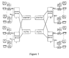
- the present invention relates to Internet technologies, and particularly, to a broadband-narrowband integrated board and a method for testing the board.
- a telephone service and a broadband service may be transferred in a twisted pair simultaneously.
- a signal sent by a user terminal is transferred to a switching network to be switched, the narrowband signal and the broadband signal in the line are to be separated from each other and then respectively transferred to the Public Switched Telephone Network (PSTN) and the Internet to be switched.
- PSTN Public Switched Telephone Network
- the narrowband service and the broadband service are combined and transferred to the user terminal.
- a user at End AL1 is to call another user at End BLn to launch a narrowband service, and meanwhile, the computer at End AL1 is to perform network data interworking with the computer at End DL1 to launch a broadband service, the signal outputted by the computer at End AL1 passes a Remote Terminal Unit (RTU), i.e. the so-called modem, and is combined with the telephone signal by a Splitter (SPL) to generate a broadband narrowband hybrid signal.
- RTU Remote Terminal Unit
- SPL Splitter
- the broadband narrowband hybrid signal is transferred to an access device A, and then the access device A separates the broadband narrowband hybrid signal of End AL1.
- the broadband signal is transferred to the Internet to be switched and routed, reaches another access device D at End DL1 as the destination, and is transferred to the subscriber line of End DL1 after being combined with the narrowband signal transferred to End DL1 in the access device D, and thus the broadband signal reaches the computer at End DL1.
- the narrowband signal is transferred to and switched in the PSTN, and is transferred to a third access device B at End BLn as the destination; the narrowband signal is transferred to the subscriber line of End BLn after being combined with the broadband signal transferred to End BLn in the access device B, and reaches the telephone at End BLn after being separated by the SPL.
- the call to the telephone at End BLn may be put through.
- a service board used in an access device and adopted to handle a broadband service and a narrowband service simultaneously is called a broadband-narrowband integrated board, or an integrated board for short.
- Fig.2 shows a block diagram illustrating a structure of the integrated board. Each board can support services of multiple subscriber lines in general. However, only the service of one subscriber line in the integrated board is shown in Fig.2 .
- the integrated board In an uplink direction, the integrated board first handles the hybrid signal containing a broadband signal denoted as CPE1 and a narrowband signal denoted as PHONE1 sent from the user terminal of subscriber line 1.
- the narrowband signal is separated from the hybrid signal by the SPL, and is sent in sequence to a narrowband user interface circuit 1, a narrowband data processing unit and the narrowband switching network; the broadband signal is sent to the broadband switching network through a broadband service circuit 1 and a broadband data processing unit. It is to be noted that all the subscriber lines supported by an integrated board share one broadband data processing unit and one narrowband data processing unit.
- the operation performed by the integrated board in a downlink direction is opposite to that in the uplink direction.
- the broadband data processing unit distributes data from the broadband switching network to a requested subscriber line; the narrowband data processing unit distributes data from the narrowband switching network to a requested subscriber line.
- the broadband signal B1 and the narrowband signal N1 of the first subscriber line are combined by the SPL and transferred to the subscriber line 1.
- an integrated board corresponds to a signal transit board.
- the integrated board separates the broadband signal and the narrowband signal from the subscriber line from each other, and respectively sends the broadband signal and narrowband signal to the respective switching networks; the integrated board also combines and pairs up the broadband signal and the narrowband signal from the respective switching networks as demanded and then sends the combined signal to the subscriber line.
- An ordinary test method includes connecting the signal to be tested to a dedicated test bus, and testing the signal with a dedicated test board or a dedicated test device connected to the test bus.
- the test for the signal from the subscriber line is called an outgoing test
- the test for the signal from the switching network is called an ingoing test.
- the test is called a net broadband test access.
- the broadband outgoing test in accordance with the prior art affects the narrowband signal, and as a result, the narrowband signal is interrupted. Meanwhile, the narrowband ingoing test cannot be performed in accordance with the prior art.
- the X Digital Subscriber Line (XDSL) service is performed in the telephone line.
- XDSL X Digital Subscriber Line
- each telephone corresponds to one narrowband processing circuit in the narrowband data processing unit, and the number of a telephone is changed if the narrowband processing circuit connected with the telephone is changed. Therefore, the narrowband processing circuit is not required to be changed when a broadband backup is performed.
- the connection path is to be switched so as to ensure the continuity of the service.
- the broadband service circuit 1 and the narrowband user interface circuit 1 respectively provide the broadband service and the narrowband service.
- the broadband service circuit 1 When the broadband service circuit 1 malfunctions and cannot provide the broadband service, for continuing with the broadband service, the broadband service circuit 1 is to be replaced by another broadband service circuit to provide the broadband service to the first subscriber line.
- the process is called the broadband backup.
- the broadband backup in the prior art may result in the interruption of the narrowband signal of the original port.
- Document D1 discloses a circuit for testing POTS service on a shared POTS/DSL carrier.
- the circuit is configured to facilitate testing of the POTS service using an insertion point that is between the DSL filter and the subscriber loop in a manner that is transparent to subscribers.
- Document D2 discloses a relay matrix utilized in a metallic test access systems of DSLAMs, which is used to test the physical disconnection or reconnection of each of the local loops (users).
- Document D3 discloses a DSL splitter providing test access to an interconnected subscriber loop.
- the DSL splitter in a first test mode provides access to allow testing of an interconnected subscriber loop by way of a DSL input.
- a disconnection in series with an associated low pass filter (LPF) disconnects POTS input.
- LPF low pass filter
- Such a splitter may similarly provide access to allow testing of the subscriber loop by way of the POTS input in a second test mode.
- a by-pass by-passes the LPF and a disconnection may disconnect an associated high pass filter (HPF) and DSL input.
- HPF high pass filter
- the present invention provides a broadband-narrowband integrated board and method for testing the board.
- a broadband-narrowband integrated board according to claim 1.
- a method for testing a broadband-narrowband integrated board according to claim 4 :
- Fig.3 shows a schematic diagram illustrating the service when a broadband-narrowband integrated board in accordance with the present invention is in normal operation.
- Fig.3 denotes any of the subscriber lines on the integrated board
- the CPE / PHONE end is connected to a user equipment
- the XDSL end is the broadband interface and is connected to the broadband switching network
- the Subscriber Line Interface Circuit (SLIC) terminal is connected to the narrowband switching network.
- SLIC Subscriber Line Interface Circuit
- a broadband outgoing test switch i.e. the first switching device, which is denoted as KOA in the A th subscriber line
- KOA the first switching device
- KIA the second switching device
- the normally open contact of KOA is connected to a broadband outgoing test bus
- the normally closed contact of KOA is connected to the normally closed contact of KIA
- the normally open contact of KIA is connected to a broadband ingoing test bus.
- the two switches are used for transferring a signal in the subscriber line to the broadband ingoing test bus or the broadband outgoing test bus.
- the narrowband ingoing test switch corresponds to a fourth switching device, which has a normally open contact connected to a narrowband ingoing test bus and a normally closed contact connected to the network end of the subscriber line splitter and protection circuit, i.e. the PRT portion.
- the narrowband outgoing test switch corresponds to a seventh switching device, which has a normally open contact connected to a narrowband outgoing test bus and a normally closed contact connected to the SLIC-A end. The narrowband ingoing test switch is connected with the narrowband outgoing test switch.
- the two switches are used for transferring a narrowband signal to the narrowband outgoing test bus or the narrowband ingoing test bus as needed.
- the user end of the subscriber line splitter and protection circuit i.e. the SPL portion
- the network end of a measuring splitter and protection circuit i.e. the PRT portion
- auxiliary switches K1, K2 and K3, respectively corresponding to a sixth switching device, eighth switching device and third switching device, are set as auxiliary switches for the outgoing test and the ingoing test.
- the auxiliary switch, K1 is located in the narrowband outgoing test bus; the normally open contact of K1 is not connected, and the normally closed contact of K1 is connected to the broadband outgoing test bus.
- the auxiliary switch, K2 is located in the broadband outgoing test bus; the normally closed contact of K2 is not connected, and the normally open contact of K2 is connected to a test device.
- the auxiliary switch, K3, is located in the broadband ingoing test bus; the normally closed contact of K3 is connected to the broadband outgoing test bus, and the normally open contact of K3 is connected to the test device.
- the measuring splitter and protection circuit is also connected to the narrowband ingoing test bus; the user end of the measuring splitter and protection circuit, i.e. the SPL portion, is connected to the broadband ingoing test bus, and the network end of the measuring splitter and protection circuit, i.e. the PRT portion, is connected to the narrowband ingoing test bus.
- the above switching devices and the measuring splitter and protection circuit compose a switching device matrix.
- the above switches may be implemented as relays.
- the narrowband outgoing test switch and the narrowband ingoing test switch may be integrated into one solid relay, which has a much smaller size than a mechanical relay.
- the subscriber line is disconnected from all the test buses, and the broadband outgoing test bus, the narrowband outgoing test bus, the narrowband ingoing test bus and the broadband ingoing test bus are connected to each other.
- the broadband component of the signal having entered the integrated board from the CPE-A / PHONE-A end is directly transferred to the broadband switching network through the XDSL-A end, while the narrowband component of the signal is transferred to the PSTN after passing in sequence through the subscriber line splitter and protection circuit and the SLIC-A end.
- the narrowband signal having entered the integrated board from the PSTN passes the SPL, and is combined with the broadband signal having entered the integrated board from the broadband switching network. The combined signal is transferred to the CPE-A / PHONE-A end of the subscriber line.
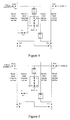
- Fig.4 shows a schematic diagram illustrating the service when a broadband-narrowband integrated board in accordance with the present invention is under a broadband outgoing test.
- the broadband outgoing test switch KOA, the auxiliary switch K2, and the narrowband ingoing test switch of the solid relay S 1 are made to act, that is, these switches are made respectively to turn to the normally open positions.
- the broadband outgoing test bus is connected to the CPE-A / PHONE-A end, which enables the outgoing test for the broadband signal in the signal entering the integrated board from the CPE-A / PHONE-A end.
- the narrowband signal in the signal entering the integrated board from the CPE-A /PHONE-A end passes the broadband outgoing test bus, K2, K3, the measuring splitter and protection circuit, the narrowband ingoing test bus and the solid relay in turn, and eventually is still connected to the SLIC-A end.
- the narrowband service is not affected.
- Fig.5 shows a schematic diagram illustrating the service when a broadband-narrowband integrated board in accordance with the present invention is under a broadband ingoing test.
- the broadband ingoing test switch KIA and the auxiliary switch K3 are made to act, that is, the two switches are made respectively turn to the normally open positions.
- the broadband ingoing test bus is connected to the XDSL-A end, which enables the ingoing test for the broadband signal entering the integrated board from the XDSL-A end.
- the narrowband signal of the A th subscriber line still enters the integrated board from the SLIC-A end, passes the solid relay S1, the subscriber line splitter and protection circuit and broadband outgoing test switch KOA in sequence, and is sent to the user through the CPE-A / PHONE-A end.
- the narrowband service is not affected.
- Fig.6 shows a schematic diagram illustrating the service when a net broadband outgoing test access is performed for a broadband-narrowband integrated board in accordance with the present invention.
- the broadband outgoing test switch KOA and the auxiliary switches K1, K2, and K3 are made respectively turn to the normally open positions.
- the broadband outgoing test bus is connected to the A th subscriber line, which enables the outgoing test for the broadband signal in the A th subscriber line.
- Fig.7 shows a schematic diagram illustrating the service when a broadband-narrowband integrated board in accordance with the present invention is under a narrowband outgoing test.
- the auxiliary switch K2 and the narrowband outgoing test switch of the solid relay S1 are made to act, that is, the switches are made respectively turn to the normally open positions.
- the path for broadband services is not changed, that is, the broadband services are not changed.
- the narrowband signal in the A th subscriber line is transferred to the narrowband outgoing test bus and then to the broadband outgoing test bus, and thus the narrowband signal at the CPE-A / PHONE-A end may be tested through the broadband outgoing test bus.
- Fig.8 shows a schematic diagram illustrating the service when a broadband-narrowband integrated board in accordance with the present invention is under a narrowband ingoing test.
- the auxiliary switch K3 and the narrowband ingoing test switch of the solid relay S1 are made to act, that is, the switches are made respectively turn to the normally open positions.
- the path for broadband services is not changed, that is, the broadband services are not changed.
- the narrowband signal entering the integrated board from the SLIC-A end is transferred via the solid relay to the narrowband ingoing test bus and in turn to the broadband ingoing test bus; thus the narrowband signal at the SLIC-A end may be tested through the broadband ingoing test bus.
- Fig.9 shows a schematic diagram illustrating the service when a broadband-narrowband integrated board in accordance with the present invention is used to perform broadband backup.
- the XDSL-B port When the XDSL-B port malfunctions and cannot provide a broadband service, for continuing with the broadband service of the B th subscriber line, the XDSL-B port is to be replaced by another broadband port to provide the broadband service to the B th subscriber line. It is supposed that the XDSL-A port accomplishes the backup task in Fig.9 .
- the broadband outgoing test switch KOB, the broadband ingoing test switch KIA and the narrowband ingoing test switch of the solid relay S2 are made to act, that is, the switches are made respectively turn to the normally open positions.
- the broadband signal from the XDSL-A end is transferred to the CPE-B / PHONE-B end through the broadband ingoing test switch KIA, the broadband ingoing test bus, the auxiliary switches K3 and K2, the broadband outgoing test bus and the broadband outgoing test switch KOB, which keeps the connection of the broadband service of the B th subscriber line.
- the narrowband signal at the SLIC-B end is transferred to the CPE-B / PHONE-B end through the solid relay S2, the narrowband ingoing test bus, the measuring splitter and protection circuit, the auxiliary switches K3 and K2, and the broadband outgoing test bus, and thus the narrowband service of the B th subscriber line is kept.
- Fig.10 shows a schematic diagram illustrating the service when a broadband-narrowband integrated board in accordance with the present invention is under a broadband ingoing test and a broadband outgoing test simultaneously.
- the connection between the broadband outgoing test bus and the user end of the measuring splitter and protection circuit is to be kept, which may be implemented by directly connecting the broadband outgoing test bus to the user end of the measuring splitter and protection circuit.
- the broadband outgoing test bus and the user end of the measuring splitter and protection circuit may be connected with an auxiliary switch K4, i.e. the fifth switching device.
- the auxiliary switch K4 is located at the user end of the measuring splitter and protection circuit, the normally open contact of the auxiliary switch K4 is connected to the broadband outgoing test bus, and the normally closed contact of the auxiliary switch K4 is not connected.
- the broadband outgoing test switch KOA, the broadband ingoing test switch KIA and the auxiliary switches K2 and K3, are made to act, that is, the switches are made respectively turn to the normally open positions,.
- the broadband signal from the CPE-A / PHONE-A end is transferred to the outgoing test bus while the broadband signal from the XDSL-A end is transferred to the ingoing test bus.
- the broadband outgoing test and the broadband ingoing test may be performed simultaneously.
- the auxiliary switch K4 and the narrowband ingoing test switch of the solid relay S1 are made respectively turn to the normally open positions.
- the CPE-A / PHONE-A end is connected to the SLIC-A end through the broadband outgoing test switch KOA, the broadband outgoing test bus, the auxiliary switch K4, the measuring splitter and protection circuit, the narrowband ingoing test bus and the solid relay, and the connection of the narrowband service is kept.
- the auxiliary switch K4 is made turn to the normally closed position.
- the present invention also provides a method for testing the broadband-narrowband integrated board corresponding to the above broadband-narrowband integrated board with the test function.
- the method includes the following processes.
- the test buses include a broadband outgoing test bus, a broadband ingoing test bus, a narrowband outgoing test bus and a narrowband ingoing test bus.
- the process of setting the switching device matrix includes the following.
- a broadband outgoing test switch KOA is set at the CPE / PHONE end of the subscriber line; and a broadband ingoing test switch KIA is set at the XDSL end of the subscriber line.
- the normally open contact of KOA is connected to the broadband outgoing test bus, the normally closed contact of KOA is connected to the normally closed contact of KIA, and the normally open contact of KIA is connected to the broadband ingoing test bus.
- Two switches in series are set between the SLIC end of the subscriber line and the subscriber line splitter and protection circuit, and are respectively called as a narrowband ingoing test switch and a narrowband outgoing test switch.
- the normally open contact of the narrowband ingoing test switch is connected to the narrowband ingoing test bus while the normally closed contact of the narrowband ingoing test switch is connected to the network end of the subscriber line splitter and protection circuit, i.e. the PRT portion.
- the normally open contact of the narrowband outgoing test switch is connected to the narrowband outgoing test bus while the normally closed contact of the narrowband outgoing test switch is connected to the SLIC-A end.
- the narrowband ingoing test switch is connected to the narrowband outgoing test switch.
- the narrowband outgoing test switch and the narrowband ingoing test switch may be integrated into one solid relay.
- An auxiliary switch K1 is set in the narrowband outgoing test bus.
- the normally open contact of K1 is not connected, and the normally closed contact of K1 is connected to the broadband outgoing test bus.
- An auxiliary switch K2 is set in the broadband outgoing test bus, the normally closed contact of K2 is not connected, and the normally open contact of K2 is connected to a test device.
- An auxiliary switch K3 is set in the broadband ingoing test bus, the normally closed contact of K3 is connected to the broadband outgoing test bus, and the normally open contact of K3 is connected to the test device.
- a measuring splitter and protection circuit is set in the narrowband ingoing test bus, the user end of the SPL+PRT, i.e. the SPL portion, is connected to the broadband ingoing test bus, and the network end of the SPL+PRT, i.e. the PRT portion, is connected to the narrowband ingoing test bus.
- the broadband outgoing test switch KOA, the auxiliary switch K2 and the narrowband ingoing test switch of the solid relay S1 are made to act, that is, the switches are made turn to the normally open positions.
- the broadband uplink signal enters the test device through the broadband outgoing test bus.
- the broadband outgoing test bus and the narrowband ingoing test bus are connected through the measuring splitter and protection circuit; the network end of the measuring splitter and protection circuit is connected to the narrowband ingoing test bus and user end of the measuring splitter and protection circuit is connected to the broadband outgoing test bus.
- the narrowband ingoing test bus is connected to the SLIC.
- the service signal to be tested is a broadband downlink signal, that is, the broadband ingoing test is to be performed for the integrated board
- the broadband ingoing test switch KIA and the auxiliary switch K3 are made to act, that is, the switches are made turn to the normally open positions.
- the broadband downlink signal enters the test device through the broadband ingoing test bus. Meanwhile, the path for narrowband services in normal operation is used continuously to perform the narrowband service.
- the broadband outgoing test switch KOA and the auxiliary switches K1, K2, and K3 are made turn to the normally open positions. Thereby, the broadband uplink signal enters the test device through the broadband outgoing test bus. Meanwhile, the narrowband service is disconnected as required in net broadband outgoing test access.
- the service signal to be tested is a narrowband uplink signal, that is, the narrowband outgoing test is to be performed for the integrated board
- the auxiliary switch K2 and the narrowband outgoing test switch of the solid relay S1 are made to act, that is, the switches are made turn to the normally open positions.
- the narrowband outgoing test bus is connected to the broadband outgoing test bus; the narrowband uplink signal enters the test device through the narrowband outgoing test bus and the broadband outgoing test bus. Meanwhile, the path for broadband services in normal operation is used continuously to perform the broadband service.
- the service signal to be tested is a narrowband downlink signal, that is, the narrowband ingoing test is to be performed for the integrated board
- the auxiliary switch K3 and the narrowband ingoing test switch of the solid relay S 1 are made to act, that is, the switches are made turn to the normally open positions.
- the narrowband ingoing test bus and the broadband ingoing test bus are connected to each other by the measuring splitter and protection circuit; the user end of the measuring splitter and protection circuit is connected to the broadband ingoing test bus, and network end of the measuring splitter and protection circuit is connected to the narrowband ingoing test bus.
- the SLIC is connected to the narrowband ingoing test bus and thus the narrowband downlink signal enters the test device through the narrowband ingoing test bus, the measuring splitter and protection circuit and the broadband ingoing test bus. Meanwhile, the path for broadband services in normal operation is used continuously to perform the broadband service.
- the broadband uplink signal and broadband downlink signal are to enter the test device respectively through the broadband outgoing test bus and the broadband ingoing test bus.
- the broadband ingoing test bus and the narrowband ingoing test bus are connected through the measuring splitter and protection circuit: the user end of the measuring splitter and protection circuit is connected to the broadband ingoing test bus and the network end of the measuring splitter and protection circuit is connected to the narrowband ingoing test bus. The user end of the measuring splitter and protection circuit is also connected to the broadband outgoing test bus.
- the SLIC is connected to the narrowband ingoing test bus.
- the user end of the measuring splitter and protection circuit may be connected to the broadband outgoing test bus directly or via an auxiliary switch K4.
- the auxiliary switch K4 is set at the user end of the measuring splitter and protection circuit and has a normally open contact connected to the broadband outgoing test bus and a normally closed contact not connected.
- the broadband outgoing test switch KOA the broadband ingoing test switch KIA
- the narrowband ingoing test switch of the solid relay S1 the auxiliary switches K2, K3 and K4 are made to act, that is, the switches are made turn to the normally open positions.
- the auxiliary switch K4 is kept in the normally closed position when a normal service is being performed or a signal to be tested does not contain both the broadband downlink signal and the broadband uplink signal at the same time.
- the broadband interface of the original subscriber line malfunctions after the process a
- the broadband interface of a backup subscriber line is used to keep on providing the broadband service to the original subscriber line. It is assumed that the broadband outgoing test switch of the original subscriber line is KOB, and the solid relay between the SLIC end of the original subscriber line and the subscriber line splitter and protection circuit of the original subscriber line is S2.
- the KOB, KIA and the narrowband ingoing test switch of the solid relay S2 are made turn to the normally open positions so that, the broadband interface of the backup subscriber line is connected to the broadband ingoing test bus, the CPE/PHONE end of the original subscriber line is connected to the broadband outgoing test bus, and the broadband ingoing test bus is connected to the broadband outgoing test bus, and thus a new broadband service path is formed; meanwhile, the narrowband ingoing test bus is connected to the broadband ingoing test bus by the measuring splitter and protection circuit, where the user end of the measuring splitter and protection circuit is connected to the broadband ingoing test bus and the network end of the measuring splitter and protection circuit is connected to the narrowband ingoing test bus, and the SLIC of the original subscriber line is connected to the narrowband ingoing test bus, and thus a new narrowband service path is formed.
Landscapes
- Engineering & Computer Science (AREA)
- Signal Processing (AREA)
- Monitoring And Testing Of Exchanges (AREA)
- Structure Of Telephone Exchanges (AREA)
Claims (12)
- Integrierte Breitband-Schmalband-Karte, die Folgendes umfasst:einen Testbus, um ein Dienstsignal mit einer Testvorrichtung zu verbinden; undeine Schaltvorrichtungsmatrix, um den Testbus mit einer Teilnehmerleitung zu verbinden, um zu bewirken, dass ein zu testendes Dienstsignal, das entweder ein Breitbandsignal oder ein Schmalbandsignal ist, in den Testbus eingegeben wird,dadurch gekennzeichnet, dass
der Testbus Folgendes umfasst:einen ausgehenden Breitband-Testbus, einen eingehenden Breitband-Testbus, einen ausgehenden Schmalband-Testbus und einen eingehenden Schmalband-Testbus, und dass die Schaltvorrichtungsmatrix Folgendes umfasst:eine erste Schaltvorrichtung (KOA), die mit einem Anwenderendgerät verbunden ist und von der ein normalerweise offener Kontakt mit dem ausgehenden Breitband-Testbus verbunden ist und ein normalerweise geschlossener Kontakt mit einem normalerweise geschlossenen Kontakt einer zweiten Schaltvorrichtung (KIA) verbunden ist;die zweite Schaltvorrichtung (KIA), die mit einer Breitband-Schnittstelle verbunden ist und von der ein normalerweise offener Kontakt mit dem eingehenden Breitband-Testbus verbunden ist;eine dritte Schaltvorrichtung (K3), die mit dem eingehenden Breitband-Testbus verbunden ist und von der ein normalerweise offener Kontakt mit der Testvorrichtung verbunden ist und ein normalerweise geschlossener Kontakt mit dem ausgehenden Breitband-Testbus verbunden ist;eine vierte Schaltvorrichtung, die mit einer siebenten Schaltvorrichtung verbunden ist und von der ein normalerweise offener Kontakt mit dem eingehenden Schmalband-Testbus verbunden ist und ein normalerweise geschlossener Kontakt mit einer Teilnehmerleitungs-Splitter- und Schutzschaltung verbunden ist;eine sechste Schaltvorrichtung (K1), die mit dem ausgehenden Schmalband-Testbus verbunden ist und von der ein normalerweise offener Kontakt nicht angeschlossen ist und ein normalerweise geschlossener Kontakt mit dem ausgehenden Breitband-Testbus verbunden ist;die siebente Schaltvorrichtung, von der ein normalerweise offener Kontakt mit dem ausgehenden Schmalband-Testbus verbunden ist und ein normalerweise geschlossener Kontakt mit einer Teilnehmerleitungs-Schnittstellenschaltung verbunden ist;eine achte Schaltvorrichtung (K2), die mit dem ausgehenden Breitband-Testbus verbunden ist und von der ein normalerweise offener Kontakt mit der Testvorrichtung verbunden ist und ein normalerweise geschlossener Kontakt nicht angeschlossen ist;eine Messsplitter- und Schutzschaltung, von der ein Anwenderende mit dem eingehenden Breitband-Testbus verbunden ist und ein Netzende mit dem eingehenden Schmalband-Testbus verbunden ist. - Integrierte Breitband-Schmalband-Karte nach Anspruch 1, die ferner Folgendes umfasst:eine fünfte Schaltvorrichtung, die mit dem Anwenderende der Messsplitter- und Schutzschaltung verbunden ist und von der ein normalerweise offener Kontakt mit dem ausgehenden Breitband-Testbus verbunden ist und ein normalerweise geschlossener Kontakt nicht angeschlossen ist.
- Integrierte Breitband-Schmalband-Karte nach Anspruch 1 oder 2, wobei die vierte Schaltvorrichtung und die siebte Schaltvorrichtung als ein Halbleiterrelais integriert sind.
- Verfahren zum Testen einer integrierten Breitband-Schmalband-Karte, das Folgendes umfasst:Setzen eines Testbusses und einer Schaltvorrichtungsmatrix auf der integrierten Breitband-Schmalband-Karte;wahlweises Verbinden des Testbusses mit einer Teilnehmerleitung unter Verwendung der Schaltvorrichtungsmatrix, um zu bewirken, dass ein zu testendes Dienstsignal, das entweder ein Breitbandsignal oder ein Schmalbandsignal ist, in den Testbus eingegeben wird; undTesten des zu testenden Signals durch den Testbus,dadurch gekennzeichnet, dass
der Prozess des Setzens des Testbusses auf der integrierten Breitband-Schmalband-Karte Folgendes umfasst:Setzen eines ausgehenden Breitband-Testbusses, eines eingehenden Breitband-Testbusses, eines ausgehenden Schmalband-Testbusses und eines eingehenden Schmalband-Testbusses auf der integrierten Breitband-Schmalband-Karte, unddass der Prozess des Setzens der Schaltvorrichtungsmatrix auf der integrierten Breitband-Schmalband-Karte Folgendes umfasst:Setzen einer ersten Schaltvorrichtung, die mit einem Anwenderendgerät verbunden ist, und Verbinden eines normalerweise offenen Kontakts und eines normalerweise geschlossenen Kontakts der ersten Schaltvorrichtung mit dem ausgehenden Breitband-Testbus bzw. mit einem normalerweise geschlossenen Kontakt einer zweiten Schaltvorrichtung;Setzen der zweiten Schaltvorrichtung, die mit der Breitband-Schnittstelle verbunden ist, und Verbinden eines normalerweise offenen Kontakts der zweiten Schaltvorrichtung mit dem eingehenden Schmalband-Testbus;Setzen einer dritten Schaltvorrichtung, die mit dem eingehenden Breitband-Testbus verbunden ist, und Verbinden eines normalerweise offenen Kontakts und eines normalerweise geschlossenen Kontakts der dritten Schaltvorrichtung mit dem Testbus bzw. mit dem ausgehenden Breitband-Testbus;Setzen einer vierten Schaltvorrichtung, die mit einer siebenten Schaltvorrichtung verbunden ist, und Verbinden eines normalerweise offenen Kontakts und eines normalerweise geschlossenen Kontakts der vierten Schaltvorrichtung mit dem eingehenden Schmalband-Testbus bzw. mit einer Teilnehmerleitungs-Splitter- und Schutzschaltung;Setzen einer sechsten Schaltvorrichtung, die mit dem ausgehenden Schmalband-Testbus verbunden ist, und Nicht-angeschlossen-Lassen eines normalerweise offenen Kontakts der sechsten Schaltvorrichtung und Verbinden eines normalerweise geschlossenen Kontakts der sechsten Schaltvorrichtung mit dem ausgehenden Breitband-Testbus;Setzen der siebenten Schaltvorrichtung, die mit der vierten Schaltvorrichtung verbunden ist, und Verbinden eines normalerweise offenen Kontakts und eines normalerweise geschlossenen Kontakts der siebenten Schaltvorrichtung mit dem eingehenden Schmalband-Testbus bzw. mit einer Teilnehmerleitungs-Schnittstellenschaltung;Setzen einer achten Schaltvorrichtung, die mit dem ausgehenden Breitband-Testbus verbunden ist, und Verbinden eines normalerweise offenen Kontakts der achten Schaltvorrichtung mit der Testvorrichtung und Nicht-angeschlossen-Lassen eines normalerweise geschlossenen Kontakts der achten Schaltvorrichtung;Setzen einer Messsplitter- und Schutzschaltung und Verbinden eines Anwenderendes und eines Netzendes der Messsplitter- und Schutzschaltung mit dem eingehenden Breitband-Testbus bzw. mit dem eingehenden Schmalband-Testbus. - Verfahren nach Anspruch 4, wobei in dem Fall, in dem das zu testende Dienstsignal ein Breitband-Aufwärtsstreckensignal ist, das Verbinden des Testbusses mit der Teilnehmerleitung, um zu bewirken, dass das zu testende Dienstsignal in den Testbus eingegeben wird, Folgendes umfasst:Bewirken, dass die erste Schaltvorrichtung, die achte Schaltvorrichtung und die vierte Schaltvorrichtung in die normalerweise offenen Positionen gehen und folglich bewirken: dassdas Breitband-Aufwärtsstreckensignal durch den ausgehenden Breitband-Testbus in die Testvorrichtung eingegeben wird;das Netzende und das Anwenderende der Messsplitter- und Schutzschaltung mit dem eingehenden Schmalband-Testbus bzw. mit dem ausgehenden Breitband-Testbus verbunden werden; undder eingehende Schmalband-Testbus mit der Teilnehmerleitungs-Schnittstellenschaltung verbunden wird.
- Verfahren nach Anspruch 4, wobei in dem Fall, in dem das zu testende Dienstsignal ein Breitband-Abwärtsstreckensignal ist, das Verbinden des Testbusses mit der Teilnehmerleitung, um zu bewirken, dass das zu testende Dienstsignal in den Testbus eingegeben wird, Folgendes umfasst:Bewirken, dass die zweite Schaltvorrichtung und die dritte Schaltvorrichtung in die normalerweise offenen Positionen gehen und folglich bewirken: dass das Breitband-Abwärtsstreckensignal durch den eingehenden Breitband-Testbus in die Testvorrichtung eingegeben wird; undder Schmalbanddienst durch einen Schmalband-Dienstweg im Normalbetrieb kontinuierlich ausgeführt wird.
- Verfahren nach Anspruch 4, wobei in dem Fall, in dem das zu testende Dienstsignal ein Breitband-Aufwärtsstreckensignal ist, nachdem der Schmalbanddienst unterbrochen worden ist, das Verbinden des Testbusses mit der Teilnehmerleitung, um zu bewirken, dass das zu testende Dienstsignal in den Testbus eingegeben wird, Folgendes umfasst:Bewirken, dass die erste Schaltvorrichtung, die dritte Schaltvorrichtung, die sechste Schaltvorrichtung und die achte Schaltvorrichtung in die normalerweise offenen Positionen gehen und folglich bewirken: dassdas Breitband-Aufwärtsstreckensignal durch den ausgehenden Breitband-Testbus in die Testvorrichtung eingegeben wird.
- Verfahren nach Anspruch 4, wobei in dem Fall, in dem das zu testende Dienstsignal ein Schmalband-Aufwärtsstreckensignal ist, das Verbinden des Testbusses mit der Teilnehmerleitung, um zu bewirken, dass das zu testende Dienstsignal in den Testbus eingegeben wird, Folgendes umfasst:Bewirken, dass die achte Schaltvorrichtung und die siebente Schaltvorrichtung in die normalerweise offenen Positionen gehen und folglich bewirken: dass der ausgehende Schmalband-Testbus mit dem ausgehenden Breitband-Testbus verbunden wird;das Schmalband-Aufwärtsstreckensignal durch den ausgehenden Schmalband-Testbus und den ausgehenden Breitband-Testbus in die Testvorrichtung eingegeben wird; undder Breitbanddienst durch einen Breitband-Dienstweg im Normalbetrieb kontinuierlich ausgeführt wird.
- Verfahren nach Anspruch 4, wobei in dem Fall, in dem das zu testende Dienstsignal ein Schmalband-Abwärtsstreckensignal ist, das Verbinden des Testbusses mit der Teilnehmerleitung, um zu bewirken, dass das zu testende Dienstsignal in den Testbus eingegeben wird, Folgendes umfasst:Bewirken, dass die dritte Schaltvorrichtung und die vierte Schaltvorrichtung in die normalerweise offenen Positionen gehen und folglich bewirken: dass das Anwenderende und das Netzende der Messsplitter- und Schutzschaltung mit dem eingehenden Breitband-Testbus bzw. mit dem eingehenden Schmalband-Testbus verbunden werden;die Teilnehmerleitungs-Schnittstellenschaltung mit dem eingehenden Schmalband-Testbus verbunden wird, so dass das Schmalband-Abwärtsstreckensignal durch den eingehenden Schmalband-Testbus, die Messsplitter- und Schutzschaltung und den eingehenden Breitband-Testbus in die Testvorrichtung eingegeben wird; undder Breitbanddienst durch einen Breitband-Dienstweg des Normalbetriebs kontinuierlich ausgeführt wird.
- Verfahren nach Anspruch 4, wobei das Setzen der Schaltvorrichtungsmatrix auf der integrierten Breitband-Schmalband-Karte ferner Folgendes umfasst:Setzen einer fünften Schaltvorrichtung, die mit dem Anwenderende der Messsplitter - und Schutzschaltung verbunden ist, und Verbinden eines normalerweise offenen Kontakts der fünften Schaltvorrichtung mit dem ausgehenden Breitband-Testbus undNicht-angeschlossen-Lassen eines normalerweise geschlossenen Kontakts der fünften Schaltvorrichtung; undwobei in dem Fall, in dem das zu testende Dienstsignal ein Breitband-Abwärtsstreckensignal und ein Breitband-Aufwärtsstreckensignal enthält, das Verbinden des Testbusses mit der Teilnehmerleitung, um zu bewirken, dass das zu testende Dienstsignal in den Testbus eingegeben wird, Folgendes umfasst:Bewirken, dass die erste Schaltvorrichtung, die zweite Schaltvorrichtung, die dritte Schaltvorrichtung, die fünfte Schaltvorrichtung und die achte Schaltvorrichtung in die normalerweise offenen Positionen gehen und folglich bewirken: dass das Breitband-Aufwärtsstreckensignal und das Breitband-Abwärtsstreckensignal durch den ausgehenden Breitband-Testbus bzw. durch den eingehenden Breitband-Testbus in die Testvorrichtung eingegeben werden;das Anwenderende und das Netzende der Messsplitter- und Schutzschaltung mit dem ausgehenden Breitband-Testbus bzw. mit dem eingehenden Schmalband-Testbus verbunden werden; unddie Teilnehmerleitungs-Schnittstellenschaltung mit dem eingehenden Schmalband-Testbus verbunden wird, um einen Schmalband-Dienstweg zu bilden.
- Verfahren nach Anspruch 4, das ferner Folgendes umfasst:wenn die Breitband-Schnittstelle einer ursprünglichen Teilnehmerleitung ausfällt, Verwenden der Breitbandschnittstelle einer Sicherungs-Teilnehmerleitung, um der ursprünglichen Teilnehmerleitung den Breitbanddienst bereitzustellen.
- Verfahren nach Anspruch 11, wobei das Verwenden der Breitbandschnittstelle der Sicherungs-Teilnehmerleitung, um der ursprünglichen Teilnehmerleitung den Breitbanddienst bereitzustellen, Folgendes umfasst:Bewirken, dass die erste Schaltvorrichtung der ursprünglichen Teilnehmerleitung, die zweite Schaltvorrichtung der Sicherungs-Teilnehmerleitung und die vierte Schaltvorrichtung der ursprünglichen Teilnehmerleitung in die normalerweise offenen Positionen gehen und folglich bewirken: dassdie Breitbandschnittstelle der Sicherungs-Teilnehmerleitung mit dem eingehenden Breitband-Testbus verbunden wird, das Anwenderendgerät der ursprünglichen Teilnehmerleitung mit dem ausgehenden Breitband-Testbus verbunden wird und der eingehende Breitband-Testbus mit dem ausgehenden Breitband-Testbus verbunden wird, um einen neuen Breitband-Dienstweg zu bilden; unddas Anwenderende und das Netzende der Messsplitter- und Schutzschaltung mit dem eingehenden Breitband-Testbus bzw. mit dem eingehenden Schmalband-Testbus verbunden werden und die Teilnehmerleitungs-Schnittstellenschaltung der ursprünglichen Teilnehmerleitung mit dem eingehenden Schmalband-Testbus verbunden wird, um einen neuen Schmalband-Dienstweg zu bilden.
Applications Claiming Priority (2)
| Application Number | Priority Date | Filing Date | Title |
|---|---|---|---|
| CNB2005101210648A CN100531256C (zh) | 2005-12-20 | 2005-12-20 | 具有测试功能的宽窄带合一板及测试方法 |
| PCT/CN2006/002760 WO2007071146A1 (en) | 2005-12-20 | 2006-10-18 | A broad-narrow band integrated board and method for testing said board |
Publications (3)
| Publication Number | Publication Date |
|---|---|
| EP1906546A1 EP1906546A1 (de) | 2008-04-02 |
| EP1906546A4 EP1906546A4 (de) | 2009-01-14 |
| EP1906546B1 true EP1906546B1 (de) | 2012-12-12 |
Family
ID=37298329
Family Applications (1)
| Application Number | Title | Priority Date | Filing Date |
|---|---|---|---|
| EP06804978A Not-in-force EP1906546B1 (de) | 2005-12-20 | 2006-10-18 | Ein breit-schmalband integrierter schaltkreis und prüfungsverfahren eines solchen schaltkreises |
Country Status (4)
| Country | Link |
|---|---|
| EP (1) | EP1906546B1 (de) |
| CN (2) | CN100531256C (de) |
| ES (1) | ES2397930T3 (de) |
| WO (1) | WO2007071146A1 (de) |
Families Citing this family (2)
| Publication number | Priority date | Publication date | Assignee | Title |
|---|---|---|---|---|
| CN101079920B (zh) * | 2007-06-28 | 2011-11-23 | 中兴通讯股份有限公司 | 具有测试功能的窄带用户板及用户线路自动测试方法 |
| TWI520561B (zh) * | 2012-11-09 | 2016-02-01 | 緯創資通股份有限公司 | 測試板 |
Family Cites Families (7)
| Publication number | Priority date | Publication date | Assignee | Title |
|---|---|---|---|---|
| CN1108043C (zh) * | 1999-12-31 | 2003-05-07 | 西安交通大学 | 窄带与宽带综合接入设备 |
| US6785325B1 (en) * | 2000-06-07 | 2004-08-31 | Nortel Networks Limited | DSL splitter providing test access to an interconnected subscriber loop and method |
| US7068758B1 (en) * | 2000-10-23 | 2006-06-27 | Alcatel Canada Inc. | Integrated metallic access for high port density DSLAM |
| US6618469B2 (en) * | 2002-02-05 | 2003-09-09 | Adc Dsl Systems, Inc. | Circuits and methods for testing POTS service |
| CN1194557C (zh) * | 2003-08-29 | 2005-03-23 | 华为技术有限公司 | 用于xDSL和窄带交换接入的总配线架方法及装置 |
| CN100341286C (zh) * | 2004-02-21 | 2007-10-03 | 华为技术有限公司 | 在业务单板内/间实现中心局仿真测试的方法及系统 |
| CN1674458B (zh) * | 2004-03-23 | 2010-11-03 | 华为技术有限公司 | 数字用户线路的测试方法及局端宽带设备 |
-
2005
- 2005-12-20 CN CNB2005101210648A patent/CN100531256C/zh not_active Expired - Fee Related
-
2006
- 2006-10-18 CN CNA200680011682XA patent/CN101156326A/zh active Pending
- 2006-10-18 EP EP06804978A patent/EP1906546B1/de not_active Not-in-force
- 2006-10-18 WO PCT/CN2006/002760 patent/WO2007071146A1/zh not_active Ceased
- 2006-10-18 ES ES06804978T patent/ES2397930T3/es active Active
Also Published As
| Publication number | Publication date |
|---|---|
| WO2007071146A1 (en) | 2007-06-28 |
| ES2397930T3 (es) | 2013-03-12 |
| CN1859468A (zh) | 2006-11-08 |
| CN100531256C (zh) | 2009-08-19 |
| EP1906546A4 (de) | 2009-01-14 |
| CN101156326A (zh) | 2008-04-02 |
| EP1906546A1 (de) | 2008-04-02 |
Similar Documents
| Publication | Publication Date | Title |
|---|---|---|
| JP3905733B2 (ja) | 加入者回線テストシステム及びその方法 | |
| US6470074B2 (en) | System and method for providing data and voice services on a shared line | |
| US6546089B1 (en) | Method and system for supporting a lifeline associated with voice over DSL | |
| US6594343B1 (en) | Splitter bypass architecture for testing multiple ports | |
| TW518898B (en) | Systems and methods for electronically managing digital subscriber line (DSL) telecommunications connections | |
| CN100466535C (zh) | 实现用户在ip网络与pstn之间切换的装置及其方法 | |
| JP2002232562A (ja) | 通信システム用ラインカード、potsと非対称dsラインサービスと対称dsラインサービスをラインカードに基づいてサポートする方法 | |
| CN100353680C (zh) | 实现多级通信设备备份的装置及其主备倒换的方法 | |
| EP1373911A1 (de) | Pots-erweiterungsvorrichtung für voice-fallback in einem teilnehmeranschluss gebiet der erfindung | |
| EP1906546B1 (de) | Ein breit-schmalband integrierter schaltkreis und prüfungsverfahren eines solchen schaltkreises | |
| US7688744B2 (en) | Broadband test line access circuit, broadband test-line access board and broadband test device | |
| US7801025B2 (en) | Method and system for implementing standby | |
| CN101854562A (zh) | 实现总配线架的方法及总配线架 | |
| US7039732B1 (en) | Method and apparatus for providing redundancy between card elements in a chassis | |
| US20140247934A1 (en) | Method and Apparatus for Communication Having Critically Assured Services | |
| CN100466663C (zh) | 一种xDSL测试方法 | |
| EP1903832B1 (de) | Verfahren und System zur Signalteilung und Signalteilungsvorrichtung | |
| EP1565031B1 (de) | Redundanzsystem und -Verfahren für einen DSLAM | |
| WO2008025296A1 (fr) | Carte unique d'accès intégrée permettant d'accéder à de multiples services | |
| WO2009036668A1 (fr) | Reseau de communication, repartiteur, procede de communication et procede d'installation de repartiteur | |
| JPH04122162A (ja) | 端末系装置側自己診断方式 | |
| TWI276326B (en) | A system and method for digital subscriber loop access multiplexer | |
| TW519813B (en) | Public branch exchange system with multiple emergency lines | |
| US20080075093A1 (en) | Subscriber card | |
| CN100505799C (zh) | 一种4线n+1备份及其测试电路 |
Legal Events
| Date | Code | Title | Description |
|---|---|---|---|
| PUAI | Public reference made under article 153(3) epc to a published international application that has entered the european phase |
Free format text: ORIGINAL CODE: 0009012 |
|
| 17P | Request for examination filed |
Effective date: 20080218 |
|
| AK | Designated contracting states |
Kind code of ref document: A1 Designated state(s): AT BE BG CH CY CZ DE DK EE ES FI FR GB GR HU IE IS IT LI LT LU LV MC NL PL PT RO SE SI SK TR |
|
| DAX | Request for extension of the european patent (deleted) | ||
| A4 | Supplementary search report drawn up and despatched |
Effective date: 20081215 |
|
| 17Q | First examination report despatched |
Effective date: 20090402 |
|
| REG | Reference to a national code |
Ref country code: DE Ref legal event code: R079 Ref document number: 602006033616 Country of ref document: DE Free format text: PREVIOUS MAIN CLASS: H04B0003460000 Ipc: H04M0003220000 |
|
| GRAP | Despatch of communication of intention to grant a patent |
Free format text: ORIGINAL CODE: EPIDOSNIGR1 |
|
| RIC1 | Information provided on ipc code assigned before grant |
Ipc: H04M 3/30 20060101ALI20120605BHEP Ipc: H04M 3/00 20060101ALI20120605BHEP Ipc: H04M 7/00 20060101ALI20120605BHEP Ipc: H04M 3/22 20060101AFI20120605BHEP |
|
| DAX | Request for extension of the european patent (deleted) | ||
| GRAS | Grant fee paid |
Free format text: ORIGINAL CODE: EPIDOSNIGR3 |
|
| GRAA | (expected) grant |
Free format text: ORIGINAL CODE: 0009210 |
|
| AK | Designated contracting states |
Kind code of ref document: B1 Designated state(s): AT BE BG CH CY CZ DE DK EE ES FI FR GB GR HU IE IS IT LI LT LU LV MC NL PL PT RO SE SI SK TR |
|
| REG | Reference to a national code |
Ref country code: GB Ref legal event code: FG4D |
|
| REG | Reference to a national code |
Ref country code: CH Ref legal event code: EP |
|
| REG | Reference to a national code |
Ref country code: AT Ref legal event code: REF Ref document number: 588817 Country of ref document: AT Kind code of ref document: T Effective date: 20121215 |
|
| REG | Reference to a national code |
Ref country code: IE Ref legal event code: FG4D |
|
| REG | Reference to a national code |
Ref country code: DE Ref legal event code: R096 Ref document number: 602006033616 Country of ref document: DE Effective date: 20130131 |
|
| REG | Reference to a national code |
Ref country code: NL Ref legal event code: T3 |
|
| REG | Reference to a national code |
Ref country code: ES Ref legal event code: FG2A Ref document number: 2397930 Country of ref document: ES Kind code of ref document: T3 Effective date: 20130312 |
|
| PG25 | Lapsed in a contracting state [announced via postgrant information from national office to epo] |
Ref country code: SE Free format text: LAPSE BECAUSE OF FAILURE TO SUBMIT A TRANSLATION OF THE DESCRIPTION OR TO PAY THE FEE WITHIN THE PRESCRIBED TIME-LIMIT Effective date: 20121212 Ref country code: LT Free format text: LAPSE BECAUSE OF FAILURE TO SUBMIT A TRANSLATION OF THE DESCRIPTION OR TO PAY THE FEE WITHIN THE PRESCRIBED TIME-LIMIT Effective date: 20121212 Ref country code: FI Free format text: LAPSE BECAUSE OF FAILURE TO SUBMIT A TRANSLATION OF THE DESCRIPTION OR TO PAY THE FEE WITHIN THE PRESCRIBED TIME-LIMIT Effective date: 20121212 |
|
| REG | Reference to a national code |
Ref country code: AT Ref legal event code: MK05 Ref document number: 588817 Country of ref document: AT Kind code of ref document: T Effective date: 20121212 |
|
| REG | Reference to a national code |
Ref country code: LT Ref legal event code: MG4D |
|
| PG25 | Lapsed in a contracting state [announced via postgrant information from national office to epo] |
Ref country code: SI Free format text: LAPSE BECAUSE OF FAILURE TO SUBMIT A TRANSLATION OF THE DESCRIPTION OR TO PAY THE FEE WITHIN THE PRESCRIBED TIME-LIMIT Effective date: 20121212 Ref country code: GR Free format text: LAPSE BECAUSE OF FAILURE TO SUBMIT A TRANSLATION OF THE DESCRIPTION OR TO PAY THE FEE WITHIN THE PRESCRIBED TIME-LIMIT Effective date: 20130313 Ref country code: LV Free format text: LAPSE BECAUSE OF FAILURE TO SUBMIT A TRANSLATION OF THE DESCRIPTION OR TO PAY THE FEE WITHIN THE PRESCRIBED TIME-LIMIT Effective date: 20121212 |
|
| PG25 | Lapsed in a contracting state [announced via postgrant information from national office to epo] |
Ref country code: EE Free format text: LAPSE BECAUSE OF FAILURE TO SUBMIT A TRANSLATION OF THE DESCRIPTION OR TO PAY THE FEE WITHIN THE PRESCRIBED TIME-LIMIT Effective date: 20121212 Ref country code: CZ Free format text: LAPSE BECAUSE OF FAILURE TO SUBMIT A TRANSLATION OF THE DESCRIPTION OR TO PAY THE FEE WITHIN THE PRESCRIBED TIME-LIMIT Effective date: 20121212 Ref country code: BG Free format text: LAPSE BECAUSE OF FAILURE TO SUBMIT A TRANSLATION OF THE DESCRIPTION OR TO PAY THE FEE WITHIN THE PRESCRIBED TIME-LIMIT Effective date: 20130312 Ref country code: IS Free format text: LAPSE BECAUSE OF FAILURE TO SUBMIT A TRANSLATION OF THE DESCRIPTION OR TO PAY THE FEE WITHIN THE PRESCRIBED TIME-LIMIT Effective date: 20130412 Ref country code: AT Free format text: LAPSE BECAUSE OF FAILURE TO SUBMIT A TRANSLATION OF THE DESCRIPTION OR TO PAY THE FEE WITHIN THE PRESCRIBED TIME-LIMIT Effective date: 20121212 Ref country code: SK Free format text: LAPSE BECAUSE OF FAILURE TO SUBMIT A TRANSLATION OF THE DESCRIPTION OR TO PAY THE FEE WITHIN THE PRESCRIBED TIME-LIMIT Effective date: 20121212 |
|
| PG25 | Lapsed in a contracting state [announced via postgrant information from national office to epo] |
Ref country code: RO Free format text: LAPSE BECAUSE OF FAILURE TO SUBMIT A TRANSLATION OF THE DESCRIPTION OR TO PAY THE FEE WITHIN THE PRESCRIBED TIME-LIMIT Effective date: 20121212 Ref country code: PT Free format text: LAPSE BECAUSE OF FAILURE TO SUBMIT A TRANSLATION OF THE DESCRIPTION OR TO PAY THE FEE WITHIN THE PRESCRIBED TIME-LIMIT Effective date: 20130412 Ref country code: PL Free format text: LAPSE BECAUSE OF FAILURE TO SUBMIT A TRANSLATION OF THE DESCRIPTION OR TO PAY THE FEE WITHIN THE PRESCRIBED TIME-LIMIT Effective date: 20121212 |
|
| PLBE | No opposition filed within time limit |
Free format text: ORIGINAL CODE: 0009261 |
|
| STAA | Information on the status of an ep patent application or granted ep patent |
Free format text: STATUS: NO OPPOSITION FILED WITHIN TIME LIMIT |
|
| PG25 | Lapsed in a contracting state [announced via postgrant information from national office to epo] |
Ref country code: DK Free format text: LAPSE BECAUSE OF FAILURE TO SUBMIT A TRANSLATION OF THE DESCRIPTION OR TO PAY THE FEE WITHIN THE PRESCRIBED TIME-LIMIT Effective date: 20121212 |
|
| 26N | No opposition filed |
Effective date: 20130913 |
|
| PG25 | Lapsed in a contracting state [announced via postgrant information from national office to epo] |
Ref country code: CY Free format text: LAPSE BECAUSE OF FAILURE TO SUBMIT A TRANSLATION OF THE DESCRIPTION OR TO PAY THE FEE WITHIN THE PRESCRIBED TIME-LIMIT Effective date: 20121212 |
|
| REG | Reference to a national code |
Ref country code: DE Ref legal event code: R097 Ref document number: 602006033616 Country of ref document: DE Effective date: 20130913 |
|
| PG25 | Lapsed in a contracting state [announced via postgrant information from national office to epo] |
Ref country code: MC Free format text: LAPSE BECAUSE OF FAILURE TO SUBMIT A TRANSLATION OF THE DESCRIPTION OR TO PAY THE FEE WITHIN THE PRESCRIBED TIME-LIMIT Effective date: 20121212 |
|
| REG | Reference to a national code |
Ref country code: CH Ref legal event code: PL |
|
| REG | Reference to a national code |
Ref country code: IE Ref legal event code: MM4A |
|
| PG25 | Lapsed in a contracting state [announced via postgrant information from national office to epo] |
Ref country code: CH Free format text: LAPSE BECAUSE OF NON-PAYMENT OF DUE FEES Effective date: 20131031 Ref country code: LI Free format text: LAPSE BECAUSE OF NON-PAYMENT OF DUE FEES Effective date: 20131031 |
|
| PG25 | Lapsed in a contracting state [announced via postgrant information from national office to epo] |
Ref country code: IE Free format text: LAPSE BECAUSE OF NON-PAYMENT OF DUE FEES Effective date: 20131018 |
|
| PG25 | Lapsed in a contracting state [announced via postgrant information from national office to epo] |
Ref country code: TR Free format text: LAPSE BECAUSE OF FAILURE TO SUBMIT A TRANSLATION OF THE DESCRIPTION OR TO PAY THE FEE WITHIN THE PRESCRIBED TIME-LIMIT Effective date: 20121212 |
|
| PG25 | Lapsed in a contracting state [announced via postgrant information from national office to epo] |
Ref country code: LU Free format text: LAPSE BECAUSE OF NON-PAYMENT OF DUE FEES Effective date: 20131018 Ref country code: HU Free format text: LAPSE BECAUSE OF FAILURE TO SUBMIT A TRANSLATION OF THE DESCRIPTION OR TO PAY THE FEE WITHIN THE PRESCRIBED TIME-LIMIT; INVALID AB INITIO Effective date: 20061018 |
|
| REG | Reference to a national code |
Ref country code: FR Ref legal event code: PLFP Year of fee payment: 11 |
|
| REG | Reference to a national code |
Ref country code: FR Ref legal event code: PLFP Year of fee payment: 12 |
|
| REG | Reference to a national code |
Ref country code: FR Ref legal event code: PLFP Year of fee payment: 13 |
|
| PGFP | Annual fee paid to national office [announced via postgrant information from national office to epo] |
Ref country code: FR Payment date: 20200914 Year of fee payment: 15 |
|
| PGFP | Annual fee paid to national office [announced via postgrant information from national office to epo] |
Ref country code: BE Payment date: 20200916 Year of fee payment: 15 |
|
| PGFP | Annual fee paid to national office [announced via postgrant information from national office to epo] |
Ref country code: NL Payment date: 20201015 Year of fee payment: 15 |
|
| PGFP | Annual fee paid to national office [announced via postgrant information from national office to epo] |
Ref country code: DE Payment date: 20201006 Year of fee payment: 15 Ref country code: ES Payment date: 20201105 Year of fee payment: 15 Ref country code: GB Payment date: 20201007 Year of fee payment: 15 Ref country code: IT Payment date: 20200911 Year of fee payment: 15 |
|
| REG | Reference to a national code |
Ref country code: DE Ref legal event code: R119 Ref document number: 602006033616 Country of ref document: DE |
|
| REG | Reference to a national code |
Ref country code: NL Ref legal event code: MM Effective date: 20211101 |
|
| REG | Reference to a national code |
Ref country code: BE Ref legal event code: MM Effective date: 20211031 |
|
| GBPC | Gb: european patent ceased through non-payment of renewal fee |
Effective date: 20211018 |
|
| PG25 | Lapsed in a contracting state [announced via postgrant information from national office to epo] |
Ref country code: NL Free format text: LAPSE BECAUSE OF NON-PAYMENT OF DUE FEES Effective date: 20211101 Ref country code: GB Free format text: LAPSE BECAUSE OF NON-PAYMENT OF DUE FEES Effective date: 20211018 Ref country code: DE Free format text: LAPSE BECAUSE OF NON-PAYMENT OF DUE FEES Effective date: 20220503 Ref country code: BE Free format text: LAPSE BECAUSE OF NON-PAYMENT OF DUE FEES Effective date: 20211031 |
|
| PG25 | Lapsed in a contracting state [announced via postgrant information from national office to epo] |
Ref country code: FR Free format text: LAPSE BECAUSE OF NON-PAYMENT OF DUE FEES Effective date: 20211031 |
|
| PG25 | Lapsed in a contracting state [announced via postgrant information from national office to epo] |
Ref country code: IT Free format text: LAPSE BECAUSE OF NON-PAYMENT OF DUE FEES Effective date: 20211018 |
|
| REG | Reference to a national code |
Ref country code: ES Ref legal event code: FD2A Effective date: 20221129 |
|
| PG25 | Lapsed in a contracting state [announced via postgrant information from national office to epo] |
Ref country code: ES Free format text: LAPSE BECAUSE OF NON-PAYMENT OF DUE FEES Effective date: 20211019 |