EP1906501B1 - Haltevorrichtung - Google Patents
Haltevorrichtung Download PDFInfo
- Publication number
- EP1906501B1 EP1906501B1 EP07013841A EP07013841A EP1906501B1 EP 1906501 B1 EP1906501 B1 EP 1906501B1 EP 07013841 A EP07013841 A EP 07013841A EP 07013841 A EP07013841 A EP 07013841A EP 1906501 B1 EP1906501 B1 EP 1906501B1
- Authority
- EP
- European Patent Office
- Prior art keywords
- designed
- retention
- electrical
- electronic installation
- flush
- Prior art date
- Legal status (The legal status is an assumption and is not a legal conclusion. Google has not performed a legal analysis and makes no representation as to the accuracy of the status listed.)
- Not-in-force
Links
- 238000009434 installation Methods 0.000 claims abstract description 38
- 239000002184 metal Substances 0.000 claims abstract description 4
- 239000011324 bead Substances 0.000 claims description 3
- 230000014759 maintenance of location Effects 0.000 claims 19
- 230000002452 interceptive effect Effects 0.000 description 4
- 238000010616 electrical installation Methods 0.000 description 1
- 239000011505 plaster Substances 0.000 description 1
- 238000010079 rubber tapping Methods 0.000 description 1
- 210000002105 tongue Anatomy 0.000 description 1
Images

Classifications
-
- H—ELECTRICITY
- H02—GENERATION; CONVERSION OR DISTRIBUTION OF ELECTRIC POWER
- H02G—INSTALLATION OF ELECTRIC CABLES OR LINES, OR OF COMBINED OPTICAL AND ELECTRIC CABLES OR LINES
- H02G3/00—Installations of electric cables or lines or protective tubing therefor in or on buildings, equivalent structures or vehicles
- H02G3/02—Details
- H02G3/08—Distribution boxes; Connection or junction boxes
- H02G3/18—Distribution boxes; Connection or junction boxes providing line outlets
-
- H—ELECTRICITY
- H02—GENERATION; CONVERSION OR DISTRIBUTION OF ELECTRIC POWER
- H02G—INSTALLATION OF ELECTRIC CABLES OR LINES, OR OF COMBINED OPTICAL AND ELECTRIC CABLES OR LINES
- H02G3/00—Installations of electric cables or lines or protective tubing therefor in or on buildings, equivalent structures or vehicles
- H02G3/02—Details
- H02G3/08—Distribution boxes; Connection or junction boxes
- H02G3/14—Fastening of cover or lid to box
Definitions
- the invention relates to a holding device for an electrical / electronic installation device according to the preamble of the main claim.
- Such a holding device is provided for electrical / electronic installation devices, such.
- the installation device can be removed if necessary in a simple manner again from the flush box.
- a tolerance compensation should be ensured by the holding device so that z. B. different plaster thicknesses, different installation depths of the flush-mounted box, etc. can be compensated.
- a fixture which is provided for an electrical installation device with central cover.
- the central cover is fixed via a screw and a retaining clip on the base part of the electrical device.
- the screw is designed as a plug pot central cover and the retaining clip assigned to the device socket of the socket.
- the present invention is therefore an object of the invention to provide a holding device for electrical / electronic installation devices, which can be particularly easy and comfortable to handle even without the use of tools and in the, a variable tolerance compensation of different sizes tolerances and the establishment of creating holding parts are hidden for the user.
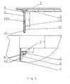
- such a holding device for an electrical / electronic installation device has at least one first holding part 1, which is present on a flush-mounted box 2, which cooperates with a second holding part 3, the rotationally heavy on the bottom 4 of an electrical / electronic installation device 5 is held.
- the first holding part 1 is formed as a detent spring made of metal, which has two elastically deflectable latching arms 6. About, for simplicity not shown in detail, locking tongues, the first holding part 1 in a holding recess 7 of an attached to the flush-mounted box 2 adapter part 8 is fixed.
- the second holding part 3 is designed as a threaded pin, which is on the one hand rotationally screwed into a present at the bottom 4 of the electrical / electronic installation device 5 bore 9. In order to create a rotationally heavy connection of the second holding part 3, the second holding part 3 is self-tapping screwed into the bore 9 with a corresponding self-locking.
- a retaining bush 10 is screwed onto the designed as a threaded pin second holding part 3, which comes directly to the first holding part 1 in operative connection.
- the retaining sleeve 10 is provided on its outer side with a locking bead 11. So that different sized tolerances X can be compensated, the Retaining bush 10 can be adjusted continuously by rotation with respect to their position on the second holding part 3 or on a threaded pin extension 13.
- the adapter part 8 is designed as a separate component and fixed on each other coming into operative engagement locking means 12 to the flush box 2.
- two adapter parts 8, two first holding parts 1 and two second holding parts 3 cooperating therewith are provided in each case.
- the flush-mounted box 2 is installed in the wall so that no need for tolerance compensation is necessary to determine the requirements of the electrical / electronic installation device 5.
- the retaining sleeve 10 is screwed onto the run as a threaded pin second holding part 3 so far that it comes with its upper end directly to the bottom 4 of the electrical / electronic installation device 5 to the plant.
- the retaining sleeve 10 is thus in its upper position. If the electrical / electronic installation device 5 is installed in the flush-mounted box 2, the retaining bush 10 comes into operative connection directly with the first holding part 1 designed as a detent spring. To achieve this, the electrical / electronic installation device 5 need only be pressed with appropriate force in the flush box 2.
- the electrical / electronic installation device 5 in a safe and secure manner in or fixed to the flush-mounted box 2 , Since the tolerance compensation and setting creating holding parts 1, 3 are assigned to the underside of the electrical / electronic installation device 5, the appearance of the defining top of the electrical / electronic installation device 5 is completely free of the overall image interfering elements.
- the flush-mounted box 2 is installed in the wall so that the need for fixing the electrical / electronic installation device 5, a slight tolerance compensation is necessary.
- the retaining sleeve 10 so far is screwed onto the executed as a threaded pin second holding part 3, so that it assumes its position in the central region of the second holding part 3.
- the retaining sleeve 10 is thus in its middle position. If the electrical / electronic installation device 5 is installed in the flush-mounted box 2, the retaining bush 10 comes into operative connection directly with the first holding part 1 designed as a detent spring. To achieve this, the electrical / electronic installation device 5 need only be pressed with appropriate force in the flush box 2.
- the electrical / electronic installation device 5 in a reliable manner positionally secure in or fixed to the flush-mounted box 2 , whereby automatically the necessary tolerance compensation takes place. Since the tolerance compensation and setting creating holding parts 1, 3 are assigned to the underside of the electrical / electronic installation device 5, the appearance of the defining top of the electrical / electronic installation device 5 is completely free of the overall image interfering elements.
- the flush-mounted box 2 is installed in the wall so that the need-based fixing of the electrical / electronic installation device 5, a large tolerance compensation is necessary.
- the necessary tolerance compensation is so great that the executed as a threaded pin second holding part 3 must be provided with a threaded pin extension 13.
- the threaded pin extension 13 is determined by a second retaining sleeve 101 on the second holding part 3. Both the free end region of the second holding part 3, as well as one of the two free end portions of the threaded pin extension 13 are each screwed to 50% in the second retaining sleeve 101.
- the retaining bush 10 is screwed on the threaded pin extension 13 so far, so that it assumes its position in the central region of the threaded pin extension 13. If the electrical / electronic installation device 5 is installed in the flush-mounted box 2, the retaining bush 10 comes into operative connection directly with the first holding part 1 designed as a detent spring. To this, too reach, needs the electrical / electronic installation device 5 only with appropriate force in the flush box 2 are pressed. Trained as a detent spring first holding part 1 finally snaps with its two elastically deflectable locking arms 6 behind the existing on the outside of the retaining sleeve 10 Rastwulst 11.
- the electrical / electronic installation device 5 in a reliable manner positionally secured in the flush-mounted box 2, automatically the necessary tolerance compensation takes place. Since the tolerance compensation and setting creating holding parts 1, 3 are assigned to the underside of the electrical / electronic installation device 5, the appearance of the defining top of the electrical / electronic installation device 5 is completely free of the overall image interfering elements.
Landscapes
- Engineering & Computer Science (AREA)
- Architecture (AREA)
- Civil Engineering (AREA)
- Structural Engineering (AREA)
- Casings For Electric Apparatus (AREA)
- Electrical Discharge Machining, Electrochemical Machining, And Combined Machining (AREA)
Priority Applications (1)
| Application Number | Priority Date | Filing Date | Title |
|---|---|---|---|
| PL07013841T PL1906501T3 (pl) | 2006-09-26 | 2007-07-14 | Urządzenie mocujące |
Applications Claiming Priority (1)
| Application Number | Priority Date | Filing Date | Title |
|---|---|---|---|
| DE102006045806A DE102006045806B3 (de) | 2006-09-26 | 2006-09-26 | Haltevorrichtung |
Publications (3)
| Publication Number | Publication Date |
|---|---|
| EP1906501A2 EP1906501A2 (de) | 2008-04-02 |
| EP1906501A3 EP1906501A3 (de) | 2010-08-04 |
| EP1906501B1 true EP1906501B1 (de) | 2011-07-13 |
Family
ID=38690507
Family Applications (1)
| Application Number | Title | Priority Date | Filing Date |
|---|---|---|---|
| EP07013841A Not-in-force EP1906501B1 (de) | 2006-09-26 | 2007-07-14 | Haltevorrichtung |
Country Status (4)
| Country | Link |
|---|---|
| EP (1) | EP1906501B1 (pl) |
| AT (1) | ATE516618T1 (pl) |
| DE (1) | DE102006045806B3 (pl) |
| PL (1) | PL1906501T3 (pl) |
Families Citing this family (4)
| Publication number | Priority date | Publication date | Assignee | Title |
|---|---|---|---|---|
| GB201208452D0 (en) * | 2012-05-11 | 2012-06-27 | Dionysiou Charles | Easybox |
| DE102014100537B4 (de) * | 2014-01-17 | 2015-10-01 | Kablo Kablo | Installationseinheit mit Dose und Geräterahmen |
| DE102014104383A1 (de) | 2014-03-28 | 2015-10-01 | Berker Gmbh & Co. Kg | Wandintegrierte Anzeigevorrichtung |
| EP4435985A1 (en) * | 2023-03-21 | 2024-09-25 | Berker GmbH & Co. KG | Apparatus of an electrical installation |
Family Cites Families (5)
| Publication number | Priority date | Publication date | Assignee | Title |
|---|---|---|---|---|
| GB325608A (en) * | 1928-12-03 | 1930-02-27 | Sydney Orient Bowker | Improved means for securing the covers of boxes and electric switches |
| GB436604A (en) * | 1934-06-04 | 1935-10-15 | Reginald Howard Baker | Improvements relating to the mounting of electric switches |
| DE29520459U1 (de) * | 1995-12-22 | 1997-04-24 | Gira Giersiepen Gmbh & Co Kg, 42477 Radevormwald | Elektrisches Installationsgerät mit Zentralabdeckung |
| DE29907456U1 (de) * | 1999-04-27 | 1999-07-29 | Gebr. Berker GmbH & Co, 58579 Schalksmühle | Adapter für elektrische Geräteunterputzdosen und Gerätehohlwanddosen |
| DE20008823U1 (de) * | 2000-05-16 | 2001-10-04 | Tehalit GmbH & Co. KG, 67716 Heltersberg | Gerätebaueinheit für Sockelleisten-Installationskanäle |
-
2006
- 2006-09-26 DE DE102006045806A patent/DE102006045806B3/de not_active Expired - Fee Related
-
2007
- 2007-07-14 EP EP07013841A patent/EP1906501B1/de not_active Not-in-force
- 2007-07-14 AT AT07013841T patent/ATE516618T1/de active
- 2007-07-14 PL PL07013841T patent/PL1906501T3/pl unknown
Also Published As
| Publication number | Publication date |
|---|---|
| ATE516618T1 (de) | 2011-07-15 |
| EP1906501A2 (de) | 2008-04-02 |
| PL1906501T3 (pl) | 2011-12-30 |
| DE102006045806B3 (de) | 2007-12-20 |
| EP1906501A3 (de) | 2010-08-04 |
Similar Documents
| Publication | Publication Date | Title |
|---|---|---|
| EP2398350B1 (de) | Eckverbindung | |
| EP1906501B1 (de) | Haltevorrichtung | |
| EP3257121B1 (de) | Anordnung mehrerer rastfüsse für eine baugruppe | |
| EP2059718B1 (de) | Anschlussvorrichtung für leuchten | |
| DE4040473C2 (pl) | ||
| DE102016213716B4 (de) | Einbaudose | |
| DE102004043651B4 (de) | Elektrische/elektronische Installationseinheit | |
| DE102009060378B3 (de) | Elektrisches Installationsgerät | |
| DE102007039065B4 (de) | Elektronisches Gerät | |
| DE202007016981U1 (de) | Befestigungsvorrichtung für ein elektrotechnisches Bauteil | |
| EP1886603A1 (de) | Einsteckvorrichtung, Einsteckgegenstand sowie Anordnung aus einer Einsteckvorrichtung und einem Einsteckgegenstand | |
| DE102011050262B3 (de) | Elektrisches Installationsgerät | |
| WO2015062972A1 (de) | Vorrichtung zum anschluss elektrischer leuchten mit fehlstromableitung | |
| DE102011101759B4 (de) | Vorrichtung zur Montage eines elektrischen Bauteils, insbesondere eines Schalters, an einer Montageplatte | |
| EP0854554B1 (de) | Installationsgerät | |
| DE20103739U1 (de) | Elektrisches Installationsgerät | |
| EP0863582A1 (de) | Abdeckung für elektrische Installationsgeräte | |
| DE102014110652B3 (de) | Elektrisches/elektronisches Installationsgerät | |
| EP3584888A1 (de) | Gerätestecker zum einschieben in eine gehäusewand sowie gerätesteckersystem und elektrogerät | |
| DE102011000069B3 (de) | Elektrische Schutzkontaktsteckdose | |
| EP3503310B1 (de) | Elektrisches/elektronisches installationsgerät | |
| EP3255966B1 (de) | Gehäuse eines elektrischen und/oder elektronischen gerätes | |
| DE102004043650B4 (de) | Elektrische/elektronische Installationseinheit | |
| DE102006060231A1 (de) | Elektrisches/elektronisches Installationsgerät | |
| DE102017111755B3 (de) | Elektrisches Installationsgerät |
Legal Events
| Date | Code | Title | Description |
|---|---|---|---|
| PUAI | Public reference made under article 153(3) epc to a published international application that has entered the european phase |
Free format text: ORIGINAL CODE: 0009012 |
|
| AK | Designated contracting states |
Kind code of ref document: A2 Designated state(s): AT BE BG CH CY CZ DE DK EE ES FI FR GB GR HU IE IS IT LI LT LU LV MC MT NL PL PT RO SE SI SK TR |
|
| AX | Request for extension of the european patent |
Extension state: AL BA HR MK YU |
|
| PUAL | Search report despatched |
Free format text: ORIGINAL CODE: 0009013 |
|
| AK | Designated contracting states |
Kind code of ref document: A3 Designated state(s): AT BE BG CH CY CZ DE DK EE ES FI FR GB GR HU IE IS IT LI LT LU LV MC MT NL PL PT RO SE SI SK TR |
|
| AX | Request for extension of the european patent |
Extension state: AL BA HR MK RS |
|
| 17P | Request for examination filed |
Effective date: 20100907 |
|
| GRAP | Despatch of communication of intention to grant a patent |
Free format text: ORIGINAL CODE: EPIDOSNIGR1 |
|
| RIC1 | Information provided on ipc code assigned before grant |
Ipc: H02G 3/18 20060101AFI20110218BHEP |
|
| AKX | Designation fees paid |
Designated state(s): AT BE BG CH CY CZ DE DK EE ES FI FR GB GR HU IE IS IT LI LT LU LV MC MT NL PL PT RO SE SI SK TR |
|
| GRAS | Grant fee paid |
Free format text: ORIGINAL CODE: EPIDOSNIGR3 |
|
| GRAA | (expected) grant |
Free format text: ORIGINAL CODE: 0009210 |
|
| AK | Designated contracting states |
Kind code of ref document: B1 Designated state(s): AT BE BG CH CY CZ DE DK EE ES FI FR GB GR HU IE IS IT LI LT LU LV MC MT NL PL PT RO SE SI SK TR |
|
| REG | Reference to a national code |
Ref country code: GB Ref legal event code: FG4D Free format text: NOT ENGLISH |
|
| REG | Reference to a national code |
Ref country code: CH Ref legal event code: EP |
|
| REG | Reference to a national code |
Ref country code: IE Ref legal event code: FG4D Free format text: LANGUAGE OF EP DOCUMENT: GERMAN |
|
| REG | Reference to a national code |
Ref country code: DE Ref legal event code: R096 Ref document number: 502007007640 Country of ref document: DE Effective date: 20110908 |
|
| REG | Reference to a national code |
Ref country code: NL Ref legal event code: VDEP Effective date: 20110713 |
|
| PG25 | Lapsed in a contracting state [announced via postgrant information from national office to epo] |
Ref country code: MT Free format text: LAPSE BECAUSE OF FAILURE TO SUBMIT A TRANSLATION OF THE DESCRIPTION OR TO PAY THE FEE WITHIN THE PRESCRIBED TIME-LIMIT Effective date: 20110713 |
|
| REG | Reference to a national code |
Ref country code: PL Ref legal event code: T3 |
|
| PG25 | Lapsed in a contracting state [announced via postgrant information from national office to epo] |
Ref country code: LT Free format text: LAPSE BECAUSE OF FAILURE TO SUBMIT A TRANSLATION OF THE DESCRIPTION OR TO PAY THE FEE WITHIN THE PRESCRIBED TIME-LIMIT Effective date: 20110713 Ref country code: FI Free format text: LAPSE BECAUSE OF FAILURE TO SUBMIT A TRANSLATION OF THE DESCRIPTION OR TO PAY THE FEE WITHIN THE PRESCRIBED TIME-LIMIT Effective date: 20110713 Ref country code: IS Free format text: LAPSE BECAUSE OF FAILURE TO SUBMIT A TRANSLATION OF THE DESCRIPTION OR TO PAY THE FEE WITHIN THE PRESCRIBED TIME-LIMIT Effective date: 20111113 Ref country code: PT Free format text: LAPSE BECAUSE OF FAILURE TO SUBMIT A TRANSLATION OF THE DESCRIPTION OR TO PAY THE FEE WITHIN THE PRESCRIBED TIME-LIMIT Effective date: 20111114 Ref country code: NL Free format text: LAPSE BECAUSE OF FAILURE TO SUBMIT A TRANSLATION OF THE DESCRIPTION OR TO PAY THE FEE WITHIN THE PRESCRIBED TIME-LIMIT Effective date: 20110713 Ref country code: SE Free format text: LAPSE BECAUSE OF FAILURE TO SUBMIT A TRANSLATION OF THE DESCRIPTION OR TO PAY THE FEE WITHIN THE PRESCRIBED TIME-LIMIT Effective date: 20110713 |
|
| REG | Reference to a national code |
Ref country code: IE Ref legal event code: FD4D |
|
| PG25 | Lapsed in a contracting state [announced via postgrant information from national office to epo] |
Ref country code: CY Free format text: LAPSE BECAUSE OF FAILURE TO SUBMIT A TRANSLATION OF THE DESCRIPTION OR TO PAY THE FEE WITHIN THE PRESCRIBED TIME-LIMIT Effective date: 20110713 Ref country code: SI Free format text: LAPSE BECAUSE OF FAILURE TO SUBMIT A TRANSLATION OF THE DESCRIPTION OR TO PAY THE FEE WITHIN THE PRESCRIBED TIME-LIMIT Effective date: 20110713 Ref country code: LV Free format text: LAPSE BECAUSE OF FAILURE TO SUBMIT A TRANSLATION OF THE DESCRIPTION OR TO PAY THE FEE WITHIN THE PRESCRIBED TIME-LIMIT Effective date: 20110713 Ref country code: MC Free format text: LAPSE BECAUSE OF NON-PAYMENT OF DUE FEES Effective date: 20110731 Ref country code: GR Free format text: LAPSE BECAUSE OF FAILURE TO SUBMIT A TRANSLATION OF THE DESCRIPTION OR TO PAY THE FEE WITHIN THE PRESCRIBED TIME-LIMIT Effective date: 20111014 |
|
| REG | Reference to a national code |
Ref country code: CH Ref legal event code: PL |
|
| PG25 | Lapsed in a contracting state [announced via postgrant information from national office to epo] |
Ref country code: SK Free format text: LAPSE BECAUSE OF FAILURE TO SUBMIT A TRANSLATION OF THE DESCRIPTION OR TO PAY THE FEE WITHIN THE PRESCRIBED TIME-LIMIT Effective date: 20110713 Ref country code: IE Free format text: LAPSE BECAUSE OF FAILURE TO SUBMIT A TRANSLATION OF THE DESCRIPTION OR TO PAY THE FEE WITHIN THE PRESCRIBED TIME-LIMIT Effective date: 20110713 Ref country code: CH Free format text: LAPSE BECAUSE OF NON-PAYMENT OF DUE FEES Effective date: 20110731 Ref country code: LI Free format text: LAPSE BECAUSE OF NON-PAYMENT OF DUE FEES Effective date: 20110731 Ref country code: CZ Free format text: LAPSE BECAUSE OF FAILURE TO SUBMIT A TRANSLATION OF THE DESCRIPTION OR TO PAY THE FEE WITHIN THE PRESCRIBED TIME-LIMIT Effective date: 20110713 |
|
| PLBE | No opposition filed within time limit |
Free format text: ORIGINAL CODE: 0009261 |
|
| STAA | Information on the status of an ep patent application or granted ep patent |
Free format text: STATUS: NO OPPOSITION FILED WITHIN TIME LIMIT |
|
| PG25 | Lapsed in a contracting state [announced via postgrant information from national office to epo] |
Ref country code: RO Free format text: LAPSE BECAUSE OF FAILURE TO SUBMIT A TRANSLATION OF THE DESCRIPTION OR TO PAY THE FEE WITHIN THE PRESCRIBED TIME-LIMIT Effective date: 20110713 Ref country code: IT Free format text: LAPSE BECAUSE OF FAILURE TO SUBMIT A TRANSLATION OF THE DESCRIPTION OR TO PAY THE FEE WITHIN THE PRESCRIBED TIME-LIMIT Effective date: 20110713 Ref country code: EE Free format text: LAPSE BECAUSE OF FAILURE TO SUBMIT A TRANSLATION OF THE DESCRIPTION OR TO PAY THE FEE WITHIN THE PRESCRIBED TIME-LIMIT Effective date: 20110713 |
|
| 26N | No opposition filed |
Effective date: 20120416 |
|
| PG25 | Lapsed in a contracting state [announced via postgrant information from national office to epo] |
Ref country code: DK Free format text: LAPSE BECAUSE OF FAILURE TO SUBMIT A TRANSLATION OF THE DESCRIPTION OR TO PAY THE FEE WITHIN THE PRESCRIBED TIME-LIMIT Effective date: 20110713 |
|
| REG | Reference to a national code |
Ref country code: DE Ref legal event code: R097 Ref document number: 502007007640 Country of ref document: DE Effective date: 20120416 |
|
| PG25 | Lapsed in a contracting state [announced via postgrant information from national office to epo] |
Ref country code: ES Free format text: LAPSE BECAUSE OF FAILURE TO SUBMIT A TRANSLATION OF THE DESCRIPTION OR TO PAY THE FEE WITHIN THE PRESCRIBED TIME-LIMIT Effective date: 20111024 |
|
| PG25 | Lapsed in a contracting state [announced via postgrant information from national office to epo] |
Ref country code: LU Free format text: LAPSE BECAUSE OF NON-PAYMENT OF DUE FEES Effective date: 20110714 |
|
| PG25 | Lapsed in a contracting state [announced via postgrant information from national office to epo] |
Ref country code: BG Free format text: LAPSE BECAUSE OF FAILURE TO SUBMIT A TRANSLATION OF THE DESCRIPTION OR TO PAY THE FEE WITHIN THE PRESCRIBED TIME-LIMIT Effective date: 20111013 |
|
| PG25 | Lapsed in a contracting state [announced via postgrant information from national office to epo] |
Ref country code: TR Free format text: LAPSE BECAUSE OF FAILURE TO SUBMIT A TRANSLATION OF THE DESCRIPTION OR TO PAY THE FEE WITHIN THE PRESCRIBED TIME-LIMIT Effective date: 20110713 |
|
| PG25 | Lapsed in a contracting state [announced via postgrant information from national office to epo] |
Ref country code: HU Free format text: LAPSE BECAUSE OF FAILURE TO SUBMIT A TRANSLATION OF THE DESCRIPTION OR TO PAY THE FEE WITHIN THE PRESCRIBED TIME-LIMIT Effective date: 20110713 |
|
| REG | Reference to a national code |
Ref country code: FR Ref legal event code: PLFP Year of fee payment: 10 |
|
| REG | Reference to a national code |
Ref country code: FR Ref legal event code: PLFP Year of fee payment: 11 |
|
| REG | Reference to a national code |
Ref country code: FR Ref legal event code: PLFP Year of fee payment: 12 |
|
| PGFP | Annual fee paid to national office [announced via postgrant information from national office to epo] |
Ref country code: PL Payment date: 20210621 Year of fee payment: 15 |
|
| PGFP | Annual fee paid to national office [announced via postgrant information from national office to epo] |
Ref country code: AT Payment date: 20210621 Year of fee payment: 15 Ref country code: FR Payment date: 20210726 Year of fee payment: 15 |
|
| PGFP | Annual fee paid to national office [announced via postgrant information from national office to epo] |
Ref country code: GB Payment date: 20210727 Year of fee payment: 15 Ref country code: BE Payment date: 20210727 Year of fee payment: 15 Ref country code: DE Payment date: 20210728 Year of fee payment: 15 |
|
| REG | Reference to a national code |
Ref country code: DE Ref legal event code: R119 Ref document number: 502007007640 Country of ref document: DE |
|
| REG | Reference to a national code |
Ref country code: AT Ref legal event code: MM01 Ref document number: 516618 Country of ref document: AT Kind code of ref document: T Effective date: 20220714 |
|
| GBPC | Gb: european patent ceased through non-payment of renewal fee |
Effective date: 20220714 |
|
| REG | Reference to a national code |
Ref country code: BE Ref legal event code: MM Effective date: 20220731 |
|
| PG25 | Lapsed in a contracting state [announced via postgrant information from national office to epo] |
Ref country code: FR Free format text: LAPSE BECAUSE OF NON-PAYMENT OF DUE FEES Effective date: 20220731 Ref country code: AT Free format text: LAPSE BECAUSE OF NON-PAYMENT OF DUE FEES Effective date: 20220714 |
|
| PG25 | Lapsed in a contracting state [announced via postgrant information from national office to epo] |
Ref country code: GB Free format text: LAPSE BECAUSE OF NON-PAYMENT OF DUE FEES Effective date: 20220714 Ref country code: DE Free format text: LAPSE BECAUSE OF NON-PAYMENT OF DUE FEES Effective date: 20230201 Ref country code: BE Free format text: LAPSE BECAUSE OF NON-PAYMENT OF DUE FEES Effective date: 20220731 |
|
| PG25 | Lapsed in a contracting state [announced via postgrant information from national office to epo] |
Ref country code: PL Free format text: LAPSE BECAUSE OF NON-PAYMENT OF DUE FEES Effective date: 20220714 |