EP1906193A1 - Method and device for detecting charged state of battery - Google Patents
Method and device for detecting charged state of battery Download PDFInfo
- Publication number
- EP1906193A1 EP1906193A1 EP06757391A EP06757391A EP1906193A1 EP 1906193 A1 EP1906193 A1 EP 1906193A1 EP 06757391 A EP06757391 A EP 06757391A EP 06757391 A EP06757391 A EP 06757391A EP 1906193 A1 EP1906193 A1 EP 1906193A1
- Authority
- EP
- European Patent Office
- Prior art keywords
- state
- battery
- charge
- internal impedance
- stable
- Prior art date
- Legal status (The legal status is an assumption and is not a legal conclusion. Google has not performed a legal analysis and makes no representation as to the accuracy of the status listed.)
- Granted
Links
Images


Classifications
-
- G—PHYSICS
- G01—MEASURING; TESTING
- G01R—MEASURING ELECTRIC VARIABLES; MEASURING MAGNETIC VARIABLES
- G01R31/00—Arrangements for testing electric properties; Arrangements for locating electric faults; Arrangements for electrical testing characterised by what is being tested not provided for elsewhere
- G01R31/36—Arrangements for testing, measuring or monitoring the electrical condition of accumulators or electric batteries, e.g. capacity or state of charge [SoC]
- G01R31/367—Software therefor, e.g. for battery testing using modelling or look-up tables
-
- G—PHYSICS
- G01—MEASURING; TESTING
- G01R—MEASURING ELECTRIC VARIABLES; MEASURING MAGNETIC VARIABLES
- G01R31/00—Arrangements for testing electric properties; Arrangements for locating electric faults; Arrangements for electrical testing characterised by what is being tested not provided for elsewhere
- G01R31/36—Arrangements for testing, measuring or monitoring the electrical condition of accumulators or electric batteries, e.g. capacity or state of charge [SoC]
- G01R31/374—Arrangements for testing, measuring or monitoring the electrical condition of accumulators or electric batteries, e.g. capacity or state of charge [SoC] with means for correcting the measurement for temperature or ageing
-
- G—PHYSICS
- G01—MEASURING; TESTING
- G01R—MEASURING ELECTRIC VARIABLES; MEASURING MAGNETIC VARIABLES
- G01R31/00—Arrangements for testing electric properties; Arrangements for locating electric faults; Arrangements for electrical testing characterised by what is being tested not provided for elsewhere
- G01R31/36—Arrangements for testing, measuring or monitoring the electrical condition of accumulators or electric batteries, e.g. capacity or state of charge [SoC]
- G01R31/389—Measuring internal impedance, internal conductance or related variables
Definitions
- Patent document 1 discloses the proportionality relation between OCV and SOC, and measurement of OCV enables detection of an SOC.
- Patent document 1 Japanese Laid-open patent publication No. 2004-530880
- the calculated battery remaining amount is sometimes smaller than the actual battery remaining amount, this may cause such a problem that an optical output can not be obtained from a battery used in a vehicle power supply system when necessary.
- a first aspect of the method for detecting a state of charge of a battery of the present invention is a method including the steps of: measuring an internal impedance of the battery; measuring a stable-state voltage of the battery; compensatively correcting the stable-state voltage in accordance with the internal impedance; and obtaining the state of charge of the battery based on a corrected stable-state voltage.
- a second aspect of the method for detecting a state of charge of a battery of the present invention is a method in which the step of obtaining the state of charge is performed by substituting the corrected stable-state voltage into a function showing a relation between the stable-state voltage and the state of charge.
- a third aspect of the method for detecting a state of charge of a battery of the present invention is a method including the steps of: measuring an internal impedance of the battery; measuring a stable-state voltage of the battery; and obtaining the state of charge of the battery by substituting the corrected stable-state voltage into a function showing a relation between the stable-state voltage and the state of charge.
- a fourth aspect of the method for detecting a state of charge of a battery of the present invention is a method in which at least one of a coefficient and a constant of the function showing the relation between the stable-state voltage and the state of charge is corrected in accordance with the internal impedance.
- a fifth aspect of the method for detecting a state of charge of a battery of the present invention is a method in which the function is a linear function.
- a seventh aspect of the method for detecting a state of charge of a battery of the present invention is a method including: the steps of: measuring an internal impedance of the battery; measuring a stable-state voltage of the battery; preparing matrix data showing relations between internal impedances and stable-state voltages respectively associated with plurally divided ranges of the state of charge; and obtaining the state of charge corresponding to one of the ranges which includes the internal impedance and the stable-state voltage.
- An eighth aspect of the method for detecting a state of charge of a battery of the present invention is a method further including: after the step of measuring the internal impedance, the step of measuring a temperature at a time when the internal impedance is measured, and the internal impedance used in the step of obtaining the state of charge being an internal impedance of a predetermined temperature corrected based on a previously obtained relation between the internal impedance and the temperature.
- a ninth aspect of the method for detecting a state of charge of a battery of the present invention is a method further including: after the step of measuring the internal impedance, the step of measuring a temperature at a time when the internal impedance is measured; after the step of obtaining the state of charge, the step of correcting the internal impedance to a corrected internal impedance of a predetermined temperature corrected based on a previously obtained relation between the internal impedance and the temperature; and obtaining the state of charge corresponding to one of the ranges which includes the corrected internal impedance and the stable-state voltage.
- a first aspect of the battery state-of-charge detecting apparatus of the present invention is a battery state-of-charge detecting apparatus having: internal impedance measuring unit for measuring an internal impedance of a battery; voltage measuring unit for measuring a stable-state voltage of the battery; stable-state voltage correcting unit for correcting the stable-state voltage in accordance with the internal impedance measured by the internal impedance measuring unit; and state-of-charge calculating unit for obtaining a state of charge of the battery based on a corrected stable-state voltage corrected by the stable-state voltage correcting unit.
- a second aspect of the battery state-of-charge detecting apparatus of the present invention is a battery state-of-charge detecting apparatus in which the state-of-charge calculating unit obtains the state of charge by substituting the internal impedance measured by the internal impedance measuring unit into a function showing a relation between the stable-state voltage and the state of charge.
- a third aspect of the battery state-of-charge detecting apparatus of the present invention is a battery state-of-charge detecting apparatus having: internal impedance measuring unit for measuring an internal impedance of a battery; voltage measuring unit for measuring a stable-state voltage of the battery; and state-of-charge calculating unit for obtaining a state of charge of the battery by substituting the internal impedance measured by the internal impedance measuring unit into a function showing a relation between the stable-state voltage and the state of charge.
- a fourth aspect of the battery state-of-charge detecting apparatus of the present invention is a battery state-of-charge detecting apparatus in which at least one of a coefficient and a constant of the function showing the relation between the stable-state voltage and the state of charge is corrected in accordance with the internal impedance measured by the internal impedance measuring unit.
- a fifth aspect of the battery state-of-charge detecting apparatus of the present invention is a battery state-of-charge detecting apparatus in which the function is a linear function.
- a seventh aspect of the battery state-of-charge detecting apparatus of the present invention is a battery state-of-charge detecting apparatus having: internal impedance measuring unit for measuring an internal impedance of a battery; voltage measuring unit for measuring a stable-state voltage of the battery; data memory for storing matrix data showing relations between internal impedances and stable-state voltages as respectively associated with plurally divided ranges of the state of charge; and state-of-charge calculating unit for calculating out a state of charge by obtaining one of the ranges that corresponds to matrix data including the internal impedance measured by the internal impedance measuring unit and the stable-state voltage measured by the voltage measuring unit.
- An eighth aspect of the battery state-of-charge detecting apparatus of the present invention is a battery state-of-charge detecting apparatus in which the internal impedance measuring unit corrects the internal impedance measured by the internal impedance measuring unit, based on a temperature of the battery, to output a corrected internal impedance of a predetermined temperature.
- a ninth aspect of the battery state-of-charge detecting apparatus of the present invention is a battery state-of-charge detecting apparatus in which the internal impedance measuring unit corrects the corrected internal impedance of the predetermined temperature based on the state of charge calculated by the state-of-charge calculating unit to output a further corrected internal impedance.
- a tenth aspect of the battery state-of-charge detecting apparatus of the present invention is a battery state-of-charge detecting apparatus further including a temperature sensor attached to the battery for detecting the temperature of the battery to output temperature data to the internal impedance measuring unit.
- a battery state of charge is detected by measuring an internal impedance and a battery stable-state voltage, correcting upward the battery stable-state voltage based on the internal impedance and calculating the state of charge based on the corrected voltage .
- the internal impedance increased with the battery deteriorating is measured, it is possible to detect the battery state of charge precisely in accordance with deterioration of the battery.
- data of the relation between internal impedance and stable-state voltage of a battery is stored as matrix data and the matrix data is associated with corresponding one of plurally divided ranges of the state of charge. Then it is determined to which range of the battery state of charge a measured internal impedance and a measured battery stable-state voltage correspond, and a level defined for the determined range is detected as a state of charge level. This enables precise detection of a current level of the battery state of charge based on the internal impedance which varies as the battery deteriorates.
- the temperature of the battery and the internal impedance are first measured, and the measured internal impedance is corrected to an internal impedance of a predetermined temperature.
- the battery state of charge is first detected, the internal impedance is corrected by the detected state of charge and the corrected internal impedance is used to obtain a battery state of charge, thereby enabling more precise detection of the battery state of charge.
- Fig. 1 is a view illustrating a battery state-of-charge detecting apparatus according the first embodiment of the present invention.
- a battery 1 is connected to a discharge circuit 3 for controlling a current supplied from the battery 1 to a load 2, a charge circuit 4 for charging power supply and a battery SOC detecting portion 10 for measuring a open-circuit state of charge.
- the battery SOC detecting portion 10 includes internal impedance measuring unit 11 connected to positive and negative terminals of the battery 1 for measuring an internal impedance of the battery 1, OCV measuring unit 12 connected to both of the terminals of the battery 1 for measuring an OCV (Open Circuit Voltage), OCV correcting unit 13 for correcting the OCV output from the OCV measuring unit 12 based on the internal impedance output from the internal impedance measuring unit 11 to output a corrected OCV and SOC calculating unit 16 receiving the corrected OCV output from the OCV correcting unit to determine an SOC (State of Charge) of the battery 1.
- the OCV is also referred to as stable-state voltage.
- the OCV calculating unit 16 is configured to calculate an SOC by substituting the corrected OCV, which is output from the OCV correcting unit 13, into the function of SOC-OCV characteristic of the battery 1 in new conditions (also referred to as "new battery"), and to output a calculation result to a processing device 6 such as a display unit.
- the SOC is expressed, for example, as 100 % when the battery is fully charged.
- the SOC-OCV relation of the new battery 1 is expressed by the linear function such as shown in Fig. 2 .
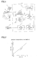
- the battery 1 has properties such that the internal impedance is increased as the battery 1 is deteriorating and the increase of the internal impedance causes reduction of battery voltage during discharge, as illustrated in Fig. 4 .
- the relation between internal impedance and OCV of the battery 1 is as shown in Fig. 5 when the SOC is a parameter.
- SOC a parameter
- an OCV V 1 of the deteriorated battery 1 is lower than an OCV V 0 of the new battery 1
- an internal impedance R 1 of the deteriorated battery 1 is larger than an internal impedance R 0 of the new battery 1.
- the SOC of the deteriorated battery 1 is calculated by substituting the measured OCV as it is into the function shown in Fig. 2 , the calculated SOC is different from an actual SOC.
- the relation between internal impedance and OCV and the measured internal impedance R 1 are used to correct the actual measured OCV V 1 of the deteriorated battery 1 upward to the OCV V 0 of the new battery 1, and then, the corrected value V 0 is substituted into the function shown in Fig. 2 . This makes it possible to enhance detection accuracy of the SOC.
- the battery 1 targeted for SOC detection is connected to the battery state-of-charge detecting portion 10, and an internal impedance R 1 and an OCV V 1 measured by the internal impedance measuring unit 11 and the OCV measuring unit 12, respectively, are input to the OCV correcting unit 13 (Steps 1 and 2 in Fig. 6 ).
- the OCV correcting unit 13 obtains from the data of the correction data memory 14, for example, data of the relation shown in Fig. 5 , a value V 0 of the new battery obtained when the SOC is N% corresponding to the intersection between the values R 1 and V 1 , and corrects the actual value V 1 upward to the value V 0 (Step 3 in Fig. 6 ).
- correction of the OCV is not limited to this method, and for example, the actual internal impedance and the actual OCV of the battery 1 may be used as a basis to correct the actual OCV into the OCV of the new battery.
- the thus-corrected OCV is output from the OCV correcting unit 13 to the SOC calculating unit 16.
- the SOC calculating unit 16 substitutes the corrected OCV into the linear function such as shown in Fig. 2 to calculate an SOC as N% (Step 4 in Fig 6 ), and outputs the calculated SOC to the SOC outputting unit 17.
- the calculated SOC N% is output from the SOC outputting unit 17 to the processing device 6.
- Fig. 7 is a view illustrating a battery state-of-charge detecting apparatus according the second embodiment of the present invention.
- a battery state-of-charge detecting portion 20 has: internal impedance measuring unit 11 connected to the both terminals of the battery 1 for measuring an internal impedance of the battery 1 to output the measured data; OCV measuring unit 12 for measuring an open circuit voltage (OCV) between both terminals of the battery 1 to output the measured data; an SOC-OCV characteristic memory 26 for storing a program for calculation based on the function of the SOC-OCV characteristic of the battery 1; SOC calculating unit 27 for capturing the program from the SOC-OCV characteristic memory 26 and running the program with use of the measured OCV received from the OCV measuring unit 12 to calculate an SOC; and SOC outputting unit 17 for outputting the calculated SOC, output from the SOC calculating unit 27, to a processing device 6 such as display unit
- the internal impedance measuring unit 11 has an output terminal connected to internal impedance correcting unit 21 for correcting an actual measured internal impedance of the battery 1 having temperature dependence shown in Fig. 11 to an internal impedance of a predetermined temperature.
- the internal impedance correcting unit 21 receives a temperature measured by a temperature sensor 5 attached to the battery 1 and the actual measured internal impedance measured by the internal impedance measuring unit 11, and corrects the actual measured internal impedance R 11 at the actual measured temperature T 1 of the battery 1 into an internal impedance R 01 of a predetermined temperature T 0 by use of the relation shown in Fig. 8 to output the corrected value to coefficient setting unit 25.
- the temperature used as a predetermined temperature T 0 is for example, a room temperature, an ambient temperature, or a lower or higher predetermined temperature.
- the coefficient setting unit 25 Connected to between the internal impedance correcting unit 21 and the SOC-OCV characteristic memory 26 is the coefficient setting unit 25 for setting a coefficient and a constant of the function stored in the SOC-OCV characteristic memory 26.
- the coefficient setting unit 25 changes the gradient a and the intercept b in accordance with the internal impedance output from the internal impedance correcting unit 21.
- the gradient a and the intercept b are changed for the reason described below.
- the SCO-OCV characteristic of the new battery is expressed by the broken line in Fig. 9 .
- the SOC-OCV relation is changed with deterioration of the battery 1, that is, changes in internal impedance.
- the relation between OCV and internal impedance of the battery 1 obtained by actual measurement for each SOC of 100%, 90%, 70% and 50% is such as shown in Fig. 10 , which shows that even if the SOC is the same, the OCV becomes lower with increasing internal impedance.
- the internal impedance in Fig. 10 is a corrected value of a predetermined temperature.
- the coefficient and constant of the SOC-OCV characteristic are changed with changes in the internal impedance of the battery 1, thereby to make the SOC value obtained by the function conform to the actual-measurement SOC.
- the real measured internal impedance x' is 110 mQ
- y indicative of the SOC is about 100%, which conform to the result shown in Fig. 10 .
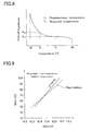
- the gradient and intercept of the function of the SOC-OCV characteristic is determined based on the actual measured internal impedance and the SOC calculated by the function and the actual measured SOC are compared, which result is shown in Fig. 13 .
- the calculated SOC and the actual measured SOC are found to be almost in good agreement. This shows that the SOC can be calculated with high accuracy based on the actual measured internal impedance and OCV.
- the coefficient and constant of the linear function of the SOC-OCV characteristic is not limited to those expressed by linear functions such as shown in Fig. 11 or may be expressed by another functions.
- the internal impedance correcting unit 21 may be configured to not only change the internal impedance to that of the predetermined temperature but also change and correct the internal impedance further based on the SOC calculated by the SOC calculating unit 27.
- the internal impedance measured by the internal impedance measuring unit 11 is changed to an internal impedance R' of the predetermined temperature by the internal impedance correcting unit 21 and the internal impedance R' is further corrected to R" based on the SOC N 1 .
- This enables more precise detection of the SOC.
- correction of the internal impedance based on the temperature and correction of the internal impedance based on both of the temperature and the SOC can be adopted in the first and third embodiments.
- Fig. 17 is a view illustrating a battery state-of-charge detecting apparatus according to the third embodiment of the present invention, and the same reference numerals as in Fig. 1 denote the same elements.
- the data stored in the above-mentioned data memory 31 is, for example, matrix data shown in Fig. 18 .
- SOC values of the battery 1 are divided into three ranges of low range, middle range and high range, for example, a range of 40% or more to less than 60%, a range of 60% or more to less than 80% and a range of 80% to 100 inclusive.
- a large amount of data of actual measured internal impedances and actual measured OCVs is collected for each of the ranges of the battery 1 of from its new state to its deteriorated state and stored as matrix data per range.
- the internal impedance measuring unit 11 and the OCV measuring unit 12 measure an internal impedance and an OCV of the battery 1, respectively, and output the measured values to the SOC level calculating unit 32 (Steps 1 and 2 in Fig. 19 ).
- the SOC level calculating unit 32 checks the measured internal impedance and OCV against matrix data in the data memory 31.
- the SOC level calculating unit 32 calculates out the SOC as a high value Q H .
- the SOC level calculating unit 32 calculates out the SOC as a middle value Q M .
- the SOC level calculating unit 32 calculates out the SOC as a low value Q L . Then, the calculated value is output to the SOC level outputting unit 33 (Step 3 in Fig. 19 ) .
Abstract
Description
- The present invention relates to a method for detecting a battery state of charge and a battery state-of-charge detecting apparatus. More particularly, the present invention relates to a method and an apparatus for detecting a battery state of charge based on a measured open circuit voltage.
- There has been known a method for detecting a battery state of charge (SOC), including measuring an open circuit voltage (OCV) of a battery in a stable state and substituting the measured value into a relational expression of OCV and SOC to calculate an SOC.
- For example, the following
patent document 1 discloses the proportionality relation between OCV and SOC, and measurement of OCV enables detection of an SOC.
Patent document 1:Japanese Laid-open patent publication No. 2004-530880 - However, the SOC-OCV relation of a battery varies as the battery is deteriorating. As time duration of use of the battery is longer, the error between an actual SOC and an SOC obtained by the relational expression of OCV and SOC becomes larger.
- When such a detection error is caused, the calculated battery remaining amount is sometimes smaller than the actual battery remaining amount, this may cause such a problem that an optical output can not be obtained from a battery used in a vehicle power supply system when necessary.
- Therefore, the present invention has an object to provide a method and an apparatus for detecting a battery state of charge precisely regardless of the deterioration state of a battery.
- A first aspect of the method for detecting a state of charge of a battery of the present invention is a method including the steps of: measuring an internal impedance of the battery; measuring a stable-state voltage of the battery; compensatively correcting the stable-state voltage in accordance with the internal impedance; and obtaining the state of charge of the battery based on a corrected stable-state voltage.
- A second aspect of the method for detecting a state of charge of a battery of the present invention is a method in which the step of obtaining the state of charge is performed by substituting the corrected stable-state voltage into a function showing a relation between the stable-state voltage and the state of charge.
- A third aspect of the method for detecting a state of charge of a battery of the present invention is a method including the steps of: measuring an internal impedance of the battery; measuring a stable-state voltage of the battery; and obtaining the state of charge of the battery by substituting the corrected stable-state voltage into a function showing a relation between the stable-state voltage and the state of charge.
- A fourth aspect of the method for detecting a state of charge of a battery of the present invention is a method in which at least one of a coefficient and a constant of the function showing the relation between the stable-state voltage and the state of charge is corrected in accordance with the internal impedance.
- A fifth aspect of the method for detecting a state of charge of a battery of the present invention is a method in which the function is a linear function.
- A sixth aspect of the method for detecting a state of charge of a battery of the present invention is a method in which, assuming the state of charge is y and the stable-state voltage is x, the linear function is expressed by y = ax + b (where a is the coefficient and b is the constant).
- A seventh aspect of the method for detecting a state of charge of a battery of the present invention is a method including: the steps of: measuring an internal impedance of the battery; measuring a stable-state voltage of the battery; preparing matrix data showing relations between internal impedances and stable-state voltages respectively associated with plurally divided ranges of the state of charge; and obtaining the state of charge corresponding to one of the ranges which includes the internal impedance and the stable-state voltage.
- An eighth aspect of the method for detecting a state of charge of a battery of the present invention is a method further including: after the step of measuring the internal impedance, the step of measuring a temperature at a time when the internal impedance is measured, and the internal impedance used in the step of obtaining the state of charge being an internal impedance of a predetermined temperature corrected based on a previously obtained relation between the internal impedance and the temperature.
- A ninth aspect of the method for detecting a state of charge of a battery of the present invention is a method further including: after the step of measuring the internal impedance, the step of measuring a temperature at a time when the internal impedance is measured; after the step of obtaining the state of charge, the step of correcting the internal impedance to a corrected internal impedance of a predetermined temperature corrected based on a previously obtained relation between the internal impedance and the temperature; and obtaining the state of charge corresponding to one of the ranges which includes the corrected internal impedance and the stable-state voltage.
- A first aspect of the battery state-of-charge detecting apparatus of the present invention is a battery state-of-charge detecting apparatus having: internal impedance measuring unit for measuring an internal impedance of a battery; voltage measuring unit for measuring a stable-state voltage of the battery; stable-state voltage correcting unit for correcting the stable-state voltage in accordance with the internal impedance measured by the internal impedance measuring unit; and state-of-charge calculating unit for obtaining a state of charge of the battery based on a corrected stable-state voltage corrected by the stable-state voltage correcting unit.
- A second aspect of the battery state-of-charge detecting apparatus of the present invention is a battery state-of-charge detecting apparatus in which the state-of-charge calculating unit obtains the state of charge by substituting the internal impedance measured by the internal impedance measuring unit into a function showing a relation between the stable-state voltage and the state of charge.
- A third aspect of the battery state-of-charge detecting apparatus of the present invention is a battery state-of-charge detecting apparatus having: internal impedance measuring unit for measuring an internal impedance of a battery; voltage measuring unit for measuring a stable-state voltage of the battery; and state-of-charge calculating unit for obtaining a state of charge of the battery by substituting the internal impedance measured by the internal impedance measuring unit into a function showing a relation between the stable-state voltage and the state of charge.
- A fourth aspect of the battery state-of-charge detecting apparatus of the present invention is a battery state-of-charge detecting apparatus in which at least one of a coefficient and a constant of the function showing the relation between the stable-state voltage and the state of charge is corrected in accordance with the internal impedance measured by the internal impedance measuring unit.
- A fifth aspect of the battery state-of-charge detecting apparatus of the present invention is a battery state-of-charge detecting apparatus in which the function is a linear function.
- A sixth aspect of the battery state-of-charge detecting apparatus of the present invention is a battery state-of-charge detecting apparatus in which, assuming the state of charge is y and the stable-state voltage is x, the linear function is expressed by y = ax + b (where a is the coefficient and b is the constant).
- A seventh aspect of the battery state-of-charge detecting apparatus of the present invention is a battery state-of-charge detecting apparatus having: internal impedance measuring unit for measuring an internal impedance of a battery; voltage measuring unit for measuring a stable-state voltage of the battery; data memory for storing matrix data showing relations between internal impedances and stable-state voltages as respectively associated with plurally divided ranges of the state of charge; and state-of-charge calculating unit for calculating out a state of charge by obtaining one of the ranges that corresponds to matrix data including the internal impedance measured by the internal impedance measuring unit and the stable-state voltage measured by the voltage measuring unit.
- An eighth aspect of the battery state-of-charge detecting apparatus of the present invention is a battery state-of-charge detecting apparatus in which the internal impedance measuring unit corrects the internal impedance measured by the internal impedance measuring unit, based on a temperature of the battery, to output a corrected internal impedance of a predetermined temperature.
- A ninth aspect of the battery state-of-charge detecting apparatus of the present invention is a battery state-of-charge detecting apparatus in which the internal impedance measuring unit corrects the corrected internal impedance of the predetermined temperature based on the state of charge calculated by the state-of-charge calculating unit to output a further corrected internal impedance.
- A tenth aspect of the battery state-of-charge detecting apparatus of the present invention is a battery state-of-charge detecting apparatus further including a temperature sensor attached to the battery for detecting the temperature of the battery to output temperature data to the internal impedance measuring unit.
- According to the present invention, a battery state of charge is detected by measuring an internal impedance and a battery stable-state voltage, correcting upward the battery stable-state voltage based on the internal impedance and calculating the state of charge based on the corrected voltage . As the internal impedance increased with the battery deteriorating is measured, it is possible to detect the battery state of charge precisely in accordance with deterioration of the battery.
- In addition, according to the present invention, data of the relation between internal impedance and stable-state voltage of a battery is stored as matrix data and the matrix data is associated with corresponding one of plurally divided ranges of the state of charge. Then it is determined to which range of the battery state of charge a measured internal impedance and a measured battery stable-state voltage correspond, and a level defined for the determined range is detected as a state of charge level. This enables precise detection of a current level of the battery state of charge based on the internal impedance which varies as the battery deteriorates.
- Furthermore, as the internal impedance varies by temperature of a battery, the temperature of the battery and the internal impedance are first measured, and the measured internal impedance is corrected to an internal impedance of a predetermined temperature. With this structure, it is possible to detect a state of charge more precisely.
- As the internal impedance varies also by a state of charge of the battery, the battery state of charge is first detected, the internal impedance is corrected by the detected state of charge and the corrected internal impedance is used to obtain a battery state of charge, thereby enabling more precise detection of the battery state of charge.
-
-
Fig. 1 is a view illustrating a configuration of a battery state-of-charge detecting apparatus according to a first embodiment of the present invention; -
Fig. 2 is a graph showing the relation between state of charge and open circuit voltage of a battery targeted for detection by the battery state-of-charge detecting apparatus according to the first embodiment of the present invention; -
Fig. 3 is a graph showing an error between an actual measured state of charge and a state of charge obtained by calculation of the battery targeted for detection by the battery state-of-charge detecting apparatus according to the first embodiment of the present invention; -
Fig. 4 is a graph showing the relation between corrected internal impedance of a predetermined temperature and battery voltage during discharge of the battery targeted for detection by the battery state-of-charge detecting apparatus according to the first embodiment of the present invention; -
Fig. 5 is a graph showing the relation between internal impedance and open circuit voltage of the battery targeted for detection by the battery state-of-charge detecting apparatus according to the first embodiment of the present invention; -
Fig. 6 is a flowchart of a method for detecting a battery state of charge according to the first embodiment of the present invention; -
Fig. 7 is a view illustrating a configuration of a battery state-of-charge detecting apparatus according to a second embodiment of the present invention; -
Fig. 8 is a graph showing the relation between temperature and internal impedance of the battery; -
Fig. 9 is a graph showing an example of the relation between open circuit voltage and a state of charge of the battery; -
Fig. 10 is a graph showing the relation between internal impedance at a predetermined temperature and open circuit voltage of the battery targeted for detection by the battery state-of-charge detecting apparatus according to the second embodiment of the present invention, in which the state of charge is shown as a parameter; -
Fig. 11 is a graph showing the internal-impedance dependence of the gradient and the intercept of the linear function of the SOC-OCV relation of the battery targeted for detection by the battery state-of-charge detecting apparatus according to the second embodiment of the present invention; -
Fig. 12 is a graph showing the linear function of the SOC-OCV relation set with use of the graph ofFig. 11 in the battery state-of-charge detecting apparatus according to the second embodiment of the present invention; -
Fig. 13 is a graph showing an error between an actual measured state of charge and a state of charge obtained by calculation of the battery targeted for detection by the battery state-of-charge detecting apparatus according to the second embodiment of the present invention; -
Fig. 14 is a flowchart of a method for detecting a battery state of charge according to the second embodiment of the present invention; -
Fig. 15 is a graph showing the relation between internal impedance and temperature targeted for detection by the battery state-of-charge detecting apparatus or the method for detecting a battery state of charge according to the embodiment of the present invention; -
Fig. 16 is a graph showing the relation between internal impedance and state of charge targeted for detection by the battery state-of-charge detecting apparatus or the method for detecting a battery state of charge according to the embodiment of the present invention; -
Fig. 17 is a view illustrating a configuration of a battery state-of-charge detecting apparatus according to a third embodiment of the present invention; -
Fig. 18 is a graph showing the relation between internal impedance and open circuit voltage of the battery targeted for detection by the battery state-of-charge detecting apparatus according to the third embodiment of the present invention, the graph showing the state of charge is divided into plural ranges and each of the ranges includes matrix data of internal impedances and open circuit voltages; and -
Fig. 19 is a flowchart of a method for detecting a battery state of charge according to the third embodiment of the present invention, showing a method for detecting an SOC with use of the graph ofFig. 18 . -
- 1
- battery
- 2
- load
- 10
- battery state-of-charge (SOC) detecting portion
- 11
- internal impedance measuring unit
- 12
- OCV measuring unit
- 13
- OCV correcting unit
- 14
- correction data memory
- 16
- SOC calculating unit
- 17
- SOC outputting unit
- 21
- internal impedance correcting unit
- 25
- coefficient setting unit
- 26
- SOC-OCV characteristic memory
- 31
- data memory
- 32
- SOC level calculating unit
- 33
- SOC level outputting unit
- Based on the drawings, embodiments of the present invention will be described in detail below.
-
Fig. 1 is a view illustrating a battery state-of-charge detecting apparatus according the first embodiment of the present invention. InFig. 1 , abattery 1 is connected to adischarge circuit 3 for controlling a current supplied from thebattery 1 to aload 2, acharge circuit 4 for charging power supply and a batterySOC detecting portion 10 for measuring a open-circuit state of charge. - The battery
SOC detecting portion 10 includes internal impedance measuring unit 11 connected to positive and negative terminals of thebattery 1 for measuring an internal impedance of thebattery 1,OCV measuring unit 12 connected to both of the terminals of thebattery 1 for measuring an OCV (Open Circuit Voltage),OCV correcting unit 13 for correcting the OCV output from theOCV measuring unit 12 based on the internal impedance output from the internal impedance measuring unit 11 to output a corrected OCV and SOC calculating unit 16 receiving the corrected OCV output from the OCV correcting unit to determine an SOC (State of Charge) of thebattery 1. Here, the OCV is also referred to as stable-state voltage. - The
OCV correcting unit 13 is configured to capture correction data stored in acorrection data memory 14 and output a corrected OCV based on the correction data and the outputs from the internal impedance measuring unit 11 and theOCV measuring unit 12. - Besides, the OCV calculating unit 16 is configured to calculate an SOC by substituting the corrected OCV, which is output from the
OCV correcting unit 13, into the function of SOC-OCV characteristic of thebattery 1 in new conditions (also referred to as "new battery"), and to output a calculation result to aprocessing device 6 such as a display unit. Here, the SOC is expressed, for example, as 100 % when the battery is fully charged. - Next description is made about correction of an OCV by the
OCV correcting unit 13. The SOC-OCV relation of thenew battery 1 is expressed by the linear function such as shown inFig. 2 . InFig. 2 , when the SOC is y (%) and the OCV is x (V), such a relation that y = ax + b (a: coefficient (gradient), b: constant (intercept)) is established and the SOC is calculated by substituting an OCV of thebattery 1 measured by theOCV measuring unit 12 into the function. - However, when the
battery 1 deteriorates further, the SOC calculated by substituting the measured OCV into the function shown inFig. 2 becomes different from an actual SOC.
This causes an error, for example shown inFig. 3 , between the calculated SOC and the actual SOC. - Meanwhile, the
battery 1 has properties such that the internal impedance is increased as thebattery 1 is deteriorating and the increase of the internal impedance causes reduction of battery voltage during discharge, as illustrated inFig. 4 . - In addition, the relation between internal impedance and OCV of the
battery 1 is as shown inFig. 5 when the SOC is a parameter. In other words, even if an SOC of thenew battery 1 and an SOC of the deterioratedbattery 1 present an identical value N ( 0 < N ≤ 100), an OCV V1 of the deterioratedbattery 1 is lower than an OCV V0 of thenew battery 1, and an internal impedance R1 of the deterioratedbattery 1 is larger than an internal impedance R0 of thenew battery 1. - Accordingly, if the SOC of the deteriorated
battery 1 is calculated by substituting the measured OCV as it is into the function shown inFig. 2 , the calculated SOC is different from an actual SOC. Hence, the relation between internal impedance and OCV and the measured internal impedance R1 are used to correct the actual measured OCV V1 of the deterioratedbattery 1 upward to the OCV V0 of thenew battery 1, and then, the corrected value V0 is substituted into the function shown inFig. 2 . This makes it possible to enhance detection accuracy of the SOC. - Then, an internal impedance of the
new battery 1 is measured and associated with a function of SOC-OCV characteristic as shown inFig. 2 . Then, the relation between OCV and internal impedance with SOC set as a parameter is used to obtain a characteristic shown inFig. 5 for each type of thebattery 1, and thus obtained data or functions obtained based on the data are stored in thecorrection data memory 14. - Next description is made about an SOC detecting method of the battery state-of-charge (SOC) detecting
portion 10, with reference to the flowchart shown inFig. 6 .
First, thebattery 1 targeted for SOC detection is connected to the battery state-of-charge detecting portion 10, and an internal impedance R1 and an OCV V1 measured by the internal impedance measuring unit 11 and theOCV measuring unit 12, respectively, are input to the OCV correcting unit 13 (Steps Fig. 6 ). - The
OCV correcting unit 13 obtains from the data of thecorrection data memory 14, for example, data of the relation shown inFig. 5 , a value V0 of the new battery obtained when the SOC is N% corresponding to the intersection between the values R1 and V1, and corrects the actual value V1 upward to the value V0 (Step 3 inFig. 6 ). Here, correction of the OCV is not limited to this method, and for example, the actual internal impedance and the actual OCV of thebattery 1 may be used as a basis to correct the actual OCV into the OCV of the new battery. - The thus-corrected OCV is output from the
OCV correcting unit 13 to the SOC calculating unit 16. After receiving the corrected OCV, the SOC calculating unit 16 substitutes the corrected OCV into the linear function such as shown inFig. 2 to calculate an SOC as N% (Step 4 inFig 6 ), and outputs the calculated SOC to theSOC outputting unit 17. The calculated SOC N% is output from theSOC outputting unit 17 to theprocessing device 6. - With this structure, it is possible to detect an SOC with high precision regardless of the degree of deterioration of the
battery 1. -
Fig. 7 is a view illustrating a battery state-of-charge detecting apparatus according the second embodiment of the present invention. InFig. 7 , the same reference numerals as those inFig. 1 denote the same elements.
InFig. 7 , a battery state-of-charge detecting portion 20 has: internal impedance measuring unit 11 connected to the both terminals of thebattery 1 for measuring an internal impedance of thebattery 1 to output the measured data;OCV measuring unit 12 for measuring an open circuit voltage (OCV) between both terminals of thebattery 1 to output the measured data; an SOC-OCV characteristic memory 26 for storing a program for calculation based on the function of the SOC-OCV characteristic of thebattery 1;SOC calculating unit 27 for capturing the program from the SOC-OCV characteristic memory 26 and running the program with use of the measured OCV received from theOCV measuring unit 12 to calculate an SOC; andSOC outputting unit 17 for outputting the calculated SOC, output from theSOC calculating unit 27, to aprocessing device 6 such as display unit. - Further, the internal impedance measuring unit 11 has an output terminal connected to internal impedance correcting unit 21 for correcting an actual measured internal impedance of the
battery 1 having temperature dependence shown inFig. 11 to an internal impedance of a predetermined temperature. The internal impedance correcting unit 21 receives a temperature measured by atemperature sensor 5 attached to thebattery 1 and the actual measured internal impedance measured by the internal impedance measuring unit 11, and corrects the actual measured internal impedance R11 at the actual measured temperature T1 of thebattery 1 into an internal impedance R01 of a predetermined temperature T0 by use of the relation shown inFig. 8 to output the corrected value to coefficient settingunit 25. The temperature used as a predetermined temperature T0 is for example, a room temperature, an ambient temperature, or a lower or higher predetermined temperature. - Connected to between the internal impedance correcting unit 21 and the SOC-OCV characteristic memory 26 is the
coefficient setting unit 25 for setting a coefficient and a constant of the function stored in the SOC-OCV characteristic memory 26. When the function stored in the SOC-OCV characteristic memory 26 is a linear function expressed by y = ax + b, for example, thecoefficient setting unit 25 changes the gradient a and the intercept b in accordance with the internal impedance output from the internal impedance correcting unit 21. The gradient a and the intercept b are changed for the reason described below. - The SCO-OCV characteristic of the new battery is expressed by the broken line in
Fig. 9 . However, the SCO-OCV characteristic of the deteriorating battery varies as indicated by the solid line inFig. 9 , and the gradient a and the intercept b of the linear function y = ax + b are changed. If changes of the gradient a and the intercept b with deterioration of thebattery 1 can be predicted, it is possible to obtain a precise SOC-OCV characteristic of the deterioratingbattery 1 and thereby to obtain a precise SOC based on the actual measured OCV. - In addition, as explained in the first embodiment, the SOC-OCV relation is changed with deterioration of the
battery 1, that is, changes in internal impedance. The relation between OCV and internal impedance of thebattery 1 obtained by actual measurement for each SOC of 100%, 90%, 70% and 50% is such as shown inFig. 10 , which shows that even if the SOC is the same, the OCV becomes lower with increasing internal impedance. Here, the internal impedance inFig. 10 is a corrected value of a predetermined temperature. - Further, the SOC-OCV relation and the internal impedance shown in
Fig. 10 are used as a basis to obtain the gradient a and the intercept b for each internal impedance, which is shown inFig. 11 . - Thus, in order to calculate an SOC precisely based on the actual measured internal impedance and the actual measured OCV, it is necessary to arrange the function of SOC-OCV relation of the targeted
battery 1 in accordance with deterioration level of thebattery 1. - For example, when the actual measured impedance of the
battery 1 at the predetermined temperature is 110 mQ and the actual measured OCV is 12.72V, the SOC is 90% according to the graph ofFig. 10 . However, when the actual measured OCV 12.72 is applied to the function expressed by the broken line inFig. 9 , the SOC is 75% and there occurs a large error of about 15% between the actual SOC and the SOC of thenew battery 1. - Then, the coefficient and constant of the SOC-OCV characteristic are changed with changes in the internal impedance of the
battery 1, thereby to make the SOC value obtained by the function conform to the actual-measurement SOC. - For example, when the linear function showing the OCV(x)-SOC(y) relation indicated by the solid line in
Fig. 9 is y = ax + b, the relation between the gradient a and the internal impedance can be expressed by the linear function of Fa(x') = Ax' + B as indicated by a inFig. 11 , while the relation between the intercept b and the internal impedance can be expressed by the linear function Fb (x') = Cx' + D as indicated by b inFig. 11 . Here, x' is a value of internal impedance, A and C are coefficients, and B and D are constants, and they vary dependent on the structure of thebattery 1. - According to the example in
Fig. 11 , the real measured internal impedance x' is 110 mQ, the gradient Fa (x') = 83 and the intercept Fb(x') = -972, the linear function of this SOC-OCV relation is as shown inFig. 12 and the expression of this linear function is y = 83x - 972. Hence, when x indicative of the OCV is 12.85V, y indicative of the SOC is about 100%, which conform to the result shown inFig. 10 . In addition, the gradient and intercept of the function of the SOC-OCV characteristic is determined based on the actual measured internal impedance and the SOC calculated by the function and the actual measured SOC are compared, which result is shown inFig. 13 . InFig. 13 , the calculated SOC and the actual measured SOC are found to be almost in good agreement. This shows that the SOC can be calculated with high accuracy based on the actual measured internal impedance and OCV. - The above-described method for detecting a state of charge of the
battery 1 by the state-of-charge detecting portion 20 is explained with reference to the flowchart inFig. 14 .
First, when thebattery 1 is in an open circuit state, the internal impedance measuring unit 11 is used to measure an internal impedance of thebattery 1 and theOCV measuring unit 12 is used to measure an open circuit voltage (OCV) of thebattery 1, and thetemperature sensor 5 is used to measure a temperature of the battery 1 (Steps 1 to 3 inFig. 14 ) - The internal impedance R11 and the temperature T1 measured by the internal impedance measuring unit 11 and the
temperature sensor 5, respectively, are output to the internal impedance correcting unit 21. Based on the characteristic shown inFig. 8 , the internal impedance correcting unit 21 corrects the actual measured internal impedance R11 of the actual temperature T1 to an internal impedance value R01 of a predetermined temperature T0 and outputs the corrected internal impedance R01 to the coefficient setting unit 25 (Step 4 inFig.14 ). - The
coefficient setting unit 25 determines a gradient (coefficient) and an intercept (constant) of the linear function of the SOC-OCV characteristic in the SOC-OCV characteristic memory 26 based on the corrected internal impedance R01 of the predetermined temperature T0 (Step 5 inFig. 14 ). The values of the gradient and intercept are determined, for example, with use of the function shown inFig. 11 . - Meanwhile, the
SOC calculating unit 27 captures a program for execution of the function in the SOC-OCV characteristic memory 26 and runs the program based on the actual measured OCV output from theOCV measuring unit 12 to calculates an SOC (Step 5 inFig. 14 ). - The coefficient and constant of the linear function of the SOC-OCV characteristic is not limited to those expressed by linear functions such as shown in
Fig. 11 or may be expressed by another functions. - Here, the internal impedance of the
battery 1 depends on not only the temperature but also the SOC value, as shown inFigs. 15 and 16. Fig. 15 shows the relation between internal impedance and temperature with the SOC as a parameter, whileFig. 16 shows the relation between SOC and internal impedance with the temperature as a parameter. - Accordingly, the internal impedance correcting unit 21 may be configured to not only change the internal impedance to that of the predetermined temperature but also change and correct the internal impedance further based on the SOC calculated by the
SOC calculating unit 27. - For example, as shown by the broken line in the battery state-of-
charge detecting portion 20 ofFig. 7 , an output signal from theSOC calculating unit 27 may be input to the internal impedance correcting unit 21. In this configuration, the internal impedance correcting unit 21 corrects the internal impedance based on the actual measured temperature as well as a calculation result of theSOC calculating unit 27. - Hence, the internal impedance measured by the internal impedance measuring unit 11 is changed to an internal impedance R' of the predetermined temperature by the internal impedance correcting unit 21 and the internal impedance R' is further corrected to R" based on the SOC N1. This enables more precise detection of the SOC.
- Here, correction of the internal impedance based on the temperature and correction of the internal impedance based on both of the temperature and the SOC can be adopted in the first and third embodiments.
-
Fig. 17 is a view illustrating a battery state-of-charge detecting apparatus according to the third embodiment of the present invention, and the same reference numerals as inFig. 1 denote the same elements. - In
Fig. 17 , a battery state-of-charge detecting portion 30 connected to thebattery 1 has: internal impedance measuring unit 11 connected to the both terminals of thebattery 1;OCV measuring unit 12 connected to the both terminals of thebattery 1; a data memory 31 storing matrix data of internal impedances and OCVs of thebattery 1 for each of plurally divide ranges of the SOC; SOC level calculating unit 32 capturing data stored in the date memory 31 and calculating an SOC level of thebattery 1 based on measured data of the internal impedance measuring unit 11 and theOCV measuring unit 12; and SOC level outputting unit 33 for transmitting the SOC level calculated by the SOC level calculating unit 32 to anexternal processing device 6. - The data stored in the above-mentioned data memory 31 is, for example, matrix data shown in
Fig. 18 . - In
Fig. 18 , SOC values of thebattery 1 are divided into three ranges of low range, middle range and high range, for example, a range of 40% or more to less than 60%, a range of 60% or more to less than 80% and a range of 80% to 100 inclusive. A large amount of data of actual measured internal impedances and actual measured OCVs is collected for each of the ranges of thebattery 1 of from its new state to its deteriorated state and stored as matrix data per range. - In order to detect an actual SOC of the
battery 1, first, the internal impedance measuring unit 11 and theOCV measuring unit 12 measure an internal impedance and an OCV of thebattery 1, respectively, and output the measured values to the SOC level calculating unit 32 (Steps Fig. 19 ). - Next, the SOC level calculating unit 32 checks the measured internal impedance and OCV against matrix data in the data memory 31. When the measured internal impedance and OCV are plotted in the high level range I, the SOC level calculating unit 32 calculates out the SOC as a high value QH. When the measured internal impedance and OCV are plotted in the middle level range II, the SOC level calculating unit 32 calculates out the SOC as a middle value QM. When the measured internal impedance and OCV are plotted in the low level range III, the SOC level calculating unit 32 calculates out the SOC as a low value QL. Then, the calculated value is output to the SOC level outputting unit 33 (
Step 3 inFig. 19 ) . - With this configuration, it is possible to display the SOC of the
battery 1 as a state level such as low state of charge, middle state of charge or high state of charge, instead of a specific charge rate. - This description is based on the
Japanese Patent Application No. 2005-206891 filed on July 15, 2005
Claims (19)
- A method for detecting a state of charge of a battery, comprising the steps of:measuring an internal impedance of the battery;measuring a stable-state voltage of the battery;compensatively correcting the stable-state voltage in accordance with the internal impedance; anddetermining the state of charge of the battery based on a corrected stable-state voltage.
- The method of claim 1, wherein the step of determining the state of charge is performed by substituting the corrected stable-state voltage into a function showing a relation between the stable-state voltage and the state of charge.
- A method for detecting a state of charge of a battery, comprising the steps of:measuring an internal impedance of the battery;measuring a stable-state voltage of the battery; anddetermining the state of charge of the battery by substituting the corrected stable-state voltage into a function showing a relation between the stable-state voltage and the state of charge.
- The method of claim 2 or 3, wherein at least one of a coefficient and a constant of the function showing the relation between the stable-state voltage and the state of charge is corrected in accordance with the internal impedance.
- The method of any one of claims 2 to 4, wherein the function is a linear function.
- The method of claim 5, wherein, assuming the state of charge is y and the stable-state voltage is x, the linear function is expressed by y = ax + b (where a is the coefficient and b is the constant).
- A method for detecting a state of charge of a battery, comprising the steps of:measuring an internal impedance of the battery;measuring a stable-state voltage of the battery;preparing, in advance, plurally divided state-of-charge ranges and matrix data of internal impedances and stable-state voltages associated with each of the state-of-charge ranges; anddetermining the state of charge by specifying one of the state-of-charge ranges which includes the internal impedance and the stable-state voltage.
- The method of claim 7,
further comprising, after the step of measuring the internal impedance, the step of measuring a temperature at a time when the internal impedance is measured, and
the internal impedance used in the step of determining the state of charge being a corrected internal impedance of a predetermined temperature obtained by correcting the internal impedance based on a previously obtained impedance-temperature relation. - The method of claim 7 further comprising,
after the step of measuring the internal impedance, the step of measuring a temperature at a time when the internal impedance is measured;
after the step of determining the state of charge, the step of correcting the internal impedance to a corrected internal impedance of a predetermined temperature based on a previously obtained impedance-temperature relation; and
determining the state of charge by specifying one of the state-of-charge ranges which includes the corrected internal impedance and the stable-state voltage. - A battery state-of-charge detecting apparatus comprising:internal impedance measuring unit for measuring an internal impedance of a battery;voltage measuring unit for measuring a stable-state voltage of the battery;stable-state voltage correcting unit for correcting the stable-state voltage in accordance with the internal impedance measured by the internal impedance measuring unit; andstate-of-charge calculating unit for calculating out a state of charge of the battery based on a corrected stable-state voltage corrected by the stable-state voltage correcting unit.
- The battery state-of-charge detecting apparatus of claim 10, wherein the state-of-charge calculating unit calculates out the state of charge by substituting the internal impedance measured by the internal impedance measuring unit into a function showing a relation between the stable-state voltage and the state of charge.
- A battery state-of-charge detecting apparatus comprising:internal impedance measuring unit for measuring an internal impedance of a battery;voltage measuring unit for measuring a stable-state voltage of the battery; andstate-of-charge calculating unit for calculating out a state of charge of the battery by substituting the internal impedance measured by the internal impedance measuring unit into a function showing a relation between the stable-state voltage and the state of charge.
- The battery state-of-charge detecting apparatus of claim 11 or 12, wherein at least one of a coefficient and a constant of the function showing the relation between the stable-state voltage and the state of charge is corrected in accordance with the internal impedance measured by the internal impedance measuring unit.
- The battery state-of-charge detecting apparatus of any one of claims 11 to 13, wherein the function is a linear function.
- The battery state-of-charge detecting apparatus of claim 14, wherein, assuming the state of charge is y and the stable-state voltage is x, the linear function is expressed by y = ax + b (where a is the coefficient and b is the constant) .
- A battery state-of-charge detecting apparatus comprising:internal impedance measuring unit for measuring an internal impedance of a battery;voltage measuring unit for measuring a stable-state voltage of the battery;data memory for storing matrix data of internal impedances and stable-state voltages associated with each of plurally divided state-of-charge ranges; andstate-of-charge calculating unit for calculating out a state of charge by specifying one of the state-of-charge ranges which includes the internal impedance measured by the internal impedance measuring unit and the stable-state voltage measured by the voltage measuring unit.
- The battery state-of-charge detecting apparatus of any one of claims 10 to 16, wherein the internal impedance measuring unit corrects, based on a temperature of the battery, the internal impedance measured by the internal impedance measuring unit to output a corrected internal impedance of a predetermined temperature.
- The battery state-of-charge detecting apparatus of claim 17, wherein the internal impedance measuring unit corrects the corrected internal impedance of the predetermined temperature based on the state of charge calculated by the state-of-charge calculating unit to output a further corrected internal impedance.
- The battery state-of-charge detecting apparatus of claim 17 or 18, further comprising a temperature sensor attached to the battery for detecting the temperature of the battery to output temperature data to the internal impedance measuring unit.
Applications Claiming Priority (2)
| Application Number | Priority Date | Filing Date | Title |
|---|---|---|---|
| JP2005206891A JP5170851B2 (en) | 2005-07-15 | 2005-07-15 | Storage battery charge state detection method and storage battery charge state detection device |
| PCT/JP2006/312168 WO2007010691A1 (en) | 2005-07-15 | 2006-06-16 | Method and device for detecting charged state of battery |
Publications (3)
| Publication Number | Publication Date |
|---|---|
| EP1906193A1 true EP1906193A1 (en) | 2008-04-02 |
| EP1906193A4 EP1906193A4 (en) | 2012-09-19 |
| EP1906193B1 EP1906193B1 (en) | 2019-11-27 |
Family
ID=37668576
Family Applications (1)
| Application Number | Title | Priority Date | Filing Date |
|---|---|---|---|
| EP06757391.5A Active EP1906193B1 (en) | 2005-07-15 | 2006-06-16 | Method and device for detecting charged state of battery |
Country Status (4)
| Country | Link |
|---|---|
| US (1) | US20080136378A1 (en) |
| EP (1) | EP1906193B1 (en) |
| JP (2) | JP5170851B2 (en) |
| WO (1) | WO2007010691A1 (en) |
Cited By (5)
| Publication number | Priority date | Publication date | Assignee | Title |
|---|---|---|---|---|
| CN102066964A (en) * | 2009-07-23 | 2011-05-18 | 德克萨斯仪器股份有限公司 | Systems and methods for determining battery state of charge |
| WO2011095513A1 (en) * | 2010-02-05 | 2011-08-11 | Continental Automotive Gmbh | Device and method for determining a range of a battery characteristic curve |
| CN102183732A (en) * | 2011-03-31 | 2011-09-14 | 超威电源有限公司 | Detection method of lead-acid accumulator capacity |
| WO2013029826A1 (en) * | 2011-08-30 | 2013-03-07 | Hilti Aktiengesellschaft | Diagnosis method and diagnosis apparatus for determining a current capacity of a battery cell in a handheld machine tool |
| EP3214456B1 (en) * | 2014-12-05 | 2021-07-07 | Furukawa Electric Co. Ltd. | Secondary battery state detection device and secondary battery state detection method |
Families Citing this family (23)
| Publication number | Priority date | Publication date | Assignee | Title |
|---|---|---|---|---|
| EP1933158B1 (en) * | 2005-09-16 | 2018-04-25 | The Furukawa Electric Co., Ltd. | Secondary cell degradation judgment method, secondary cell degradation judgment device, and power supply system |
| US8446142B2 (en) * | 2008-03-12 | 2013-05-21 | O2Micro, Inc. | Capacity detector for detecting capacity of an energy storage unit |
| KR100927541B1 (en) | 2008-08-14 | 2009-11-17 | 주식회사 엘지화학 | Apparatus and method for estimating battery's resistance characteristics based on open circuit voltage estimated by battery voltage variation pattern |
| KR100911315B1 (en) | 2008-08-21 | 2009-08-11 | 주식회사 엘지화학 | Apparatus and method for estimating battery's resistance characteristics based on open circuit voltage estimated by battery voltage variation pattern |
| JP5126150B2 (en) * | 2009-04-09 | 2013-01-23 | トヨタ自動車株式会社 | Storage capacity estimation device and storage capacity estimation method |
| US8427171B2 (en) * | 2010-06-07 | 2013-04-23 | Steve Carkner | Battery connection failure detection system |
| JP5866987B2 (en) * | 2011-11-10 | 2016-02-24 | 日産自動車株式会社 | Secondary battery control device and SOC detection method |
| WO2013142154A1 (en) | 2012-03-20 | 2013-09-26 | Tricopian, Llc | Two-way exchange vending |
| US8994340B2 (en) * | 2012-05-15 | 2015-03-31 | GM Global Technology Operations LLC | Cell temperature and degradation measurement in lithium ion battery systems using cell voltage and pack current measurement and the relation of cell impedance to temperature based on signal given by the power inverter |
| JP5994521B2 (en) | 2012-09-21 | 2016-09-21 | 株式会社Gsユアサ | State estimation device, open-circuit voltage characteristics generation method |
| EP2909913A4 (en) * | 2012-10-19 | 2016-05-11 | Tricopian Llc | System and method for providing rechargeable batteries |
| JP6376777B2 (en) * | 2013-07-30 | 2018-08-22 | 住友重機械工業株式会社 | Work machine |
| WO2015027215A1 (en) | 2013-08-22 | 2015-02-26 | Tricopian, Llc | Standardized rechargeable battery cell |
| JP6440377B2 (en) * | 2014-05-12 | 2018-12-19 | 古河電気工業株式会社 | Secondary battery state detection device and secondary battery state detection method |
| JP6452403B2 (en) * | 2014-11-21 | 2019-01-16 | 古河電気工業株式会社 | Secondary battery state detection device and secondary battery state detection method |
| JP6674139B2 (en) * | 2016-06-07 | 2020-04-01 | 日立化成株式会社 | Vehicle and its battery state detection system |
| EP3521846B1 (en) | 2016-09-29 | 2023-03-29 | GS Yuasa International Ltd. | Power storage element soc estimation device, power storage device, and power storage element soc estimation method |
| JP2018066626A (en) * | 2016-10-19 | 2018-04-26 | Ntn株式会社 | Device and method for determining deterioration of secondary battery |
| JP6550036B2 (en) * | 2016-12-19 | 2019-07-24 | 古河電気工業株式会社 | Secondary battery state detection device and secondary battery state detection method |
| JP6690584B2 (en) | 2017-03-10 | 2020-04-28 | トヨタ自動車株式会社 | Battery condition estimation device |
| KR20190040888A (en) * | 2017-10-11 | 2019-04-19 | 주식회사 엘지화학 | Apparatus and method for estimating the capacity of a battery, apparatus and method for managing the battery having the same |
| KR102261193B1 (en) * | 2020-11-06 | 2021-06-07 | 강인서 | Battery charge level indicator using charge and discharge graph |
| WO2022250076A1 (en) * | 2021-05-28 | 2022-12-01 | エナジーウィズ株式会社 | Battery management system, battery management method, and battery management program |
Citations (4)
| Publication number | Priority date | Publication date | Assignee | Title |
|---|---|---|---|---|
| CN1431521A (en) * | 2003-01-16 | 2003-07-23 | 华南理工大学 | Method for measuring electric quantity of lithium ion batteries and its device |
| US20040128086A1 (en) * | 2002-12-29 | 2004-07-01 | Evgenij Barsoukov | Circuit and method for monitoring battery state of charge |
| US20040145186A1 (en) * | 2003-01-29 | 2004-07-29 | Denso Corporation | Electric power generating system for a vehicle |
| US20060113959A1 (en) * | 2004-11-29 | 2006-06-01 | Sanyo Electric Co., Ltd. | Rechargeable battery life judging method |
Family Cites Families (10)
| Publication number | Priority date | Publication date | Assignee | Title |
|---|---|---|---|---|
| JP3721853B2 (en) * | 1999-05-26 | 2005-11-30 | 日産自動車株式会社 | Battery life and remaining capacity judgment device |
| JP4759795B2 (en) * | 2000-09-28 | 2011-08-31 | 株式会社Gsユアサ | Rechargeable battery remaining capacity detection method |
| US6366054B1 (en) * | 2001-05-02 | 2002-04-02 | Honeywell International Inc. | Method for determining state of charge of a battery by measuring its open circuit voltage |
| DE10321720A1 (en) * | 2002-05-14 | 2003-12-04 | Yazaki Corp | Process to estimate the charge condition open circuit voltage and degree of degradation of a battery, involves comparing total electricity quantity with initial state |
| JP2004354050A (en) * | 2002-05-14 | 2004-12-16 | Yazaki Corp | Charging state estimation method and open circuit voltage estimation method of battery, and deterioration degree calculation device and method |
| JP4401734B2 (en) * | 2002-10-11 | 2010-01-20 | キヤノン株式会社 | Secondary battery internal resistance detection method, internal resistance detection device, internal resistance detection program, and medium containing the program |
| US7190171B2 (en) * | 2002-10-11 | 2007-03-13 | Canon Kabushiki Kaisha | Detecting method and detecting apparatus for detecting internal of rechargeable battery, rechargeable battery pack having said detecting apparatus therein, apparatus having said detecting apparatus therein, program in which said detecting method is incorporated, and medium in which said program is stored |
| EP2626716B1 (en) * | 2003-06-27 | 2015-09-16 | The Furukawa Electric Co., Ltd. | Device and method for judging deterioration of accumulator / secondary cell |
| JP4015128B2 (en) * | 2003-07-09 | 2007-11-28 | 古河電気工業株式会社 | CHARGE RATE ESTIMATION METHOD, CHARGE RATE ESTIMATION DEVICE, BATTERY SYSTEM, AND VEHICLE BATTERY SYSTEM |
| JP4041803B2 (en) | 2004-01-23 | 2008-02-06 | 株式会社神戸製鋼所 | High strength and high conductivity copper alloy |
-
2005
- 2005-07-15 JP JP2005206891A patent/JP5170851B2/en active Active
-
2006
- 2006-06-16 EP EP06757391.5A patent/EP1906193B1/en active Active
- 2006-06-16 WO PCT/JP2006/312168 patent/WO2007010691A1/en active Application Filing
-
2008
- 2008-01-15 US US12/014,502 patent/US20080136378A1/en not_active Abandoned
-
2011
- 2011-08-01 JP JP2011168038A patent/JP5356465B2/en active Active
Patent Citations (4)
| Publication number | Priority date | Publication date | Assignee | Title |
|---|---|---|---|---|
| US20040128086A1 (en) * | 2002-12-29 | 2004-07-01 | Evgenij Barsoukov | Circuit and method for monitoring battery state of charge |
| CN1431521A (en) * | 2003-01-16 | 2003-07-23 | 华南理工大学 | Method for measuring electric quantity of lithium ion batteries and its device |
| US20040145186A1 (en) * | 2003-01-29 | 2004-07-29 | Denso Corporation | Electric power generating system for a vehicle |
| US20060113959A1 (en) * | 2004-11-29 | 2006-06-01 | Sanyo Electric Co., Ltd. | Rechargeable battery life judging method |
Non-Patent Citations (1)
| Title |
|---|
| See also references of WO2007010691A1 * |
Cited By (10)
| Publication number | Priority date | Publication date | Assignee | Title |
|---|---|---|---|---|
| CN102066964A (en) * | 2009-07-23 | 2011-05-18 | 德克萨斯仪器股份有限公司 | Systems and methods for determining battery state of charge |
| EP2457107A1 (en) * | 2009-07-23 | 2012-05-30 | Texas Instruments Incorporated | Systems and methods for determining battery state of charge |
| EP2457107A4 (en) * | 2009-07-23 | 2014-07-02 | Texas Instruments Inc | Systems and methods for determining battery state of charge |
| WO2011095513A1 (en) * | 2010-02-05 | 2011-08-11 | Continental Automotive Gmbh | Device and method for determining a range of a battery characteristic curve |
| KR101758408B1 (en) | 2010-02-05 | 2017-07-14 | 콘티넨탈 오토모티브 게엠베하 | Device and method for determining a range of a battery characteristic curve |
| US9857429B2 (en) | 2010-02-05 | 2018-01-02 | Continental Automotive Gmbh | Device and method for determining a range of a battery characteristic curve |
| CN102183732A (en) * | 2011-03-31 | 2011-09-14 | 超威电源有限公司 | Detection method of lead-acid accumulator capacity |
| CN102183732B (en) * | 2011-03-31 | 2013-06-19 | 超威电源有限公司 | Detection method of lead-acid accumulator capacity |
| WO2013029826A1 (en) * | 2011-08-30 | 2013-03-07 | Hilti Aktiengesellschaft | Diagnosis method and diagnosis apparatus for determining a current capacity of a battery cell in a handheld machine tool |
| EP3214456B1 (en) * | 2014-12-05 | 2021-07-07 | Furukawa Electric Co. Ltd. | Secondary battery state detection device and secondary battery state detection method |
Also Published As
| Publication number | Publication date |
|---|---|
| US20080136378A1 (en) | 2008-06-12 |
| EP1906193B1 (en) | 2019-11-27 |
| JP2007024673A (en) | 2007-02-01 |
| JP2012008134A (en) | 2012-01-12 |
| EP1906193A4 (en) | 2012-09-19 |
| JP5356465B2 (en) | 2013-12-04 |
| JP5170851B2 (en) | 2013-03-27 |
| WO2007010691A1 (en) | 2007-01-25 |
Similar Documents
| Publication | Publication Date | Title |
|---|---|---|
| EP1906193A1 (en) | Method and device for detecting charged state of battery | |
| US7078907B2 (en) | Battery capacity calculating method, battery capacity calculating apparatus and battery capacity calculating program | |
| US8332169B2 (en) | Apparatus and method for estimating state of health of battery based on battery voltage variation pattern | |
| JP5220269B2 (en) | Method and apparatus for detecting deterioration / charge state of storage battery | |
| US8378638B2 (en) | Battery status detecting method and battery status detecting apparatus | |
| JP4130425B2 (en) | Secondary battery charge / discharge quantity estimation method and apparatus, secondary battery polarization voltage estimation method and apparatus, and secondary battery remaining capacity estimation method and apparatus | |
| KR101162363B1 (en) | Secondary cell residual capacity calculation method and battery pack | |
| KR101437755B1 (en) | Battery capacity display apparatus and battery capacity display method | |
| JP3868692B2 (en) | Battery deterioration degree determination apparatus and recording medium recording deterioration degree calculation program in battery deterioration degree determination apparatus | |
| KR20010043872A (en) | Means for estimating charged state of battery and method for estimating degraded state of battery | |
| US20120290236A1 (en) | Battery condition detecting apparatus | |
| EP2023154A2 (en) | Battery status detecting method, battery status detecting apparatus, and expression deriving method | |
| EP2439550B1 (en) | Battery state of charge calculation device | |
| KR20090122470A (en) | Quick charging method of lithium based secondary battery and electronic apparatus employing it | |
| JPWO2006080067A1 (en) | Secondary battery charge / discharge quantity estimation method and apparatus, secondary battery polarization voltage estimation method and apparatus, and secondary battery remaining capacity estimation method and apparatus | |
| JP2006126172A (en) | State-detecting method of secondary battery, and state detector of secondary battery | |
| JP2001085071A (en) | Battery temperature sensing device and method for sensing temperature | |
| US20130158914A1 (en) | Apparatus for Measuring the State of Charge of a Battery Pack via Measuring an Open Circuit Voltage | |
| CN116264842A (en) | Battery SOH estimation device and method | |
| US6583626B2 (en) | Method for compensating for measuring error in detecting current in an energy storing means | |
| JP4699875B2 (en) | Battery remaining amount judging method and apparatus, and battery pack using the same | |
| CN110133506B (en) | Device and method for calculating remaining service time of lithium battery | |
| CN111044913B (en) | Method for operating a battery sensor and battery sensor | |
| JP4802414B2 (en) | Battery remaining capacity meter | |
| CN117368786B (en) | SOC calibration method and device suitable for high-voltage cascade energy storage system |
Legal Events
| Date | Code | Title | Description |
|---|---|---|---|
| PUAI | Public reference made under article 153(3) epc to a published international application that has entered the european phase |
Free format text: ORIGINAL CODE: 0009012 |
|
| 17P | Request for examination filed |
Effective date: 20071126 |
|
| AK | Designated contracting states |
Kind code of ref document: A1 Designated state(s): DE FR GB |
|
| DAX | Request for extension of the european patent (deleted) | ||
| RBV | Designated contracting states (corrected) |
Designated state(s): DE FR GB |
|
| DAX | Request for extension of the european patent (deleted) | ||
| A4 | Supplementary search report drawn up and despatched |
Effective date: 20120817 |
|
| RIC1 | Information provided on ipc code assigned before grant |
Ipc: G01R 31/36 20060101AFI20120810BHEP |
|
| 17Q | First examination report despatched |
Effective date: 20130513 |
|
| STAA | Information on the status of an ep patent application or granted ep patent |
Free format text: STATUS: EXAMINATION IS IN PROGRESS |
|
| REG | Reference to a national code |
Ref country code: DE Ref legal event code: R079 Ref document number: 602006058880 Country of ref document: DE Free format text: PREVIOUS MAIN CLASS: G01R0031360000 Ipc: G01R0031367000 |
|
| RIC1 | Information provided on ipc code assigned before grant |
Ipc: G01R 31/367 20190101AFI20190215BHEP |
|
| RIN1 | Information on inventor provided before grant (corrected) |
Inventor name: KIMURA, ATSUSHI Inventor name: SATO, TOSHIYUKI Inventor name: WATANABE, YUICHI Inventor name: IWAHANA, FUMIKAZU Inventor name: IIJIMA, TAKASHI |
|
| GRAP | Despatch of communication of intention to grant a patent |
Free format text: ORIGINAL CODE: EPIDOSNIGR1 |
|
| STAA | Information on the status of an ep patent application or granted ep patent |
Free format text: STATUS: GRANT OF PATENT IS INTENDED |
|
| INTG | Intention to grant announced |
Effective date: 20190614 |
|
| GRAS | Grant fee paid |
Free format text: ORIGINAL CODE: EPIDOSNIGR3 |
|
| GRAA | (expected) grant |
Free format text: ORIGINAL CODE: 0009210 |
|
| STAA | Information on the status of an ep patent application or granted ep patent |
Free format text: STATUS: THE PATENT HAS BEEN GRANTED |
|
| AK | Designated contracting states |
Kind code of ref document: B1 Designated state(s): DE FR GB |
|
| REG | Reference to a national code |
Ref country code: GB Ref legal event code: FG4D |
|
| REG | Reference to a national code |
Ref country code: DE Ref legal event code: R096 Ref document number: 602006058880 Country of ref document: DE |
|
| REG | Reference to a national code |
Ref country code: DE Ref legal event code: R097 Ref document number: 602006058880 Country of ref document: DE |
|
| PLBE | No opposition filed within time limit |
Free format text: ORIGINAL CODE: 0009261 |
|
| STAA | Information on the status of an ep patent application or granted ep patent |
Free format text: STATUS: NO OPPOSITION FILED WITHIN TIME LIMIT |
|
| 26N | No opposition filed |
Effective date: 20200828 |
|
| GBPC | Gb: european patent ceased through non-payment of renewal fee |
Effective date: 20200616 |
|
| PG25 | Lapsed in a contracting state [announced via postgrant information from national office to epo] |
Ref country code: FR Free format text: LAPSE BECAUSE OF NON-PAYMENT OF DUE FEES Effective date: 20200630 Ref country code: GB Free format text: LAPSE BECAUSE OF NON-PAYMENT OF DUE FEES Effective date: 20200616 |
|
| P01 | Opt-out of the competence of the unified patent court (upc) registered |
Effective date: 20230512 |
|
| PGFP | Annual fee paid to national office [announced via postgrant information from national office to epo] |
Ref country code: DE Payment date: 20230502 Year of fee payment: 18 |