EP1906156B1 - Durchflussmessgerät - Google Patents
Durchflussmessgerät Download PDFInfo
- Publication number
- EP1906156B1 EP1906156B1 EP07018686.1A EP07018686A EP1906156B1 EP 1906156 B1 EP1906156 B1 EP 1906156B1 EP 07018686 A EP07018686 A EP 07018686A EP 1906156 B1 EP1906156 B1 EP 1906156B1
- Authority
- EP
- European Patent Office
- Prior art keywords
- measuring tube
- valve housing
- measuring
- flow
- magnetic
- Prior art date
- Legal status (The legal status is an assumption and is not a legal conclusion. Google has not performed a legal analysis and makes no representation as to the accuracy of the status listed.)
- Not-in-force
Links
Images


Classifications
-
- G—PHYSICS
- G01—MEASURING; TESTING
- G01F—MEASURING VOLUME, VOLUME FLOW, MASS FLOW OR LIQUID LEVEL; METERING BY VOLUME
- G01F1/00—Measuring the volume flow or mass flow of fluid or fluent solid material wherein the fluid passes through a meter in a continuous flow
- G01F1/56—Measuring the volume flow or mass flow of fluid or fluent solid material wherein the fluid passes through a meter in a continuous flow by using electric or magnetic effects
- G01F1/58—Measuring the volume flow or mass flow of fluid or fluent solid material wherein the fluid passes through a meter in a continuous flow by using electric or magnetic effects by electromagnetic flowmeters
-
- G—PHYSICS
- G01—MEASURING; TESTING
- G01F—MEASURING VOLUME, VOLUME FLOW, MASS FLOW OR LIQUID LEVEL; METERING BY VOLUME
- G01F15/00—Details of, or accessories for, apparatus of groups G01F1/00 - G01F13/00 insofar as such details or appliances are not adapted to particular types of such apparatus
- G01F15/005—Valves
-
- G—PHYSICS
- G01—MEASURING; TESTING
- G01F—MEASURING VOLUME, VOLUME FLOW, MASS FLOW OR LIQUID LEVEL; METERING BY VOLUME
- G01F15/00—Details of, or accessories for, apparatus of groups G01F1/00 - G01F13/00 insofar as such details or appliances are not adapted to particular types of such apparatus
- G01F15/006—Details of, or accessories for, apparatus of groups G01F1/00 - G01F13/00 insofar as such details or appliances are not adapted to particular types of such apparatus characterised by the use of a particular material, e.g. anti-corrosive material
-
- G—PHYSICS
- G01—MEASURING; TESTING
- G01F—MEASURING VOLUME, VOLUME FLOW, MASS FLOW OR LIQUID LEVEL; METERING BY VOLUME
- G01F15/00—Details of, or accessories for, apparatus of groups G01F1/00 - G01F13/00 insofar as such details or appliances are not adapted to particular types of such apparatus
- G01F15/18—Supports or connecting means for meters
- G01F15/185—Connecting means, e.g. bypass conduits
Definitions
- the invention relates to a magnetic-inductive flowmeter, comprising a measuring tube for guiding the medium and a flow measuring device arranged in the region of the measuring tube.
- Magnetic-inductive flowmeters have long been well known and are widely used in different applications. Magnetic-inductive flowmeters in particular are also used for volumetric filling and metering. That is, magnetic flowmeters are used for filling machines with which liquid foods, such as drinks, in containers, for. As bottles are filled.
- the measuring electrodes are designed in the known magnetic-inductive flow measuring devices such that they are coupled either galvanically or capacitively with the flowing medium.
- a special feature of magnetic-inductive flowmeters is also the proportionality between the measuring voltage and the averaged over the cross section of the measuring tube flow velocity of the medium, ie between the measuring voltage and the volume flow.
- the inner region of the measuring tube is electrically insulating or has an electrically insulating lining.
- the measuring tube is made of a ceramic, in which the measuring electrodes z. B. are sintered.
- valve housing is provided, which is integrally formed with the measuring tube.
- An essential component of a filling machine is usually always a valve which is controlled such that exactly a predetermined, determined by a flowmeter amount of the medium to be filled is filled into a container.
- the measuring tube of the flow meter is already provided in one piece with a valve housing, so that the measuring tube with the Valve forms a common structural unit. In this way, a compact construction is provided, which is space-saving and easy to handle, being due to a lack of transition surface from the measuring tube to the valve body even under hygienic aspects easy handling is guaranteed.
- valve housing and the measuring tube integrally with each other.
- the valve housing is integrally attached to the measuring tube, z. B. is cast.
- the valve housing and the measuring tube are made of a common workpiece.
- the measuring tube and the valve housing are made of ceramic, in particular namely a single common ceramic workpiece.
- a movable valve body is arranged, which is also made of ceramic, in particular preferably of the same ceramic as the valve housing and thus the measuring tube. It is further provided according to the invention that no separate seal is provided between the valve housing and the valve body. Rather, the two ceramic surfaces of the valve housing on the one hand and the valve body on the other hand directly on each other, due to their achievable extreme smoothness even without a separate seal a sufficient sealing effect is achieved.
- valve housing is arranged behind the flow measuring device as seen in the flow direction.
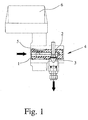
- the end Fig. 1 apparent magnetic-inductive flowmeter according to a first preferred embodiment of the invention comprises a ceramic measuring tube 1, which is provided at its right end in one piece with a valve housing 2.
- a movable valve body 3 is provided which can be controlled such that the valve 4 formed by the valve housing 2 and the valve body 3 is opened or closed.
- the measuring tube 1 and the valve housing 2 are made of a common ceramic workpiece, so that a one-piece construction is achieved, in which the measuring tube 1 merges seamlessly with the valve housing 2.
- flow measuring measuring electrodes 5 are provided which are sintered into the measuring tube 1 and extend into the interior of the measuring tube 1, so that they can come into galvanic contact with the flowing through the measuring tube 1 medium.
- the valve 4 is thus arranged in the flow direction behind the flow meter.
- the measured signal picked up by the measuring electrodes 5, namely the voltage induced in the flowing medium, is supplied to the measuring electronics 6, not shown in detail, which actuates the valve 4 in accordance with the preset values for the volumes of the flowing medium to be filled.
- the flow direction through the measuring tube 1 is horizontal and that the medium is discharged after detection of its flow through the valve 4 at right angles to it, namely down, for filling.
- the valve body 3 such a body is provided which is movable in the discharge direction of the valve and opposite thereto, while in the second preferred embodiment of the Invention, a rotatable valve body 3 is provided.
- a rotatable valve body 3 as in the Fig. 3 apparent third preferred embodiment of the invention, also be designed such that the outlet via the valve 4 takes place in the direction corresponding to the flow direction through the measuring tube 1.
Landscapes
- Physics & Mathematics (AREA)
- Fluid Mechanics (AREA)
- General Physics & Mathematics (AREA)
- Electromagnetism (AREA)
- Measuring Volume Flow (AREA)
Description
- Die Erfindung betrifft ein magnetisch-induktives Durchflußmeßgerät, mit einem Meßrohr zum Führen des Mediums und einer im Bereich des Meßrohrs angeordneten Durchflußmeßeinrichtung.
- Durchflußmeßgeräte, wie magnetisch-induktive Durchflußmeßgeräte, sind schon seit langer Zeit gut bekannt und werden vielfältig in unterschiedlichen Einsatzgebieten verwendet. Insbesondere magnetisch-induktive Durchflußmeßgeräte werden dabei auch bei der volumetrischen Abfüllung und Dosierung eingesetzt. Das heißt, daß magnetisch-induktive Durchflußmeßgeräte für Abfüllmaschinen verwendet werden, mit denen flüssige Lebensmittel, wie Getränke, in Behältnisse, z. B. Flaschen, abgefüllt werden.
- Das grundlegende Prinzip eines magnetisch-induktiven Durchflußmeßgeräts für strömende Medien geht bereits auf Faraday zurück, der im Jahre 1832 vorgeschlagen hat, das Prinzip der elektromagnetischen Induktion zur Strömungsgeschwindigkeitsmessung anzuwenden. Nach dem Faraday'schen Induktionsgesetz entsteht in einem strömenden Medium, das Ladungsträger mit sich führt und durch ein Magnetfeld hindurchfließt, eine elektrische Feldstärke senkrecht zur Strömungsrichtung und senkrecht zum Magnetfeld. Das Faraday'sche Induktionsgesetz wird bei einem magnetisch-induktiven Durchflußmeßgerät dadurch ausgenutzt, daß mittels einer Magnetspule ein Magnetfeld erzeugt wird, das eine Magnetfeldkomponente aufweist, die senkrecht zur Strömungsrichtung verläuft. Innerhalb dieses Magnetfelds liefert jedes sich durch das Magnetfeld bewegende und eine gewisse Anzahl von Ladungsträgern aufweisende Volumenelement des strömenden Mediums mit der in diesem Volumenelement entstehenden Feldstärke einen Beitrag zu einer über Meßelektroden abgreifbaren Meßspannung.
- Die Meßelektroden werden bei den bekannten magnetisch-induktiven Durchflußmeßgeräten derart ausgeführt, daß sie entweder galvanisch oder kapazitiv mit dem strömenden Medium gekoppelt sind. Ein besonderes Merkmal der magnetisch-induktiven Durchflußmeßgeräte ist ferner die Proportionalität zwischen der Meßspannung und der über den Querschnitt des Meßrohrs gemittelten Strömungsgeschwindigkeit des Mediums, d. h. zwischen Meßspannung und Volumenstrom.
- Wenigstens im Bereich der Meßelektroden ist es erforderlich, daß der Innenbereich des Meßrohrs elektrisch isolierend ist oder eine elektrisch isolierende Auskleidung aufweist. Insbesondere kann dazu vorgesehen sein, daß das Meßrohr aus einer Keramik hergestellt ist, in die die Meßelektroden z. B. eingesintert sind.
- Bei der Verwendung eines magnetisch-induktiven Durchflußmeßgeräts für eine Abfüllmäschine, die zum Abfüllen von flüssigen Lebensmitteln dient, sind zwei Anforderungen von wesentlicher Bedeutung: Erstens muß den hygienischen Ansprüchen entsprochen werden, was bedeutet, daß die Leitungen und Anschlüsse sowie die Übergänge zwischen einzelnen Bauteilen hygienischen Standards entsprechen müssen. Zweitens muß ein für eine Abfüllmäschine vorgesehenes magnetisch-induktives Durchflußmeßgerät hinreichend kleinbauend sein, damit die Abfüllmaschine auf platzsparende Weise mit einer Vielzahl derartiger magnetisch-induktiver Durchflußmeßgeräte ausgestattet werden kann
DE102004028576 ,EP1586533 oderEP0110189 offenbaren jeweils ein magnetisch-induktives Durchflussmessgerät nach dem Obergriff von Anspruch 1. - Vor diesem Hintergrund ist es die Aufgabe der Erfindung, ein magnetisch-induktives Durchflussmessgerät gemäß des Anspruchs 1, anzugeben, das kompakt ist und auf einfache Weise den für Abfüllmaschinen geltenden Hygienestandards entsprechen kann.
- Ausgehend von dem eingangs beschriebenen Durchflußmeßgerät ist diese Aufgabe dadurch gelöst, daß ein Ventilgehäuse vorgesehen ist, das einstückig mit dem Meßrohr ausgebildet ist.
- Maßgeblicher Bestandteil einer Abfüllmaschine ist in der Regel immer ein Ventil, das derart angesteuert wird, daß genau eine vorbestimmte, durch ein Durchflußmeßgerät ermittelte Menge des abzufüllenden Mediums in ein Behältnis abgefüllt wird. Erfindungsgemäß ist in diesem Zusammenhang nun vorgesehen, daß das Meßrohr des Durchflußmeßgeräts bereits in einstückiger Weise mit einem Ventilgehäuse versehen ist, so daß das Meßrohr mit dem Ventil eine gemeinsame Baueinheit bildet. Auf diese Weise wird eine kompakte Konstruktion bereitgestellt, die platzsparend und einfach handhabbar ist, wobei aufgrund einer fehlenden Übergangsfläche vom Meßrohr auf das Ventilgehäuse auch unter hygienischen Gesichtspunkten eine einfache Handhabung gewährleistet wird.
- Grundsätzlich gibt es eine Mehrzahl von Möglichkeiten, das Ventilgehäuse und das Meßrohr einstückig miteinander auszugestalten. Gemäß einer bevorzugten Weiterbildung der Erfindung ist jedoch vorgesehen, daß das Ventilgehäuse einstückig an das Meßrohr angefügt ist, z. B. angegossen ist. Gemäß einer alternativen bevorzugten Ausführungsform der Erfindung ist vorgesehen, daß das Ventilgehäuse und das Meßrohr aus einem gemeinsamen Werkstück hergestellt sind. Gemäß der Erfindung, die insbesondere für ein magnetisch-induktives Durchflußmeßgerät geeignet ist, ist vorgesehen, daß das Meßrohr und das Ventilgehäuse aus Keramik hergestellt sind, insbesondere nämlich aus einem einzigen gemeinsamen Keramikwerkstück.
- Sind das Meßrohr und das Ventilgehäuse aus Keramik hergestellt, so ist gemäß der Erfindung vorgesehen, daß in dem Ventilgehäuse ein bewegbarer Ventilkörper angeordnet ist, der ebenfalls aus Keramik hergestellt ist, insbesondere nämlich vorzugsweise aus der gleichen Keramik wie das Ventilgehäuse und damit das Meßrohr. Dabei ist gemäß der Erfindung ferner vorgesehen, daß zwischen dem Ventilgehäuse und dem Ventilkörper keine separate Dichtung bereitgestellt wird. Vielmehr liegen die beiden Keramikflächen des Ventilgehäuses einerseits und des Ventilkörpers andererseits direkt aufeinander auf, wobei aufgrund ihrer erzielbaren extremen Glattheit bereits ohne separate Dichtung eine hinreichende Dichtwirkung erzielt wird.
- Bezüglich der Anordnung des Ventilgehäuses gibt es mehrere Möglichkeiten. Gemäß der Erfindung ist jedoch vorgesehen, daß das Ventilgehäuse in Strömungsrichtung gesehen hinter der Durchflußmeßeinrichtung angeordnet ist.
- Nachfolgend wird die Erfindung anhand bevorzugter Ausführungsbeispiele unter Bezugnahme auf die Zeichnung weiter im Detail erläutert. In der Zeichnung zeigt
- Fig. 1
- ein magnetisch-induktives Durchflußmeßgerät gemäß einem ersten bevorzugten Ausführungsbeispiel der Erfindung, teilweise im Schnitt,
- Fig. 2
- ein magnetisch-induktives Durchflußmeßgerät gemäß einem zweiten bevorzugten Ausführungsbeispiel der Erfindung, teilweise im Schnitt, und
- Fig. 3
- ein magnetisch-induktives Durchflußmeßgerät gemäß einem dritten bevorzugten Ausführungsbeispiel der Erfindung, ebenfalls teilweise im Schnitt.
- Das aus
Fig. 1 ersichtliche magnetisch-induktive Durchflußmeßgerät gemäß einem ersten bevorzugten Ausführungsbeispiel der Erfindung weist ein keramisches Meßrohr 1 auf, das an seinem rechten Ende in einstückiger Weise mit einem Ventilgehäuse 2 versehen ist. In dem Ventilgehäuse 2 ist ein bewegbarer Ventilkörper 3 vorgesehen, der derart angesteuert werden kann, daß das durch das Ventilgehäuse 2 und den Ventilkörper 3 gebildete Ventil 4 geöffnet oder geschlossen wird. Das Meßrohr 1 und das Ventilgehäuse 2 sind aus einem gemeinsamen Werkstück aus Keramik hergestellt, so daß eine einstückige Konstruktion erzielt wird, bei der das Meßrohr 1 nahtlos auf das Ventilgehäuse 2 übergeht. - Als Bestandteil einer im Bereich des Meßrohrs 1 angeordneten Durchflußmeßeinrichtung sind Meßelektroden 5 vorgesehen, die in das Meßrohr 1 eingesintert sind und bis in das Innere des Meßrohrs 1 hineinreichen, so daß sie mit dem durch das Meßrohr 1 strömenden Medium in galvanisch leitenden Kontakt kommen können. Wie durch die dicken Pfeile für die Strömungsrichtung angedeutet, ist das Ventil 4 damit in Strömungsrichtung gesehen hinter der Durchflußmeßeinrichtung angeordnet.
- Das über die Meßelektroden 5 abgegriffene Meßsignal, nämlich die in dem strömenden Medium induzierte Spannung, wird der im einzelnen nicht dargestellten Meßelektronik 6 zugeführt, die entsprechend den eingestellten Vorgabewerten für die abzufüllenden Volumina des strömenden Mediums das Ventil 4 ansteuert.
- Bei dem vorliegend beschriebenen ersten bevorzugten Ausführungsbeispiel der Erfindung ist vorgesehen, daß die Flußrichtung durch das Meßrohr 1 waagerecht ist und daß das Medium nach Erfassung seines Durchflusses über das Ventil 4 rechtwinklig dazu, nämlich nach unten, zum Abfüllen abgegeben wird. Entsprechendes ist auch bei dem in
Fig. 2 gezeigten magnetisch-induktiven Durchflußmeßgerät gemäß einem zweiten bevorzugten Ausführungsbeispiel der Erfindung vorgesehen, wobei jedoch bei dem ersten bevorzugten Ausführungsbeispiel der Erfindung als Ventilkörper 3 ein derartiger Körper vorgesehen ist, der in Abgaberichtung des Ventils und entgegengesetzt dazu bewegbar ist, während bei dem zweiten bevorzugten Ausführungsbeispiel der Erfindung ein drehbarer Ventilkörper 3 vorgesehen ist. Ein derartiger drehbarer Ventilkörper 3 kann, wie bei dem ausFig. 3 ersichtlichen dritten bevorzugten Ausführungsbeispiel der Erfindung ersichtlich, auch derart ausgebildet sein, daß der Auslaß über das Ventil 4 in der Richtung erfolgt, die der Durchströmrichtung durch das Meßrohr 1 entspricht.
Claims (4)
- Magnetisch-induktives Durchflussmessgerät zur Durchflussmessung eines strömenden Mediums, mit einem Messrohr (1) zum Führen des Mediums und einer im Bereich des Messrohrs (1) vorgesehenen Durchflussmesseinrichtung (6), wobei ein Ventilgehäuse (2) in Strömungsrichtung gesehen hinter der Durchflussmesseinrichtung (6) vorgesehen ist, wobei das Messrohr (1) und das Ventilgehäuse (2) aus Keramik hergestellt sind und wobei in dem Ventilgehäuse (2) ein bewegbarer Ventilkörper (3) vorgesehen ist, der ebenfalls aus Keramik hergestellt ist,
dadurch gekennzeichnet,
dass das Ventilgehäuse (2) einstückig mit dem Messrohr (1) ausgebildet ist und dass zwischen dem Ventilgehäuse (2) und dem Ventilkörper (3) keine separate Dichtung vorgesehen ist. - Durchflussmessgerät nach Anspruch 1, dadurch gekennzeichnet, dass das Ventilgehäuse (2) einstückig an das Messrohr (1) angefügt ist.
- Durchflussmessgerät nach Anspruch 1, dadurch gekennzeichnet, dass das Ventilgehäuse (2) und das Messrohr (1) aus einem gemeinsamen Werkstück hergestellt sind.
- Durchflussmessgerät nach einem der Ansprüche 1 bis 3, dadurch gekennzeichnet, dass die Durchflussmesseinrichtung ein in dem Messrohr (1) vorgesehenes Paar von Messelektroden (5) aufweist.
Applications Claiming Priority (1)
| Application Number | Priority Date | Filing Date | Title |
|---|---|---|---|
| DE102006045976A DE102006045976B4 (de) | 2006-09-27 | 2006-09-27 | Durchflussmessgerät |
Publications (3)
| Publication Number | Publication Date |
|---|---|
| EP1906156A2 EP1906156A2 (de) | 2008-04-02 |
| EP1906156A3 EP1906156A3 (de) | 2008-12-24 |
| EP1906156B1 true EP1906156B1 (de) | 2018-05-02 |
Family
ID=38720684
Family Applications (1)
| Application Number | Title | Priority Date | Filing Date |
|---|---|---|---|
| EP07018686.1A Not-in-force EP1906156B1 (de) | 2006-09-27 | 2007-09-24 | Durchflussmessgerät |
Country Status (4)
| Country | Link |
|---|---|
| US (1) | US7819020B2 (de) |
| EP (1) | EP1906156B1 (de) |
| JP (1) | JP5364254B2 (de) |
| DE (1) | DE102006045976B4 (de) |
Families Citing this family (20)
| Publication number | Priority date | Publication date | Assignee | Title |
|---|---|---|---|---|
| DE102006014103B4 (de) * | 2006-03-24 | 2008-04-24 | Khs Ag | Füllelement zum Füllen von Flaschen oder dergleichen Behälter mit einem flüssigen Füllgut sowie Füllmaschine mit derartigen Füllelementen |
| DE102008057755B4 (de) * | 2008-11-17 | 2015-12-17 | Krohne Ag | Magnetisch-induktives Durchflußmeßgerät |
| US8294292B2 (en) * | 2009-04-22 | 2012-10-23 | Rain Bird Corporation | Power supply system |
| PT2273117E (pt) * | 2009-06-03 | 2013-10-04 | Nestec Sa | Processo para detectar a formação de incrustações numa máquina de preparação de bebidas |
| DE102010046641A1 (de) | 2010-09-25 | 2012-03-29 | Arne Feldmeier | Verfahren und Vorrichtung zur Volumenstrombestimmung fluiddurchströmter Leitungsnetze |
| US8740177B2 (en) | 2011-07-05 | 2014-06-03 | Rain Bird Corporation | Eccentric diaphragm valve |
| DE102011110950A1 (de) * | 2011-08-12 | 2013-02-14 | Altek Gesellschaft für allg. Landtechnik mbH | Abschaltventil für eine fluidführende Vorrichtung eines Nutzfahrzeugs |
| WO2018013857A1 (en) | 2016-07-13 | 2018-01-18 | Rain Bird Corporation | Flow sensor |
| US10473494B2 (en) | 2017-10-24 | 2019-11-12 | Rain Bird Corporation | Flow sensor |
| USD873995S1 (en) | 2018-06-01 | 2020-01-28 | ClearTrac Technologies, LLC | Uroflowmeter |
| JP7326348B2 (ja) | 2018-06-01 | 2023-08-15 | クリアトラック テクノロジーズ,エルエルシー | 尿流量計 |
| USD932632S1 (en) | 2018-07-13 | 2021-10-05 | ClearTrac Technologies, LLC | Uroflowmeter |
| US11662242B2 (en) | 2018-12-31 | 2023-05-30 | Rain Bird Corporation | Flow sensor gauge |
| USD932648S1 (en) | 2019-03-08 | 2021-10-05 | ClearTrac Technologies, LLC | Uroflowmeter |
| DE102020213512A1 (de) | 2020-10-27 | 2022-04-28 | Siemens Aktiengesellschaft | Messeinrichtung mit Pitot-Durchflussmesser und Verfahren zu ihrer Herstellung |
| CN114645969B (zh) * | 2022-04-03 | 2025-03-25 | 杭州云谷科技股份有限公司 | 对开结构的一体化流量测量和调节装置 |
| CN114704686B (zh) * | 2022-04-03 | 2025-04-18 | 杭州云谷科技股份有限公司 | 高精度流量测量和调节一体化装置 |
| DE102022115308B3 (de) * | 2022-06-20 | 2023-11-09 | Krohne Ag | Verfahren zum Bestimmen eines Durchflusses eines Mediums mit einem magnetisch-induktiven Durchflussmessgerät, Verfahren zum Betreiben einer Abfüllanlage mit einem magnetisch-induktiven Durchflussmessgerät, magnetisch-induktives Durchflussmessgerät und Abfüllanlage mit einem magnetisch-induktiven Durchflussmessgerät |
| US12443208B2 (en) | 2023-02-08 | 2025-10-14 | Rain Bird Corporation | Control zone devices, systems and methods |
| US12498049B2 (en) | 2024-03-29 | 2025-12-16 | Rain Bird Corporation | Zone control devices, systems and methods |
Citations (2)
| Publication number | Priority date | Publication date | Assignee | Title |
|---|---|---|---|---|
| EP0110189A1 (de) * | 1982-11-09 | 1984-06-13 | Pirzer, Carl | Verfahren zum Steuern einer Füllmaschine, insbesondere Flaschen-füllmaschine sowie Anordnung zur Durchführung dieses Verfahrens |
| EP0200563A2 (de) * | 1985-05-03 | 1986-11-05 | Robert James Weir | Ventil für eine Prozessleitung |
Family Cites Families (33)
| Publication number | Priority date | Publication date | Assignee | Title |
|---|---|---|---|---|
| US3795144A (en) * | 1972-02-17 | 1974-03-05 | R Marchesi | Tamper-proof water meter |
| GB1424875A (en) | 1972-06-19 | 1976-02-11 | Sybron Corp | Electromagnetic flow transducers |
| US3856033A (en) * | 1973-02-22 | 1974-12-24 | Scott Environmental Tech | Dynamic gas blending |
| JPS5057971A (de) * | 1973-09-26 | 1975-05-20 | ||
| US4055496A (en) * | 1974-04-19 | 1977-10-25 | National Medical Care, Inc. | Dialysis apparatus |
| US4198225A (en) * | 1979-04-20 | 1980-04-15 | The United States Of America As Represented By The Secretary Of The Army | Microchannel plate in wall fabrication, method and apparatus |
| DE3003650A1 (de) * | 1980-02-01 | 1981-08-06 | Rolf 4800 Bielefeld Quisbrok | Vorrichtung zur ermittlung des waermeverbrauchs bei warmwasser-umlaufheizungen |
| FR2487944A1 (fr) * | 1980-07-29 | 1982-02-05 | Favi Laiton Injecte | Element moule a tubulures associe a au moins un robinet dont une desdites tubulures constitue le corps |
| JPS6212053U (de) * | 1985-07-05 | 1987-01-24 | ||
| US4805862A (en) * | 1987-07-30 | 1989-02-21 | Washington Suburban Sanitary Commission | Harness for supporting a meter on a fire hydrant and the combination of a meter, fire hydrant and harness |
| JPH0610256Y2 (ja) * | 1988-05-07 | 1994-03-16 | 横河電機株式会社 | セラミックス電磁流量計 |
| JPH0291518A (ja) * | 1988-09-29 | 1990-03-30 | Yokogawa Electric Corp | 微小口径電磁流量計 |
| US4986445A (en) * | 1989-12-04 | 1991-01-22 | Gilbarco Inc. | Gasoline dispenser with valve control through an air gap |
| US5085076A (en) * | 1990-11-29 | 1992-02-04 | Ames Company, Inc. | Integrated water strainer, meter, and crossover check valve |
| US5381926A (en) * | 1992-06-05 | 1995-01-17 | The Coca-Cola Company | Beverage dispensing value and method |
| US5567875A (en) * | 1995-05-05 | 1996-10-22 | Schlumberger Industries, Inc. | Modular gas meter assembly and associated manifold |
| DE19540441A1 (de) * | 1995-10-27 | 1997-04-30 | Schubert & Salzer Control Syst | Mikroprozessorgesteuerter Stellungsregler |
| US6321766B1 (en) * | 1997-02-11 | 2001-11-27 | Richard D. Nathenson | Electromagnetic flow control valve for a liquid metal with built-in flow measurement |
| WO2000050793A1 (en) * | 1999-02-24 | 2000-08-31 | Water Valves Australia Pty. Ltd. | Water meter fixtures |
| DE19913685A1 (de) * | 1999-03-25 | 2000-09-28 | Attendorner Spezial Armaturen | Koaxiales Anschlußstück zur Aufnahme eines Meßgerätes |
| GB9910607D0 (en) * | 1999-05-08 | 1999-07-07 | Imi Cornelius Uk Ltd | Beverage dispenser |
| EP1254332B1 (de) * | 2000-01-25 | 2003-10-01 | Alois Schwarz | Ventil, insbesondere druckreduzierventil |
| US6792799B2 (en) * | 2002-04-11 | 2004-09-21 | Michael Brent Ford | Positive flow meter |
| US7152621B1 (en) * | 2003-09-19 | 2006-12-26 | R.W. Lyall & Company, Inc. | Integrated gas meters bar device and locking shut-off valve |
| IL151748A0 (en) * | 2002-09-12 | 2003-04-10 | Aran Res & Dev Ltd | Fluid metering method and system |
| JP4431940B2 (ja) * | 2003-04-10 | 2010-03-17 | 旭有機材工業株式会社 | 配管部材の接続構造 |
| EP1706663B1 (de) * | 2004-01-20 | 2013-07-17 | Fisher Controls International Llc | Einspritzsystem für erdgasgeruchsmittel |
| KR100562770B1 (ko) * | 2004-03-05 | 2006-03-20 | 주식회사 승광 | 연수기용 통합 감압밸브 |
| DE102004017211B3 (de) * | 2004-04-10 | 2006-04-27 | Khs Maschinen- Und Anlagenbau Ag | Füllelement zum Füllen von Flaschen oder dergleichen Behälter mit einem flüssigen Füllgut |
| US7416542B2 (en) * | 2004-04-30 | 2008-08-26 | Medtronic, Inc. | Open circuit gravity-assisted uroflowmeter |
| DE102004028576A1 (de) * | 2004-06-15 | 2005-12-29 | Krones Ag | Füller zum Abfüllen einer Flüssigkeit und Verfahren zum Messen einer Flüssigkeitsmenge |
| KR100755297B1 (ko) * | 2005-12-02 | 2007-09-05 | 주식회사 우일하이테크 | 제어밸브 일체형 차압식 유량계 |
| EP1862429A1 (de) * | 2006-05-30 | 2007-12-05 | Dresser Wayne Ab | Luftabscheider für eine Kraftstoffzapfanlage |
-
2006
- 2006-09-27 DE DE102006045976A patent/DE102006045976B4/de not_active Revoked
-
2007
- 2007-09-24 EP EP07018686.1A patent/EP1906156B1/de not_active Not-in-force
- 2007-09-27 US US11/862,737 patent/US7819020B2/en not_active Expired - Fee Related
- 2007-09-27 JP JP2007251148A patent/JP5364254B2/ja not_active Expired - Fee Related
Patent Citations (2)
| Publication number | Priority date | Publication date | Assignee | Title |
|---|---|---|---|---|
| EP0110189A1 (de) * | 1982-11-09 | 1984-06-13 | Pirzer, Carl | Verfahren zum Steuern einer Füllmaschine, insbesondere Flaschen-füllmaschine sowie Anordnung zur Durchführung dieses Verfahrens |
| EP0200563A2 (de) * | 1985-05-03 | 1986-11-05 | Robert James Weir | Ventil für eine Prozessleitung |
Also Published As
| Publication number | Publication date |
|---|---|
| DE102006045976B4 (de) | 2013-01-31 |
| JP2008083055A (ja) | 2008-04-10 |
| EP1906156A3 (de) | 2008-12-24 |
| DE102006045976A1 (de) | 2008-04-17 |
| US20080087100A1 (en) | 2008-04-17 |
| EP1906156A2 (de) | 2008-04-02 |
| US7819020B2 (en) | 2010-10-26 |
| JP5364254B2 (ja) | 2013-12-11 |
Similar Documents
| Publication | Publication Date | Title |
|---|---|---|
| EP1906156A2 (de) | Durchflussmessgerät | |
| EP2533023B1 (de) | Magnetiisch-induktives Durchflussmessgerät | |
| EP2413107B1 (de) | Magnetisch-induktives Durchflussmessgerät | |
| DE10118002B4 (de) | Magnetisch-induktives Durchflußmeßverfahren und magnetisch-induktives Durchflußmeßgerät | |
| DE10240024B4 (de) | Magnetisch-induktives Durchflußmeßgerät | |
| DE202009017275U1 (de) | Magnetisch-induktiver Durchflussmesser | |
| DE102004062680A1 (de) | In-Line-Meßgerät mit einem Meßrohr und Verfahren zu dessen Herstellung | |
| EP0892252B1 (de) | Magnetisch-induktiver Durchflussaufnehmer mit einer galvanischen Elektrode | |
| EP2169359A1 (de) | Messarmatur und Verfahren zur Ermittlung eines Differenz- oder Summenvolumenstromes | |
| CH669765A5 (de) | ||
| WO2007110310A1 (de) | Magnetisch-induktives durchflussmessgerät | |
| DE102010056077A1 (de) | Magnetisch-induktiver Durchflussmesser mit einer innenwandseitig des Messrohres angeordneten Auskleidung | |
| DE102005028723A1 (de) | Magnetisch-induktives Durchflussmessgerät | |
| EP0362784B1 (de) | Gerät zum Erkennen des Durchflusses eines viskosen Mediums durch eine Leitung | |
| DE102009045274A1 (de) | Magnetisch induktives Durchflussmessgerät | |
| DE102018132621A1 (de) | Vorrichtung und Verfahren zum Befüllen eines Behälters mit einem Füllprodukt | |
| WO2006034851A1 (de) | Wirbeldurchflussmesser | |
| DE4416892C2 (de) | Sensor zur Messung der Leitfähigkeit flüssiger Medien | |
| DE202014104841U1 (de) | Vorrichtung zum Befüllen eines Behälters mit einem Füllprodukt | |
| DE102018124069A1 (de) | Magnetisch-induktives Durchflussmessgerät mit Sensor zur Erfassung einer weiteren Messgröße | |
| DE102006015074B4 (de) | Magnetisch-induktiver Durchflussmesser mit einer Isolierschicht und Verfahren zu dessen Herstellung | |
| DE102006018231B4 (de) | Messeinrichtung zur volumetrischen Messung einer Flüssigkeit | |
| DE102005030713A1 (de) | Messstoffberührende Elektrode sowie Verfahren zur Herstellung derselben | |
| EP1770378A2 (de) | Vorrichtung zum Messen der Dosiermenge von Spülzusätzen | |
| EP2080995A1 (de) | Magnetisch-induktiver Durchflussmesser |
Legal Events
| Date | Code | Title | Description |
|---|---|---|---|
| PUAI | Public reference made under article 153(3) epc to a published international application that has entered the european phase |
Free format text: ORIGINAL CODE: 0009012 |
|
| AK | Designated contracting states |
Kind code of ref document: A2 Designated state(s): AT BE BG CH CY CZ DE DK EE ES FI FR GB GR HU IE IS IT LI LT LU LV MC MT NL PL PT RO SE SI SK TR |
|
| AX | Request for extension of the european patent |
Extension state: AL BA HR MK YU |
|
| RIN1 | Information on inventor provided before grant (corrected) |
Inventor name: DETLEF, JACOBI Inventor name: UDO, STEVENS Inventor name: NEUBURGER, STEFAN |
|
| PUAL | Search report despatched |
Free format text: ORIGINAL CODE: 0009013 |
|
| AK | Designated contracting states |
Kind code of ref document: A3 Designated state(s): AT BE BG CH CY CZ DE DK EE ES FI FR GB GR HU IE IS IT LI LT LU LV MC MT NL PL PT RO SE SI SK TR |
|
| AX | Request for extension of the european patent |
Extension state: AL BA HR MK RS |
|
| 17P | Request for examination filed |
Effective date: 20090622 |
|
| AKX | Designation fees paid |
Designated state(s): AT BE BG CH CY CZ DE DK EE ES FI FR GB GR HU IE IS IT LI LT LU LV MC MT NL PL PT RO SE SI SK TR |
|
| 17Q | First examination report despatched |
Effective date: 20090810 |
|
| GRAP | Despatch of communication of intention to grant a patent |
Free format text: ORIGINAL CODE: EPIDOSNIGR1 |
|
| INTG | Intention to grant announced |
Effective date: 20171103 |
|
| GRAS | Grant fee paid |
Free format text: ORIGINAL CODE: EPIDOSNIGR3 |
|
| GRAA | (expected) grant |
Free format text: ORIGINAL CODE: 0009210 |
|
| AK | Designated contracting states |
Kind code of ref document: B1 Designated state(s): AT BE BG CH CY CZ DE DK EE ES FI FR GB GR HU IE IS IT LI LT LU LV MC MT NL PL PT RO SE SI SK TR |
|
| REG | Reference to a national code |
Ref country code: GB Ref legal event code: FG4D Free format text: NOT ENGLISH |
|
| REG | Reference to a national code |
Ref country code: CH Ref legal event code: EP Ref country code: AT Ref legal event code: REF Ref document number: 995775 Country of ref document: AT Kind code of ref document: T Effective date: 20180515 |
|
| REG | Reference to a national code |
Ref country code: DE Ref legal event code: R096 Ref document number: 502007016164 Country of ref document: DE Ref country code: IE Ref legal event code: FG4D Free format text: LANGUAGE OF EP DOCUMENT: GERMAN |
|
| REG | Reference to a national code |
Ref country code: DE Ref legal event code: R096 Ref document number: 502007016164 Country of ref document: DE |
|
| REG | Reference to a national code |
Ref country code: NL Ref legal event code: MP Effective date: 20180502 |
|
| REG | Reference to a national code |
Ref country code: LT Ref legal event code: MG4D Ref country code: FR Ref legal event code: PLFP Year of fee payment: 12 |
|
| PG25 | Lapsed in a contracting state [announced via postgrant information from national office to epo] |
Ref country code: ES Free format text: LAPSE BECAUSE OF FAILURE TO SUBMIT A TRANSLATION OF THE DESCRIPTION OR TO PAY THE FEE WITHIN THE PRESCRIBED TIME-LIMIT Effective date: 20180502 Ref country code: SE Free format text: LAPSE BECAUSE OF FAILURE TO SUBMIT A TRANSLATION OF THE DESCRIPTION OR TO PAY THE FEE WITHIN THE PRESCRIBED TIME-LIMIT Effective date: 20180502 Ref country code: BG Free format text: LAPSE BECAUSE OF FAILURE TO SUBMIT A TRANSLATION OF THE DESCRIPTION OR TO PAY THE FEE WITHIN THE PRESCRIBED TIME-LIMIT Effective date: 20180802 Ref country code: LT Free format text: LAPSE BECAUSE OF FAILURE TO SUBMIT A TRANSLATION OF THE DESCRIPTION OR TO PAY THE FEE WITHIN THE PRESCRIBED TIME-LIMIT Effective date: 20180502 Ref country code: FI Free format text: LAPSE BECAUSE OF FAILURE TO SUBMIT A TRANSLATION OF THE DESCRIPTION OR TO PAY THE FEE WITHIN THE PRESCRIBED TIME-LIMIT Effective date: 20180502 |
|
| PG25 | Lapsed in a contracting state [announced via postgrant information from national office to epo] |
Ref country code: GR Free format text: LAPSE BECAUSE OF FAILURE TO SUBMIT A TRANSLATION OF THE DESCRIPTION OR TO PAY THE FEE WITHIN THE PRESCRIBED TIME-LIMIT Effective date: 20180803 Ref country code: NL Free format text: LAPSE BECAUSE OF FAILURE TO SUBMIT A TRANSLATION OF THE DESCRIPTION OR TO PAY THE FEE WITHIN THE PRESCRIBED TIME-LIMIT Effective date: 20180502 Ref country code: LV Free format text: LAPSE BECAUSE OF FAILURE TO SUBMIT A TRANSLATION OF THE DESCRIPTION OR TO PAY THE FEE WITHIN THE PRESCRIBED TIME-LIMIT Effective date: 20180502 |
|
| PG25 | Lapsed in a contracting state [announced via postgrant information from national office to epo] |
Ref country code: PT Free format text: LAPSE BECAUSE OF FAILURE TO SUBMIT A TRANSLATION OF THE DESCRIPTION OR TO PAY THE FEE WITHIN THE PRESCRIBED TIME-LIMIT Effective date: 20180903 |
|
| PG25 | Lapsed in a contracting state [announced via postgrant information from national office to epo] |
Ref country code: CZ Free format text: LAPSE BECAUSE OF FAILURE TO SUBMIT A TRANSLATION OF THE DESCRIPTION OR TO PAY THE FEE WITHIN THE PRESCRIBED TIME-LIMIT Effective date: 20180502 Ref country code: RO Free format text: LAPSE BECAUSE OF FAILURE TO SUBMIT A TRANSLATION OF THE DESCRIPTION OR TO PAY THE FEE WITHIN THE PRESCRIBED TIME-LIMIT Effective date: 20180502 Ref country code: SK Free format text: LAPSE BECAUSE OF FAILURE TO SUBMIT A TRANSLATION OF THE DESCRIPTION OR TO PAY THE FEE WITHIN THE PRESCRIBED TIME-LIMIT Effective date: 20180502 Ref country code: EE Free format text: LAPSE BECAUSE OF FAILURE TO SUBMIT A TRANSLATION OF THE DESCRIPTION OR TO PAY THE FEE WITHIN THE PRESCRIBED TIME-LIMIT Effective date: 20180502 Ref country code: DK Free format text: LAPSE BECAUSE OF FAILURE TO SUBMIT A TRANSLATION OF THE DESCRIPTION OR TO PAY THE FEE WITHIN THE PRESCRIBED TIME-LIMIT Effective date: 20180502 Ref country code: PL Free format text: LAPSE BECAUSE OF FAILURE TO SUBMIT A TRANSLATION OF THE DESCRIPTION OR TO PAY THE FEE WITHIN THE PRESCRIBED TIME-LIMIT Effective date: 20180502 |
|
| REG | Reference to a national code |
Ref country code: DE Ref legal event code: R097 Ref document number: 502007016164 Country of ref document: DE |
|
| PG25 | Lapsed in a contracting state [announced via postgrant information from national office to epo] |
Ref country code: IT Free format text: LAPSE BECAUSE OF FAILURE TO SUBMIT A TRANSLATION OF THE DESCRIPTION OR TO PAY THE FEE WITHIN THE PRESCRIBED TIME-LIMIT Effective date: 20180502 |
|
| PLBE | No opposition filed within time limit |
Free format text: ORIGINAL CODE: 0009261 |
|
| STAA | Information on the status of an ep patent application or granted ep patent |
Free format text: STATUS: NO OPPOSITION FILED WITHIN TIME LIMIT |
|
| 26N | No opposition filed |
Effective date: 20190205 |
|
| PG25 | Lapsed in a contracting state [announced via postgrant information from national office to epo] |
Ref country code: MC Free format text: LAPSE BECAUSE OF FAILURE TO SUBMIT A TRANSLATION OF THE DESCRIPTION OR TO PAY THE FEE WITHIN THE PRESCRIBED TIME-LIMIT Effective date: 20180502 |
|
| GBPC | Gb: european patent ceased through non-payment of renewal fee |
Effective date: 20180924 |
|
| PG25 | Lapsed in a contracting state [announced via postgrant information from national office to epo] |
Ref country code: SI Free format text: LAPSE BECAUSE OF FAILURE TO SUBMIT A TRANSLATION OF THE DESCRIPTION OR TO PAY THE FEE WITHIN THE PRESCRIBED TIME-LIMIT Effective date: 20180502 |
|
| REG | Reference to a national code |
Ref country code: BE Ref legal event code: MM Effective date: 20180930 |
|
| REG | Reference to a national code |
Ref country code: IE Ref legal event code: MM4A |
|
| PG25 | Lapsed in a contracting state [announced via postgrant information from national office to epo] |
Ref country code: LU Free format text: LAPSE BECAUSE OF NON-PAYMENT OF DUE FEES Effective date: 20180924 |
|
| PG25 | Lapsed in a contracting state [announced via postgrant information from national office to epo] |
Ref country code: IE Free format text: LAPSE BECAUSE OF NON-PAYMENT OF DUE FEES Effective date: 20180924 |
|
| PG25 | Lapsed in a contracting state [announced via postgrant information from national office to epo] |
Ref country code: BE Free format text: LAPSE BECAUSE OF NON-PAYMENT OF DUE FEES Effective date: 20180930 |
|
| PG25 | Lapsed in a contracting state [announced via postgrant information from national office to epo] |
Ref country code: GB Free format text: LAPSE BECAUSE OF NON-PAYMENT OF DUE FEES Effective date: 20180924 |
|
| REG | Reference to a national code |
Ref country code: AT Ref legal event code: MM01 Ref document number: 995775 Country of ref document: AT Kind code of ref document: T Effective date: 20180924 |
|
| PG25 | Lapsed in a contracting state [announced via postgrant information from national office to epo] |
Ref country code: MT Free format text: LAPSE BECAUSE OF FAILURE TO SUBMIT A TRANSLATION OF THE DESCRIPTION OR TO PAY THE FEE WITHIN THE PRESCRIBED TIME-LIMIT Effective date: 20180502 Ref country code: AT Free format text: LAPSE BECAUSE OF NON-PAYMENT OF DUE FEES Effective date: 20180924 |
|
| PG25 | Lapsed in a contracting state [announced via postgrant information from national office to epo] |
Ref country code: TR Free format text: LAPSE BECAUSE OF FAILURE TO SUBMIT A TRANSLATION OF THE DESCRIPTION OR TO PAY THE FEE WITHIN THE PRESCRIBED TIME-LIMIT Effective date: 20180502 |
|
| PG25 | Lapsed in a contracting state [announced via postgrant information from national office to epo] |
Ref country code: HU Free format text: LAPSE BECAUSE OF FAILURE TO SUBMIT A TRANSLATION OF THE DESCRIPTION OR TO PAY THE FEE WITHIN THE PRESCRIBED TIME-LIMIT; INVALID AB INITIO Effective date: 20070924 |
|
| PG25 | Lapsed in a contracting state [announced via postgrant information from national office to epo] |
Ref country code: CY Free format text: LAPSE BECAUSE OF FAILURE TO SUBMIT A TRANSLATION OF THE DESCRIPTION OR TO PAY THE FEE WITHIN THE PRESCRIBED TIME-LIMIT Effective date: 20180502 |
|
| PG25 | Lapsed in a contracting state [announced via postgrant information from national office to epo] |
Ref country code: IS Free format text: LAPSE BECAUSE OF FAILURE TO SUBMIT A TRANSLATION OF THE DESCRIPTION OR TO PAY THE FEE WITHIN THE PRESCRIBED TIME-LIMIT Effective date: 20180902 |
|
| PGFP | Annual fee paid to national office [announced via postgrant information from national office to epo] |
Ref country code: FR Payment date: 20210921 Year of fee payment: 15 Ref country code: CH Payment date: 20210920 Year of fee payment: 15 |
|
| PGFP | Annual fee paid to national office [announced via postgrant information from national office to epo] |
Ref country code: DE Payment date: 20211122 Year of fee payment: 15 |
|
| REG | Reference to a national code |
Ref country code: DE Ref legal event code: R119 Ref document number: 502007016164 Country of ref document: DE |
|
| REG | Reference to a national code |
Ref country code: CH Ref legal event code: PL |
|
| PG25 | Lapsed in a contracting state [announced via postgrant information from national office to epo] |
Ref country code: LI Free format text: LAPSE BECAUSE OF NON-PAYMENT OF DUE FEES Effective date: 20220930 Ref country code: FR Free format text: LAPSE BECAUSE OF NON-PAYMENT OF DUE FEES Effective date: 20220930 Ref country code: DE Free format text: LAPSE BECAUSE OF NON-PAYMENT OF DUE FEES Effective date: 20230401 Ref country code: CH Free format text: LAPSE BECAUSE OF NON-PAYMENT OF DUE FEES Effective date: 20220930 |