EP1906061B1 - Transmission downshift control method - Google Patents
Transmission downshift control method Download PDFInfo
- Publication number
- EP1906061B1 EP1906061B1 EP07018838A EP07018838A EP1906061B1 EP 1906061 B1 EP1906061 B1 EP 1906061B1 EP 07018838 A EP07018838 A EP 07018838A EP 07018838 A EP07018838 A EP 07018838A EP 1906061 B1 EP1906061 B1 EP 1906061B1
- Authority
- EP
- European Patent Office
- Prior art keywords
- clutch
- compounder
- gear box
- main gear
- speed
- Prior art date
- Legal status (The legal status is an assumption and is not a legal conclusion. Google has not performed a legal analysis and makes no representation as to the accuracy of the status listed.)
- Active
Links
Images

Classifications
-
- F—MECHANICAL ENGINEERING; LIGHTING; HEATING; WEAPONS; BLASTING
- F16—ENGINEERING ELEMENTS AND UNITS; GENERAL MEASURES FOR PRODUCING AND MAINTAINING EFFECTIVE FUNCTIONING OF MACHINES OR INSTALLATIONS; THERMAL INSULATION IN GENERAL
- F16H—GEARING
- F16H61/00—Control functions within control units of change-speed- or reversing-gearings for conveying rotary motion ; Control of exclusively fluid gearing, friction gearing, gearings with endless flexible members or other particular types of gearing
- F16H61/04—Smoothing ratio shift
- F16H61/0437—Smoothing ratio shift by using electrical signals
-
- F—MECHANICAL ENGINEERING; LIGHTING; HEATING; WEAPONS; BLASTING
- F16—ENGINEERING ELEMENTS AND UNITS; GENERAL MEASURES FOR PRODUCING AND MAINTAINING EFFECTIVE FUNCTIONING OF MACHINES OR INSTALLATIONS; THERMAL INSULATION IN GENERAL
- F16H—GEARING
- F16H61/00—Control functions within control units of change-speed- or reversing-gearings for conveying rotary motion ; Control of exclusively fluid gearing, friction gearing, gearings with endless flexible members or other particular types of gearing
- F16H61/04—Smoothing ratio shift
- F16H2061/0451—Smoothing ratio shift during swap-shifts, i.e. gear shifts between different planetary units, e.g. with double transitions shift involving three or more friction members
-
- F—MECHANICAL ENGINEERING; LIGHTING; HEATING; WEAPONS; BLASTING
- F16—ENGINEERING ELEMENTS AND UNITS; GENERAL MEASURES FOR PRODUCING AND MAINTAINING EFFECTIVE FUNCTIONING OF MACHINES OR INSTALLATIONS; THERMAL INSULATION IN GENERAL
- F16H—GEARING
- F16H61/00—Control functions within control units of change-speed- or reversing-gearings for conveying rotary motion ; Control of exclusively fluid gearing, friction gearing, gearings with endless flexible members or other particular types of gearing
- F16H61/70—Control functions within control units of change-speed- or reversing-gearings for conveying rotary motion ; Control of exclusively fluid gearing, friction gearing, gearings with endless flexible members or other particular types of gearing specially adapted for change-speed gearing in group arrangement, i.e. with separate change-speed gear trains arranged in series, e.g. range or overdrive-type gearing arrangements
- F16H61/702—Control functions within control units of change-speed- or reversing-gearings for conveying rotary motion ; Control of exclusively fluid gearing, friction gearing, gearings with endless flexible members or other particular types of gearing specially adapted for change-speed gearing in group arrangement, i.e. with separate change-speed gear trains arranged in series, e.g. range or overdrive-type gearing arrangements using electric or electrohydraulic control means
Definitions
- This invention relates to a method of controlling a double swap dowshift in a transmission.
- An automatic transmission typically includes an electronically controlled hydraulic system.
- hydraulically actuated clutches are actuated to couple and decouple gearsets for changing gear ratios of the transmission.
- a transmission pump suppiles pressurized hydraulic fluid from a fluid sump to the clutches through fluid passages.
- Further solenoid actuated valves are placed in fluid communication with the fluid passages upstream of the clutches.
- a controller receives vehicle input signals, processes the input signals with shift control algorithms to produce solenoid control output signals, and communicates the output signals to the solenoid valves to control flow of fluid to the clutches.
- US2005/0096823 describes ⁇ a multiple ratio automatic transmission having a swap shift between at least two transmission ratios.
- US2005/0096820 describes an automatic transmission control system with direct electronic swap shift control.
- US5,835,875 describes a swap shift control system for a multiple ratio transmission.
- EP0821,189 is also directed to multiple ratio transmissions with swap-shift controls.
- US4,969,098 relates to a method of torque phase shift control for an electronic automatic transmission system.
- US2006/0142106 discloses a six-speed transmission incorporating a double swap shift control scheme.
- US6,978,201 is directed to a model based kickdown shift method for clutch to clutch shift transmissions with accumulators.
- US2007/0054775 is directed to automatic transmission control systems for vehicles with fluid-actuated clutches having associated accumulators.
- the object is achieved by the following method.
- a method of controlling a double swap downshift in a transmission having a main gear box and compounder coupled to the main gear box the method characterized by:
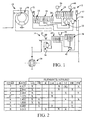
- FIG. 1 is a schematic view of one implementation of a transmission
- FIG. 2 is chart illustrating clutches applied in the transmission of FIG. 1 in the various gears of the transmission;
- FIG. 3 is a schematic view showing the torque flow in the transmission of FIG. 1 when it is in second gear;
- FIG. 4 is a schematic view showing the torque flow in the transmission of FIG. 1 when it is in third gear.
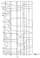
- FIG. 5 is a graph of various parameters and components of the transmission and related components during execution of a downshift.
- FIG. 1 illustrates a six-speed transmission 10 that includes a main gear box 12 and a compounder 14 arranged in series.
- the main gear box 12 is disposed between a torque converter 16 (having a turbine 18) and the compounder 14.
- the compounder 14 in turn, may be disposed between the main box 12 and a differential 20.
- the main gear box 12 may include various friction elements, which in one implementation may include clutches such as an underdrive (UD) clutch 22, overdrive (OD) clutch 24, reverse clutch (R) 26, 2-4 clutch 28, and a low-reverse (L-R) clutch 30, and associated gear sets 32,34.
- UD underdrive
- OD overdrive
- R reverse clutch
- L-R low-reverse
- the clutches and gearsets of the main box 12 provide a 4-speed transmission assembly that may be generally of the type set forth in U.S. Patent No. 4,969,098 , the disclosure of which is incorporated herein by reference in its entirety.
- the compounder 14 may include one additional gear set 36, and associated friction elements such as a LC clutch 38 and a DR clutch 40 with an over-running or freewheel clutch 42. With the addition of the compounder 14, six speed transmission operation can be obtained.
- the construction and arrangemcnt of the transmission may be as set forth in U.S. Publication No. 2006/0142106, published June 29, 2006 , although the method and control for a double swap downshift is as set forth herein.
- a so-called double swap shift is performed to shift the transmission 10 between 2 nd and 3 rd gears.
- an upshift is initiated in the compounder 14 and near the end of the torque phase of that upshift a downshift is initiated in the main box 12.
- the DR clutch 40 is applied (whereupon the freewheel clutch 42 in the compounder 14 will automatically release).
- the 2-4 clutch 28 is released and the L-R clutch 30 is applied in the main box 12 as will be set forth in more derail herein.
- Careful control of this swapshift permits it to be performed smoothly with mininal power loss, bump or other feedback noticeable by the occupants of the vehicle.
- the solenoids that control application or release of the clutches preferably are, but are not limited to, pulse width modulated (PWM) solenoids and hence, the filling and venting of fluid chambers associated with the solenoids are controlled by controlling the duty cycle of the solenoids.
- PWM pulse width modulated
- the instantaneous duty cycle of a given solenoid may be provided or communicated from a table, list or other source of stored data, or it may be a function of closed loop feedback control from various sensors, a combination of both in a given shift sequence or sequences, or otherwise chosen, determined or selected.
- the duty cycle at any given time during a shift may be controlled to achieve a certain target or selected volume of fluid in the clutch, which may be related to the pressure and/or torque capacity of the dutch.
- venting of a release element is not needed since there is an overrunning clutch in the compounder.
- the apply rate for the element being applied is controlled to develop the torque needed to begin the speed change phase the overrunning clutch will automatically disengage. This provides a matched exchange of torque between the release and apply elements without reistance or fight between the release and apply elements and provides a relatively smooth shift.
- the apply element pressure may be controlled to provide desired acceleration of the compounder speed.
- a soft release feature may be used when the releasing clutch is fast vented to a predetermined volume (indicative of torque capacity).
- the slow rate change of the soft release permits good control of the turbine speed after slip occurs in the releasing clutch. After the turbine speed reaches a certain point where the time needed for the turbine to reach a target speed for the selected gear is equal to the time needed to fast fill the applying clutch for the down shift, filling of the applying clutch is initiated.
- FIG. 5 some of the time based events and sequence of a 3rd gear to 2nd gear double swapshift are shown in FIG. 5 .
- the UD and 2-4 clutches 22,28 are applied in the main box 12 and the freewheel clutch 42 is applied in the compounder.
- the L-R and DR clutches 30,40 are applied and the 2-4 and FW clutches 28,42 are released (release of the FW clutch, in this example, may automatically occur upon application of the DR clutch 40 in the compounder 14):
- FIGS. 3 and 4 show torque flow in the transmission in second and third gears, respectively, where applied clutches and active torque flow paths are shown in solid black, and released clutches and inactive flow paths are shown in lighter grey.
- the DR clutch solenoid 46 duty cycle is at 100%, as shown in line 48, for a fast fill and rapid increase in volume of the DR clutch 40 as shown in line 51, and an initial increase in pressure as shown in line 50 to overcome the DR clutch return spring force.
- venting of the release element, the 2-4 clutch 28, is initiated. Venting of the 2-4 clutch 28 may be accomplished with open loop control and may begin after the volume or pressure in the DR clutch 40 reaches some threshold level, or based on some other criteria, including as a function of the time required for the DR clutch 40 to reach required torque capacity to start the speed phase in the compounder (i.e.
- the time required for the DR clutch 40 to reach required torque capacity and the time to release the 2-4 clutch 28 can be coordinated so the slip of the 2-4 clutch occurs within a small time window of when the DR clutch 40 reaches required torque capacity to start the speed phase).
- the torque converter turbine speed and compounder speed may remain relatively constant to this time.
- the torque phase of the upshift in the compounder begins, the fast fill of the DR clutch 40 ends and control of the duty cycle of the DR clutch solenoid 46 begins when the DR clutch fill volume reaches a predetermined or learned volume that corresponds to a predetermined and/or learned pressure just lower than the pressure at which the DR clutch has torque capacity.
- the solenoid duty cycle may be controlled as a function of various parameters including, for example, engine torque, torque converter turbine speed (which may also be called transmission input speed), compounder speed, transmission output speed, and time. As shown in FIG. 1 , the input and output speeds may be measured or sensed by sensors 53,55 respectively, and the compounder speed between the main box 12 and compounder 14 may be sensed at sensor 57.
- the solenoid 46 duty cycle in this time interval should be controlled to gradually reach a learned target volume at t 3 , as may be determined from or learned from a prior shift, as will be set forth below in more detail.
- a soft or slower release of the 2-4 clutch 28 is initiated by moderating the duty cycle of its solenoid 58 (as shown in line 60) to slow the rate at which it is vented and hence, the rate at which its volume (as shown in line 61) and pressure drops (as shown in line 62) so the 2-4 clutch remains just above required torque capacity to hold transmission in gear. Turbine speed and compounder output speed may remain relatively constant.
- the speed phase of both the main box and the compounder begins, and this may occur in two ways.
- the speed phase of the main box and the compounder may occur at generally the same time, or, as set forth below, the speed phase of one of them may trigger the speed phase in the other.
- the manner in which the speed phases are implemented may be chosen, for example, as a function of the torque level, transmission calibration and vehicle speed.
- the DR clutch is controlled (e.g. gradually increased) to a volume below the target volume at which it would require a reduced input torque to initiate the speed phase in the compounder.
- the reduced target volume may be based on the input torque and the desired acceleration of the turbine speed during the speed phase for the downshift in the main box.
- the 2-4 clutch may be softly released until the 2-4 clutch slips, and as a result, the turbine speed increases and the torque to the compounder decreases.
- the pressure in the DR clutch is then sufficient to initiate the speed phase in the compounder due to the decreased torque to the compounder.
- the 2-4 clutch volume is controlled (e.g. gradually decreased) to a volume just above the volume where the 2-4 clutch would slip under the then current torque level in the main box so that the 2-4 clutch does not slip under the then current torque level in the main box.
- the DR clutch volume and hence its torque capacity may be gradually increased to perform a speed change in the compounder, and as a result, the main box input torque increases as the compounder and main box speed decrease.
- the increased input torque causes the 2-4 clutch to slip because the 2-4 clutch was at a pressure just sufficient to prevent slip at the lower input torque, but not sufficient to prevent slip at the increased input torque level. Accordingly, initiation of the speed phase in the main box may trigger the speed phase in the compounder, and vice versa.
- Feedback control of the 2-4 clutch solenoid 58 duty cycle may be initiated when the speed phase is detected.
- Control of the DR clutch solenoid duty cycle can be accomplished by way of open loop or correlated feed forward and feedback control using learned and/or stored data as well as input torque, turbine speed and compounder speed, to bring the compounder speed to its target speed for the selected gear which, in this example, is 2 nd gear. Due to the relatively small ratio change in the compounder, the upshift may finish earlier than the downshift in the main box.
- Feedback control of the 2-4 clutch solenoid 58 duty cycle may be accomplished as a function of feedback from sensors that detect engine torque, turbine speed and compounder speed, by way of examples. As shown in line 60, the duty cycle of the 2-4 clutch solenoid 58 may be increased or decreased to control the pressure in the 2-4 clutch to thereby control the acceleration of the turbine to a desired or predetermined rate of acceleration.
- slip may be detected as a function of the input and output speeds, and the gear ratio. If the input or turbine speed is equal to the compounder speed times the gear ratio in the main box 12, there is no slip in the main box 12. If the turbine speed is greater than the compounder speed times the gear ratio in the main box 12, there is slip in the main box 12.
- the target volume of the DR clutch at which the speed phase of the compounder begins, and/or the soft released start volume at which the soft release or slower venting of the 2-4 clutch begins may be adjusted if slip in the compounder and/or the main box did not occur, in at least one prior double swap downshift, within a threshold or predetermined time.
- the DR clutch is fast filled to a fixed fill volume (shown at t 2 in FIG. 5 ) and then more slowly filled to a learned target volume at which the DR clutch has required torque capacity to make the speed change (shown at t 3 in FIG. 5 ). Then, the length of time from when the DR clutch reaches its target volume until the 2-4 clutch slips can be determined. If that time is longer than desired, the soft release start volume of the 2-4 clutch can be decreased. If that time is negative (2-4 cluth slips earlier), the soft release start volume of the 2-4 clutch can be increased.
- the time from the start of the soft release of the 2-4 clutch from its soft release start volume (shown at t 2 in FIG. 5 ) until the speed phase begins in the main box can be determined. If that time is longer than desired, the soft release start volume of the 2-4 clutch can be decreased to cause the 2-4 clutch to slip sooner during a subsequent double swap downshift. If that time is shorter than desired, the soft release start volume of the 2-4 clutch can be increased to cause the 2-4 clutch to slip later during a subsequent double swap downshift. At the same time, if the time from the 2-4 clutch slip to overrunning clutch slip is longer than expected, the DR clutch limit volume can be increased. If the time is too short and the compounder speed phase is too fast, or the time is negative (overrunning clutch slips earlier), the limit volume of the DR clutch can be decreased.
- the compounder speed may relatively quickly reach its target speed for the selected gear.
- the DR clutch can be ramped up to line pressure, as shown in lines 48, 50 and 51.
- the L-R clutch 30 fast fill ends at t 6 when the volume of that clutch reaches a learned fill volume. For a time thereafter, the pressure in the L-R clutch 30 is maintained by moderating or controlling the duty cycle of its solenoid 66 to hold its volume, which, as shown in line 68, occurs between t 6 and t 7 .
- the turbine speed is above its target speed for the selected gear (2 nd gear in this example), and the fill or apply rate of the L-R clutch 30 is controlled (e.g. gradually increased) to bring the turbine speed to its target speed.
- the 2-4 clutch solenoid 58 duty cycle can be zero or off to permit final venting and release of the 2-4 clutch 28 when the turbine speed is close to or within a threshold of its targeted 2 nd gear speed.
- the 3rd gear to 2nd gear downshift is finished and at t 8 , the turbine reaches its target speed and the L-R clutch 33 is ramped up to line pressure.
- the speed phase in the compounder 14 may be used to trigger the speed phase in the main box 12, or vice versa, and both may begin in a relatively small time window. This permits the positive torque in the upshift to be canceled in whole or in part by the negative torque in the downshift to enable a smooth shift.
- the speed phase of the compounder may be relatively short in the presently preferred implementation and so the compounder is permitted to go to its target speed relatively quickly. At that time the application of the clutch in the compounder can be finished.
- Turbine acceleration may be controlled to bring the turbine to its target speed by control of the duty cycle of the clutch being released in the main box during the double swap shift. When the turbine exceeds its target speed for the selected gear, final application of the clutch being applied in the main box may be initiated.
Description
- This invention relates to a method of controlling a double swap dowshift in a transmission.
- An automatic transmission typically includes an electronically controlled hydraulic system. In such an electro-hydraulic system, hydraulically actuated clutches are actuated to couple and decouple gearsets for changing gear ratios of the transmission. Also, a transmission pump suppiles pressurized hydraulic fluid from a fluid sump to the clutches through fluid passages. Further solenoid actuated valves are placed in fluid communication with the fluid passages upstream of the clutches. Finally, a controller receives vehicle input signals, processes the input signals with shift control algorithms to produce solenoid control output signals, and communicates the output signals to the solenoid valves to control flow of fluid to the clutches.
US2005/0096823 describes·a multiple ratio automatic transmission having a swap shift between at least two transmission ratios.
US2005/0096820 describes an automatic transmission control system with direct electronic swap shift control.
US5,835,875 describes a swap shift control system for a multiple ratio transmission.EP0821,189 is also directed to multiple ratio transmissions with swap-shift controls.
US4,969,098 relates to a method of torque phase shift control for an electronic automatic transmission system.
US2006/0142106 discloses a six-speed transmission incorporating a double swap shift control scheme.
US6,978,201 is directed to a model based kickdown shift method for clutch to clutch shift transmissions with accumulators.
Finally,US2007/0054775 is directed to automatic transmission control systems for vehicles with fluid-actuated clutches having associated accumulators. - It is object of the invention to provide a method of controlling a double swap downshipt, which improves the quality of shift. The object is achieved by the following method.
- A method of controlling a double swap downshift in a transmission having a main gear box and compounder coupled to the main gear box, the method characterized by:
- initiating application of a clutch in the compounder for an upshift in the compounder;
- initiating release of a clutch in the main gear box for a downshift in the main gear box;
- determining a compounder target speed and a target input speed of the main gear box for the selected gear into which the transmission is being shifted;
- controlling the solenoid duty cycle associated with the clutch being applied in the compounder after slip has occurred in the compunder to control the deceleration of the compounder until a compounder speed also defined as a compounder input speed within the threshold value of the compounder target speed and thereafter completing the upshift in the compounder;
- controlling the solenoid duty cycle associated with the clutch being released in the main gear box after slip has occurred in the main gear box to control the acceleration of the main gear box until an input speed of the main gear box is within a threshold value of the target input speed and thereafter completing the downshift in the main gear box.
- The sub-claims disclose further prefered developments of the invention.
- >
- The following detailed description of preferred embodiments and best mode will be set forth with regard to the accompanying drawings in which:
-
FIG. 1 is a schematic view of one implementation of a transmission; -
FIG. 2 is chart illustrating clutches applied in the transmission ofFIG. 1 in the various gears of the transmission; -
FIG. 3 is a schematic view showing the torque flow in the transmission ofFIG. 1 when it is in second gear; -
FIG. 4 is a schematic view showing the torque flow in the transmission ofFIG. 1 when it is in third gear; and -
FIG. 5 is a graph of various parameters and components of the transmission and related components during execution of a downshift. - Referring in more detail to the drawings,
FIG. 1 illustrates a six-speed transmission 10 that includes amain gear box 12 and acompounder 14 arranged in series. In one implementation, themain gear box 12 is disposed between a torque converter 16 (having a turbine 18) and thecompounder 14. Thecompounder 14, in turn, may be disposed between themain box 12 and adifferential 20. Themain gear box 12 may include various friction elements, which in one implementation may include clutches such as an underdrive (UD)clutch 22, overdrive (OD)clutch 24, reverse clutch (R) 26, 2-4clutch 28, and a low-reverse (L-R)clutch 30, and associatedgear sets main box 12 provide a 4-speed transmission assembly that may be generally of the type set forth inU.S. Patent No. 4,969,098 , the disclosure of which is incorporated herein by reference in its entirety. Thecompounder 14 may include oneadditional gear set 36, and associated friction elements such as aLC clutch 38 and aDR clutch 40 with an over-running orfreewheel clutch 42. With the addition of thecompounder 14, six speed transmission operation can be obtained. The construction and arrangemcnt of the transmission may be as set forth inU.S. Publication No. 2006/0142106, published June 29, 2006 , although the method and control for a double swap downshift is as set forth herein. - To accomplish six speed transmission operation, a so-called double swap shift is performed to shift the
transmission 10 between 2nd and 3rd gears. In general terms, during the swap shift an upshift is initiated in thecompounder 14 and near the end of the torque phase of that upshift a downshift is initiated in themain box 12. More specifically, to shift from 3rd to 2nd gear in the implementation of thetransmission 10 illustrated inFIG. 1 theDR clutch 40 is applied (whereupon thefreewheel clutch 42 in thecompounder 14 will automatically release). and near the end of the torque phase of that upshift, the 2-4clutch 28 is released and theL-R clutch 30 is applied in themain box 12 as will be set forth in more derail herein. Careful control of this swapshift permits it to be performed smoothly with mininal power loss, bump or other feedback noticeable by the occupants of the vehicle. - The solenoids that control application or release of the clutches preferably are, but are not limited to, pulse width modulated (PWM) solenoids and hence, the filling and venting of fluid chambers associated with the solenoids are controlled by controlling the duty cycle of the solenoids. The instantaneous duty cycle of a given solenoid may be provided or communicated from a table, list or other source of stored data, or it may be a function of closed loop feedback control from various sensors, a combination of both in a given shift sequence or sequences, or otherwise chosen, determined or selected. The duty cycle at any given time during a shift may be controlled to achieve a certain target or selected volume of fluid in the clutch, which may be related to the pressure and/or torque capacity of the dutch. Such target volume based torque phase control during an upshift is disclosed in
U.S. Patent Application Serial No. 11/222,066, which was filed on September 8, 2005 U.S. Patent No. 6,978,201 - For an upshift in the compounder, venting of a release element is not needed since there is an overrunning clutch in the compounder. When the apply rate for the element being applied is controlled to develop the torque needed to begin the speed change phase the overrunning clutch will automatically disengage. This provides a matched exchange of torque between the release and apply elements without reistance or fight between the release and apply elements and provides a relatively smooth shift. Once the speed change begins the apply element pressure may be controlled to provide desired acceleration of the compounder speed.
- For a downshift in the main box, a soft release feature may be used when the releasing clutch is fast vented to a predetermined volume (indicative of torque capacity). The slow rate change of the soft release permits good control of the turbine speed after slip occurs in the releasing clutch. After the turbine speed reaches a certain point where the time needed for the turbine to reach a target speed for the selected gear is equal to the time needed to fast fill the applying clutch for the down shift, filling of the applying clutch is initiated.
- Turning now to one implementation of a double swap shift, some of the time based events and sequence of a 3rd gear to 2nd gear double swapshift are shown in
FIG. 5 . Prior to initiation of the shift, the UD and 2-4clutches main box 12 and thefreewheel clutch 42 is applied in the compounder. As a result of the shift, the L-R andDR clutches FW clutches DR clutch 40 in the compounder 14):FIGS. 3 and 4 show torque flow in the transmission in second and third gears, respectively, where applied clutches and active torque flow paths are shown in solid black, and released clutches and inactive flow paths are shown in lighter grey. - At to, the start of the downshift sequence, the
DR clutch solenoid 46 duty cycle is at 100%, as shown inline 48, for a fast fill and rapid increase in volume of theDR clutch 40 as shown inline 51, and an initial increase in pressure as shown inline 50 to overcome the DR clutch return spring force. At t1, venting of the release element, the 2-4clutch 28, is initiated. Venting of the 2-4clutch 28 may be accomplished with open loop control and may begin after the volume or pressure in theDR clutch 40 reaches some threshold level, or based on some other criteria, including as a function of the time required for the DR clutch 40 to reach required torque capacity to start the speed phase in the compounder (i.e. the time required for the DR clutch 40 to reach required torque capacity and the time to release the 2-4clutch 28 can be coordinated so the slip of the 2-4 clutch occurs within a small time window of when theDR clutch 40 reaches required torque capacity to start the speed phase). As shown bylines - At t2, the torque phase of the upshift in the compounder begins, the fast fill of the DR clutch 40 ends and control of the duty cycle of the DR
clutch solenoid 46 begins when the DR clutch fill volume reaches a predetermined or learned volume that corresponds to a predetermined and/or learned pressure just lower than the pressure at which the DR clutch has torque capacity. The solenoid duty cycle may be controlled as a function of various parameters including, for example, engine torque, torque converter turbine speed (which may also be called transmission input speed), compounder speed, transmission output speed, and time. As shown inFIG. 1 , the input and output speeds may be measured or sensed bysensors main box 12 andcompounder 14 may be sensed atsensor 57. Thesolenoid 46 duty cycle in this time interval (from t2) should be controlled to gradually reach a learned target volume at t3, as may be determined from or learned from a prior shift, as will be set forth below in more detail. - Also generally at t2, a soft or slower release of the 2-4
clutch 28 is initiated by moderating the duty cycle of its solenoid 58 (as shown in line 60) to slow the rate at which it is vented and hence, the rate at which its volume (as shown in line 61) and pressure drops (as shown in line 62) so the 2-4 clutch remains just above required torque capacity to hold transmission in gear. Turbine speed and compounder output speed may remain relatively constant. - Generally at t3, the speed phase of both the main box and the compounder begins, and this may occur in two ways. The speed phase of the main box and the compounder may occur at generally the same time, or, as set forth below, the speed phase of one of them may trigger the speed phase in the other. The manner in which the speed phases are implemented may be chosen, for example, as a function of the torque level, transmission calibration and vehicle speed.
- According to a first way of initiating the speed phase in the main box and the compounder, the DR clutch is controlled (e.g. gradually increased) to a volume below the target volume at which it would require a reduced input torque to initiate the speed phase in the compounder. The reduced target volume may be based on the input torque and the desired acceleration of the turbine speed during the speed phase for the downshift in the main box. Then, after the fast vent to a predetermined volume, the 2-4 clutch may be softly released until the 2-4 clutch slips, and as a result, the turbine speed increases and the torque to the compounder decreases. The pressure in the DR clutch is then sufficient to initiate the speed phase in the compounder due to the decreased torque to the compounder. According to a second way of initiating the speed phase in the main box and compounder, after fast venting to a predetermined volume, the 2-4 clutch volume is controlled (e.g. gradually decreased) to a volume just above the volume where the 2-4 clutch would slip under the then current torque level in the main box so that the 2-4 clutch does not slip under the then current torque level in the main box. Then, the DR clutch volume and hence its torque capacity may be gradually increased to perform a speed change in the compounder, and as a result, the main box input torque increases as the compounder and main box speed decrease. The increased input torque causes the 2-4 clutch to slip because the 2-4 clutch was at a pressure just sufficient to prevent slip at the lower input torque, but not sufficient to prevent slip at the increased input torque level. Accordingly, initiation of the speed phase in the main box may trigger the speed phase in the compounder, and vice versa.
- Feedback control of the 2-4
clutch solenoid 58 duty cycle may be initiated when the speed phase is detected. Control of the DR clutch solenoid duty cycle can be accomplished by way of open loop or correlated feed forward and feedback control using learned and/or stored data as well as input torque, turbine speed and compounder speed, to bring the compounder speed to its target speed for the selected gear which, in this example, is 2nd gear. Due to the relatively small ratio change in the compounder, the upshift may finish earlier than the downshift in the main box. Feedback control of the 2-4clutch solenoid 58 duty cycle may be accomplished as a function of feedback from sensors that detect engine torque, turbine speed and compounder speed, by way of examples. As shown inline 60, the duty cycle of the 2-4clutch solenoid 58 may be increased or decreased to control the pressure in the 2-4 clutch to thereby control the acceleration of the turbine to a desired or predetermined rate of acceleration. - As is known in the art, slip may be detected as a function of the input and output speeds, and the gear ratio. If the input or turbine speed is equal to the compounder speed times the gear ratio in the
main box 12, there is no slip in themain box 12. If the turbine speed is greater than the compounder speed times the gear ratio in themain box 12, there is slip in themain box 12. The target volume of the DR clutch at which the speed phase of the compounder begins, and/or the soft released start volume at which the soft release or slower venting of the 2-4 clutch begins may be adjusted if slip in the compounder and/or the main box did not occur, in at least one prior double swap downshift, within a threshold or predetermined time. For example, when the speed phase in the compounder is used to trigger the speed phase in the main box, the DR clutch is fast filled to a fixed fill volume (shown at t2 inFIG. 5 ) and then more slowly filled to a learned target volume at which the DR clutch has required torque capacity to make the speed change (shown at t3 inFIG. 5 ). Then, the length of time from when the DR clutch reaches its target volume until the 2-4 clutch slips can be determined. If that time is longer than desired, the soft release start volume of the 2-4 clutch can be decreased. If that time is negative (2-4 cluth slips earlier), the soft release start volume of the 2-4 clutch can be increased. When the speed phase in the main box is used to trigger the speed phase in the compounder, the time from the start of the soft release of the 2-4 clutch from its soft release start volume (shown at t2 inFIG. 5 ) until the speed phase begins in the main box can be determined. If that time is longer than desired, the soft release start volume of the 2-4 clutch can be decreased to cause the 2-4 clutch to slip sooner during a subsequent double swap downshift. If that time is shorter than desired, the soft release start volume of the 2-4 clutch can be increased to cause the 2-4 clutch to slip later during a subsequent double swap downshift. At the same time, if the time from the 2-4 clutch slip to overrunning clutch slip is longer than expected, the DR clutch limit volume can be increased. If the time is too short and the compounder speed phase is too fast, or the time is negative (overrunning clutch slips earlier), the limit volume of the DR clutch can be decreased. - As shown in line 63, rapid or fast fill of the L-R clutch 30 volume is initiated when the time to fill the L-R clutch 30 is less than or equal to the time to increase the turbine speed from its current speed to a target speed for the selected gear. Initiation of the L-R clutch 30 fast fill is shown at t4 in
FIG. 5 . - At t5, because the
compounder 14 has a small ratio to change, the compounder speed may relatively quickly reach its target speed for the selected gear. When the compounder reaches its target speed, the DR clutch can be ramped up to line pressure, as shown inlines - The L-R clutch 30 fast fill ends at t6 when the volume of that clutch reaches a learned fill volume. For a time thereafter, the pressure in the
L-R clutch 30 is maintained by moderating or controlling the duty cycle of itssolenoid 66 to hold its volume, which, as shown inline 68, occurs between t6 and t7. - At t7, the turbine speed is above its target speed for the selected gear (2nd gear in this example), and the fill or apply rate of the L-R clutch 30 is controlled (e.g. gradually increased) to bring the turbine speed to its target speed. At this time, the 2-4
clutch solenoid 58 duty cycle can be zero or off to permit final venting and release of the 2-4clutch 28 when the turbine speed is close to or within a threshold of its targeted 2nd gear speed. Preferably soon thereafter, the 3rd gear to 2nd gear downshift is finished and at t8, the turbine reaches its target speed and the L-R clutch 33 is ramped up to line pressure. - In general terms and according to the implementation discussed above, the speed phase in the
compounder 14 may be used to trigger the speed phase in themain box 12, or vice versa, and both may begin in a relatively small time window. This permits the positive torque in the upshift to be canceled in whole or in part by the negative torque in the downshift to enable a smooth shift. The speed phase of the compounder may be relatively short in the presently preferred implementation and so the compounder is permitted to go to its target speed relatively quickly. At that time the application of the clutch in the compounder can be finished. Turbine acceleration may be controlled to bring the turbine to its target speed by control of the duty cycle of the clutch being released in the main box during the double swap shift. When the turbine exceeds its target speed for the selected gear, final application of the clutch being applied in the main box may be initiated. - While certain preferred embodiments have been shown and described, persons of ordinary skill in this art will readily recognize that the preceding description has been set forth in terms of description rather than limitation. For example, while the term `clutch' has been used throughout the description, that term may be interchangeable with the term 'friction element' or other corresponding structure. Accordingly, the invention should not be limited by a particular definition of the term `clutch' or by any particular construction of a `clutch' used by the assignee hereof or otherwise. The invention is defined by the following claims
Claims (5)
- A method of controlling a double swap downshift in a transmission (10) having a main gear box (12) and compounder (14) coupled to the main gear box (12), the method comprises:initiating application of a clutch (40) in the compounder (14) for an upshift in the compounder (14);initiating release of a clutch (28) in the main gear box (12) for a downshift in the main gear box (12);determining a compounder target speed and a target input speed of the main gear box (12) for the selected gear into which the transmission is being shifted;controlling the solenoid (46) duty cycle associated with the clutch being applied in the compounder (14) after slip has occurred in the compunder (14) to control the deceleration of the compounder (14) until a compounder speed also defined as a compounder input speed within the threshold value of the compounder target speed and thereafter completing the upshift in the compounder (14);controlling the solenoid (58) duty cycle associated with the clutch being released in the main gear box (12) after slip has occurred in the main gear box (12) to control the acceleration of the main gear box (12) until an input speed of the main gear box (12) is within a threshold value of the target input speed and thereafter completing the downshift in the main gear box (12).
- The method of claim 1, wherein the upshift is initiated by controlling the duty cycle of a solenoid associated with the clutch being applied in the compounder (14) to increase the fluid volume in the clutch being applied, and wherein the fluid volume is increased at a first rate until a desired fill volume is reached, and thereafter is increased at a second rate until a target volume is reached.
- The method of claim 2 which also comprises adjusting the target volume if, in at least one prior double swap downshift, slip in the main gear box (12) occurred at a time different than a predetermined time.
- The method of claim 1, wherein initiating release of a clutch in the main gear box (12) for a downshift in the main gear box (12) includes venting a clutch to be released in the main gear box (12) at a first rate until a target volume is reached and venting the same clutch at a second rate after the target volume is reached.
- The method of claim 4 which also comprises adjusting the target volume if, in at lest one prior double swap downshift, slip in at least one of the main gear box (12) or the compounder (14) occurred at a time different than a predetermined time.
Applications Claiming Priority (1)
| Application Number | Priority Date | Filing Date | Title |
|---|---|---|---|
| US11/536,734 US7608013B2 (en) | 2006-09-29 | 2006-09-29 | Transmission downshift control method |
Publications (3)
| Publication Number | Publication Date |
|---|---|
| EP1906061A2 EP1906061A2 (en) | 2008-04-02 |
| EP1906061A3 EP1906061A3 (en) | 2010-07-07 |
| EP1906061B1 true EP1906061B1 (en) | 2012-12-05 |
Family
ID=39004788
Family Applications (1)
| Application Number | Title | Priority Date | Filing Date |
|---|---|---|---|
| EP07018838A Active EP1906061B1 (en) | 2006-09-29 | 2007-09-25 | Transmission downshift control method |
Country Status (2)
| Country | Link |
|---|---|
| US (1) | US7608013B2 (en) |
| EP (1) | EP1906061B1 (en) |
Families Citing this family (10)
| Publication number | Priority date | Publication date | Assignee | Title |
|---|---|---|---|---|
| US7632215B2 (en) * | 2006-12-05 | 2009-12-15 | Chrysler Group Llc | Transmission downshift swap-shift control |
| JP4360406B2 (en) * | 2007-01-10 | 2009-11-11 | トヨタ自動車株式会社 | Powertrain control device, control method, program for realizing the method, and recording medium recording the program |
| FR2911656B1 (en) * | 2007-01-19 | 2009-10-02 | Renault Sas | METHOD OF CONTROLLING THE SLIDING OF THE DIRECT TAPPING CLUTCH OF A TORQUE CONVERTER |
| US8066620B2 (en) * | 2009-05-19 | 2011-11-29 | GM Global Technology Operations LLC | Method of clutch actuation for hybrid transmissions |
| EP2638311B1 (en) | 2010-11-12 | 2018-09-05 | Allison Transmission, Inc. | Double transition shift control in an automatic powershifting transmission |
| US8744705B2 (en) * | 2012-03-15 | 2014-06-03 | GM Global Technology Operations LLC | System and method for determining clutch gains in a transmission during a power downshift |
| US8974345B2 (en) | 2012-08-17 | 2015-03-10 | Chrysler Group Llc | Double swap kickdown shift control |
| JP5928530B2 (en) * | 2014-06-18 | 2016-06-01 | トヨタ自動車株式会社 | Hydraulic transmission control amount generation device for automatic transmission and control device for automatic transmission |
| KR101826547B1 (en) * | 2015-12-14 | 2018-02-07 | 현대자동차 주식회사 | Apparatus for controlling for automatic transmission and method thereof |
| CN115059755B (en) * | 2022-07-18 | 2023-04-28 | 山东临工工程机械有限公司 | Vehicle control method and vehicle |
Family Cites Families (18)
| Publication number | Priority date | Publication date | Assignee | Title |
|---|---|---|---|---|
| US4481836A (en) * | 1982-02-12 | 1984-11-13 | Eaton Corporation | Multiple identical countershaft powershift transmission |
| US5029583A (en) * | 1986-07-22 | 1991-07-09 | Personal Diagnostics, Inc. | Optical analyzer |
| US4969098A (en) * | 1988-04-29 | 1990-11-06 | Chrysler Corporation | Method of torque phase shift control for an electronic automatic transmission system |
| US5835875A (en) * | 1995-10-27 | 1998-11-10 | Ford Global Technologies, Inc. | Swap-shift control system for a multiple ratio transmission |
| US5809442A (en) * | 1995-10-27 | 1998-09-15 | Ford Global Technologies, Inc. | Multiple ratio transmission having swap-shift controls with optimum ratio upshifts |
| US5642283A (en) * | 1995-10-27 | 1997-06-24 | Ford Motor Company | Multiple ratio transmission with swap-shift controls |
| JP3296173B2 (en) * | 1995-12-28 | 2002-06-24 | アイシン・エィ・ダブリュ株式会社 | Control device for automatic transmission |
| US5830219A (en) * | 1997-02-24 | 1998-11-03 | Trex Medical Corporation | Apparatus for holding and driving a surgical cutting device using stereotactic mammography guidance |
| US6292731B1 (en) * | 1998-07-27 | 2001-09-18 | Ford Global Technologies, Inc. | Automatic shift control system for an automatic transmission including a select-shift manual control |
| US6200242B1 (en) * | 1999-12-10 | 2001-03-13 | General Motors Corporation | Powertrain with a multi-speed transmission |
| US6301538B1 (en) * | 2000-06-07 | 2001-10-09 | Ford Global Technologies, Inc. | Swap shift multiple-ratio automatic transmission |
| US6370463B1 (en) * | 2001-11-01 | 2002-04-09 | Ford Global Technologies, Inc. | Strategy for controlling ratio changes in a swap-shift automatic transmission |
| US6577939B1 (en) * | 2002-05-20 | 2003-06-10 | Ford Global Technologies, Llc | Pressure control system and control method for a multiple-ratio transmission with pre-staged ratio shifts |
| US7107135B2 (en) * | 2003-10-31 | 2006-09-12 | Ford Global Technologies, Llc | Auxiliary gearset shift progression command generator for a swap-shift automatic transmission |
| US6961646B2 (en) * | 2003-10-31 | 2005-11-01 | Ford Global Technologies, Llc | Automatic transmission control system with direct electronic swap-shift control |
| US6978201B1 (en) * | 2004-12-22 | 2005-12-20 | Daimlerchrysler Corporation | Model based kickdown shift method for clutch to clutch shift transmissions with accumulators |
| US7179189B2 (en) * | 2004-12-23 | 2007-02-20 | Daimlerchrysler Corporation | Swap shift control |
| US7292922B2 (en) * | 2005-09-08 | 2007-11-06 | Chrysler Llc | Target volume based torque phase control during upshift |
-
2006
- 2006-09-29 US US11/536,734 patent/US7608013B2/en active Active
-
2007
- 2007-09-25 EP EP07018838A patent/EP1906061B1/en active Active
Also Published As
| Publication number | Publication date |
|---|---|
| EP1906061A2 (en) | 2008-04-02 |
| EP1906061A3 (en) | 2010-07-07 |
| US7608013B2 (en) | 2009-10-27 |
| US20080081736A1 (en) | 2008-04-03 |
Similar Documents
| Publication | Publication Date | Title |
|---|---|---|
| EP1906061B1 (en) | Transmission downshift control method | |
| EP1096178B1 (en) | Shift control apparatus and method for an automatic transmission | |
| US7351183B2 (en) | Ratio shift control for a multiple ratio automatic transmission | |
| US6832976B2 (en) | Shift control apparatus for automatic transmission | |
| EP1906060B1 (en) | Transmission upshift control method | |
| US6626786B2 (en) | Speed shift control apparatus of automatic transmission | |
| US6319172B1 (en) | Off-going clutch control for upshifting of an automatic transmission | |
| US6503165B1 (en) | Hydraulic control device for automatic transmission | |
| EP2136108A2 (en) | Automatic transmission control apparatus and method | |
| JPH04312260A (en) | Method of operating automatic transmission | |
| US20020147071A1 (en) | Control apparatus for automatic transmission | |
| US6955629B2 (en) | Shift control apparatus for an automatic transmission | |
| US5797821A (en) | Shift control apparatus for automatic transmission | |
| EP1249644B1 (en) | Speed-change control apparatus for automatic transmission | |
| EP2136107A2 (en) | Control apparatus for automatic transmission | |
| US5655993A (en) | Shift control apparatus for an automatic transmission | |
| JP2003139236A (en) | Lock-up controller for automatic transmission | |
| JPH04312259A (en) | Method of operating automatic transmission | |
| JP3130615B2 (en) | Servo hydraulic controller for automatic transmission | |
| EP0770801A2 (en) | Oil pressure control system for automatic vehicle transmission | |
| US6638196B2 (en) | Shift control apparatus of automatic transmissions | |
| US7632215B2 (en) | Transmission downshift swap-shift control | |
| JP3869642B2 (en) | Target hydraulic pressure judgment device for automatic transmission | |
| JP3085028B2 (en) | Transmission control device for automatic transmission | |
| JP3938840B2 (en) | Control device for prohibiting re-transmission of automatic transmission |
Legal Events
| Date | Code | Title | Description |
|---|---|---|---|
| PUAI | Public reference made under article 153(3) epc to a published international application that has entered the european phase |
Free format text: ORIGINAL CODE: 0009012 |
|
| AK | Designated contracting states |
Kind code of ref document: A2 Designated state(s): AT BE BG CH CY CZ DE DK EE ES FI FR GB GR HU IE IS IT LI LT LU LV MC MT NL PL PT RO SE SI SK TR |
|
| AX | Request for extension of the european patent |
Extension state: AL BA HR MK YU |
|
| RAP1 | Party data changed (applicant data changed or rights of an application transferred) |
Owner name: CHRYSLER GROUP LLC |
|
| PUAL | Search report despatched |
Free format text: ORIGINAL CODE: 0009013 |
|
| AK | Designated contracting states |
Kind code of ref document: A3 Designated state(s): AT BE BG CH CY CZ DE DK EE ES FI FR GB GR HU IE IS IT LI LT LU LV MC MT NL PL PT RO SE SI SK TR |
|
| AX | Request for extension of the european patent |
Extension state: AL BA HR MK RS |
|
| RIC1 | Information provided on ipc code assigned before grant |
Ipc: F16H 61/04 20060101ALI20100528BHEP Ipc: F16H 61/02 20060101AFI20080213BHEP |
|
| 17P | Request for examination filed |
Effective date: 20110107 |
|
| AKX | Designation fees paid |
Designated state(s): DE FR GB |
|
| 17Q | First examination report despatched |
Effective date: 20110525 |
|
| GRAP | Despatch of communication of intention to grant a patent |
Free format text: ORIGINAL CODE: EPIDOSNIGR1 |
|
| GRAS | Grant fee paid |
Free format text: ORIGINAL CODE: EPIDOSNIGR3 |
|
| GRAA | (expected) grant |
Free format text: ORIGINAL CODE: 0009210 |
|
| AK | Designated contracting states |
Kind code of ref document: B1 Designated state(s): DE FR GB |
|
| REG | Reference to a national code |
Ref country code: GB Ref legal event code: FG4D |
|
| REG | Reference to a national code |
Ref country code: DE Ref legal event code: R096 Ref document number: 602007027084 Country of ref document: DE Effective date: 20130131 |
|
| PLBE | No opposition filed within time limit |
Free format text: ORIGINAL CODE: 0009261 |
|
| STAA | Information on the status of an ep patent application or granted ep patent |
Free format text: STATUS: NO OPPOSITION FILED WITHIN TIME LIMIT |
|
| 26N | No opposition filed |
Effective date: 20130906 |
|
| REG | Reference to a national code |
Ref country code: DE Ref legal event code: R097 Ref document number: 602007027084 Country of ref document: DE Effective date: 20130906 |
|
| REG | Reference to a national code |
Ref country code: FR Ref legal event code: PLFP Year of fee payment: 10 |
|
| REG | Reference to a national code |
Ref country code: FR Ref legal event code: PLFP Year of fee payment: 11 |
|
| REG | Reference to a national code |
Ref country code: FR Ref legal event code: PLFP Year of fee payment: 12 |
|
| PGFP | Annual fee paid to national office [announced via postgrant information from national office to epo] |
Ref country code: FR Payment date: 20210927 Year of fee payment: 15 |
|
| PGFP | Annual fee paid to national office [announced via postgrant information from national office to epo] |
Ref country code: GB Payment date: 20220927 Year of fee payment: 16 Ref country code: DE Payment date: 20220928 Year of fee payment: 16 |
|
| PG25 | Lapsed in a contracting state [announced via postgrant information from national office to epo] |
Ref country code: FR Free format text: LAPSE BECAUSE OF NON-PAYMENT OF DUE FEES Effective date: 20220930 |