EP0821189A2 - Multiple ratio transmission with swap-shift controls - Google Patents
Multiple ratio transmission with swap-shift controls Download PDFInfo
- Publication number
- EP0821189A2 EP0821189A2 EP97305448A EP97305448A EP0821189A2 EP 0821189 A2 EP0821189 A2 EP 0821189A2 EP 97305448 A EP97305448 A EP 97305448A EP 97305448 A EP97305448 A EP 97305448A EP 0821189 A2 EP0821189 A2 EP 0821189A2
- Authority
- EP
- European Patent Office
- Prior art keywords
- pressure
- gear unit
- brake
- control
- speed
- Prior art date
- Legal status (The legal status is an assumption and is not a legal conclusion. Google has not performed a legal analysis and makes no representation as to the accuracy of the status listed.)
- Granted
Links
Images


Classifications
-
- F—MECHANICAL ENGINEERING; LIGHTING; HEATING; WEAPONS; BLASTING
- F16—ENGINEERING ELEMENTS AND UNITS; GENERAL MEASURES FOR PRODUCING AND MAINTAINING EFFECTIVE FUNCTIONING OF MACHINES OR INSTALLATIONS; THERMAL INSULATION IN GENERAL
- F16H—GEARING
- F16H61/00—Control functions within control units of change-speed- or reversing-gearings for conveying rotary motion ; Control of exclusively fluid gearing, friction gearing, gearings with endless flexible members or other particular types of gearing
- F16H61/70—Control functions within control units of change-speed- or reversing-gearings for conveying rotary motion ; Control of exclusively fluid gearing, friction gearing, gearings with endless flexible members or other particular types of gearing specially adapted for change-speed gearing in group arrangement, i.e. with separate change-speed gear trains arranged in series, e.g. range or overdrive-type gearing arrangements
- F16H61/702—Control functions within control units of change-speed- or reversing-gearings for conveying rotary motion ; Control of exclusively fluid gearing, friction gearing, gearings with endless flexible members or other particular types of gearing specially adapted for change-speed gearing in group arrangement, i.e. with separate change-speed gear trains arranged in series, e.g. range or overdrive-type gearing arrangements using electric or electrohydraulic control means
-
- F—MECHANICAL ENGINEERING; LIGHTING; HEATING; WEAPONS; BLASTING
- F16—ENGINEERING ELEMENTS AND UNITS; GENERAL MEASURES FOR PRODUCING AND MAINTAINING EFFECTIVE FUNCTIONING OF MACHINES OR INSTALLATIONS; THERMAL INSULATION IN GENERAL
- F16H—GEARING
- F16H61/00—Control functions within control units of change-speed- or reversing-gearings for conveying rotary motion ; Control of exclusively fluid gearing, friction gearing, gearings with endless flexible members or other particular types of gearing
- F16H61/04—Smoothing ratio shift
- F16H61/06—Smoothing ratio shift by controlling rate of change of fluid pressure
- F16H61/061—Smoothing ratio shift by controlling rate of change of fluid pressure using electric control means
-
- F—MECHANICAL ENGINEERING; LIGHTING; HEATING; WEAPONS; BLASTING
- F16—ENGINEERING ELEMENTS AND UNITS; GENERAL MEASURES FOR PRODUCING AND MAINTAINING EFFECTIVE FUNCTIONING OF MACHINES OR INSTALLATIONS; THERMAL INSULATION IN GENERAL
- F16H—GEARING
- F16H59/00—Control inputs to control units of change-speed-, or reversing-gearings for conveying rotary motion
- F16H59/36—Inputs being a function of speed
- F16H59/38—Inputs being a function of speed of gearing elements
- F16H2059/385—Turbine speed
-
- F—MECHANICAL ENGINEERING; LIGHTING; HEATING; WEAPONS; BLASTING
- F16—ENGINEERING ELEMENTS AND UNITS; GENERAL MEASURES FOR PRODUCING AND MAINTAINING EFFECTIVE FUNCTIONING OF MACHINES OR INSTALLATIONS; THERMAL INSULATION IN GENERAL
- F16H—GEARING
- F16H61/00—Control functions within control units of change-speed- or reversing-gearings for conveying rotary motion ; Control of exclusively fluid gearing, friction gearing, gearings with endless flexible members or other particular types of gearing
- F16H2061/0075—Control functions within control units of change-speed- or reversing-gearings for conveying rotary motion ; Control of exclusively fluid gearing, friction gearing, gearings with endless flexible members or other particular types of gearing characterised by a particular control method
- F16H2061/0078—Linear control, e.g. PID, state feedback or Kalman
-
- F—MECHANICAL ENGINEERING; LIGHTING; HEATING; WEAPONS; BLASTING
- F16—ENGINEERING ELEMENTS AND UNITS; GENERAL MEASURES FOR PRODUCING AND MAINTAINING EFFECTIVE FUNCTIONING OF MACHINES OR INSTALLATIONS; THERMAL INSULATION IN GENERAL
- F16H—GEARING
- F16H61/00—Control functions within control units of change-speed- or reversing-gearings for conveying rotary motion ; Control of exclusively fluid gearing, friction gearing, gearings with endless flexible members or other particular types of gearing
- F16H61/02—Control functions within control units of change-speed- or reversing-gearings for conveying rotary motion ; Control of exclusively fluid gearing, friction gearing, gearings with endless flexible members or other particular types of gearing characterised by the signals used
- F16H61/0202—Control functions within control units of change-speed- or reversing-gearings for conveying rotary motion ; Control of exclusively fluid gearing, friction gearing, gearings with endless flexible members or other particular types of gearing characterised by the signals used the signals being electric
- F16H61/0204—Control functions within control units of change-speed- or reversing-gearings for conveying rotary motion ; Control of exclusively fluid gearing, friction gearing, gearings with endless flexible members or other particular types of gearing characterised by the signals used the signals being electric for gearshift control, e.g. control functions for performing shifting or generation of shift signal
- F16H61/0206—Layout of electro-hydraulic control circuits, e.g. arrangement of valves
- F16H2061/0209—Layout of electro-hydraulic control circuits, e.g. arrangement of valves with independent solenoid valves modulating the pressure individually for each clutch or brake
-
- F—MECHANICAL ENGINEERING; LIGHTING; HEATING; WEAPONS; BLASTING
- F16—ENGINEERING ELEMENTS AND UNITS; GENERAL MEASURES FOR PRODUCING AND MAINTAINING EFFECTIVE FUNCTIONING OF MACHINES OR INSTALLATIONS; THERMAL INSULATION IN GENERAL
- F16H—GEARING
- F16H61/00—Control functions within control units of change-speed- or reversing-gearings for conveying rotary motion ; Control of exclusively fluid gearing, friction gearing, gearings with endless flexible members or other particular types of gearing
- F16H61/02—Control functions within control units of change-speed- or reversing-gearings for conveying rotary motion ; Control of exclusively fluid gearing, friction gearing, gearings with endless flexible members or other particular types of gearing characterised by the signals used
- F16H61/0202—Control functions within control units of change-speed- or reversing-gearings for conveying rotary motion ; Control of exclusively fluid gearing, friction gearing, gearings with endless flexible members or other particular types of gearing characterised by the signals used the signals being electric
- F16H61/0251—Elements specially adapted for electric control units, e.g. valves for converting electrical signals to fluid signals
- F16H2061/0255—Solenoid valve using PWM or duty-cycle control
-
- F—MECHANICAL ENGINEERING; LIGHTING; HEATING; WEAPONS; BLASTING
- F16—ENGINEERING ELEMENTS AND UNITS; GENERAL MEASURES FOR PRODUCING AND MAINTAINING EFFECTIVE FUNCTIONING OF MACHINES OR INSTALLATIONS; THERMAL INSULATION IN GENERAL
- F16H—GEARING
- F16H61/00—Control functions within control units of change-speed- or reversing-gearings for conveying rotary motion ; Control of exclusively fluid gearing, friction gearing, gearings with endless flexible members or other particular types of gearing
- F16H61/02—Control functions within control units of change-speed- or reversing-gearings for conveying rotary motion ; Control of exclusively fluid gearing, friction gearing, gearings with endless flexible members or other particular types of gearing characterised by the signals used
- F16H61/0202—Control functions within control units of change-speed- or reversing-gearings for conveying rotary motion ; Control of exclusively fluid gearing, friction gearing, gearings with endless flexible members or other particular types of gearing characterised by the signals used the signals being electric
- F16H61/0251—Elements specially adapted for electric control units, e.g. valves for converting electrical signals to fluid signals
- F16H2061/0258—Proportional solenoid valve
-
- F—MECHANICAL ENGINEERING; LIGHTING; HEATING; WEAPONS; BLASTING
- F16—ENGINEERING ELEMENTS AND UNITS; GENERAL MEASURES FOR PRODUCING AND MAINTAINING EFFECTIVE FUNCTIONING OF MACHINES OR INSTALLATIONS; THERMAL INSULATION IN GENERAL
- F16H—GEARING
- F16H61/00—Control functions within control units of change-speed- or reversing-gearings for conveying rotary motion ; Control of exclusively fluid gearing, friction gearing, gearings with endless flexible members or other particular types of gearing
- F16H61/04—Smoothing ratio shift
- F16H2061/0451—Smoothing ratio shift during swap-shifts, i.e. gear shifts between different planetary units, e.g. with double transitions shift involving three or more friction members
-
- F—MECHANICAL ENGINEERING; LIGHTING; HEATING; WEAPONS; BLASTING
- F16—ENGINEERING ELEMENTS AND UNITS; GENERAL MEASURES FOR PRODUCING AND MAINTAINING EFFECTIVE FUNCTIONING OF MACHINES OR INSTALLATIONS; THERMAL INSULATION IN GENERAL
- F16H—GEARING
- F16H61/00—Control functions within control units of change-speed- or reversing-gearings for conveying rotary motion ; Control of exclusively fluid gearing, friction gearing, gearings with endless flexible members or other particular types of gearing
- F16H61/04—Smoothing ratio shift
- F16H2061/0466—Smoothing shift shock by apply or release of band brake servos, e.g. overlap control of band brake and a clutch or vice versa
-
- F—MECHANICAL ENGINEERING; LIGHTING; HEATING; WEAPONS; BLASTING
- F16—ENGINEERING ELEMENTS AND UNITS; GENERAL MEASURES FOR PRODUCING AND MAINTAINING EFFECTIVE FUNCTIONING OF MACHINES OR INSTALLATIONS; THERMAL INSULATION IN GENERAL
- F16H—GEARING
- F16H2306/00—Shifting
- F16H2306/14—Skipping gear shift
-
- F—MECHANICAL ENGINEERING; LIGHTING; HEATING; WEAPONS; BLASTING
- F16—ENGINEERING ELEMENTS AND UNITS; GENERAL MEASURES FOR PRODUCING AND MAINTAINING EFFECTIVE FUNCTIONING OF MACHINES OR INSTALLATIONS; THERMAL INSULATION IN GENERAL
- F16H—GEARING
- F16H2306/00—Shifting
- F16H2306/40—Shifting activities
- F16H2306/44—Removing torque from current gears
-
- F—MECHANICAL ENGINEERING; LIGHTING; HEATING; WEAPONS; BLASTING
- F16—ENGINEERING ELEMENTS AND UNITS; GENERAL MEASURES FOR PRODUCING AND MAINTAINING EFFECTIVE FUNCTIONING OF MACHINES OR INSTALLATIONS; THERMAL INSULATION IN GENERAL
- F16H—GEARING
- F16H2306/00—Shifting
- F16H2306/40—Shifting activities
- F16H2306/52—Applying torque to new gears
-
- F—MECHANICAL ENGINEERING; LIGHTING; HEATING; WEAPONS; BLASTING
- F16—ENGINEERING ELEMENTS AND UNITS; GENERAL MEASURES FOR PRODUCING AND MAINTAINING EFFECTIVE FUNCTIONING OF MACHINES OR INSTALLATIONS; THERMAL INSULATION IN GENERAL
- F16H—GEARING
- F16H59/00—Control inputs to control units of change-speed-, or reversing-gearings for conveying rotary motion
- F16H59/36—Inputs being a function of speed
- F16H59/38—Inputs being a function of speed of gearing elements
- F16H59/40—Output shaft speed
-
- F—MECHANICAL ENGINEERING; LIGHTING; HEATING; WEAPONS; BLASTING
- F16—ENGINEERING ELEMENTS AND UNITS; GENERAL MEASURES FOR PRODUCING AND MAINTAINING EFFECTIVE FUNCTIONING OF MACHINES OR INSTALLATIONS; THERMAL INSULATION IN GENERAL
- F16H—GEARING
- F16H59/00—Control inputs to control units of change-speed-, or reversing-gearings for conveying rotary motion
- F16H59/36—Inputs being a function of speed
- F16H59/38—Inputs being a function of speed of gearing elements
- F16H59/42—Input shaft speed
-
- F—MECHANICAL ENGINEERING; LIGHTING; HEATING; WEAPONS; BLASTING
- F16—ENGINEERING ELEMENTS AND UNITS; GENERAL MEASURES FOR PRODUCING AND MAINTAINING EFFECTIVE FUNCTIONING OF MACHINES OR INSTALLATIONS; THERMAL INSULATION IN GENERAL
- F16H—GEARING
- F16H59/00—Control inputs to control units of change-speed-, or reversing-gearings for conveying rotary motion
- F16H59/36—Inputs being a function of speed
- F16H59/44—Inputs being a function of speed dependent on machine speed of the machine, e.g. the vehicle
-
- F—MECHANICAL ENGINEERING; LIGHTING; HEATING; WEAPONS; BLASTING
- F16—ENGINEERING ELEMENTS AND UNITS; GENERAL MEASURES FOR PRODUCING AND MAINTAINING EFFECTIVE FUNCTIONING OF MACHINES OR INSTALLATIONS; THERMAL INSULATION IN GENERAL
- F16H—GEARING
- F16H61/00—Control functions within control units of change-speed- or reversing-gearings for conveying rotary motion ; Control of exclusively fluid gearing, friction gearing, gearings with endless flexible members or other particular types of gearing
- F16H61/04—Smoothing ratio shift
- F16H61/08—Timing control
-
- F—MECHANICAL ENGINEERING; LIGHTING; HEATING; WEAPONS; BLASTING
- F16—ENGINEERING ELEMENTS AND UNITS; GENERAL MEASURES FOR PRODUCING AND MAINTAINING EFFECTIVE FUNCTIONING OF MACHINES OR INSTALLATIONS; THERMAL INSULATION IN GENERAL
- F16H—GEARING
- F16H61/00—Control functions within control units of change-speed- or reversing-gearings for conveying rotary motion ; Control of exclusively fluid gearing, friction gearing, gearings with endless flexible members or other particular types of gearing
- F16H61/68—Control functions within control units of change-speed- or reversing-gearings for conveying rotary motion ; Control of exclusively fluid gearing, friction gearing, gearings with endless flexible members or other particular types of gearing specially adapted for stepped gearings
- F16H61/684—Control functions within control units of change-speed- or reversing-gearings for conveying rotary motion ; Control of exclusively fluid gearing, friction gearing, gearings with endless flexible members or other particular types of gearing specially adapted for stepped gearings without interruption of drive
- F16H61/686—Control functions within control units of change-speed- or reversing-gearings for conveying rotary motion ; Control of exclusively fluid gearing, friction gearing, gearings with endless flexible members or other particular types of gearing specially adapted for stepped gearings without interruption of drive with orbital gears
-
- F—MECHANICAL ENGINEERING; LIGHTING; HEATING; WEAPONS; BLASTING
- F16—ENGINEERING ELEMENTS AND UNITS; GENERAL MEASURES FOR PRODUCING AND MAINTAINING EFFECTIVE FUNCTIONING OF MACHINES OR INSTALLATIONS; THERMAL INSULATION IN GENERAL
- F16H—GEARING
- F16H63/00—Control outputs from the control unit to change-speed- or reversing-gearings for conveying rotary motion or to other devices than the final output mechanism
- F16H63/02—Final output mechanisms therefor; Actuating means for the final output mechanisms
- F16H63/30—Constructional features of the final output mechanisms
- F16H63/3003—Band brake actuating mechanisms
Definitions
- An automatic transmission for an automotive vehicle comprising separate planetary gear units and controls for effecting upshifting one gear unit while downshifting the other gear unit in timed relationship.
- U.S. Patent application Serial No. 08/323,464, filed October 14, 1994 discloses a four-speed ratio transmission for use in an automotive vehicle having an internal combustion engine. That transmission is disclosed also in U.S. Patent No. 4,966,050.
- the transmission disclosed in U.S.-A- 4966050 has four forward driving ratios.
- the torque flow paths for the transmission gearing are defined by a Simpson gearset and a simple planetary gearset, both gearsets being situated between the turbine of a torque converter and the torque output shaft.
- the Simpson gearset establishes three forward-driving torque ratios and the simple planetary gear unit, acting in co-operation with the Simpson gearset, establishes an additional ratio.
- a friction brake for the reaction element of the simple planetary gear unit is used to establish a torque reaction and an overrunning coupling establishes torque flow between two elements of the simple planetary gear unit.
- a second overrunning coupling in the Simpson gearset establishes a non-synchronous ratio shift. Forward engagement is achieved by engaging a forward clutch during a shift from neutral to drive. A separate reverse engagement clutch is used to establish a torque flow path for reverse.
- Ratio changes on upshifts as well as downshifts in the transmission gearing are controlled electronically to establish optimum shift quality.
- the present transmission has features that are common to the transmission disclosed in the '050 patent identified above, but it includes an additional gear ratio. That ratio is greater than the lowest ratio of the four-speed gearing of the '050 patent, but it is less than the second ratio of the four-speed gearing. Ratio changes in our improved five-speed transmission are controlled by an electronic microprocessor, which develops signals in response to operating variables of the driveline of the vehicle to actuate and to release four shift solenoids. The shift solenoids, in turn, control shift valves. A variable force solenoid controls pressure modulator valves for shift calibration.
- the input signals for the microprocessor have corresponding signals in the four-speed transmission of the '464 patent application and the ⁇ 050 patent, but additional input signals are included.
- the principal additional signal is the overdrive brake drum speed (ODS).
- ODS overdrive brake drum speed
- OSS output shaft speed
- the gearing elements On an upshift from the second ratio to the third ratio, the gearing elements function to relieve reaction torque on one gear component and to apply a reaction torque to a companion gear element.
- the 2-3 upshift involves a downshift of an auxiliary overdrive simple planetary gearset while-a Simpson gearing is upshifted. Both of these shifts are synchronised without losing capacity of the affected elements during the shift interval. This shift control is referred to as a "swap-shift".
- the gear ratio of the overall shifting event is monitored.
- the downshifting of the overdrive set is enabled.
- the ratio changing characteristics of the simple planetary gear unit and the compound gearing of the Simpson gearset thus are controlled by the microprocessor so as to synchronise the shift and to complete the shifting event before the completion of the inertia phase of the upshifting Simpson gearing.
- ratio changes occur in response to solenoid actuated shift valves that selectively distribute actuating pressure to pressure operated brake servos and pressure operated clutches.
- the improved control system of our invention is capable of using the solenoid for one of the shift valves to effect pressure control for a brake servo involved in an upshift as well as to effect selective servo pressure distribution during a ratio change. This multiplexing of functions simplifies the control system, and makes possible a minimum number of valve elements.
- the 2-3 upshift which is described as a swap-shift in our co-pending patent application, is executed when the Simpson gearset is upshifted first and then the overdrive or auxiliary gearset is downshifted at a certain percentage of completion of the ratio change.
- the reaction torque of an overrunning brake for the carrier for the rearmost gearset of the Simpson gearing is reduced.
- the reaction torque of the carrier for the rearmost gearset is zero,-the inertia phase of the upshifting Simpson set is initiated.
- the inertia torque of the upshifting Simpson planetary gearset is imparted as a reaction torque to the auxiliary planetary gear unit.
- An overdrive brake band for the sun gear of the auxiliary gear unit at this point must satisfy both overdrive brake band capacity and the additional reaction inertia torque delivered to the auxiliary gear unit from the Simpson gearset.
- This additional inertia torque is used as a trigger to start the downshifting event of the overdrive auxiliary gear unit.
- This additional inertia torque is referred to in the following particular description as TQ_I ⁇ _SIMP.
- the trigger that initiates the downshifting of the overdrive gear unit will be controlled by holding the marginal capacity of the overdrive brake band for the sun gear of the overdrive gear unit prior to the start of the upshifting event for the Simpson gearset by either applying a solenoid generator generated pressure (SS4) on the overdrive servo release side or reducing the amount of pressure applied on the overdrive servo apply side, or both. If the inertia phase of the Simpson gearset is then initiated, the initial reaction inertia torque is delivered from the Simpson gearset to the overdrive gearset, thereby exceeding static brake torque capacity of the overdrive brake for the overdrive sun gear, which triggers the inertia phase of the downshifting event of the overdrive planetary gearset.
- SS4 solenoid generator generated pressure
- Closed loop control action is then used on the overdrive brake band for the sun gear of the overdrive gear unit by monitoring overdrive drum speed (ODS) or the target overdrive drum speed (ODS_TRG_FG).
- ODS overdrive drum speed
- ODS_TRG_FG target overdrive drum speed
- the target overdrive drum speed ODS_TRG_FG is calculated, its value depending on the upshifting event of the Simpson gearset. It ensures the synchronisation of the downshifting of the overdrive planetary gearset and the upshifting of the Simpson planetary gearset during a calibration window.
- Open loop control action is triggered and monitored by the value RT_TRANS, the overall transmission gear ratio, when no overdrive brake drum speed sensor is used.
- the downshifting of the overdrive gear unit can be triggered also by inertia torque imparted to it by the Simpson gearset when open loop control action is applied. This depends upon whether solenoid generated pressure (SS4) on the overdrive brake servo release side is present.
- SS4 solenoid generated pressure
- the co-pending application discloses a system that does not require additional inertia torque from the Simpson gearset (TQ_I ⁇ _SIMP). Closed loop control action is triggered by overall transmission ratio RT_TRANS(RT_23_TRIG) as well as the inertia phase of the downshifting overdrive planetary gearset. Up to the calibratable value RT_23_TRIG, the overdrive brake band capacity is set to satisfy a static brake band torque plus the additional inertia torque imparted to it by the Simpson planetary gearset at the start of the inertia phase of the upshifting Simpson planetary gearset.
- the transmission of the present invention has features that are common to the four-speed transmission of U.S. patent application Serial No. 08/323,464. Unlike the gearing of the four-speed transmission, however, the gearing of the present invention effects an upshift to the next higher ratio by downshifting the simple planetary gear unit located between the converter and the Simpson gearset. This produces an underdrive ratio that has no counterpart in the four-speed transmission.
- the gear ratio of the simple planetary gear unit times the gear ratio of the Simpson gearset in a preferred embodiment of the invention, is 1.855 (i.e., 2.474 x .75).
- the following chart shows the ratio spread for the five-speed transmission of the invention and the ratio spread for a four-speed transmission, each having a common simple planetary gear unit: FIVE-SPEED TRANSMISSION FOUR-SPEED TRANSMISSION GEAR GEAR RATIO GEAR GEAR RATIO 1 ST 2.474 1 ST 2.474 2 ND 1.855 --- --- 3 RD 1.474 2 ND 1.474 4 TH 1.0 3 RD 1.0 5 TH 0.75 4 TH 0.75
- the additional ratio of 1.855 does not exist in the four-speed transmission.
- the third, fourth, and fifth gear in the five-speed transmission of the invention are equivalent, respectively, to the second, third, and fourth gears in the four-speed transmission.
- the additional ratio of 1.855 is obtained by engaging the overdrive planetary gearset while the Simpson gearing is in first gear.
- the gear change from second gear to third gear involves downshifting the overdrive planetary gearset and upshifting the Simpson set.
- This requires synchronising the release of the sun gear reaction brake for the simple planetary gear unit with the application of the sun gear reaction brake for the Simpson gearset during the upshifting event. This is called a SWAP-SHIFT.
- the 3-2 downshift and the 4-2 downshift involve downshifting of the Simpson gearset and the upshifting of the simple planetary gear unit. These downshift events also are synchronised.
- the electronic control system for the transmission of the present invention is a hybrid system in which solenoids, actuated by an enhanced microprocessor controller, control both gear selection and system pressure build-up, the latter being disclosed in the co-pending '464 application identified above.
- the different friction elements are applied and released by hydraulic pressure determined by a hydraulic control unit (main control assembly).
- This hydraulic control unit contains four shift solenoids, shift valves, one variable force solenoid and pressure modulator valves for shift execution.
- the transmission control strategy decides the conditions under which the transmission is operated based on various signal inputs generated by the driver, by the engine and by the transmission itself.
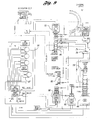
- FIG 1 shows a signal flow overview for the transmission.
- the shift solenoid and shift valve configuration is generally similar to the four-speed transmission of the co-pending '464 application.
- two additional signals have been added, which are the overdrive drum speed (ODS) and the output shaft speed (OSS).
- ODS overdrive drum speed
- OSS output shaft speed
- the following signals are used by the transmission control strategy to execute the 2-3 shift, the 3-2 shift and the 4-2 shift.
- the signals are generated from the following inputs:
- the control algorithms of the transmission strategy determine in which manner the 2-3 upshift and the 3-2/4-2 downshift are executed based on the input signals and calibration data.
- the transmission operation during swap-shift execution is basically broken down into the following two major events:
- the transmission actuators convert the electrical signals generated from the control algorithm into either a hydraulic signal pressure or pressures directly applied to clutches or brake bands. Shift valves and modulator valves are actuated by these signal pressures. It is the purpose of these shift valves to release or to apply hydraulic pressure for the torque transmitting elements (clutches and bands). The pressure modulator valves adjust the amount of frictional capacity applied on the friction elements.
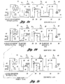
- the torque flow is generally similar to the previously mentioned four-speed transmission except that the overdrive planetary gearset is engaged in first gear to generate the 1.855 gear ratio.
- Figures 2a-2c show the torque flow only in the first three gears; which are first, second, and third gears.
- the fourth gear is the same as third gear in the four speed transmission and the fifth gear is the same as fourth gear in the four speed transmission.
- Engine torque is delivered to the pump housing; i.e., the torque converter impeller 10.
- the converter impeller is a centrifugal pump that accelerates fluid inside of the torque converter toward the turbine blades 12.
- the accelerated oil is then decelerated over the turbine blades, and the remaining oil is redirected over the reactor 14 back into the impeller, which achieves a torque multiplication effect.
- the torque is transmitted to OWC1, which holds the reactor against rotation in the rotational direction of the engine and overruns in the opposite direction.
- the engaged clutch CL3, shown at 18, carries the torque from the centre shaft to the input element of the Simpson planetary gear arrangement 22 (see Figure 2a).
- the torque is distributed to the ring gear and is then split into two components.
- One torque component is delivered over the planetary carrier 24 to the output shaft, which turns in the same rotational direction as the ring gear 26.
- the sun gear 28 carries the remaining component of the torque in reverse motion to the rear sun gear 30 of the Simpson planetary gearset.
- the planetary carrier 32 of the rear planetary gearset is held by OWC2, shown at 34.
- the torque delivered by the sun gear 30 is then transmitted over the planetaries to the ring gear 36, which reduces the velocity and multiplies the torque to the output shaft 38.
- This arrangement provides a 2.474 gear ratio.
- Second gear is generated by the engagement of brake 42 (B1), which is the overdrive band.
- CL2, B2, and B3, shown at 44, 46 and 48, respectively, are still disengaged.
- B1 (see Figure 2b) carries 0.25*engine torque as a reaction torque.
- the sun gear of the overdrive planetary gearset is decelerated to zero speed and generates an overall gear ratio of 1.855, which consists of the first gear ratio 2.474 times the overdrive gear ratio, which is 0.75.
- the engagement of CL1, shown at 50 is hydraulically inhibited when B1 is applied. With the engagement of B1, the reaction torque on OWC1 is reduced until the one-way clutch overruns.
- the converter clutch can be locked or unlocked in second gear depending on the driving condition.
- the torque flow is the same as in second gear, except that B2 is applied and B1 is released. With the engagement of B2, the sun gear speed of the rear Simpson set 22 is reduced to zero.
- the brake band (B2) serves as a reaction element for the front gear unit of the Simpson planetary gearset.
- An output torque multiplication of 1.474 occurs by holding 0.474*engine torque as a reaction torque.
- the output of the rear Simpson planetary gearset is zero since the sun gear has zero speed.
- the converter clutch can be locked or unlocked in third gear depending on the driving condition.
- the gear change from second to third is illustrated in Figure 2c.
- the gear ratio change is accomplished by releasing B1 and applying B2 at the same time. This disengages planetary gearset P1 and engages planetary gearset P2. During a downshift, the engaging sequence is reversed.
- SWAP-SHIFT Synchronous Shift Control of 2-3 Upshift
- SWAP-SHIFT Synchronous Shift Control of 2-3 Upshift
- SWAP-SHIFT Synchronous Shift Control of 2-3 Upshift
- SWAP-SHIFT Synchronous Shift Control of 2-3 Upshift
- SWAP-SHIFT Synchronous Shift Control of 2-3 Upshift
- SWAP-SHIFT 3-2/4-2 Downshift
- the transmission has the following additional types of synchronous shifts: SHIFTS SYNCHRONOUS 2- Reaction-to-Reaction (B1/OWC1 to B2/OWC2) 3 3- Reaction-to-Reaction (B2/OWC2 TO B1/OWC1) 2 4- Drive-to-Reaction (CL2 to B1/OWC1) 2
- This section describes the shift dynamics of synchronous 2-3 upshifts and 3-2/4-2 downshifts. Pressure control and the resulting torque disturbance of the electronic control system is described in general to accomplish the SWAP-SHIFT. How the electronic control system executes the upshifts and downshifts is described subsequently.
- the synchronous 2-3 upshift is a reaction-to-reaction shift.
- Reaction-to-reaction means, in this case, a change from one reaction element to another reaction element.
- the 2-3 upshift of the five-speed transmission is a gear ratio change where two independent, in-series, compounded planetary gearsets are upshifted and downshifted, respectively.
- the overdrive planetary gearset (P1) is downshifted and the Simpson planetary gearset 22 is upshifted.
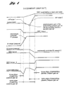
- the ultimate goal is to synchronise both shifting events without losing capacity of one of the affected elements at the finishing point of the upshifted Simpson gearset (see Figure 3).
- the shift is initiated by engaging B2 and increasing B2 capacity. This reduces the OWC2 torque down to zero level.
- the output shaft torque follows the OWC2 torque up to the point where B2 torque is equal to the reaction torque of OWC2.
- the output shaft torque follows the B2 pressure characteristic and OWC2 starts to rotate, as shown at 52 in Figure 3.
- the inertia phase of the upshifting event is initiated and "shift slope 1" is generated.
- the downshifting event of the overdrive planetary gearset is enabled. This is accomplished by reducing B1 capacity.
- the output shaft torque characteristic follows the B1 pressure characteristic, and the OWC2 speed relative to input shaft speed is reduced.
- a second shift slope, called “shift slope 2" is started at 54 (see Figure 3).
- OWC2 carries torque.
- the torque phase of the downshifting overdrive planetary gearset is then complete.
- the electronic control system has to satisfy the following requirements in order to accomplish satisfactory 2-3 upshift quality:
- the synchronisation of both shifting events has to be completed at the completion, or just before the completion, of the inertia phase of the upshifting Simpson set 22.
- the engagement of OWC2 has to be controlled by accumulating the B1 capacity. This requires electronic control of band capacity and electronic control of upshift and downshift execution as well as monitoring the upshifting and downshifting events.
- the synchronisation has to take place within a defined calibration window (see Figure 3) in order to prevent a gear ratio change into the next higher gear. This can occur when the downshifting takes place too late. Similarly, if the downshifting event takes place too early, capacity loss takes place since the transmission shifts back into first gear.
- a conventional, hydraulically controlled transmission is not capable of executing these two upshifting events.
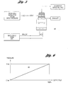
- the synchronous 3-2/4-2 downshift is reaction-to-reaction (3-2) and a drive-to-reaction (4-2) shift.
- Drive-to-reaction means that a rotating clutch is shifted to a reaction element, which is B1.
- B1 This is the inverse of the 2-3 upshift in which the overdrive planetary gearset is downshifted as the Simpson gearset is upshifted.
- B2 On a downshift, the overdrive planetary gearset is upshifted, whereas the Simpson gearset 22 is downshifted.
- B2 is released; and in the case of a 4-2 downshift, CL2 is released.
- the upshifting event of the overdrive planetary gearset must take place first; and when B1 carries full capacity, the downshifting of the Simpson set can be initiated.
- the graph of Figure 4 illustrates this shifting process.
- B1 pressure is increased, which reduces OWC1 torque to zero.
- the inertia phase of the upshifting overdrive planetary gearset is initiated when OWC1 torque is zero, generating "shift slope 1".
- the transmission shifts first to the next possible higher gear.
- the synchronisation point is determined by the amount of the overdrive upshift progression.
- B2 pressure is released and OWC2 speed is reduced by input shaft torque and the "shift slope 2" is started.
- the B2 pressure characteristic must be capable of accumulating torque to ensure a smooth OWC2 engagement.
- the downshift is complete when OWC2 transmits full torque.
- B1 and B2 have to be electronically controlled; and they require independent control systems. Both B1 and B2 pressure characteristics should be able to accumulate for smooth one-way clutch engagements.
- the synchronisation point has to be detected by monitoring turbine speed and overdrive drum speed, which basically represents the OWC1 speed relative to input shaft speed.
- the electronic control system of the five-speed transmission of the invention is capable of controlling the above described shifts.
- the complete control system and its functional requirements, explained above, are described subsequently.
- second gear solenoid stage and intermediate step 3 (IS3).
- This intermediate step 3 is used to initiate the 2-3 upshift and the 3-2 downshift.
- the solenoid stages for first, third, 1S1, 1S2, fourth and fifth gears are the same as those stages found in the previously described four-speed transmission except that third, fourth, and fifth gear are equivalent to second, third, and fourth gear for the four-speed transmission.
- the control system contains three shift solenoids SS1, SS2, and SS3 for shift execution.
- SS2 and SS3 are seen in Figures 10-12.
- eight solenoid stages are required to realise first, second, 1S3, third, 1S2, 1S1, fourth, and fifth gear.
- Shift solenoid SS4 seen at 58 in Figures 5 and 9, is used for the overdrive cancel function and for overdrive band capacity control. This will be explained subsequently.
- the electronic-mechanical interface (seen in Figure 1) contains also the hydraulic control system which transforms the solenoid stages into shifting action. This description is concerned principally with second gear stage, intermediate step 3 and third gear stage.
- the solenoid stage in these positions is the first gear stage, which is equivalent to that of the four-speed transmission.
- the sensors and actuators are common to those of the four-speed transmission. There are two additional transmission sensors added, which are the overdrive drum speed sensor (ODS) and the output shaft speed sensor (OSS). With the output shaft speed and overdrive drum speed signals, along with the turbine speed signal (TS), all velocities and ratios for the overdrive planetary gearset, as well as the Simpson planetary gearset, are determined.
- ODS overdrive drum speed sensor
- OSS output shaft speed sensor
- Overdrive drum speed sensor 56 senses the speed of the overdrive drum (CL1). It is a variable reluctance sensor.
- the overdrive drum contains 24 teeth in order to trigger the overdrive drum speed signal.
- the overdrive drum is connected to the sun gear of the overdrive planetary gearset, and the overdrive drum speed sensor (ODS) monitors the sun gear speed.
- the sensor has the following characteristic data:
- the ODS sensor monitors the sun gear speed of the overdrive planetary gearset to effect control of the overdrive band capacity during a 2-3 upshift as well as the 3-2/4-2 downshifts. It will also be used for 5-4 downshifts and 4-5 upshifts.
- the output shaft speed sensor 97 which senses the speed of the output shaft, is a variable reluctance sensor.
- the output shaft trigger wheel contains 8 teeth in order to trigger the output shaft signal.
- the output shaft speed sensor 97 is used to generate a more accurate signal compared to the vehicle speed sensor, shown at 99 in Figure 10a.
- the output shaft speed signal is required to determine a reliable value for the transmission ratio variable (RT TRANS).
- the shift solenoids are used to transform an electrical signal of zero to 12 V into an output pressure of zero to 5 bar.
- the shift solenoid 58 seen in Figure 5
- shift solenoid 58 is used to control the coast clutch when the overdrive cancel function is executed.
- shift solenoid 58 is used in addition to the overdrive cancel function as a capacity control actuator for the overdrive band capacity adjustment (see Figure 6).
- the shift solenoid is applied with a duty cycled electrical input signal similar to the PWM-solenoid for the converter clutch.
- the input pressure is SOL2 pressure, which varies between 4-5 bar.
- This input pressure is modulated by the duty cycle input into a transfer function as shown in the graph of Figure 6.
- the transfer function may be represented as a straight line 60.
- the output pressure is applied to the overdrive servo release side, thus controlling the overdrive band B1 capacity.
- SS4 now acts as an ON/OFF device as well as a pressure regulator system.
- the basic control strategy of the invention in some respects is common to that of the four-speed transmission.
- the new strategy for the five-speed transmission is explained in detail subsequently.
- RT_CORR is a calibratable value used to control the starting point of the ODS_TRG_FG signal in shift interval to enhance upshift and downshift control.
- the hydraulic control system as well as the control strategy for the dedicated functions of the transmission now will be described.
- the hydraulic control system is basically the same as that of the four-speed system, except shift solenoid 58 is controlled differently and the overdrive drum speed sensor 56 is used for feedback control.
- the functional description includes only the 2-3 upshift control and the 3-2/4-2 downshift control since everything else is common to the four-speed transmission.
- the hydraulic control system for accomplishing a 2-3 upshift, as well as a 3-2/4-2 downshift consists of the following hardware components:
- the pressure build-up system is common to the four-speed transmission, as mentioned above.
- the detailed description of the four-speed version of the '464 application is incorporated by reference in this disclosure.
- the hydraulic control system consists of three different pressure systems:
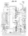
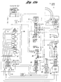
- the hydraulic control system for controlling execution of a 2-3 upshift is shown in Figures 9, 10, 11a, 11b, 12a and 12b.
- the new second gear embodied in the five-speed transmission is shown in Figures 9 and 10.
- the shift solenoid (SS4), shown at 58, can be duty-cycle controlled or actuated as an ON/OFF solenoid.
- an intermediate step 3 is introduced, which initiates the upshifting event of the Simpson planetary gearset 22.
- the overdrive planetary gearset is upshifted, in addition to the first gear ratio of the Simpson sets, giving a gear ratio of 1.85.
- shift solenoid 72 SS3
- the 3-4 shift control valve moves into upshift position. This disconnects line pressure from the overdrive servo release (OSR) side and connects the OSR side with the shift solenoid 58 circuitry.
- This circuitry is called OSR/EX/SS4.
- orifice 74 closed and orifice 76 opened and with the upshifting of valve 84 in bore 215 the OSR side is connected to the duty cycle controlled shift solenoid 58.
- the overdrive servo apply side is always applied with CF-pressure produced by the clutch pressure modulator forward in bore 207.
- the OSR release oil is exhausted through shift solenoid 58.
- the intermediate servo apply side is exhausted over the 1-2 shift valve in bore 203 and the 2-3 upshift valve in bore 204 into the ISA/EX port.
- the intermediate servo release side and the high clutch CL2 are exhausted also over the 1-2 upshift valve 94 in bore 204 and the 2-3 upshift valve 78 (Fig. llb) in bore 204 into the CR/R/EX port.
- shift solenoid 80 (SS2) is energised.
- the energised shift solenoid 80 moves the 1-2 upshift valve 78 into upshift position. This is shown in Figure lla.
- the upshifted 1-2 upshift valve 78 connects the intermediate servo apply side (ISA) with CF-pressure and the intermediate servo starts to engage. This initiates the 2-3 upshift by upshifting the Simpson planetary gearset 22, as explained earlier.
- ISA intermediate servo apply side
- the intermediate servo starts to engage.
- This initiates the 2-3 upshift by upshifting the Simpson planetary gearset 22, as explained earlier.
- independent capacity control would not be possible if a signal pressure controller were to be used.
- With the shift solenoid 58 connected to the OSR side however, independent control of the overdrive band capacity is possible relative to the intermediate band capacity.
- the transmission is in the intermediate step 3 (IS3) stage.
- the downshifting of the overdrive planetary gearset is controlled; first of all by controlling the pressure on the overdrive servo release side by applying a duty cycle to shift solenoid 4.
- This controls capacity of overdrive band 42 and thereby controls the amount of torque applied to OWC1.
- TS turbine speed
- ODS overdrive drum speed
- the upshifting of the Simpson set 22 and the downshifting of the overdrive planetary gearset can be synchronised.
- the coast clutch 50 (CL1) is exhausted over the upshifted coast clutch control valve 82 in bore 201 and upshifted 3-4 shift valve 84 in bore 215.
- the same swap-shift can be controlled in an optional construction without capacity control of the overdrive band. This is accomplished by closing orifice 76 and opening orifice 74. This disconnects the overdrive servo release side from shift solenoid 58 and connects the OSR side over the shift valve in bore 212 to the CL1/B1/EX port. However, this disables the independent control feature of the overdrive band 42, but it produces the option of engaging and releasing the overdrive band through a wide open exhaust. This protects the overdrive band lifetime durability in case of an overloading of the overdrive band using SS4 capacity control. The shift quality, however, will be influenced by this optional shift control method. The same effect is also accomplished without using this optional feature and leaving the shift solenoid turned off.
- the execution of a 2-3 upshift involves a sequence of events and control actions with interaction between the control strategy and the control hardware.
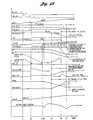
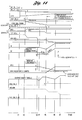
- the timing diagram shown in Figure 13 shows the execution of a 2-3 upshift. Control strategy as well as the hardware behaviour are illustrated in this timing diagram.
- a 2-3 upshift is triggered by the control strategy based on functions of vehicle speed versus throttle position. Desired gear (GR_DS) is changed from second gear to third gear and the shift verification timer (TM_VER_SFT) is loaded. The dynamic EPC value is added for third gear.
- Desired gear GR_DS
- TM_VER_SFT shift verification timer
- the EPC values are raised according to the commanded EPC values.
- the shift verification timer TM_VER_SFT is expired and the gear commanded register GR_CM is changed from second to third gear.
- An initial duty cycle of shift solenoid 58 is loaded into the SS4_DC register. This initial duty cycle is required to pre-fill the release side of the overdrive servo 88 prior to the shift execution.
- the 2-3 upshift start timer TM_23_STRT is loaded. This timer is required to initiate a start duty cycle independent of the expiration of the shift verification timer TM_VER_SFT. When this timer is expired, a start duty cycle is set prior to closed loop capacity control of the overdrive band 42. An initial slip value, depending on the duty cycle value, could be introduced to the overdrive band in an open loop control manner.
- the TM_23_STRT timer is a function of transmission oil temperature since the applied pressure varies with duty cycle and temperature. At this point, the following important calibration parameters are calculated:
- the overdrive drum speed target value ODS_TRG is calculated based on a function FNODS_CMPT, which contains a multiplier of overdrive drum speed as a function of output shaft speed NOBART. This is calculated based on the actual output shaft speed times the gear ratio after completion of the shift (GRRAT3).
- the gear ratio threshold value RT_23_TRG then is calculated based on a function FN23CMPF, percentage shift complete PCSFTCMPT, versus output shaft speed NOBART in order to initiate the start of closed loop capacity control of the overdrive band using the shift solenoid duty cycle SS4_DC.
- a further gear ratio threshold value RT_SFT_END is calculated to decide the end of closed loop capacity control and to release the overdrive band capacity completely. These values are compared later with the continuously calculated variable RT_TRANS and are used for the above described functions. Shift solenoid flag 2 (FLG_SS_2) is set to 1 and the EPC-RMP timer is loaded. The EPC ramp is now executed.
- Shift solenoid 80 is energised and the 1-2 upshift valve 78 in bore 203 moves into upshift position.
- CF-pressure produced from the clutch pressure modulator forward in bore 207 is applied to the apply side of the intermediate servo 90.
- the characteristic of this forward modulator 92 allows capacity control from zero to maximum capacity.
- the intermediate band is engaged and takes the torque of the sun gear of the Simpson planetary gearset 22.
- the reaction torque on overrunning brake 34 (OWC2) is reduced.
- the output shaft torque follows first the reaction torque characteristic of OWC2.
- the torque phase of the 2-3 swap-shift is initiated (see also Figure 3).
- the overdrive servo release pressure which is actual SS4 output pressure, builds up to a level where no capacity loss on the overdrive band takes place.
- the duty cycle start timer (TM_23_STRT) is expired.
- the start duty cycle (SS4_DC_BRK) is loaded into the SS4_DC register, as seen in Figure 7 and Figure 13.
- SS4_DC_BRK is the break-away duty cycle for overdrive brake capacity.
- the pressure is increased on the release side of the overdrive servo 88 since the shift solenoid duty cycle has been increased.
- the overdrive band capacity can be manipulated by SS4 duty cycle settings and an overdrive drum slip can be introduced prior to closed loop control of the overdrive band capacity.
- the RT_TRANS value is continuously calculated based on turbine speed and output shaft speed.
- the RT_TRANS value starts to decrease when the inertia phase of the 2-3 upshift is started and the torque phase is completed.
- the shift starts with a shift slope 1 ( Figure 13) which is entirely dependent on the CF pressure settings and the commanded EPC ramp.
- the torque phase of the upshifting event of the Simpson planetary gearset 22 is completed, and the output shaft torque is completely dependent on the applied capacity of the intermediate band.
- the reaction torque on one-way clutch 34 (OWC2) is zero, and the high clutch drum speed (HCDS) starts to decelerate.
- the output shaft torque is reversed since the reaction torque is zero and ISA pressure increases capacity.
- the overdrive drum speed remains at zero speed.
- Option 2 With option 2, the ODS_TRG value is converted into a target value which is synchronised with the continuation of the shifting event.
- the overdrive drum speed target value is directly connected to the RT_TRANS calculation.
- SS4_DC SS4_DC_BRK + (ODS - ODSS_TRG_FG)/ (ODSS_TRG_FG * OL_CORR)
- the duty cycle calculation in each option takes the error between the actual overdrive drum speed ODS and the target overdrive drum speed into account and converts the calculated error in the duty cycle for shift solenoid 58. This adjusts the overdrive band capacity accordingly. Based on the capacity control on the overdrive band 42, a "shift slope 2" is initiated, which begins the downshifting event of the overdrive planetary gearset.
- the timer SS4_END_TMR is loaded and kept high. This timer is needed to compensate for the SS3 pressure exhaust delay time.
- the overdrive servo release pressure is either increased or decreased based on the duty cycle of solenoid 58.
- a second shift slope is introduced due to overdrive band capacity control and the additional overdrive band slip.
- the overdrive drum speed starts to follow the target value ODS_TRG. Independent control of the overdrive planetary gearset is initiated.
- the output shaft torque decreases since the capacity on the overdrive band is decreased as well.
- the RT_TRANS value is smaller than the second ratio threshold RT_SFT_END.
- the closed loop control of the overdrive band is terminated by setting the shift solenoid flag 3 FLG_SS_3 to zero.
- the duty cycle calculation for SS4 shift solenoid 58 is still kept high. This is the initiation of the synchronisation between the downshifting of the overdrive planetary gearset and the upshifting of the Simpson gearset 22.
- Shift solenoid 72 (SS3) is de-energised and the 3-4 upshift valve 84 moves into downshift position.
- the shift solenoid 58 output pressure is disconnected from the overdrive servo release side and line pressure is connected. This reduces the overdrive band capacity completely, and OWC1 takes the remaining inertia and starts to transmit full torque.
- the output pressure of the shift solenoid 58 stays high in order to keep the overdrive servo release area pressurised. From time point t5 to time point t6, downshift accumulation takes place for the overdrive planetary gearset in order to accomplish a smooth one-way clutch engagement of OWC1.
- This accumulation phase is also used to synchronise the downshifting of the overdrive planetary gearset and the upshifting of the Simpson set 22 using feedback control with overdrive drum speed.
- the hatched area of the overdrive servo release area ( Figure 13) indicates the time where independent capacity control takes place following time t3 using open loop control and closed loop control executed by SS4 for the overdrive gearset and the Simpson set.
- the overdrive servo release pressure is line pressure.
- the output shaft torque characteristic shows another negative slope since the overdrive band has zero capacity.
- the EPC_RMP timer has expired and the EPC ramp is terminated.
- the timer SS4_END_TMR can expire before or beyond t7 since this time is used for SS3 pressure exhaust synchronisation.
- timer SS4_END_TMR is expired, the SS4_DC register is set to zero since full line pressure is then connected to the overdrive servo release chamber.
- the overdrive drum has reached engine speed and OWC1 is fully engaged.
- the high clutch drum speed (HCDS) is at zero speed.
- the output shaft torque characteristic is now reversed again since OWC1 then carries full torque.
- the torque phase of the downshifting event is initiated and the 2-3 upshift is complete.
- Time pressure is connected to the overdrive servo release chamber. This is the synchronisation point for the downshifting overdrive gearset and the upshifting Simpson set within the calibration window shown in Figure 3.
- the functioning of the 3-2/4-2 downshift control system is the inverse of the 2-3 upshift event; i.e., the overdrive planetary gearset upshifts and the Simpson set 22 downshifts in a synchronised manner.
- the Simpson set is downshifted by releasing the intermediate servo 90 for band (B2), and the OWC2 engages after the inertia phase.
- the Simpson set 22 is downshifted by releasing the high clutch (CL2).
- the gear ratio is changed from 1.474 to 1.86
- the gear ratio is changed from 1 to 1.86.
- the solenoid stages during a 3-2 downshift is the inverse of the 2-3 upshift, except shift solenoid 58 (SS4) is not duty cycle controlled.
- the 4-2 downshift can be executed either in sequence, which means 4-3-2, or directly as a 4-2 downshift.
- the shift sequence is shown as follows:
- the sequenced 4-3-2 downshift is basically the execution of a 4-3 downshift, which is the same as the 3-2 downshift of the four-speed transmission, followed by the 3-2 (SWAP-SHIFT) downshift.
- the control hardware uses the 5 th gear solenoid stage as an intermediate step to initiate the 4-2 downshift, as shown in the above tables.
- Figures 9, 10, 11a, 11b, 12a and 12b show the 3-2 downshift hydraulic control system.
- the intermediate servo i.e., band B2
- the high clutch (CL2) is exhausted over the 2-3 upshift valve 94 in bore 204.
- the shift solenoid 3 is energised and the 3-4 upshift valve moves into upshift position.
- the transmission is now in intermediate step 3 shown in Figure 11.
- the overdrive servo release circuit which was previously applied with line pressure, is now exhausted over orifice 76 through the exhaust port of shift solenoid 58.
- the overdrive servo apply side is continuously applied with CF modulator pressure produced by the clutch pressure modulator valve 92 in bore 207.
- the overdrive servo is applied and initiates a 3-2 downshift by upshifting the overdrive planetary gearset.
- the transmission is commanded to execute the second gear solenoid stage as shown in Figures 9 and 10.
- the duty cycle controlled shift solenoid 58 is de-energised.
- Shift solenoid 80 (SS2) is turned off.
- the shift solenoid 80 de-energised With the shift solenoid 80 de-energised, the 1-2 upshift valve 78 in bore 203 moves into downshift position and the intermediate servo apply pressure is exhausted over the CF/3/4/EX circuit through the ISA/EX port located on the downshifted 2-3 upshift valve 94.
- Shift solenoid SS1 always stays on during the 3-2 downshift event and keeps the high clutch 44 always exhausted, together with upshifted 2-3 upshift valve 94 in bore 204.
- the 3-2 downshift is now complete.
- the 2-3 upshift valve 94 is in the downshift position and D/2/1 pressure is present in the high clutch circuit. This can be seen in Figure 12b where the shift valve 94 in bore 204 is shown in upshift position.
- the overdrive planetary gearset has to be upshifted.- This can only be accomplished by energising shift solenoid 72 (SS3) first. With shift solenoid 72 turned on, the transmission is in the 5 th gear solenoid stage, which corresponds to the 4 th gear solenoid stage in the four-speed transmission. When shift solenoid 72 is energised, the overdrive servo release pressure is exhausted over orifice 76 through the exhaust port of shift solenoid 58 (SS4). The overdrive servo apply is pressurised with CF pressure and the overdrive band engages. This initiates the 4-2 downshift.
- shift solenoid 72 shift solenoid 72
- SS4 shift solenoid 58
- the downshifting event of the Simpson planetary gearset is initiated. This is done by energising shift solenoid SS1. Shift solenoid 80 (SS2) stays de-energised. With shift solenoid SS1 energised, the 2-3 upshift valve 94 moves into upshift position. The 1-2 upshift valve 78 in bore 203 is in downshift position. The upshifted 2-3 shift valve 94 in bore 204 opens the ISA/EX port as well as the CR/R/EX port. The intermediate servo apply pressure is exhausted over the ISA/EX port and the high clutch (CL2) is exhausted through the CR/R/EX port. The 4-2 downshift is now complete.
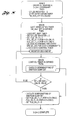
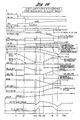
- Figure 14 shows the timing diagram for a 3-2/4-2 downshift. This illustrates the interactive functions of hardware and control strategy during the 3-2/4-2 downshift event. The broken lines in Figure 14 show the additional and actions in a 4-2 downshift.
- a 3-2/4-2 downshift is triggered by the control strategy based on the function of vehicle speed versus throttle position.
- GR_DS is changed from third gear or fourth gear to second gear, and the shift verification timer TM_VER_SFT is loaded.
- the dynamic EPC value is added for second gear.
- the EPC values are raised according to the commanded EPC values.
- the shift verification timer TM_VER_SFT is expired, and the gear commanded register GR_CM is changed from fourth or third to second gear.
- a 3-2/4-2 control timer is loaded. At the same time, overdrive drum speed and turbine speed are monitored to sense the start of the downshifting event. The control timer is required in order to control the 3-2/4-2 downshift independently of the speed signals. This is needed in the event that the speed signals are not available. Shift solenoid flag 3 FLG_SS_3 is set to 1 and the EPC-RMP timer is loaded. The EPC ramp then is executed.
- Shift solenoid 72 (SS3) is energised and the 3-4 shift control valve 84 in bore 215 moves into upshift position.
- CF-pressure produced from the clutch pressure modulator valve (forward) 92 in bore 207 is applied to the overdrive servo apply side, and the overdrive servo starts to stroke.
- the control strategy monitors overdrive drum speed (ODS) and turbine speed (NT).
- the overdrive servo is engaged with CF pressure.
- the characteristic of this modulator valve 92 allows capacity control from 0 to maximum capacity.
- the overdrive band engages and takes the torque of the sun gear from the overdrive planetary gearset.
- the reaction torque on OWC1 relative to the input torque is reduced.
- the output shaft torque is determined first by the reaction torque characteristic of OWC1.
- the torque phase of the 3-2/4-2 swap-shift is initiated with the upshifting of the overdrive planetary gearset.
- the turbine speed value (NT) and the overdrive drum speed value (ODS) start to decrease since the inertia phase of the 3-2/4-2 shift is started and the torque phase is completed. Both speed signals are still being monitored.
- the shift starts with a "shift slope 1" (see Figure 14), which is entirely dependent on the CF pressure settings on the overdrive band according to the commanded EPC ramp.
- the torque phase of the upshifting overdrive planetary gearset is completed and the output shaft torque is completely dependent on the applied capacity on the overdrive band 42.
- the reaction torque on one-way clutch 16 (OWC1) is zero and the overdrive drum speed (ODS) starts to decrease.
- OCS overdrive drum speed
- the output shaft torque is reversed since the reaction torque is zero and OSA pressure is increasing.
- the high drum still stays at zero speed.
- the intermediate band is released and the high clutch is applied for 4 th gear.
- the high clutch drum turns clockwise in this case, the same direction as engine speed.
- the shift solenoid flag 2 (FLG_SS_2) is set to zero during a 3-2 downshift.
- the 3-2/4-2 control timer is expired, allowing 3-2/4-2 downshift execution.
- a "shift slope 2" is initiated (see Figure 14).
- the control strategy has sensed that enough capacity is transmitted by the engaged overdrive band. This represents the feedback of the control system for executing a 3-2/4-2 downshift.
- the shift solenoid flag 2, FLG_SS_2 is zero and stays zero.
- the shift solenoid flag 1, FLG_SS_1 is set to 1, initiating the downshift of Simpson planetary gearset 22.
- the intermediate servo apply pressure is exhausted by the de-energised shift solenoid 80 (SS2), which makes the 1-2 upshift valve 78 in bore 203 move to downshift position.
- the shift solenoid SS1 is energised and the 2-3 upshift valve 94 in bore 204 is in downshift position.
- a second shift slope is introduced due to the reduced capacity of the intermediate band 46.
- the high clutch drum speed starts to accelerate from zero rpm.
- the output shaft torque decreases since-the capacity of the intermediate band 46 is decreased as well.
- the shift solenoid 80 (SS2) stays de-energised.
- High clutch 44 is pressurised with D/2/1 pressure and the apply side of the intermediate servo is energised with CF pressure.
- the high clutch drum rotates in the direction of the engine speed with the value of engine speed.
- shift solenoid SS1 is energised, the intermediate servo apply pressure and the high clutch pressure are exhausted, and the high clutch drum is first decelerated down to zero speed by the input torque. Then the high clutch is accelerated in the direction opposite to the rotational direction of the engine speed up to the point when overrunning clutch 34 (OWC2) is engaged.
- OBC2 overrunning clutch 34
- the EPC_RMP timer expires and the EPC ramp is terminated.
- the high clutch drum has reached its rotational speed and the overrunning clutch 34 (OWC2) is fully engaged.
- the overdrive drum speed (ODS) is zero.
- the output shaft torque characteristic is now reversed again since OWC2 now carries full torque.
- the torque phase of the downshifting Simpson gearset is initiated and the inertia phase is completed.
- the 3-2/4-2 downshift then is completed.
- the flowchart of Figure 8 shows the control strategy during a 3-2/4-2 downshift.
- Option 1 This option has an Overdrive Drum Speed Sensor and is Closed Loop controlled.
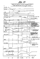
- the Figures 15 and 16 show the logic and the execution of the calibration option during a 2-3 upshift interval.
- the execution of a 2-3 upshift is a sequence of events and control actions with interaction between the control strategy and the control hardware.
- the timing diagram shown in Figure 15 represents the execution of a 2-3 upshift during the shift interval.
- Control strategy as well as the hardware executing actions are illustrated in the diagram of Figure 16.
- the driver desires a 2-3 upshift which is triggered by a control strategy based on functions of vehicle speed versus throttle position.
- the gear desired GR_DS is changed from 2 nd gear to 3 rd gear and the shift verification timer TM_VER_SFT is loaded.
- the dynamic electronic pressure control (EPC) value is added for third gear.
- An initial duty cycle of shift solenoid 4 is loaded into the SS4_DC register. This initial cycle is required to pre-fill the overdrive servo release side prior to shift execution.
- the 2-3 upshift start timer TM_23_STRT is loaded. This timer is required to initiate a start duty cycle independent of the expiration of the shift verification timer TM_VER_SFT. When this timer is expired, a start duty cycle is set prior to closed loop capacity control of the overdrive band.
- the TM_23_STRT timer is a function of transmission oil temperature since the applied pressure varies with duty cycle and temperature.
- the EPC values are raised according to the commanded EPC values.
- the overdrive servo release pressure which is actual SS4 output pressure, builds up to a level where no capacity loss on the overdrive brake band takes place.
- the shift verification timer TM_VER_SFT is expired and the gear commanded register GR_CM is changed from 2 nd to 3 rd gear.
- ODS_TRG NOBART*GRRAT3*FNODS_CMPT(NOBART)
- RT_SFT_END GRRAT2 + [FNPCSFT23(TP_REL)*(GRRAT3 GRRAT2)]
- the overdrive drum speed target value ODS_TRG is calculated based on a function FNODS_CMPT, which contains a multiplier of overdrive drum speed as a function of output shaft speed NOBART. This speed is calculated based on the actual output shaft speed times the gear ratio after completion of the shift (GRRAT3).
- the gear ratio threshold value RT_SFT_END is calculated to determine the end of closed loop capacity control and to release the overdrive band capacity completely. These values are compared later with continuously calculated RT_TRANS and are used for the above described functions.
- the ODS_TRG value is converted into a target value which is synchronised with the continuation of the upshifting event of the Simpson set.
- the overdrive drum speed target value is directly involved in the RT_TRANS calculation.
- the SS4_DC value is then later calculated based on the ODSS_TRG_FG value.
- Shift solenoid flag 2 FLG_SS_2 is set to 1 and the EPC-RMP timer is loaded. The EPC pressure ramp then is executed.
- An initial duty cycle of shift solenoid 4 is loaded into the SS4_DC register. This initial duty cycle is required to pre-fill the overdrive servo release side prior to the shift execution.
- the 2-3 upshift start timer TM_23_STRT is loaded. This timer is required to initiate a start duty cycle independent of the expiration of the shift verification timer TM_VER_SFT. When this timer is expired, a start duty cycle is set prior to closed loop capacity control of the overdrive band.
- the TM_23_STRT timer is a function of transmission oil temperature since the applied-pressure varies with duty cycle and temperature.
- Shift solenoid 2 is energised and the 1-2 upshift valve in bore 203 moves into upshift position.
- CF pressure produced from the clutch pressure modulator forward valve in bore 207 is applied to the intermediate servo apply side. The characteristic of this forward modulator valve allows capacity control from zero to maximum capacity.
- the intermediate band engages and takes the torque of the sun gear from the Simpson planetary gearset.
- the reaction torque on OWC2 is reduced.
- the output shaft torque follows initially the reaction torque characteristic of OWC2.
- the torque phase of the 2-3 swap shift at that instant is initiated.
- the overdrive servo release pressure which is actual SS4 output pressure, builds up to a level where no capacity loss on the overdrive brake band takes place.
- the duty cycle start timer TM_23_STRT is expired.
- the start duty cycle SS4_DC_BRK is loaded into the SS4_DC register.
- SS4_DC_+BRK Break away duty cycle for overdrive band capacity.
- the pressure is increased on the overdrive servo release side since the shift solenoid 4 (SS4) duty cycle has been increased.
- the overdrive band capacity can be manipulated by the SS4 duty cycle settings.
- the SS4 duty cycle setting has a value which allows the initiation of the downshifting of the overdrive planetary gearset triggered by the additional torque TQ_I ⁇ _SIMP imparted from the upshifting Simpson planetary gearset. The torque phase of the upshifting Simpson set is initiated.
- the RT_TRANS value is calculated continuously based on turbine speed and output shaft speed.
- the RT_TRANS value starts to decrease since the inertia phase of the 2-3 upshift is started and the torque phase is completed.
- the shift starts with a shift slope 1, which is entirely dependent on the CF pressure settings and the commanded EPC ramp.
- the torque phase of the upshifting event for the Simpson planetary gearset is completed and the output shaft torque is completely dependent on the applied capacity on the intermediate band.
- the reaction torque on one-way clutch 2 (OWC2) is zero and the high clutch drum speed (HCDS) starts to decelerate.
- the output shaft torque is reversed since the reaction torque is zero and ISA pressure capacity is increasing.
- the inertia phase of the Simpson planetary gearset is initiated.
- the TQ_I ⁇ _SIMP value which is the reaction torque of the inertia torque of the Simpson set, increases.
- the total Overdrive torque consisting of TQ_I ⁇ _SIMP and static brake torque, has reached a level which exceeds the overdrive band capacity.
- the overdrive drum speed starts to rise.
- the calculated ODS and ODS_TRG_FG values start to rise.
- the shift slope 2 is initiated.
- the ODS_TRG value is converted into a target value which is synchronised with the continuation of the shifting event.
- the overdrive drum speed target value is directly connected to the RT_TRANS calculation.
- the overdrive drum target speed ODS_TRG value is then decreased from the initial value calculated previously in accordance with the following calculation:
- ODSS_TRG_FG ODS_TRG*(GRRAT2 - RT_TRANS - RT_CORR)/(GRRAT2 - GRRAT3)
- ODSS_TRG_FG is the overdrive drum speed target value depending on the upshifting event of the Simpson set with respect to actual gear ratio.
- SS4_DC SS4_DC_BRK + (ODS - ODSS_TRG_FG)*OL_CORR
- the duty cycle calculation for both options takes the error between the actual overdrive drum speed ODS and the target overdrive drum speed into account and converts the calculated error in shift solenoid 4 duty cycle. This adjusts the overdrive band capacity accordingly.
- the overdrive servo release pressure is either increased or decreased based on the SS4 duty cycle.
- the overdrive band capacity is controlled by commanding additional overdrive band slip.
- the overdrive drum speed starts to follow the target value ODS_TRG or ODS_TRG_FG. Independent control of the overdrive planetary gearset is initiated.
- the output shaft torque decreases since the capacity on the overdrive band is decreased as well.
- the RT_TRANS value is smaller than the second ratio threshold RT_SFT_END.
- the closed loop control of the overdrive band is terminated by setting the shift solenoid flag 3 FLG_SS_3 to 0.
- the shift solenoid 4 duty cycle calculations are still kept high. This is the synchronisation point between the downshifting of the overdrive planetary gearset and the upshifting of the Simpson gearset.
- the timer SS4_END_TMR is loaded and SS4_DC is high.
- the timer is needed to compensate for the SS3 pressure exhaust delay time.
- Shift solenoid 3(SS3) is de-energised and the 3-4 upshift valve moves into downshift position.
- the shift solenoid 4 output pressure is disconnected from the overdrive servo release side and line pressure is connected to it. This reduces the overdrive band capacity completely and OWC1 takes the remaining inertia and starts to transmit full torque.
- the output pressure of the shift solenoid 4 is kept high in order to keep the overdrive servo release area pressurised. From time point t5b to t6 downshift accumulation takes place in the overdrive planetary gearset in order to accomplish a smooth one-way clutch engagement of OWC1.
- This accumulation phase is also used to synchronise the downshifting of the overdrive planetary gearset and the upshifting of the Simpson set using feedback control with overdrive brake drum speed.
- the hatched area of the overdrive servo release plot indicates the time where independent capacity control has taken place between the overdrive gearset and the Simpson set.
- the overdrive servo release pressure is line pressure.
- the output shaft torque characteristic shows another negative slope since the overdrive band has zero capacity.
- the EPC_RMP timer has expired and the EPC ramp is terminated.
- the timer SS4_END_TRM can expire either before or beyond t7 since its calibration time is used for SS3 pressure exhaust synchronisation.
- the timer SS4_END_TMR is expired, the SS4_DC register is set to zero since full line pressure is then applied to the overdrive servo release chamber.
- the overdrive drum has reached engine speed and the OWC1 is fully engaged.
- the high clutch drum speed (HCDS) is at zero and so is TQ_I ⁇ _SIMP.
- the output shaft torque characteristic is now reversed again since OWC1 carries full torque.
- the torque phase of the downshifting event is initiated and the 2-3 upshift is complete.
- Line pressure is connected to the overdrive servo release chamber. This is the synchronisation point for the downshifting overdrive gearset and the upshifting Simpson set within a given calibration window.
- the flow diagram in Figure 15 shows the control strategy during a 2-3 upshift. It summarises the above explanation-of the strategy of the 2-3 upshift execution during the shift interval.
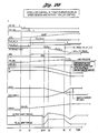
- FIGs 17 and 18 show the logic and the execution of this calibration option during the shift interval.
- Execution of a 2-3 upshift is a sequence of events and control actions with interacting activities between the control strategy and the control hardware.
- the timing diagram shown in Figure 18 represents the execution of a 2-3 upshift. Control strategy as well as the hardware executing actions are illustrated in this timing diagram.
- the shift verification timer TM_VER_SFT is expired and the gear commanded register GR_CM is changed from 2 nd to 3 rd gear.
- RT_SFT_END GRRAT2 + [FNPCSFT23(TP_REL) * (GRRAT3 - GRRAT2)]
- RT_23_TRIG GRRAT2 + [FN23CMPF(NOBART)*(GRRAT3 - GRRAT2)]
- the gear ratio threshold value RT_23_TRIG is calculated based on the function FN23CMPF, percentage shift complete PCSFTCMPT versus output shaft speed NOBART in order to determine the start of open loop capacity control of the overdrive band, executed by the shift solenoid 4 duty cycle SS4 DC.
- a further gear ratio threshold value RT_SFT_END is calculated to determine the end of open loop capacity control and to release the overdrive band capacity completely. These values are compared later with the continuously calculated RT_TRANS and are used for the above described functions.
- Shift solenoid flag 2 FLG_SS_2 is set to 1 and the EPC-RMP timer is loaded. The EPC ramp is now executed.
- An initial duty cycle of shift solenoid 4 is loaded into the SS4_DC register. This initial duty cycle is required to pre-fill the overdrive servo release side prior to shift execution.
- the 2-3 upshift start timer TM_23_STRT is loaded. This timer is required to initiate a start duty cycle independently of the expiration of the shift verification timer TM_VER_SFT. When this timer is expired, a start duty cycle is set prior to open loop capacity control of the overdrive band.
- the TM_23_STRT timer is a function of transmission oil temperature since the applied pressure varies with duty cycle and temperature.
- the total overdrive torque consisting of TQ_I ⁇ _SIMP and static brake torque has reached a level which exceeds the overdrive band capacity.
- the overdrive drum speed starts to rise.
- the SS4 duty cycle is kept unchanged.
- SS4_DC_BRK is commanded on the release side of the overdrive servo.
- SS4_DC SS4_DC_BRK + SS4_DC_RMP (PCSFTCMPT)
- the SS4_DC_RMP can be a function of percentage shift complete PCSFTCMPT in order to be able to synchronise the termination of the ramp with the completion of the shift.
- the overdrive servo release pressure is either increased or kept constant based on the SS4 duty cycle.
- the overdrive band capacity is controlled by commanding additional overdrive band slip. Independent open loop control of the overdrive planetary gearset is initiated. The output shaft torque decreases since the capacity on the overdrive band is decreased as well.
- the RT_TRANS value is smaller than the second ratio threshold RT_SFT_END.
- the open loop control of the overdrive band is terminated by setting the shift solenoid flag 3 FLG_SS_3 to 0.
- the shift solenoid 4 duty cycle calculations are still kept high. This is the synchronisation point between the downshifting of the overdrive planetary gearset and the upshifting of the Simpson gearset.
- the timer SS4_END_TMR is loaded and SS4_DC is high.
- the timer is needed to compensate for the SS3 pressure exhaust delay time.
- Shift solenoid 3(SS3) is de-energised and the 3-4 upshift valve moves into downshift position.
- the shift solenoid 4 (SS4) output pressure is disconnected from the overdrive servo release side and is connected to line pressure. This reduces the overdrive band capacity completely and OWC1 takes the remaining inertia and begins to transmit full torque.
- the output pressure of the shift solenoid 4 is kept high in order to keep the overdrive servo release area pressurised.
- downshift accumulation takes place at the overdrive planetary gearset in order to accomplish a smooth one-way clutch engagement of OWC1.
- This accumulation phase is also used to synchronise the downshifting of the overdrive planetary gearset and the upshifting of the Simpson set using open loop control.
- the hatched area of the overdrive servo release area indicates the time where independent capacity control takes place between the overdrive gearset and the Simpson set.
- the overdrive servo release pressure is line pressure.
- the output shaft torque characteristic has negative slope since the overdrive band has zero capacity.
- the flow diagram in Figure 17 shows the control strategy during a 2-3 upshift. It summarises the 2-3 upshift execution explained above.
- Option 3 (This option is without the Overdrive Drum Speed Sensor and without cycling Shift Solenoid 4 and is Open Loop controlled)
- FIGS. 19 and 20 show the logic and execution of this calibration option.
- This control method requires the opening of orifice 74 and the closing orifice 76 (see Figures 9, lla and 12a). This disconnects the overdrive servo release side from shift solenoid 4 and connects the OSR side over the shift valve in bore 212 to the CL1/B1/EX exhaust port.
- This option is explained in U.S. application Serial No. 08/549,438, filed October 27, 1995, which was identified previously.
- the execution of a 2-3 upshift is a sequence of events and control actions with interaction between the control strategy and the control hardware.
- the timing diagram shown in Figure 20 shows the execution of a 2-3 upshift. Control strategy as well as hardware execution are illustrated in this timing diagram.
- the driver desires a 2-3 upshift, which is triggered by the control strategy based on functions of vehicle speed versus throttle position.
- the GR DS register is changed from 2 nd gear to 3 rd gear and the shift verification timer TM_VER_SFT is loaded.
- the dynamic EPC value is added for third gear.
- the EPC values are increased according to the commanded EPC values.
- the overdrive servo release is exhausted over the CL1/B1/Ex exhaust port.
- the shift verification timer TM_VER_SFT is expired and the gear commanded register GR_CM is changed from 2 nd to 3 rd gear.
- the gear ratio threshold value RT_SFT_END is calculated to determine when to turn off shift solenoid 3 and when to release the overdrive band capacity completely. These values are compared later with the continuously calculated RT_TRANS and are used for the functions above described.
- Shift solenoid flag 2 FLG_SS_2 is set to 1 and the EPC-RMP timer is loaded. The EPC ramp then is executed.
- Shift solenoid 2 is energised and the 1-2 upshift valve in bore 203 moves into upshift position.
- CF pressure produced from the clutch pressure modulator forward in bore 207 is applied to the intermediate servo apply side.
- the characteristic of this forward modulator allows capacity control from zero to maximum capacity.
- the intermediate band engages and takes the torque of the sun gear from the Simpson planetary gearset.
- the reaction torque on OWC2 is reduced.
- the output shaft torque follows first the reaction torque characteristic from OWC2. The torque phase of the 2-3 swap shift is initiated.
- the torque phase of the upshifting Simpson planetary gearset is initiated.
- the RT_TRANS value is calculated continuously based on turbine speed and output shaft speed.
- the RT_TRANS value starts to decrease since the inertia phase of the 2-3 upshift is started and the torque phase is completed.
- the shift starts with shift slope 1, which is entirely dependent on the CF pressure settings and the commanded EPC ramp.
- the torque phase of the upshifting event for the Simpson planetary gearset is completed and the output shaft torque is completely dependent on the applied capacity of the intermediate band.
- the reaction torque on one-way clutch OWC2 is zero and the high clutch drum speed (HCDS) starts to decelerate.
- the output shaft torque is reversed since the reaction torque is zero and ISA pressure is increasing.
- the inertia phase of the Simpson planetary gearset is initiated.
- the TQ_I ⁇ _SIMP which is the reaction torque of the inertia torque of the Simpson set, increases.
- the total Overdrive torque consisting of TQ_I ⁇ _SIMP and static brake torque has reached a level which exceeds the overdrive band capacity.
- the overdrive drum speed starts to rise. Shift slope 2 is initiated depending on how high the overdrive brake band capacity B1 is set.
- Shift solenoid flag FLG_SS_3 is set to zero.
- Shift solenoid 3(SS3) is de-energised and the 3-4 upshift valve moves into downshift position.
- the CL1/B1/Ex port is disconnected from the overdrive servo release side and line pressure is connected. This reduces the overdrive band capacity completely and OWC1 takes the remaining inertia and starts to transmit full torque.
- the overdrive servo release pressure is line pressure.
- the output shaft torque characteristic has another negative slope since the overdrive band has zero capacity.
- the EPC_RMP timer has expired and the EPC ramp is terminated.
- the overdrive drum speed has reached engine speed and the OWC1 is fully engaged.
- the high clutch drum speed (HCDS) is zero and so is TQ I ⁇ _SIMP.
- the output shaft torque characteristic is now reversed again since the OWC1 carries full torque.
- the torque phase of the downshifting event is initiated and the 2-3 upshift is complete.
- Line pressure is connected to the overdrive servo release chamber. This is the synchronisation point for the downshifting overdrive gearset and the upshifting Simpson set within a given calibration window.
- the flow diagram of Figure 19 shows the control strategy during a 2-3 upshift. It is a summary of the 2-3 upshift execution explained above.
Abstract
Description
| FIVE-SPEED TRANSMISSION | FOUR-SPEED TRANSMISSION | |||
| GEAR | GEAR RATIO | | GEAR RATIO | |
| 1ST | 2.474 | 1ST | 2.474 | |
| 2ND | 1.855 | --- | --- | |
| 3RD | 1.474 | 2ND | 1.474 | |
| 4TH | 1.0 | 3RD | 1.0 | |
| 5TH | 0.75 | 4TH | 0.75 |
OCS, TP
VSS, TSS, MLP, TOT, ODS, OSS
N, MAF
- 3 ON/OFF solenoids for shifts (SS1-SS3)
- 1 VFS for clutch capacity
- SS4 for overdrive band capacity control, which may be a duty-cycled ON/OFF solenoid.
| SHIFTS | SYNCHRONOUS | |
| 2- | Reaction-to-Reaction (B1/OWC1 to B2/OWC2) | |
| 3 | ||
| 3- | Reaction-to-Reaction (B2/OWC2 TO B1/OWC1) | |
| 2 | ||
| 4- | Drive-to-Reaction (CL2 to B1/OWC1) | |
| 2 |
- B1 capacity has to be controlled electronically,
- B2 capacity has to be controlled electronically,
- B1 and B2 have to be controlled independently,
- The electronically controlled B1 and B2 characteristics have to be able to control capacity with regard to OWC1 and OWC2 engagement quality,
- Turbine speed has to be monitored,
- OWC1 acceleration and deceleration has to be monitored by sensing CL1 speed, which is overdrive drum speed, and
- Electronic control of upshift and downshift execution.
- minimum detectable signal: 150 RPM with ± 340 mV amplitude,
- maximum signal allowed: 7000 RPM ± 90 V amplitude,
- For noise immunity, the
sensor 56 needs a separate signal wire to the EEC module.
- minimum detectable signal: 150 RPM with ± 340 mV amplitude,
- maximum signal allowed: 7000 RPM with ± 90 V amplitude;
- for noise immunity, the
sensor 56 needs a separate signal wire to the EEC module.
- PCSFTCMPT = percentage shift complete
This calculates the percentage of the gear ratio
depending on the old gear and the command gear
- RT_TRANS = current calculated gear ratio
- GRRAT = gear ratio in each gear
- GR_CM = commanded gear
- GR_OLD = old gear
- RT_TRANS = instantaneous calculated gear ratio
- RT_TRANS = NT/NO
- NT = turbine speed
- NO = output shaft speed Additional further important calculations are added which are specific to the 2-3 upshift execution. These are:
- RT_SFT_END = The transmission ratio where the shift
solenoid stages are controlled.
This calculation is used to determine, based on
calibration data, the transmission gear ratio threshold
when the solenoid stages should be changed from the
intermediate step 3 (IS3) to third gear.
- GRRAT2 = gear ratio in 2nd gear
- GRRAT3 = gear ratio in 3rd gear
- FNPCSFT23(TP_REL) =
- function TP_REL versus PCSFTCMPT to determine the percentage shift complete value when the solenoid stages change
- TP_REL =
- relative throttle position
- RT_23_TRIG = ratio threshold when capacity control by
shift solenoid 58 (SS4) takes place
- FN23CMPF =
- function NOBART versus PCSFTCMPT to determine the percentage shift complete value when capacity control on the overdrive band should take place
- NOBART =
- output shaft speed
- ODS_TRG = target overdrive drum speed
ODS_TRG = NOBART*GRRAT3*FNODS_CMPT(NOBART) This calculates the overdrive drum speed target based on the output shaft speed NOBART and a function NOBART versus a multiplier
FNODS_CMPT(NOBART) = function NOBART versus a multiplier to determine the target overdrive drum speed - ODSS_TRG_FG = target overdrive drum speed dependent on
the gear ratio
This calculates the target overdrive drum speed as a
function depending on actual gear ratio RT TRANS. The
target overdrive drum speed ODSS_TRG is increased and
synchronised with the execution of the shift.
- valve body and connecting labyrinth 62 (see Figure 1),
- 3 ON/OFF solenoids,
-
SS4 shift solenoid 58, - 1 main regulator valve 68 (includes a booster valve),
- 2 modulator valves,
- 5 shift valves,
- 1
variable force solenoid 66, - 1 separator plate with connecting holes, and
- springs and sleeves.
- Electronic pressure control with VFS
- EPCB boost pressure system
- SS4 pressure system (PWM-pressure)
- Main regulator valve system (PL)
- SOL1, SOL2 regulator valve system
- Clutch pressure modulator forward (CF).
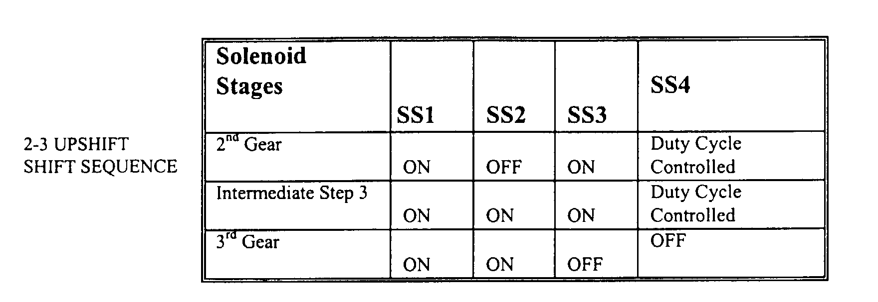
- GR-DS desired gear,
- GR-CM commanded gear,
- EPC control pressure register,
- FLG_SS_1
shift solenoid flag 1 - FLG_SS_2
shift solenoid flag 2, - FLG_SS_3
shift solenoid flag 3, - RT_TRANS calculated gear ratio,
-
SS4_DC shift solenoid 4 duty cycle, - TM_23_STRT timer to enable start duty cycle,
- ODS overdrive drum speed,
- N engine speed,
- NT turbine speed,
- NOBART output shaft speed,
- SS1
shift solenoid pressure 1, - SS2
shift solenoid pressure 2, - SS3
shift solenoid pressure 3, - OSA overdrive servo apply pressure,
- OSR overdrive servo release pressure,
- ISA intermediate servo apply pressure,
- HCDS high clutch drum (CL2) speed (not calculated by control strategy), and
- Output shaft torque.
OL_CORR is a calibration constant to determine the gain of duty cycles change.
ODSS_TRG_FG is the overdrive drum speed target value depending on the actual gear ratio.

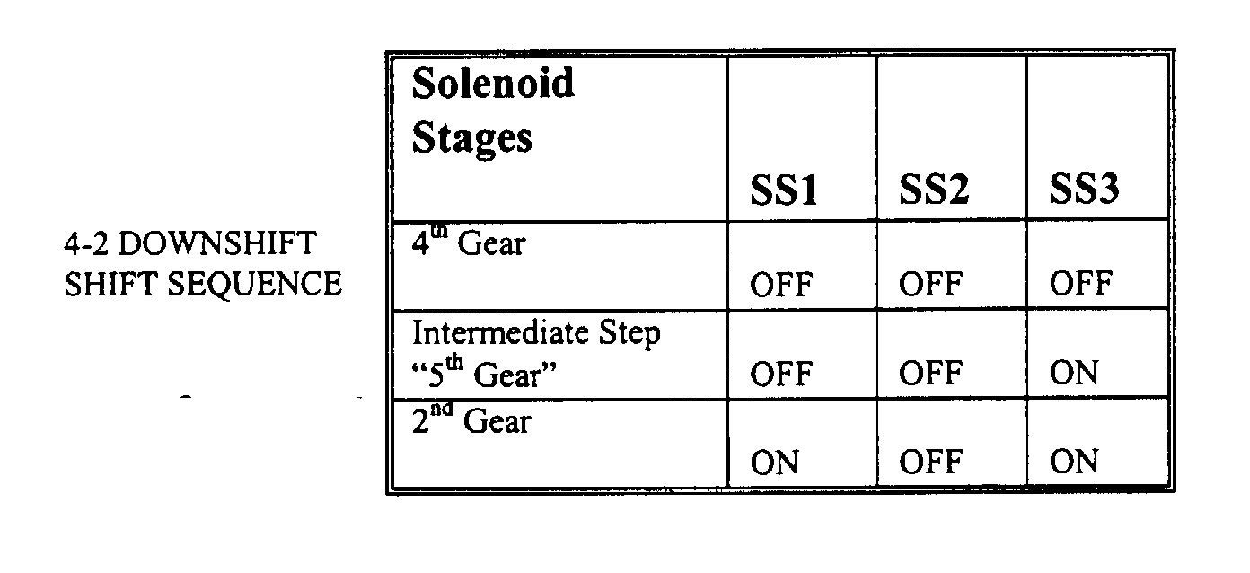
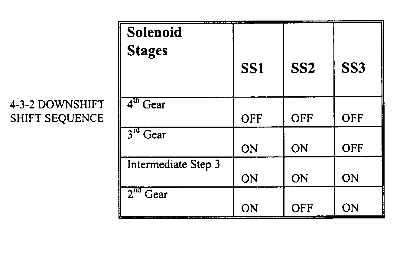
- GR_DS desired gear
- GR_CM commanded gear
- EPC control pressure register
- FLG_SS_1
shift solenoid flag 1 - FLG_SS_2
shift solenoid flag 2 - FLG_SS_3
shift solenoid flag 3 - ODS overdrive drum speed
- N engine speed
- NT turbine speed
- SS1
shift solenoid pressure 1 - SS2
shift solenoid pressure 2 - SS3
shift solenoid pressure 3 - OSA overdrive servo apply pressure
- OSR overdrive servo release pressure
- ISA intermediate servo apply pressure
- HCDS-high clutch drum speed (not calculated by control strategy)
- Output shaft torque.
- GR_DS desired gear
- GR_CM commanded gear
- EPC control pressure register
-
FLG SS 1shift solenoid flag 1 - FLG_SS_2
shift solenoid flag 2 - FLG_SS_3
shift solenoid flag 3 - RT_TRANS calculated gear ratio
-
SS4_DC shift solenoid 4 duty cycle - TM_23_STRT timer to enable start duty cycle
- ODS overdrive drum speed
- N engine speed
- NT turbine speed
- ODS_TRG_FG overdrive drum speed target value
- SS1
shift solenoid pressure 1 - SS2
shift solenoid pressure 2 - SS3
shift solenoid pressure 3 - OSA overdrive servo apply pressure
- OSR overdrive servo release pressure
- ISA intermediate servo apply pressure
- HCDS high clutch drum speed (not calculated by control strategy)
- Output shaft torque
- TQ_Iα_SIMP additional inertia torque imparted by the Simpson planetary gearset to the overdrive planetary gearset.
Claims (12)
- An automatic transmission for a vehicle having gearing defining multiple torque flow paths between a throttle controlled engine and a torque output shaft comprising a first gear unit with at least three forward-driving ratios and a second gear unit with at least two forward driving ratios, said gear units being disposed in series relationship in said torque flow paths, said torque flow paths including a torque converter with an impeller driven by said engine and a turbine connected drivably to said second gear unit;pressure operated clutch and brake means for establishing and disestablishing ratio changes in said gearing including a first reaction brake means for anchoring a reaction element of said first gear unit during operation in an intermediate ratio of said first gear unit and a second reaction brake means for anchoring a reaction element of said second gear unit during operation in the higher of said two forward driving ratios of said second gear unit;said first reaction brake means including a first brake servo having a first servo piston and brake release and apply pressure chambers on opposite sides of said first servo piston;said second reaction brake means including a second brake servo having a second servo piston and brake release and apply pressure chambers on opposite sides of said second brake servo piston;a control valve system for controlling distribution of pressure to said clutch and brake means including said apply pressure chambers for said first and second brake servos and to said release pressure chamber for said second brake servo, said valve system including a source of line pressure and a main pressure regulator valve means for regulating said line pressure;electronic pressure control means communicating with said main pressure regulator valve means for establishing a control pressure determined by operating variables including vehicle speed, turbine speed and engine throttle position, an electronic control pressure passage communicating with said electronic pressure control means;first pressure modulator valve means in said control valve system for establishing a first modulated control pressure including a pressure area in communication with said electronic control pressure passage;second pressure modulator valve means in said control system for establishing a second modulated control pressure;said valve system including ratio shift control valve means for providing controlled communication between said apply pressure chambers of said first and second brake servos and said first pressure modulator valve means and between said release pressure chamber of said second brake servo and said second pressure modulator valve means whereby brake capacities during application and release of said first and second reaction brake means are controlled independently,said valve system also including means for reducing braking capacity of said second reaction brake means to a marginal value sufficient to prevent brake slip at inception of a ratio change to said lower of said two forward driving ratios for said second gear unit during a ratio change of said first gear unit to a higher ratio than said intermediate ratio of said first gear unit.
- An automatic transmission for a vehicle having gearing defining multiple torque flow paths between a throttle controlled engine and a torque output shaft comprising a first gear unit with at least three forward-driving ratios and a second gear unit with at least two forward driving ratios, said gear units being disposed in series relationship in said torque flow paths, said torque flow paths including a torque converter with an impeller driven by said engine and a turbine connected drivably to said second gear unit;pressure operated clutch and brake means for establishing and disestablishing ratio changes in said gearing including a first reaction brake means for anchoring a reaction element of said first gear unit during operation in an intermediate ratio of said first gear unit and a second reaction brake means for anchoring a reaction element of said second gear unit during operation in the higher of said two forward driving ratios of said second gear unit;said first reaction brake means including a first brake servo having a first servo piston and brake release and apply pressure chambers on opposite sides of said first servo piston;said second reaction brake means including a second brake servo having a second servo piston and brake release and apply pressure chambers on opposite sides of said second brake servo piston;a control valve system for controlling distribution of pressure to said clutch and brake means including said apply pressure chambers for said first and second brake servos and to said release pressure chamber for said second brake servo, said valve system including a source of line pressure and a main pressure regulator valve means for regulating said line pressure;electronic pressure control means communicating with said main pressure regulator valve means for establishing a control pressure determined by operating variables including vehicle speed, turbine speed and engine throttle position, an electronic control pressure passage communicating with said electronic pressure control means;first pressure modulator valve means in said control valve system for establishing a first modulated control pressure including a pressure area in communication with said electronic control pressure passage;second pressure modulator valve means in said control system for establishing a second modulated control pressure;said valve system including ratio shift control valve means for providing controlled communication between said apply pressure chambers of said first and second brake servos and said first pressure modulator valve means and between said release pressure chamber of said second brake servo and said second pressure modulator valve means whereby brake capacities during application and release of said first and second reaction brake means are controlled independently,said valve system also including means for increasing pressure in said release pressure chamber for said second brake servo to a value that establishes marginal braking of said reaction element of said second gear unit at inception of a ratio change to said lower of said two forward driving ratios for said second gear unit during a ratio change of said first gear unit to a higher ratio than said intermediate ratio of said first gear unit upon an upshift of said automatic transmission.
- An automatic transmission as claimed in claim 2, wherein said first gear unit has a low ratio element in addition to said reaction element for said reaction brake means and clutch means for establishing unitary drive ratio in said first gear unit;said second gear unit being a simple planetary overdrive gear unit, said reaction element of said second gear unit being a sun gear, and a simple planetary gear unit clutch means for establishing unitary drive ratio in said second gear unit;said electronic pressure control means including an electronic processor, a first speed sensor means for detecting a speed that is functionally related to the speed of said reaction element of said second gear unit and a second speed sensor for detecting output shaft speed, and a third speed sensor for detecting turbine speed;means for computing inertia torque of said first gear unit during a ratio change of said automatic transmission from an intermediate ratio to a higher ratio, an increase of said inertia torque at the beginning of an inertia phase of said first gear unit following initiation of said ratio change, said processor including means for sensing said increase in inertia torque and initiating a reduction in said braking capacity of said second reaction brake means thereby triggering the start of the inertia phase of said second gear unit upon an upshift of said automatic transmission.
- An automatic transmission as claimed in claim 3, wherein said valve system includes means for increasing pressure in said release pressure chamber for said second brake servo to a value that establishes said marginal braking capacity of said reaction element of said second gear unit at inception of said ratio change to said lower of said two forward driving ratios for said second gear unit.
- An automatic transmission as claimed in claim 3, wherein said first speed sensor produces a speed signal corresponding to the speed of said reaction element of said second gear unit;
said processor including means responding to said speed signal to effect changes in braking capacity of said second brake servo in a closed loop manner whereby synchronization of downshifting of said second gear unit and upshifting of said first gear unit is achieved. - An automatic transmission as claimed in claim 3, wherein said second and third speed sensors develop output shaft speed signals and turbine speed signals respectively, said processor including means responding to changes in such output shaft and turbine speed signals for changing braking capacity of said second brake servo in an open loop manner, the change in said braking capacity being related functionally to percentage of shift completion manner whereby synchronization of downshifts of said second gear unit and upshift of said first gear unit is achieved.
- An automatic transmission as claimed in claim 6, wherein said control valve system includes a duty cycle controlled pressure regulator valve means for varying pressure distributed to said second brake servo;
said processor including means for varying said duty cycle whereby said braking capacity of said second brake servo is increased during downshifting of said second gear unit. - An automatic transmission as claimed in claim 5, wherein said processor includes means for calculating a target reaction element speed for said second gear unit, said processor responding to said target reaction element speed to effect said closed loop braking capacity control during said synchronization of said downshifting of said second gear unit and upshifting of said first gear unit.
- An automatic transmission for a vehicle having gearing defining multiple torque flow paths between a throttle controlled engine and a torque output shaft comprising a first gear unit with at least three forward-driving ratios and a second gear unit with at least two forward driving ratios, said gear units being disposed in series relationship in said torque flow paths, said torque flow paths including a torque converter with an impeller driven by said engine and a turbine connected drivably to said second gear unit;pressure operated clutch and brake means for establishing and disestablishing ratio changes in said gearing including a first reaction brake means for anchoring a reaction element of said first gear unit during operation in an intermediate ratio of said first gear unit and a second reaction brake means for anchoring a reaction element of said second gear unit during operation in the higher of said two forward driving ratios of said second gear unit;said first reaction brake means including a first brake servo having a first servo piston and brake release and apply pressure chambers on opposite sides of said first servo piston;said second reaction brake means including a second brake servo having a second servo piston and brake release and apply pressure chambers on opposite sides of said second brake servo piston;a control valve system for controlling distribution of pressure to said clutch and brake means including said apply pressure chambers for said first and second brake servos and to said release pressure chamber for said second brake servo, said valve system including a source of line pressure and a main pressure regulator valve means for regulating said line pressure;electronic pressure control means communicating with said main pressure regulator valve means for establishing a control pressure determined by operating variables including vehicle speed, turbine speed and engine throttle position, an electronic control pressure passage communicating with said electronic pressure control means;first pressure modulator valve means in said control valve system for establishing a first modulated control pressure including a pressure area in communication with said electronic control pressure passage;second pressure modulator valve means in said control system for establishing a second modulated control pressure;said valve system including ratio shift control valve means for providing controlled communication between said apply pressure chambers of said first and second brake servos and said first pressure modulator valve means and between said release pressure chamber of said second brake servo and said second pressure modulator valve means whereby brake capacities during application and release of said first and second reaction brake means are controlled independently;said electronic pressure control means including an electronic processor, a first speed sensor means for detecting a speed value of said reaction element of said second gear unit, a second speed sensor means for detecting a speed value that is functionally related to output shaft speed, and a third speed sensor for detecting a turbine speed value;said electronic processor responding to values detected by said sensors for said second gear unit reaction element speed, said speed that is functionally related to output shaft speed and said turbine speed to develop a value for said control pressure that effects said independent brake capacity control of said first and second reaction brake means during said upshifts and downshifts;said electronic processor including means for detecting the start of the inertia phase of the upshifting of said first gear unit whereby the initiation of the downshifting of said second gear unit is triggered by said start of the inertia phase of the upshifting of said first gear unit.
- An automatic transmission as claimed in claim 9, wherein said means for detecting upshifting of said first gear unit responds to said second and third speed values to trigger activation of said second brake servo, said actuation of said second brake servo being an open loop pressure control of pressure on said brake release chamber of said second brake servo.
- An automatic transmission as claimed in claim 9, wherein said electronic processor includes means for calculating percentage of shift completion during an upshift to said higher of said two forward driving ratios, said electronic processor pressure control responding to changes in said percentage of shift completion in an open loop manner to increase pressure applied to said second brake servo during said upshift.
- An automatic transmission as claimed in claim 9, wherein said electronic pressure control includes a duty cycled pressure regulator value means responsive to changes in said speed values of said reaction element for establishing in an open loop fashion an initial duty cycle pressure at the beginning of said upshifting of said first gear unit thereby establishing an initial slip valve of said second reaction brake means.
Applications Claiming Priority (2)
| Application Number | Priority Date | Filing Date | Title |
|---|---|---|---|
| US08/681,232 US5809442A (en) | 1995-10-27 | 1996-07-22 | Multiple ratio transmission having swap-shift controls with optimum ratio upshifts |
| US681232 | 1996-07-22 |
Publications (3)
| Publication Number | Publication Date |
|---|---|
| EP0821189A2 true EP0821189A2 (en) | 1998-01-28 |
| EP0821189A3 EP0821189A3 (en) | 1998-07-29 |
| EP0821189B1 EP0821189B1 (en) | 2001-08-22 |
Family
ID=24734374
Family Applications (1)
| Application Number | Title | Priority Date | Filing Date |
|---|---|---|---|
| EP97305448A Expired - Lifetime EP0821189B1 (en) | 1996-07-22 | 1997-07-21 | Multiple ratio transmission with swap-shift controls |
Country Status (3)
| Country | Link |
|---|---|
| US (1) | US5809442A (en) |
| EP (1) | EP0821189B1 (en) |
| DE (1) | DE69706251T2 (en) |
Cited By (1)
| Publication number | Priority date | Publication date | Assignee | Title |
|---|---|---|---|---|
| EP1906061A3 (en) * | 2006-09-29 | 2010-07-07 | Chrysler Group LLC | Transmission downshift control method |
Families Citing this family (20)
| Publication number | Priority date | Publication date | Assignee | Title |
|---|---|---|---|---|
| JP3211697B2 (en) * | 1997-02-10 | 2001-09-25 | 日産自動車株式会社 | Target transmission ratio generation device for continuously variable transmission |
| KR100331645B1 (en) * | 1999-11-16 | 2002-04-09 | 이계안 | Method for controlling a run up of automatic transmission |
| US6254510B1 (en) * | 2000-03-22 | 2001-07-03 | Ford Global Technologies, Inc. | Coasting downshift control strategy for a multiple-ratio automatic transmission |
| US6301538B1 (en) | 2000-06-07 | 2001-10-09 | Ford Global Technologies, Inc. | Swap shift multiple-ratio automatic transmission |
| US6278926B1 (en) | 2000-09-18 | 2001-08-21 | Ford Global Technologies, Inc. | Adaptive electronic transmission control system and strategy for nonsynchronous automatic transmission |
| US6449548B1 (en) | 2001-02-14 | 2002-09-10 | Ford Global Technologies, Inc. | Automatic transmission shift control |
| US6471616B2 (en) * | 2001-02-15 | 2002-10-29 | General Motors Corporation | Power transmission with friction launch torque transmitting mechanism in forward and reverse |
| US6549838B2 (en) | 2001-05-21 | 2003-04-15 | Ford Global Technologies, Inc. | High energy engagement strategy for automatic transmission clutches and brakes |
| US6370463B1 (en) | 2001-11-01 | 2002-04-09 | Ford Global Technologies, Inc. | Strategy for controlling ratio changes in a swap-shift automatic transmission |
| DE10231820A1 (en) * | 2002-07-15 | 2004-02-05 | Zf Friedrichshafen Ag | Method for determining the parameters of a transmission |
| DE10327543B4 (en) * | 2002-09-05 | 2012-11-15 | Hyundai Motor Co. | Shift control method for an automatic transmission |
| US7107135B2 (en) * | 2003-10-31 | 2006-09-12 | Ford Global Technologies, Llc | Auxiliary gearset shift progression command generator for a swap-shift automatic transmission |
| US6961646B2 (en) * | 2003-10-31 | 2005-11-01 | Ford Global Technologies, Llc | Automatic transmission control system with direct electronic swap-shift control |
| TWI375628B (en) * | 2004-08-20 | 2012-11-01 | Dsi Holdings Pty Ltd | Transmission |
| AU2005274690B2 (en) * | 2004-08-20 | 2012-06-07 | Dsi Holdings Pty Limited | Multi-ratio automatic transmission with independent rate of engagement and/or disengagement control of friction elements |
| US7912617B2 (en) * | 2005-12-14 | 2011-03-22 | Gm Global Technology Operations, Inc. | Air purge method for a rotating clutch |
| JP4257350B2 (en) * | 2006-07-31 | 2009-04-22 | ジヤトコ株式会社 | Control device and method for automatic transmission |
| US7789798B2 (en) * | 2006-09-27 | 2010-09-07 | Chrysler Group Llc | Transmission upshift control method |
| US7632215B2 (en) * | 2006-12-05 | 2009-12-15 | Chrysler Group Llc | Transmission downshift swap-shift control |
| JP2009236262A (en) * | 2008-03-28 | 2009-10-15 | Aisin Aw Co Ltd | Shift control device for automatic transmission |
Citations (4)
| Publication number | Priority date | Publication date | Assignee | Title |
|---|---|---|---|---|
| US5168776A (en) * | 1990-02-05 | 1992-12-08 | Toyota Jidosha Kabushiki Kaisha | Shift control system and method for automatic transmissions |
| EP0565111A2 (en) * | 1992-04-10 | 1993-10-13 | Mazda Motor Corporation | Multiple stage automatic transmission |
| EP0707164A2 (en) * | 1994-10-14 | 1996-04-17 | Ford Motor Company Limited | Shift control system for a multiple ratio automatic transmission |
| EP0707162A2 (en) * | 1994-10-14 | 1996-04-17 | Ford Motor Company Limited | Multiple ratio automatic transmission and control system |
Family Cites Families (16)
| Publication number | Priority date | Publication date | Assignee | Title |
|---|---|---|---|---|
| US4007648A (en) * | 1975-04-24 | 1977-02-15 | Ford Motor Company | Five-speed automatic transmission |
| JPS61241558A (en) * | 1985-04-18 | 1986-10-27 | Toyota Motor Corp | Method of controlling speed change of automatic transmission for vehicle |
| US4653350A (en) * | 1985-11-29 | 1987-03-31 | General Motors Corporation | Adaptive direct pressure shift control for a motor vehicle transmission |
| JPS62165051A (en) * | 1986-01-13 | 1987-07-21 | Toyota Motor Corp | Method for controlling automatic transmission |
| JP2696819B2 (en) * | 1986-10-08 | 1998-01-14 | 日産自動車株式会社 | Shift shock reduction device for automatic transmission |
| JPH0621620B2 (en) * | 1987-07-28 | 1994-03-23 | 日産自動車株式会社 | Gearbox of automatic transmission |
| US4884471A (en) * | 1988-06-23 | 1989-12-05 | Ford Motor Company | Four speed ratio automatic power transmission |
| US5176592A (en) * | 1989-01-23 | 1993-01-05 | Toyota Jidosha Kabushiki Kaisha | Speed changing gear device having two independent gear assemblies |
| JP2739121B2 (en) * | 1989-09-05 | 1998-04-08 | トヨタ自動車株式会社 | Transmission control device for automatic transmission |
| JP2966003B2 (en) * | 1989-09-06 | 1999-10-25 | トヨタ自動車株式会社 | Transmission control device for automatic transmission |
| DE3931025A1 (en) * | 1989-09-16 | 1991-03-28 | Porsche Ag | AUTOMATIC TRANSMISSION FOR A MOTOR VEHICLE |
| US5070747A (en) * | 1989-12-26 | 1991-12-10 | General Motors Corporation | Adaptive powered downshift control of an automatic transmission |
| US5334117A (en) * | 1990-09-28 | 1994-08-02 | Mazda Motor Corporation | Automatic transmission with an add-on extension to increase the number of gear ratios |
| US5224907A (en) * | 1990-09-28 | 1993-07-06 | Jatco Corporation | Automatic transmission |
| US5167592A (en) * | 1991-05-10 | 1992-12-01 | Jatco Corporation | Automatic transmission |
| JPH0587230A (en) * | 1991-09-25 | 1993-04-06 | Mazda Motor Corp | Shift controller of automatic transmission |
-
1996
- 1996-07-22 US US08/681,232 patent/US5809442A/en not_active Expired - Lifetime
-
1997
- 1997-07-21 DE DE69706251T patent/DE69706251T2/en not_active Expired - Lifetime
- 1997-07-21 EP EP97305448A patent/EP0821189B1/en not_active Expired - Lifetime
Patent Citations (4)
| Publication number | Priority date | Publication date | Assignee | Title |
|---|---|---|---|---|
| US5168776A (en) * | 1990-02-05 | 1992-12-08 | Toyota Jidosha Kabushiki Kaisha | Shift control system and method for automatic transmissions |
| EP0565111A2 (en) * | 1992-04-10 | 1993-10-13 | Mazda Motor Corporation | Multiple stage automatic transmission |
| EP0707164A2 (en) * | 1994-10-14 | 1996-04-17 | Ford Motor Company Limited | Shift control system for a multiple ratio automatic transmission |
| EP0707162A2 (en) * | 1994-10-14 | 1996-04-17 | Ford Motor Company Limited | Multiple ratio automatic transmission and control system |
Cited By (1)
| Publication number | Priority date | Publication date | Assignee | Title |
|---|---|---|---|---|
| EP1906061A3 (en) * | 2006-09-29 | 2010-07-07 | Chrysler Group LLC | Transmission downshift control method |
Also Published As
| Publication number | Publication date |
|---|---|
| US5809442A (en) | 1998-09-15 |
| DE69706251D1 (en) | 2001-09-27 |
| DE69706251T2 (en) | 2002-01-10 |
| EP0821189A3 (en) | 1998-07-29 |
| EP0821189B1 (en) | 2001-08-22 |
Similar Documents
| Publication | Publication Date | Title |
|---|---|---|
| EP0770800B1 (en) | An automatic transmission | |
| EP0821189B1 (en) | Multiple ratio transmission with swap-shift controls | |
| EP0825366B1 (en) | Swap-shift control system for a multiple ratio transmission | |
| EP0707164B1 (en) | Shift control system for a multiple ratio automatic transmission | |
| US5157608A (en) | Electronic control system for multiple ratio transmission including circuit pressure control | |
| US5046383A (en) | Acceleration-based control of power-on clutch-to-clutch upshifting in an automatic transmission | |
| EP0322111B1 (en) | Event sequenced clutch-to-clutch downshift for an electronically controlled automatic transmission | |
| EP0436978B1 (en) | Method of controlling gear changes in an automatic transmission | |
| US5303616A (en) | Electronically controlled bypass clutch based on percent-shift-completion for a torque converter | |
| EP0978672B1 (en) | Control system for multiple ratio automatic transmission | |
| US5113343A (en) | Sequenced control of double transition powered downshifting in an automatic transmission | |
| US4989477A (en) | Double transition closed throttle downshift control in an automatic transmissions | |
| US6385520B1 (en) | Control strategy and method for independently controlling friction element actuators for an automatic transmission | |
| US5133227A (en) | Method of power-on downshifting of automatic transmission interrelated with temporary torque down of engine | |
| EP0707165B1 (en) | Multiple ratio automatic transmission and torque converter | |
| US6122583A (en) | Upshift and downshift control valve system for multiple ratio automatic transmission | |
| JP3540529B2 (en) | Hydraulic control device for automatic transmission | |
| US6370463B1 (en) | Strategy for controlling ratio changes in a swap-shift automatic transmission | |
| EP0707163B1 (en) | Shift control system for a multiple ratio automatic transmission with manual ratio ranges | |
| KR20020022023A (en) | Shift control apparatus for automatic transmission | |
| US5596495A (en) | Gearshift controller for automatic transmission | |
| US5704874A (en) | Shift control method for automatic transmission | |
| US4813307A (en) | Method of controlling hydraulic pressure for an automatic transmission gear system | |
| US6074319A (en) | Ratio change control system for multiple ratio transmission | |
| JP2537946B2 (en) | Torque converter slip control device |
Legal Events
| Date | Code | Title | Description |
|---|---|---|---|
| PUAI | Public reference made under article 153(3) epc to a published international application that has entered the european phase |
Free format text: ORIGINAL CODE: 0009012 |
|
| AK | Designated contracting states |
Kind code of ref document: A2 Designated state(s): DE FR GB |
|
| AX | Request for extension of the european patent |
Free format text: AL;LT;LV;RO;SI |
|
| PUAL | Search report despatched |
Free format text: ORIGINAL CODE: 0009013 |
|
| RHK1 | Main classification (correction) |
Ipc: F16H 61/06 |
|
| AK | Designated contracting states |
Kind code of ref document: A3 Designated state(s): AT BE CH DE DK ES FI FR GB GR IE IT LI LU MC NL PT SE |
|
| AX | Request for extension of the european patent |
Free format text: AL;LT;LV;RO;SI |
|
| 17P | Request for examination filed |
Effective date: 19981127 |
|
| AKX | Designation fees paid |
Free format text: DE FR GB |
|
| RBV | Designated contracting states (corrected) |
Designated state(s): DE FR GB |
|
| 17Q | First examination report despatched |
Effective date: 19991004 |
|
| GRAG | Despatch of communication of intention to grant |
Free format text: ORIGINAL CODE: EPIDOS AGRA |
|
| GRAG | Despatch of communication of intention to grant |
Free format text: ORIGINAL CODE: EPIDOS AGRA |
|
| GRAH | Despatch of communication of intention to grant a patent |
Free format text: ORIGINAL CODE: EPIDOS IGRA |
|
| GRAH | Despatch of communication of intention to grant a patent |
Free format text: ORIGINAL CODE: EPIDOS IGRA |
|
| GRAH | Despatch of communication of intention to grant a patent |
Free format text: ORIGINAL CODE: EPIDOS IGRA |
|
| GRAA | (expected) grant |
Free format text: ORIGINAL CODE: 0009210 |
|
| AK | Designated contracting states |
Kind code of ref document: B1 Designated state(s): DE FR GB |
|
| REF | Corresponds to: |
Ref document number: 69706251 Country of ref document: DE Date of ref document: 20010927 |
|
| REG | Reference to a national code |
Ref country code: GB Ref legal event code: IF02 |
|
| ET | Fr: translation filed | ||
| PLBE | No opposition filed within time limit |
Free format text: ORIGINAL CODE: 0009261 |
|
| STAA | Information on the status of an ep patent application or granted ep patent |
Free format text: STATUS: NO OPPOSITION FILED WITHIN TIME LIMIT |
|
| REG | Reference to a national code |
Ref country code: GB Ref legal event code: 746 Effective date: 20020619 |
|
| 26N | No opposition filed | ||
| REG | Reference to a national code |
Ref country code: GB Ref legal event code: 732E |
|
| REG | Reference to a national code |
Ref country code: FR Ref legal event code: D6 |
|
| REG | Reference to a national code |
Ref country code: FR Ref legal event code: TP |
|
| REG | Reference to a national code |
Ref country code: FR Ref legal event code: PLFP Year of fee payment: 20 |
|
| PGFP | Annual fee paid to national office [announced via postgrant information from national office to epo] |
Ref country code: GB Payment date: 20160624 Year of fee payment: 20 |
|
| PGFP | Annual fee paid to national office [announced via postgrant information from national office to epo] |
Ref country code: FR Payment date: 20160621 Year of fee payment: 20 |
|
| PGFP | Annual fee paid to national office [announced via postgrant information from national office to epo] |
Ref country code: DE Payment date: 20160801 Year of fee payment: 20 |
|
| REG | Reference to a national code |
Ref country code: DE Ref legal event code: R071 Ref document number: 69706251 Country of ref document: DE |
|
| REG | Reference to a national code |
Ref country code: GB Ref legal event code: PE20 Expiry date: 20170720 |
|
| PG25 | Lapsed in a contracting state [announced via postgrant information from national office to epo] |
Ref country code: GB Free format text: LAPSE BECAUSE OF EXPIRATION OF PROTECTION Effective date: 20170720 |