EP1905933A2 - Schiebetür zum Öffnen und Schließen von Zugängen und Verfahren zum Bewegen einer solchen Tür - Google Patents
Schiebetür zum Öffnen und Schließen von Zugängen und Verfahren zum Bewegen einer solchen Tür Download PDFInfo
- Publication number
- EP1905933A2 EP1905933A2 EP07116534A EP07116534A EP1905933A2 EP 1905933 A2 EP1905933 A2 EP 1905933A2 EP 07116534 A EP07116534 A EP 07116534A EP 07116534 A EP07116534 A EP 07116534A EP 1905933 A2 EP1905933 A2 EP 1905933A2
- Authority
- EP
- European Patent Office
- Prior art keywords
- door
- shutter
- frame
- intermediate frame
- coupled
- Prior art date
- Legal status (The legal status is an assumption and is not a legal conclusion. Google has not performed a legal analysis and makes no representation as to the accuracy of the status listed.)
- Withdrawn
Links
- 238000000034 method Methods 0.000 title claims description 25
- 239000002131 composite material Substances 0.000 claims description 6
- 238000001514 detection method Methods 0.000 claims description 6
- 239000000463 material Substances 0.000 claims description 5
- 230000005540 biological transmission Effects 0.000 claims description 4
- 230000003014 reinforcing effect Effects 0.000 claims description 3
- 238000005273 aeration Methods 0.000 description 3
- 238000009415 formwork Methods 0.000 description 3
- 230000008878 coupling Effects 0.000 description 2
- 238000010168 coupling process Methods 0.000 description 2
- 238000005859 coupling reaction Methods 0.000 description 2
- 239000013078 crystal Substances 0.000 description 2
- 239000011521 glass Substances 0.000 description 2
- 238000009434 installation Methods 0.000 description 2
- 241001544487 Macromiidae Species 0.000 description 1
- 239000004952 Polyamide Substances 0.000 description 1
- XAGFODPZIPBFFR-UHFFFAOYSA-N aluminium Chemical compound [Al] XAGFODPZIPBFFR-UHFFFAOYSA-N 0.000 description 1
- 229910052782 aluminium Inorganic materials 0.000 description 1
- 239000004411 aluminium Substances 0.000 description 1
- 238000009435 building construction Methods 0.000 description 1
- 238000010276 construction Methods 0.000 description 1
- 230000001419 dependent effect Effects 0.000 description 1
- 238000012986 modification Methods 0.000 description 1
- 230000004048 modification Effects 0.000 description 1
- 229920002647 polyamide Polymers 0.000 description 1
Images


Classifications
-
- B—PERFORMING OPERATIONS; TRANSPORTING
- B63—SHIPS OR OTHER WATERBORNE VESSELS; RELATED EQUIPMENT
- B63B—SHIPS OR OTHER WATERBORNE VESSELS; EQUIPMENT FOR SHIPPING
- B63B19/00—Arrangements or adaptations of ports, doors, windows, port-holes, or other openings or covers
-
- E—FIXED CONSTRUCTIONS
- E06—DOORS, WINDOWS, SHUTTERS, OR ROLLER BLINDS IN GENERAL; LADDERS
- E06B—FIXED OR MOVABLE CLOSURES FOR OPENINGS IN BUILDINGS, VEHICLES, FENCES OR LIKE ENCLOSURES IN GENERAL, e.g. DOORS, WINDOWS, BLINDS, GATES
- E06B3/00—Window sashes, door leaves, or like elements for closing wall or like openings; Layout of fixed or moving closures, e.g. windows in wall or like openings; Features of rigidly-mounted outer frames relating to the mounting of wing frames
- E06B3/32—Arrangements of wings characterised by the manner of movement; Arrangements of movable wings in openings; Features of wings or frames relating solely to the manner of movement of the wing
- E06B3/34—Arrangements of wings characterised by the manner of movement; Arrangements of movable wings in openings; Features of wings or frames relating solely to the manner of movement of the wing with only one kind of movement
- E06B3/42—Sliding wings; Details of frames with respect to guiding
- E06B3/44—Vertically-sliding wings
- E06B3/4423—Vertically-sliding wings disappearing in a wall pocket; Pockets therefor
Definitions
- the present invention concerns a sliding door for opening and closing admissions, suitable above all for being installed in boats such as powerboats, yachts, cruisers, liners and so on.
- the invention also concerns the method for moving the same sliding door.
- a support structure be it a building like a dwelling, a factory, a shopping centre or an office block, be it a boat, a truck equipped with a caravan or something else, communicate with each other or with the outside by means of admissions.
- a door is installed to open and close them.
- doors suitable for numerous applications and that range, for example, from conventional doors, connected through hinges to the jamb defining the admission, to sliding doors and to folding doors.
- Sliding doors in particular foldaway ones, are all the more valued when one wishes to limit bulk, especially when open, an increasingly important requirement in modern building constructions; moreover, they have a rather pleasant appearance.
- the movement of the sliding door in any case takes place along a substantially horizontal direction parallel to a wall orthogonal to the walking area defined by the support structure.
- the size of the admission are somewhat small and linked to the fact that the door, with the admission open, is necessarily beside a supporting wall adjacent to it.
- the present invention proposes to overcome the drawbacks of the prior art quoted above.
- the primary purpose of the invention is to provide a sliding door for opening/closing admissions that has a smaller bulk than equivalent known doors, above all when the admission is open.
- a second purpose of the present invention is to make a sliding door capable of giving the room in which it is installed, especially when open, a better appearance than that offered by doors of the prior art.
- a further purpose of the invention is to define a sliding door that in some support structures, for example boats, by opening the admission increases the degree of aeration of the inner rooms compared to the
- Another purpose of the invention is to devise a sliding door that, by opening the relative admission, allows the field of vision available to people present inside the inner rooms to be increased compared to known sliding doors.
- the last but not least purpose of the invention it to provide a method for moving a sliding door that is practical and simple to carry out.
- the invention makes a system for making a system for moving a sliding door that is extremely practical and easy to obtain.
- the sliding door when the admission is open, almost totally disappears in a space or gap formed in a room of the support structure different to the rooms used for people's normal needs.
- the invention improves the appearance of the room in which the sliding door opens and closes the admission, said appearance in any case being pleasant even in conditions where the admission is closed.
- the sliding door of the invention especially in the quoted open conditions, has a limited bulk compared to equivalent doors of the
- This aspect is important and distinctive in support structures like boats, especially considering situations out at sea.
- the sliding door of the invention used to open and close admissions especially in boats such as yachts, cruise ships, powerboats and similar, is illustrated in conditions out of use in figure 1, where it is globally indicated with 1.
- the sliding door 1 comprises a support frame, wholly numbered with 2, which is associated with a support structure, not shown, close to the admission, and a shutter 3, for example of the type made from glass, coupled with the support frame 2 to open and close the admission and provided with a top surface 3a and a bottom surface 3b spaced apart according to a first direction Y.
- the door 1 comprises translation means, generically indicated with 4, associated with the support frame 2, which make the shutter 3 able to slide along the first direction Y.
- the aforementioned first direction Y is substantially vertical and generally crosses a horizontal plane II defined by the support structure.
- the sliding door 1 includes moving means, wholly indicated with 5, applied to the support frame 2, operatively connected to the shutter 3 in the manner described hereafter and actuated by command means, not depicted in the following drawings.
- the command means include a processing and control logic unit, electrically connected to the moving means 5 that drives following a signal transmitted by the user through buttons arranged at the admission.
- Figure 1 shows that the support frame 2 comprises a base frame 6, fixed to the support structure, suitable for being in part contained in a space of the support structure itself.
- the space of the support structure can consist of a gap formed in a boat between the room where the motors are positioned and the rooms surrounding it and below the horizontal plane II belonging to the room where people normally move and spend their time.
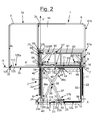
- the support frame 2 also includes an intermediate frame 7, operatively connected to the shutter 3, coupled with the base frame 6 through the translation means 4 that allow it to slide along the first direction Y to define an active position, shown in figures 2 and 3, in which the intermediate frame 7 projects from the plane II of the support structure, and a passive position, able to be seen in figure 1, in which it reenters into the space.
- the support frame 2 comprises a shaped frame 8, coupled on the outside through joining means, wholly indicated with 9 and able to be seen more clearly in figure 13, with the intermediate frame 7 with respect to which it is arranged on the same vertical plane.
- the base frame 6, the intermediate frame 7 and the shutter 3 lie on three vertical planes that are distinct and parallel to one another.
- Figures 4 and 5 also highlight that the base frame 6 is formed from two main rods 10, 11 spaced apart and defining the first direction Y, connected at the bottom by a cross-member 12, which defines a longitudinal axis X orthogonal to the first direction Y and which supports the moving means 5.
- the main rods 10, 11 are connected by a U-shaped reinforcing framework 13 provided with arms 13a, 13b fixed to the main rods 10, 11 respectively.
- the sliding door 1 In the passive condition of the intermediate frame 7, coinciding with the maximum opening of the admission, the sliding door 1 remains visible on the outside, projecting from the plane ⁇ , for just the reinforcing framework 13 of the base frame 6, which can be advantageously hidden by a furnishing component such as a sofa, a storage wall or similar.
- Figures 6 and 6b illustrate that the intermediate frame 7 is in the case under examination formed from two horizontal elements 71, 73 that are the same as one another and two vertical elements 72, 74 that are the same as one another that define a rectangular profile for the intermediate frame 7.
- the shaped frame 8 the shape of which is shown in figure 7, is advantageously equipped with a sheet of vitreous material 14, for example crystal, built into a perimetric recess 15 formed on the inner wall 8b of the top part 81b of the shaped frame 8.
- top part 81b of the shaped frame 8 projects from the intermediate frame 7 according to the first direction Y.
- the joining means 9 include a shaped profile 16, stably connected both to the intermediate frame 7 and to the shaped frame 8.
- the shaped profile 16 is arranged between the outer wall 7a of the intermediate frame 7 and the inner wall 8a of the bottom part 81a of the shaped frame 8.
- the shaped profile 16 is arranged at the ends 72a, 74a of the vertical elements 72, 74 of the intermediate frame 7, as well as at two rectilinear wings 17, 18 present in the bottom part 81a of the shaped frame 8.
- the translation means 4 preferably comprise two pairs of first sliding blocks 19, 20, each fixed to one of the vertical elements 72, 74 of the intermediate frame 7, as shown in figures 6, 6a and 6b, and two first rails 21, 22, able to be seen more clearly in figure 4, each of which matches with a pair of first sliding blocks 19, 20.
- the first rails 21, 22 are coupled with the respective front wall 10a, 11a of the corresponding main rods 10, 11, engaging its entire length.
- the number of sliding blocks and of rails per main rod can be different, just as they can be associated with just one of the rods.
- Figures 1, 2 and 3 show that preferably the moving means 5 first introduced include:
- the first guide means 25 comprise a second sliding block 27, clearly visible in figure 8b, integral with a bent plate 28, shaped like an L and near to a shaped support 29, also shown in figures 8 and 8a, joined through fixed connection means, wholly indicated with 30, to the second end 23b of the linear actuator 23.
- the first guide means 25 also comprise a second rail 31, matching with the second sliding block 27, coupled with the front surface 12a of the cross-member 12 and engaging it for more than half of its length.
- the fixed connection means 30 include a first pin 32 inserted in through holes arranged coaxially, formed in the shaped support 29, in the second end of the linear actuator 23 and in a bushing 35, arranged between the second end 23b of the linear actuator 23 and the bent plate 27.
- the transmission linkage 26 comprises two longitudinal arms 36, 37, connected together close to the intermediate area through an articulation pin 38 to form the device known in the field of mechanical construction as articulated quadrilateral.
- first longitudinal arm 36 has an end 36a pivoted through a second pin 39 to a pair of small plates 40 opposite to each other, fixed to the extremity 12b of the cross-member from which they project, and the opposite end 36b coupled with the intermediate frame 7 through second guide means, wholly indicated with 41.
- the second longitudinal arm 37 has an extremity 37a connected to the main rod 10 through third guide means, wholly indicated with 42, and the opposite extremity 37b connected to the cross-member 12 through fourth guide means, wholly indicated with 43.
- the second guide means 41 include a third sliding block 44, integral outside with the base 45a of a first plate 45, according to what has been shown in figures 9 and 9a.
- the end 36b of the first arm 36 is connected to the first plate 45 by means of a third pin 46, inserted in coaxial through holes 47, made in the first plate 45, and in a through hole, not visible, formed at the end 36b itself.
- the second guide means 41 also comprise a third rail 48, matching with the third sliding block 44, coupled with the side surface 71a of the horizontal element 71 of the intermediate frame 7.
- the third rail 48 engages the horizontal element 71 for more than half of its length.
- the third guide means 42 comprise a fourth sliding block 49, as highlighted in figures 10 and 10a, integral outside with the base 50a of a second plate 50 to which the extremity 37a of the second arm 37 is connected through a fourth pin 51.
- the pin 50 is inserted in a pair of coaxial through holes 51, formed in the second plate 50, as well as in a through hole, not represented, present at the extremity 37a of the second arm 37.
- the third guide means 42 also comprise a fourth rail 52, matching with the fourth sliding block 49, coupled with the inner wall 10b, 11b of both of the main rods 10, 11 of the base frame 6.
- the fourth guide means 43 comprise a fifth sliding block 53, integral outside with the base 54a of a third plate 54, as illustrated by figure 8b, to which the extremity 37b of the second arm 37 is connected through a fifth pin 55.
- the fourth guide means 43 comprise a fifth rail 56, matching with the fifth sliding block 53, coupled with the inner surface 12c of the cross-member 12 of the base frame 6.
- first guide means 25 and the fourth guide means 43 are constructively integral with each other and with the cross-member 12 and, since the first guide means 25 are connected to the moving means 5, are, therefore, also connected from an operative point of view, as shall be made clearer later on.
- FIGS 8b, 9a and 10a show that, preferably but not necessarily, each of the plates 54, 45 and 50 has a substantially U-shaped profile in cross section.
- the sliding door 1 comprises sliding means, wholly indicated with 57, associated with the intermediate frame 7, which allow the translation of the shutter 3 along a second direction X' orthogonal to the first direction Y.
- the shutter 3 thus defines a first operative position, not able to be seen in the drawings, in which it is arranged projecting from the base frame 6 opening the admission, and a second operative position, according to figures 2 and 3, in which it projects at the side from the intermediate frame 7 closing the admission.
- the sliding means 57 comprise a connection frame 58, shown in figures 11 and 11a, provided on the side wall 58a with a series of projecting pulleys 59, and a pair of laminar profiles 60, 61 on each of which the pulleys 59 are arranged so that they can slide.
- Each of the laminar profiles 60, 61 is coupled with one of the horizontal elements 71, 73 of the intermediate frame 7, as shown in figures 6, 6a and 6b.
- connection frame 58 is made up of four tubular bodies 62a, 62b two by two counterposed and interconnected one to the other to form a square profile.
- connection frame 58 is connected to the shutter 3 through fastening means, wholly numbered with 63, which foresee:
- Figure 12a shows that the joining means 66 include, as a non-exclusive example, a hollow body 78 made from polymeric material and having the same profile in cross section as the sliding blocks 19, 20, 27, 44, 49 and 53 mentioned earlier.
- the linear profile 65 in a side view has a substantially U-shaped profile, the same as that of the sliding blocks 45, 50 and 54.
- the sliding door 1 comprises safety means, clearly visible in figure 13 where they are wholly indicated with 79, associated with the intermediate frame 7, intended to counteract the accidental movement of the shutter 3 along a generic horizontal direction, especially during the translation along the first direction Y.
- the safety means 79 comprise a support plate 80, projecting from the side surface 71a of the horizontal element 71 of the intermediate frame 7 and fixed to it close to one of the vertices of its rectangular profile.
- the safety means 79 therefore comprise a shaped block 82, coupled cantilevered with the support plate 80 through attachment means, globally indicated with 83, and having a transversal notch 84 close to the free end 82a.
- the safety means 79 include a counter-shaped insert 85, projecting from the outer wall 621a of the tubular body 62a of the connection frame 58, as illustrated in figure 11.
- the counter-shaped insert 85 is provided with a tooth 86 that, in the first operative position of the shutter 3, engages in the transversal notch 84, whereas in the second operative position of the shutter 3 it disengages from it.
- the safety means 79 comprise elastic means, wholly numbered with 87 and consisting for example of a spring, associated on the outside with a pin 88 that, as shown in figure 14, is supported by a laminar body 89 projecting orthogonally from the outer surface 80a of the support plate 80.
- the elastic means 87 are arranged below the free end 82a of the shaped block 82 with which they cooperate to absorb the strain transmitted to it by the counter-shaped insert 85 during the opening and closing of the admission.
- the usefulness of the safety means 79 is therefore clear since they keep the shutter 3 stable in the position for coupling with the intermediate frame 7 during the movement along the first direction Y, during the course of which unadvised and accidental movements orthogonal to this direction must be prevented or limited as much as possible.
- the safety means 79 keep the shutter 3 in a stable position without bringing it back totally inside the space of the support structure.
- the safety means 79 are able to greatly limit accidental and uncontrolled sliding along the second direction X', and the consequent closing of the admission, due to strains like, for example, the rocking undergone by a boat in the port or at sea.
- the sliding door 1 comprises, generally but not necessarily, locking means, wholly indicated with 90 and visible as well as in figures 1, 2 and 3 also in the enlargements of figures 13 and 15.
- the locking means 90 are supported by a composite structure 91 integral with the intermediate frame 7 and coupled through linear sliding guides, wholly indicated with 92, with both of the main rods 10, 11 of the base frame 6.
- the linear guides 92 also in this case comprise a sixth sliding block 93, fixed to each of the side edges of the composite structure 91, and the fourth rail 52, matching, as well as with the fourth sliding block 49, also with the sixth sliding block 93.
- the locking means 90 include a pair of linear cylinders 94, electrically connected to the logic unit and connected through fitting brackets 95 to the composite structure 91.
- Each of the linear cylinders 94 is provided with a stem 96 that defines a work position in which, after the intermediate frame 7 has reached the active position, it is inserted in a side hole, not highlighted, formed on the corresponding inner wall 10b, 11b of the respective main rods 10, 11 on top of the fourth rail 52.
- the stem 96 also defines a rest position in which it is removed from the side hole to enable the sliding along the first direction Y of the intermediate frame 7 from the active position, for example when the sliding door 1 is arranged practically totally in the space of the support structure.
- the sliding door 1 comprises detection means, not represented and of the per sé known type, for example contact sensors, electrically connected to the logic unit and arranged on the base frame 6, which indicate when the shutter 3 is in the first operative position and the stem 96 of the linear cylinders 94 is in the work position.
- detection means not represented and of the per sé known type, for example contact sensors, electrically connected to the logic unit and arranged on the base frame 6, which indicate when the shutter 3 is in the first operative position and the stem 96 of the linear cylinders 94 is in the work position.
- the sliding door 1 advantageously comprises a support wheel 97, made from polyamide and height-adjustable, fixed to a ring 98 projecting from the side surface 71a of the horizontal element 71 of the intermediate frame 7.
- the support wheel 97 supports the free end 3d of the shutter 3 that would otherwise tend to bend dangerously downwards.
- the sliding door 1 also comprises first means for adjusting the position of the shutter 3 with respect to the horizontal plane ⁇ of the support structure, arranged at the side edge 3c of the shutter 3.
- the first adjustment means consist of a threaded rod 100, shown in figure 16, arranged parallel to the linear profile 65, on one side provided with a connection plate 101, fixed to the bottom surface 3b of the shutter 3, and on the opposite side inserted in a through hole 102 made in a shaped connection 103 fixed to the tubular body 62a of the connection frame 58.
- Figures 17, 17a illustrate that the shaped connection 103 has a profile respectively shaped like a P in front view and like a U in side view.
- the sliding door 1 also includes second adjustment means, wholly numbered with 104, applied to the base profile 105 of the shutter 3, suitable for arranging it parallel to the horizontal plane II of the support structure.
- Figures 18, 18a and 18b show that, in a preferred but not limiting manner, the second adjustment means 104 include a threaded rod 106 and a bushing 107 coupled on the outside with such a rod 106.
- the bushing 104 has a series of radial holes 108 suitable for receiving a tool, for example a key or any sort of nib, for rotation about the axis Y'.
- the second adjustment means 104 also comprise a contact pulley 109 associated with the bottom part 106a of the threaded rod 106 and projecting by a variable amount from the bottom surface 3b of the shutter 3 to be arranged near to the plane II of the support structure.
- the threaded rod 106 is arranged passing through a shaped bracket 110 fixed to the top edge 105a of the base profile 105 of the shutter 3 and in which a recess 111 is defined that receives a plate 112, U-shaped in cross section and supported by the threaded rod 106.
- the contact pulley 109 is made integral with the plate 112 through connection means, wholly indicated with 113, which specifically include a pin 114 inserted through the interposition of a bearing 115 in an axial through hole, not visible, formed in the contact pulley 109, and in a slotted through hole 116 made in a support shoulder 117 connected to the shaped bracket 110.
- the object of the present invention is also the method for moving the sliding door 1 for opening/closing admissions described here.
- the sliding of the shutter 3 takes place along the first direction Y according to which the distance between the top surface 3a and the bottom surface 3b of the shutter 3 can be calculated.
- the first direction Y is vertical and incident a horizontal plane II defined by the support structure.
- the sliding of the shutter 3 takes place through a translation along the first direction Y of the mobile intermediate frame 7 that belongs to the support frame 2 and supports the shutter 3.
- the translation of the intermediate frame 7 is automatic, thanks to the actuation of the moving means 4 by the command means.
- the translation of the intermediate frame 7 takes place according to opposite directions that arrange it alternately in an active position and in a passive position.
- the intermediate frame 7 projects from the plane II of the support structure and arranges the shutter 3 in a first operative condition, beside the admission.
- the intermediate frame 7 reenters in a space of the support structure arranged below the horizontal plane II of it and adjacent to the admission.
- the translation along the first direction Y consists of an initial raising and a subsequent lowering of the intermediate frame 7 respectively from the passive position towards the active position and vice-versa.
- the stem 118 of the linear actuator 23 reenters into the chamber 119 making the second sliding block 27 and the fifth sliding block 53 slide, respectively, along the second rail 31 and along the fifth rail 56 of the cross-member 12, the third sliding block 44 along the third rail 48, as well as the sliding blocks 49 and 93 along the fourth rail 52.
- the raising and lowering cycles of the intermediate frame 7 are repeated many times, according to the requirements of use of the sliding door 1.
- the method of the invention also includes a moving operation of the shutter 3 along a second direction X' substantially orthogonal to the first direction Y, carried out after the translation of the intermediate frame 7 according to a first direction along the first direction Y.
- the moving operation of the shutter 3 in this case takes place manually, thanks to the intervention of the operator, but it is clear that it is possible to foresee other variant applications in which such an operation is carried out automatically.
- the moving operation of the shutter 3 along the second direction X' takes place according to opposite directions to arrange it alternately between the first operative condition, in which it keeps the admission open, and the second operative condition in which it closes the admission itself.
- the method according to the invention comprises a locking operation of the intermediate frame 7 in the active position, carried out after the translation according to the first direction along the first direction Y.
- the locking operation is carried out before arranging the shutter 3 in the second operative condition.
- the locking operation is piloted by the logic unit and consists of arranging the stem 96 of the linear cylinders 94 inside the side holes of the main rods 10, 11.
- the locking of the intermediate frame 7 also takes place keeping the counter-shaped insert 85 matching with the shaped block 82 thanks to the coupling of the tooth 86 in the transversal notch 84.
- the operator pulls the shutter 3, freeing the tooth 86 from the transversal notch 84, and makes it slide along the second direction X' in one direction.
- the operator pushes the shutter 3 in the opposite direction along the horizontal direction X', preferably but not exclusively until the tooth 86 is coupled again in the transversal notch 84 to avoid sudden and accidental movements of the shutter 3 along the second direction X', due for example to stresses, rocking or something else of the support structure.
- the method of the invention therefore comprises an unlocking operation of the intermediate frame 7 from the active position, carried out before the translation of the intermediate frame 7 in a second direction along the first direction Y, in order to allow it to be arranged in the passive position.
- the method comprises an operation to detect the position of the shutter 3 and to lock the intermediate frame 7, carried out before the unlocking operation of the intermediate frame.
- the detection operation takes place when the shutter 3 is in the first operative condition and indicates to the logic unit the possibility or not of moving the intermediate frame 7 along the first direction Y, in particular of lowering it to put it back in the space of the support structure below the plane II.
- the locking, detection and unlocking operations take place automatically.
- the sliding door of the invention thus has a smaller bulk than equivalent known doors, especially when it leaves the admission open and reenters in the space made in the support structure.
- the sliding door allows aeration of the top room compared to the prior art, at the same time ensuring a wider view of the outside.
- the door of the invention can be moved extremely practically and easily.
- the sliding blocks 19, 20, 27, 44, 49, 53 and 93 introduced during the course of the description are made from polymeric material.
- the sliding door of the invention can be installed in any support structure where a space or gap is foreseen or can in any case been formed in an area above or below the room that the door itself must serve.
- the sliding door of the invention lends itself to installation in boats, for example in the aft area.
Landscapes
- Engineering & Computer Science (AREA)
- Civil Engineering (AREA)
- Structural Engineering (AREA)
- Chemical & Material Sciences (AREA)
- Combustion & Propulsion (AREA)
- Mechanical Engineering (AREA)
- Ocean & Marine Engineering (AREA)
- Wing Frames And Configurations (AREA)
- Power-Operated Mechanisms For Wings (AREA)
Applications Claiming Priority (1)
| Application Number | Priority Date | Filing Date | Title |
|---|---|---|---|
| ITVI20060282 ITVI20060282A1 (it) | 2006-09-22 | 2006-09-22 | Porta scorrevole per l'apertura/chiusura di accessi e metodo di movimentazione di tale porta |
Publications (2)
| Publication Number | Publication Date |
|---|---|
| EP1905933A2 true EP1905933A2 (de) | 2008-04-02 |
| EP1905933A3 EP1905933A3 (de) | 2011-08-24 |
Family
ID=38845145
Family Applications (1)
| Application Number | Title | Priority Date | Filing Date |
|---|---|---|---|
| EP07116534A Withdrawn EP1905933A3 (de) | 2006-09-22 | 2007-09-17 | Schiebetür zum Öffnen und Schließen von Zugängen und Verfahren zum Bewegen einer solchen Tür |
Country Status (2)
| Country | Link |
|---|---|
| EP (1) | EP1905933A3 (de) |
| IT (1) | ITVI20060282A1 (de) |
Cited By (3)
| Publication number | Priority date | Publication date | Assignee | Title |
|---|---|---|---|---|
| CN103982113A (zh) * | 2014-05-30 | 2014-08-13 | 江苏友奥电器有限公司 | 带滑盖门的出风口机构 |
| ITUA20162675A1 (it) * | 2016-04-18 | 2017-10-18 | Helium Tech S R L | Camera a vuoto e impianto comprendente detta camera a vuoto |
| CN113051664A (zh) * | 2021-03-25 | 2021-06-29 | 重庆长安汽车股份有限公司 | 一种中滑门与车身的匹配间隙优化方法 |
Family Cites Families (2)
| Publication number | Priority date | Publication date | Assignee | Title |
|---|---|---|---|---|
| DE1534826A1 (de) * | 1965-12-07 | 1969-10-09 | Erich Wildner | Zwischen plattenfoermigen vorfabrizierten Wandelementen angeordnetes Fenster |
| AT8630U1 (de) * | 2005-03-10 | 2006-10-15 | Herbert Neubacher | In einen unterflurschacht versenkbares wandelement |
-
2006
- 2006-09-22 IT ITVI20060282 patent/ITVI20060282A1/it unknown
-
2007
- 2007-09-17 EP EP07116534A patent/EP1905933A3/de not_active Withdrawn
Cited By (6)
| Publication number | Priority date | Publication date | Assignee | Title |
|---|---|---|---|---|
| CN103982113A (zh) * | 2014-05-30 | 2014-08-13 | 江苏友奥电器有限公司 | 带滑盖门的出风口机构 |
| CN103982113B (zh) * | 2014-05-30 | 2015-12-02 | 江苏友奥电器有限公司 | 带滑盖门的出风口机构 |
| ITUA20162675A1 (it) * | 2016-04-18 | 2017-10-18 | Helium Tech S R L | Camera a vuoto e impianto comprendente detta camera a vuoto |
| WO2017182898A1 (en) * | 2016-04-18 | 2017-10-26 | Helium Technology Srl | Vacuum chamber and plant comprising said vacuum chamber |
| CN113051664A (zh) * | 2021-03-25 | 2021-06-29 | 重庆长安汽车股份有限公司 | 一种中滑门与车身的匹配间隙优化方法 |
| CN113051664B (zh) * | 2021-03-25 | 2022-07-08 | 重庆长安汽车股份有限公司 | 一种中滑门与车身的匹配间隙优化方法 |
Also Published As
| Publication number | Publication date |
|---|---|
| EP1905933A3 (de) | 2011-08-24 |
| ITVI20060282A1 (it) | 2008-03-23 |
Similar Documents
| Publication | Publication Date | Title |
|---|---|---|
| US8117670B2 (en) | Variable volume container unit hoisting device for lowering and raising a telescopical expansion element | |
| KR101618300B1 (ko) | 다용도 창호 | |
| RU2431730C2 (ru) | Система фурнитуры для отставляемых сдвижных створок | |
| US4802247A (en) | Door bath tube for the handicapped | |
| EP1905933A2 (de) | Schiebetür zum Öffnen und Schließen von Zugängen und Verfahren zum Bewegen einer solchen Tür | |
| US4590707A (en) | Releasable panel assembly for window frame or the like | |
| CN109477356A (zh) | 用于窗或门的作为滑动扇的可活动的扇或可活动的提升滑动扇的底梁系统 | |
| US20030106649A1 (en) | Awning, especially articulated arm awning | |
| EP3568548B9 (de) | Versteckter heberahmen mit schliessmechanismus | |
| EP2305553B1 (de) | Seitliche Servicetür für Boote | |
| US9586463B2 (en) | Top for an openable vehicle roof | |
| US20080303293A1 (en) | Locking Device | |
| EP0885834B1 (de) | Leichter Wagenheber | |
| ITPN20130052A1 (it) | Serramento a tenuta avente almeno un¿anta scorrevole | |
| US6401629B1 (en) | Door for railroad car | |
| FI84645C (fi) | Svaengbar glasbelaeggning. | |
| EP3682079A1 (de) | Schwingfenster | |
| EP1911918B1 (de) | Zugangstür, insbesondere für Boote | |
| US20020092240A1 (en) | Door for a railway vehicle | |
| IT202100019229A1 (it) | Sistema di incernieramento a scomparsa per porte o finestre. | |
| KR101372577B1 (ko) | 리프트 창문용 호차 어셈블리 | |
| GB2095735A (en) | Shower enclosure doors | |
| EP3578738B1 (de) | Betriebsmechanismus für eine hebe-schiebetür und eine mit einem solchen mechanismus ausgestattete hebe-schiebetür | |
| EP1960623A1 (de) | Verriegelungsvorrichtung | |
| IT201800003481A1 (it) | Serramento |
Legal Events
| Date | Code | Title | Description |
|---|---|---|---|
| PUAI | Public reference made under article 153(3) epc to a published international application that has entered the european phase |
Free format text: ORIGINAL CODE: 0009012 |
|
| AK | Designated contracting states |
Kind code of ref document: A2 Designated state(s): AT BE BG CH CY CZ DE DK EE ES FI FR GB GR HU IE IS IT LI LT LU LV MC MT NL PL PT RO SE SI SK TR |
|
| AX | Request for extension of the european patent |
Extension state: AL BA HR MK YU |
|
| PUAL | Search report despatched |
Free format text: ORIGINAL CODE: 0009013 |
|
| AK | Designated contracting states |
Kind code of ref document: A3 Designated state(s): AT BE BG CH CY CZ DE DK EE ES FI FR GB GR HU IE IS IT LI LT LU LV MC MT NL PL PT RO SE SI SK TR |
|
| AX | Request for extension of the european patent |
Extension state: AL BA HR MK RS |
|
| RIC1 | Information provided on ipc code assigned before grant |
Ipc: E06B 3/44 20060101AFI20110721BHEP |
|
| AKY | No designation fees paid | ||
| REG | Reference to a national code |
Ref country code: DE Ref legal event code: R108 Effective date: 20120502 |
|
| STAA | Information on the status of an ep patent application or granted ep patent |
Free format text: STATUS: THE APPLICATION IS DEEMED TO BE WITHDRAWN |
|
| 18D | Application deemed to be withdrawn |
Effective date: 20120225 |