EP1905902B1 - Working machine including a rotation control device - Google Patents
Working machine including a rotation control device Download PDFInfo
- Publication number
- EP1905902B1 EP1905902B1 EP07117234.0A EP07117234A EP1905902B1 EP 1905902 B1 EP1905902 B1 EP 1905902B1 EP 07117234 A EP07117234 A EP 07117234A EP 1905902 B1 EP1905902 B1 EP 1905902B1
- Authority
- EP
- European Patent Office
- Prior art keywords
- rotation
- operation amount
- hydraulic actuator
- torque
- hydraulic
- Prior art date
- Legal status (The legal status is an assumption and is not a legal conclusion. Google has not performed a legal analysis and makes no representation as to the accuracy of the status listed.)
- Active
Links
- 230000001133 acceleration Effects 0.000 claims description 36
- 238000000034 method Methods 0.000 description 8
- 238000010586 diagram Methods 0.000 description 6
- 239000000470 constituent Substances 0.000 description 3
- 230000003247 decreasing effect Effects 0.000 description 1
- 230000001419 dependent effect Effects 0.000 description 1
- 230000000694 effects Effects 0.000 description 1
- 238000006467 substitution reaction Methods 0.000 description 1
Images


Classifications
-
- E—FIXED CONSTRUCTIONS
- E02—HYDRAULIC ENGINEERING; FOUNDATIONS; SOIL SHIFTING
- E02F—DREDGING; SOIL-SHIFTING
- E02F9/00—Component parts of dredgers or soil-shifting machines, not restricted to one of the kinds covered by groups E02F3/00 - E02F7/00
- E02F9/08—Superstructures; Supports for superstructures
- E02F9/10—Supports for movable superstructures mounted on travelling or walking gears or on other superstructures
- E02F9/12—Slewing or traversing gears
- E02F9/121—Turntables, i.e. structure rotatable about 360°
- E02F9/123—Drives or control devices specially adapted therefor
-
- E—FIXED CONSTRUCTIONS
- E02—HYDRAULIC ENGINEERING; FOUNDATIONS; SOIL SHIFTING
- E02F—DREDGING; SOIL-SHIFTING
- E02F9/00—Component parts of dredgers or soil-shifting machines, not restricted to one of the kinds covered by groups E02F3/00 - E02F7/00
- E02F9/20—Drives; Control devices
- E02F9/2058—Electric or electro-mechanical or mechanical control devices of vehicle sub-units
- E02F9/2062—Control of propulsion units
- E02F9/2075—Control of propulsion units of the hybrid type
Definitions
- the present invention relates to a hydraulic/electric combination type rotation control device for a working machine of simultaneously using a hydraulic action by a hydraulic actuator and a rotation action by an electric motor.
- the excavator is, as shown in Figs. 7 and 8 , is configured such that an upper rotating body 2 is rotatably mounted on a crawler type lower traveling body 1 around a vertical axis O.
- On the upper rotating body 2 is installed an excavating attachment A provided with a boom 3, an arm 4, a bucket 5, a boom cylinder 6, an arm cylinder 7, and a bucket cylinder 8.
- Patent Document 1 a total hydraulic drive method in which all the actions are performed by a hydraulic actuator driven by a hydraulic pump in the excavator, as proposed in WO2006/004080A1 (hereinafter, referred to as Patent Document 1), there is a hydraulic/electric combination method in which a rotation action is performed by an electric motor (rotation motor) and other actions are performed by the hydraulic actuator driven by the hydraulic pump as in the past.
- an excavator using the total hydraulic drive method is called as a total hydraulic excavator
- an excavator using the combination method is called as a combination excavator.
- Patent Document 1 in order to deal with the problem of uncomfortableness due to the fact that the rotation speed is not changed relative to a change of a rotation rate of an engine, the rotation speed is changed in accordance with the rotation rate of the engine so as to perform control for imitating the movement of the total hydraulic excavator.
- WO 2006/054582 A discloses that a rotation control device of an electrically rotated shovel performs control of a rotating body by a small first torque command value T1 when the rotating body is rotated at constant speed. Therefore, variation in inertia moment of the rotating body varies by telescoping of a boom or an arm affects the rotation speed of the rotating body, enabling rotation operation to be carried out with a sense similar to that in hydraulic drive.
- rotation control is performed by a large second torque command value T2. Consequently, acceleration/deceleration is performed quickly and good lively operational feeling can be attained without sacrifice of workability.
- the rotation motor is torque-controlled in the direction of slowing down the acceleration of the rotation in accordance with the increase in the hydraulic actuator operation amount at the time of the combined operation for simultaneously performing the rotation action and the hydraulic operation (particularly boom raising action). Therefore, it is possible to achieve a move or sense which is extremely close to movement of the total hydraulic excavator in which while the acceleration is slowed down, the speed is reduced. Consequently, there is no uncomfortableness in comparison to the total hydraulic excavator, and it is possible to improve the operability at this point.
- the control means torque-controls the rotation motor in the direction of reducing rotation torque in accordance with the increase in the hydraulic actuator operation amount at the time of the combined operation.
- the "direction of reducing rotation torque" corresponds to the direction of slowing down the acceleration of the rotation in accordance with the increase in the hydraulic actuator operation amount in the above basic configuration.
- a speed target value in accordance with the rotation operation amount is determined.
- a process for limiting the torque command value is performed.
- the "direction of reducing rotation acceleration” corresponds to the direction of slowing down the acceleration of the rotation in accordance with the increase in the hydraulic actuator operation amount in the above basic configuration.
- control means torque-controls the rotation motor in the direction of reducing the rotation acceleration in accordance with the hydraulic actuator operation amount at the time of the combined operation.
- a speed target value in accordance with the rotation operation amount is determined.
- a process for limiting the acceleration is performed.
- a final acceleration pattern is the same as described later, and it is possible to obtain a result of the speed reduction with the slow down of the acceleration.
- Fig. 1 shows an entire configuration of a rotation control device according to the first embodiment.
- a hydraulic circuit 15 is connected to the hydraulic pump 13, and a boom cylinder 6 shown in Fig. 7 and other hydraulic actuators (given the reference numeral 16 in total) are driven by pressure oil from the hydraulic pump 13.
- Power from the generator motor 14 is sent to a rotation motor 19 through both a generator motor inverter 17 and a rotation motor inverter 18. Torque of the rotation motor 19 is transmitted to an upper rotating body 2 through a reduction gear 20, and the upper rotating body 2 is rotated around a vertical axis O shown in Figs. 7 and 8 .
- a battery 21 is provided between both the inverters 17 and 18.
- the battery 21 is combined with the generator motor 14 and used as a power source for the rotation motor 19.
- the reference numeral 22 denotes an encoder serving as rotation speed detecting means for detecting rotation speed of the rotation motor 19.
- the rotation speed detected by the encoder 22 is inputted to a controller 23 serving as control means.
- the reference numeral 24 denotes a rotation lever serving as rotation operation means (one rotation lever is shown as used for rotation of both left and right), and the reference numeral 25 denotes a boom raising lever serving as boom raising operation means. Operation amounts of both the levers 24 and 25 (a rotation operation amount and a boom raising operation amount) are detected by operation amount detecting means 28 serving both as rotation operation amount detecting means and boom raising operation amount detecting means through signal converters 26 and 27 such as a potentiometer, and inputted to the controller 23.
- a remote controller valve may be used as the boom raising operation means so that an operation amount thereof is converted into an electric signal by a pilot pressure sensor and sent to the operation amount detecting means 28.
- the controller 23 is, as basic constituent elements, provided with rotation speed target value calculating means 29 for calculating a target value of the rotation speed from the rotation operation amount, rotation acceleration and deceleration control means 30 for outputting a command value of the rotation speed on the basis of the rotation speed target value, rotation speed detected value calculating means 31 for determining the rotation speed from a rotation speed signal sent from the encoder 22, rotation speed control means 32 for performing rotation speed feedback control (PI control), and motor torque control means 33.
- rotation speed target value calculating means 29 for calculating a target value of the rotation speed from the rotation operation amount
- rotation acceleration and deceleration control means 30 for outputting a command value of the rotation speed on the basis of the rotation speed target value
- rotation speed detected value calculating means 31 for determining the rotation speed from a rotation speed signal sent from the encoder 22
- rotation speed control means 32 for performing rotation speed feedback control (PI control), and motor torque control means 33.
- the rotation motor 19 is rotated at speed in accordance with the rotation operation amount so that the upper rotating body 2 shown in Figs. 7 and 8 is rotated.
- rotation torque limitation value setting means 34 and rotation torque limiting means 35 are provided as constituent elements of making the rotation movement closer to hydraulic rotation at the time of the combined operation of rotating and boom raising.
- a limitation value of the rotation torque is determined from a property of boom raising operation amount/torque limitation value which is preset, and sent to the rotation torque limiting means 35.
- the rotation torque command value from the rotation speed control means 32 is limited on the basis of the rotation torque limitation value, and the limited value serving as a final rotation torque command value is sent to the motor torque control means 33.
- rotation acceleration limitation value setting means 36 is provided instead of the rotation torque limitation value setting means 34 of the first embodiment.
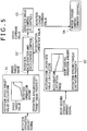
- the rotation acceleration limitation value setting means 36 is adapted to determine an acceleration limitation value from a property of boom raising operation amount/torque limitation value which is preset on the basis of the boom raising operation amount, and send the acceleration value to the rotation acceleration and deceleration control means 30, as Control Step S5' in Fig. 5 instead of Control Step S5 in Fig. 2 .
- the rotation speed command value is determined by adding acceleration limitation to the rotation speed target value from the rotation speed target value calculating means 29, and sent to the rotation speed control means 32.
Landscapes
- Engineering & Computer Science (AREA)
- Mining & Mineral Resources (AREA)
- Civil Engineering (AREA)
- General Engineering & Computer Science (AREA)
- Structural Engineering (AREA)
- Operation Control Of Excavators (AREA)
- Earth Drilling (AREA)
Description
- The present invention relates to a hydraulic/electric combination type rotation control device for a working machine of simultaneously using a hydraulic action by a hydraulic actuator and a rotation action by an electric motor.
- THE RELATED ART will be described taking an excavator as an example.
- The excavator is, as shown in
Figs. 7 and 8 , is configured such that an upper rotatingbody 2 is rotatably mounted on a crawler type lower travelingbody 1 around a vertical axis O. On the upper rotatingbody 2, is installed an excavating attachment A provided with aboom 3, anarm 4, abucket 5, aboom cylinder 6, anarm cylinder 7, and abucket cylinder 8. - Instead of a total hydraulic drive method in which all the actions are performed by a hydraulic actuator driven by a hydraulic pump in the excavator, as proposed in
WO2006/004080A1 (hereinafter, referred to as Patent Document 1), there is a hydraulic/electric combination method in which a rotation action is performed by an electric motor (rotation motor) and other actions are performed by the hydraulic actuator driven by the hydraulic pump as in the past. Hereinafter, as necessary, an excavator using the total hydraulic drive method is called as a total hydraulic excavator, and an excavator using the combination method is called as a combination excavator. - In the combination excavator, since the rotation action is independently performed by the electric motor and not influenced by a hydraulic action, movement which is different from the total hydraulic excavator is generated at the time of a combined operation for simultaneously performing the rotation action and the hydraulic operation.
- As a representative example, at the time of a combined operation of rotating and boom raising for raising the
boom 3 while rotating, in the total hydraulic excavator, since a oil supply amount to a rotation motor (hydraulic motor) is decreased by raising the boom, rotation speed is reduced and a degree of speed reduction is changed in accordance with a boom raising operation amount. - Therefore, there is a problem that an operator who is accustomed to such movement of the total hydraulic excavator feels uncomfortable with the movement of the combination excavator in which the rotation speed is not changed at the time of the combined operation, and operability is bad at this point.
- It should be noted that in
Patent Document 1, in order to deal with the problem of uncomfortableness due to the fact that the rotation speed is not changed relative to a change of a rotation rate of an engine, the rotation speed is changed in accordance with the rotation rate of the engine so as to perform control for imitating the movement of the total hydraulic excavator. - Therefore, by applying the technique, it is possible to control the rotation motor so that the rotation speed is reduced in accordance with for example the boom raising operation amount at the time of the combined operation of rotating and boom raising.
- However, as a rotation property of the total hydraulic excavator at the time of the combined operation, pressure is lowered at the same time as a decrease in an oil amount supplied from the pump to the rotation motor so that acceleration is slowed down and the speed is reduced. Therefore, even if feedback speed control for eliminating deviation between target speed and actual speed is performed, the speed would only reach a target value at the end but it is not possible to obtain a move or sense of the "slow down of acceleration".
- Particularly, at the time of the combined operation of rotating and boom raising, a change in the oil supply amount to the boom cylinder is large and hence the slow down of acceleration is radical in the total hydraulic excavator. Therefore, the hydraulic rotation property is not sufficiently achieved by simple speed control and the uncomfortableness remains in the operation.
- Document
WO 2006/054582 A discloses that a rotation control device of an electrically rotated shovel performs control of a rotating body by a small first torque command value T1 when the rotating body is rotated at constant speed. Therefore, variation in inertia moment of the rotating body varies by telescoping of a boom or an arm affects the rotation speed of the rotating body, enabling rotation operation to be carried out with a sense similar to that in hydraulic drive. On the other hand, when acceleration is made by operating a rotation lever, rotation control is performed by a large second torque command value T2. Consequently, acceleration/deceleration is performed quickly and good lively operational feeling can be attained without sacrifice of workability. - It is an object of the present invention to provide a rotation control device for working machine which is capable of making a rotation property at the time of a combined operation closer to a rotation property of a total hydraulic excavator so as to improve operability.
- In order to achieve such an object, according to the present invention, there is provided a working machine as defined in
claim 1. Preferred embodiments of the present invention are set out in the dependent claims. - According to the present invention, the rotation motor is torque-controlled in the direction of slowing down the acceleration of the rotation in accordance with the increase in the hydraulic actuator operation amount at the time of the combined operation for simultaneously performing the rotation action and the hydraulic operation (particularly boom raising action). Therefore, it is possible to achieve a move or sense which is extremely close to movement of the total hydraulic excavator in which while the acceleration is slowed down, the speed is reduced. Consequently, there is no uncomfortableness in comparison to the total hydraulic excavator, and it is possible to improve the operability at this point.
- In the present invention, it is preferable that in the above basic configuration, the control means torque-controls the rotation motor in the direction of reducing rotation torque in accordance with the increase in the hydraulic actuator operation amount at the time of the combined operation. Here, the "direction of reducing rotation torque" corresponds to the direction of slowing down the acceleration of the rotation in accordance with the increase in the hydraulic actuator operation amount in the above basic configuration.
- In this case, in the control in the direction of reducing the rotation torque, a speed target value in accordance with the rotation operation amount is determined. At a stage where a torque command is sent to the rotation motor for speed control for achieving the speed target value, a process for limiting the torque command value is performed. Here, the "direction of reducing rotation acceleration" corresponds to the direction of slowing down the acceleration of the rotation in accordance with the increase in the hydraulic actuator operation amount in the above basic configuration.
- In the present invention, it is preferable that in the above basic configuration, the control means torque-controls the rotation motor in the direction of reducing the rotation acceleration in accordance with the hydraulic actuator operation amount at the time of the combined operation.
- In this case, in the control in the direction of reducing the rotation acceleration, a speed target value in accordance with the rotation operation amount is determined. At a stage where a speed command value is determined for speed control for achieving the speed target value, a process for limiting the acceleration is performed. However, a final acceleration pattern is the same as described later, and it is possible to obtain a result of the speed reduction with the slow down of the acceleration.
-
Fig. 1 is an entire block diagram of a control device according to a first embodiment of the present invention; -
Fig. 2 is a control block diagram for explaining a control content according to the first embodiment; -
Fig. 3 is a diagram showing changing situations relative to time of rotation torque and rotation speed as a control result according to the first embodiment; -
Fig. 4 is an entire block diagram of a control device according to a second embodiment; -
Fig. 5 is a control block diagram for explaining a control content according to the second embodiment; -
Fig. 6 is a diagram showing changing situations relative to time of rotation acceleration and rotation speed as a control result according to the second embodiment; -
Fig. 7 is a schematic side view of an excavator; and -
Fig. 8 is a schematic front view of the excavator. - A description will be given to embodiments of the present invention with reference to
Figs. 1 to 6 . - In a first embodiment shown in
Figs. 1 to 3 , "control in the direction of reducing rotation torque" is performed in correspondence withclaim 2, and in a second embodiment shown inFigs. 4 to 6 , "control in the direction of reducing rotation acceleration" is performed in correspondence withclaim 3. -
Fig. 1 shows an entire configuration of a rotation control device according to the first embodiment. - Firstly, when drive system is explained, power of an
engine 11 is added to ahydraulic pump 13 and agenerator motor 14 through apower divider 12. - A
hydraulic circuit 15 is connected to thehydraulic pump 13, and aboom cylinder 6 shown inFig. 7 and other hydraulic actuators (given thereference numeral 16 in total) are driven by pressure oil from thehydraulic pump 13. - Power from the
generator motor 14 is sent to arotation motor 19 through both agenerator motor inverter 17 and arotation motor inverter 18. Torque of therotation motor 19 is transmitted to an upper rotatingbody 2 through areduction gear 20, and the upper rotatingbody 2 is rotated around a vertical axis O shown inFigs. 7 and 8 . - A
battery 21 is provided between both theinverters battery 21 is combined with thegenerator motor 14 and used as a power source for therotation motor 19. - The
reference numeral 22 denotes an encoder serving as rotation speed detecting means for detecting rotation speed of therotation motor 19. The rotation speed detected by theencoder 22 is inputted to acontroller 23 serving as control means. - The
reference numeral 24 denotes a rotation lever serving as rotation operation means (one rotation lever is shown as used for rotation of both left and right), and thereference numeral 25 denotes a boom raising lever serving as boom raising operation means. Operation amounts of both thelevers 24 and 25 (a rotation operation amount and a boom raising operation amount) are detected by operation amount detecting means 28 serving both as rotation operation amount detecting means and boom raising operation amount detecting means throughsignal converters controller 23. - It should be noted that a remote controller valve may be used as the boom raising operation means so that an operation amount thereof is converted into an electric signal by a pilot pressure sensor and sent to the operation amount detecting means 28.
- The
controller 23 is, as basic constituent elements, provided with rotation speed target value calculating means 29 for calculating a target value of the rotation speed from the rotation operation amount, rotation acceleration and deceleration control means 30 for outputting a command value of the rotation speed on the basis of the rotation speed target value, rotation speed detected value calculatingmeans 31 for determining the rotation speed from a rotation speed signal sent from theencoder 22, rotation speed control means 32 for performing rotation speed feedback control (PI control), and motor torque control means 33. - A basic speed control effect according to the basic constituent elements will be described with reference to
Fig. 2 . - (i) In the rotation speed target value calculating means 29, the target value of the rotation speed is determined from the rotation operation amount signal (Control Step S1 in
Fig. 2 ). - (ii) In the rotation acceleration and deceleration control means 30, the command value of the rotation speed for the rotation acceleration and deceleration control in accordance with the rotation speed target value is determined, and the rotation speed command value is sent to the rotation speed control means 32 (Control Step S2 in
Fig. 2 ). - (iii) In the rotation speed control means 32, the rotation torque which is necessary for achieving command speed is determined, and the rotation torque serving as a rotation torque command value is outputted to the motor torque control means 33 (Control Step S3 in
Fig. 2 ). - (iv) In the motor torque control means 33, a current value in accordance with the rotation torque command value is determined and outputted to the inverter 18 (Control Step S4 in
Fig. 2 ). - By this, the
rotation motor 19 is rotated at speed in accordance with the rotation operation amount so that the upper rotatingbody 2 shown inFigs. 7 and 8 is rotated. - Here, when applying the technique disclosed in
Patent Document 1, as the control of making the rotation movement closer to the rotation movement of the total hydraulic excavator at the time of the combined operation of rotating and boom raising, the speed command value in Control Step S2 is reduced in accordance with the boom raising operation amount, and speed feedback control is performed on the basis of the reduced speed command. - Meanwhile in the first embodiment, as constituent elements of making the rotation movement closer to hydraulic rotation at the time of the combined operation of rotating and boom raising, are provided rotation torque limitation value setting means 34 and rotation torque limiting means 35.
- In the rotation torque limitation value setting means 34, on the basis of the boom raising operation amount from the operation
amount detecting means 28, as Control Step S5 inFig. 2 , a limitation value of the rotation torque is determined from a property of boom raising operation amount/torque limitation value which is preset, and sent to the rotationtorque limiting means 35. - In the rotation torque limiting means 35, as Control Step S6, the rotation torque command value from the rotation speed control means 32 is limited on the basis of the rotation torque limitation value, and the limited value serving as a final rotation torque command value is sent to the motor torque control means 33.
- As a result, at the time of the combined operation of rotating and boom raising, the rotation torque is limited and the acceleration is slowed down as shown in
Fig. 3 . The more the boom raising operation amount is, the tighter the torque limitation (slow down of acceleration) becomes. - Therefore, it is possible to obtain the rotation property which is extremely close to the hydraulic rotation in which while the acceleration is slowed down, the speed is reduced in accordance with the boom raising operation amount.
- In the second embodiment shown in
Figs. 4 to 6 , the same parts as in the first embodiment are given the same reference numerals and repeated explanation thereof is omitted. - When different points from the first embodiments are explained, as understood from comparison between
Figs. 1 and4 , rotation acceleration limitation value setting means 36 is provided instead of the rotation torque limitation value setting means 34 of the first embodiment. - The rotation acceleration limitation value setting means 36 is adapted to determine an acceleration limitation value from a property of boom raising operation amount/torque limitation value which is preset on the basis of the boom raising operation amount, and send the acceleration value to the rotation acceleration and deceleration control means 30, as Control Step S5' in
Fig. 5 instead of Control Step S5 inFig. 2 . - In the rotation acceleration and deceleration control means 30 receiving the acceleration limitation value, as Control Step S2', the rotation speed command value is determined by adding acceleration limitation to the rotation speed target value from the rotation speed target value calculating means 29, and sent to the rotation speed control means 32.
- As a result, the rotation acceleration is slowed down in accordance with the boom raising operation amount as shown in
Fig. 6 , and it is possible to obtain the rotation property which is extremely close to the hydraulic rotation in which while the acceleration is slowed down, the rotation speed is reduced as well as the first embodiment. -
- (1) In both the above embodiments, the boom raising action is taken as a representative example for a hydraulic action in which the rotation speed is reduced at the time of combined operation. However, it is possible to apply the present invention to combination with other hydraulic actions generating similar phenomenon.
- (2) In both the above embodiments, it is shown that the present invention is applied to a so-called hybrid excavator in which the
rotation motor 19 is driven by thegenerator motor 14 and thebattery 21 and thehydraulic pump 13 is driven by theengine 11. However, it is possible to apply the present invention to an excavator in which a rotation motor and a motor for pump are driven by an external power source or a battery and a hydraulic pump is driven by the motor for pump. - (3) The present invention is not limited to the excavator but widely applied to a working machine of an electrically rotated type such as a crusher, a demolition machine and a groove excavator which are configured so as to take the excavator as a base.
- Although the invention has been described with reference to the preferred embodiments in the attached figures, it is noted that equivalents may be employed and substitutions made herein without departing from the scope of the invention as recited in the claims.
Claims (4)
- A working machine, comprising:a rotation body (2);an electric rotation motor (19) for rotating and driving said rotation body (2);a hydraulic pump (13) for driving a hydraulic actuator (6, 16) by pressure oil from the hydraulic pump (13);rotation operation means (24) for sending a rotation signal to said electric rotation motor (19);hydraulic actuator operation means (25) for sending an action signal to said hydraulic actuator (6, 16);rotation operation amount detecting means (28) for detecting a rotation operation amount which is an operation amount of said rotation operation means (24);hydraulic actuator operation amount detecting means (28) for detecting a hydraulic actuator operation amount which is an operation amount of said hydraulic actuator operation means (25); andcontrol means (23) for controlling said electric rotation motor (19) on the basis of the signals from both said rotation and hydraulic actuator operation amount detecting means (28), the control means (23) including:rotation speed target value calculating means (29) for calculating a rotation speed target value from the rotation operation amount of the rotation operation amount detecting means (28);limitation value setting means (34, 36) for setting a limitation value based on the hydraulic actuator operation amount of the hydraulic actuator operation amount detecting means (28) to limit calculation of a final rotation torque command value based on the rotation speed target value,the final rotation torque command value being adapted:(A) to control said electric rotation motor (19) at speed in accordance with the rotation operation amount when no hydraulic action by said hydraulic actuator (6, 16) is performed, and(B) to torque-control said electric rotation motor (19) in the direction of slowing down acceleration of the rotation in accordance with an increase in the hydraulic actuator operation amount at the time of a combined operation for simultaneously performing a rotation action and a hydraulic action by said hydraulic actuator (6, 16).
- The working machine according to claim 1, wherein
said control means (23) torque-controls said electric rotation motor (19) in the direction of reducing rotation torque in accordance with the increase in the hydraulic actuator operation amount at the time of the combined operation. - The working machine according to claim 1, wherein
said control means (23) torque-controls said electric rotation motor (19) in the direction of reducing the rotation acceleration in accordance with the hydraulic actuator operation amount at the time of the combined operation. - The working machine according to claim 1, whereinsaid hydraulic actuator (6, 16) includes a boom cylinder (6) for raising and lowering a boom,said hydraulic actuator operation means (25) includes boom raising operation means (25) for sending a command for raising the boom, andsaid hydraulic actuator operation amount detecting means (28) includes boom raising operation amount detecting means (28) for detecting an operation amount of said boom raising operation means (25), andsaid control means (23) torque-controls said electric rotation motor (19) in the direction of slowing down the acceleration of the rotation in accordance with an increase in the boom raising operation amount.
Applications Claiming Priority (1)
| Application Number | Priority Date | Filing Date | Title |
|---|---|---|---|
| JP2006268499A JP5125048B2 (en) | 2006-09-29 | 2006-09-29 | Swing control device for work machine |
Publications (3)
| Publication Number | Publication Date |
|---|---|
| EP1905902A2 EP1905902A2 (en) | 2008-04-02 |
| EP1905902A3 EP1905902A3 (en) | 2008-07-02 |
| EP1905902B1 true EP1905902B1 (en) | 2020-04-29 |
Family
ID=38828635
Family Applications (1)
| Application Number | Title | Priority Date | Filing Date |
|---|---|---|---|
| EP07117234.0A Active EP1905902B1 (en) | 2006-09-29 | 2007-09-26 | Working machine including a rotation control device |
Country Status (4)
| Country | Link |
|---|---|
| US (1) | US8798872B2 (en) |
| EP (1) | EP1905902B1 (en) |
| JP (1) | JP5125048B2 (en) |
| CN (1) | CN101153496B (en) |
Families Citing this family (34)
| Publication number | Priority date | Publication date | Assignee | Title |
|---|---|---|---|---|
| JP2010106511A (en) * | 2008-10-29 | 2010-05-13 | Kobelco Contstruction Machinery Ltd | Slewing control device of working machine |
| JP4609567B2 (en) * | 2008-10-29 | 2011-01-12 | コベルコ建機株式会社 | Hybrid work machine |
| KR101500752B1 (en) * | 2008-12-24 | 2015-03-09 | 두산인프라코어 주식회사 | Swing control apparatus for hybrid contruction machinery and swing control method thereof |
| EP2447423B1 (en) * | 2009-06-25 | 2018-11-21 | Hitachi Construction Machinery Co., Ltd. | Rotation control device for working machine |
| KR101151376B1 (en) * | 2009-11-19 | 2012-06-08 | 볼보 컨스트럭션 이큅먼트 에이비 | Swing system of construction machine with generation function |
| KR20110077061A (en) * | 2009-12-30 | 2011-07-07 | 볼보 컨스트럭션 이큅먼트 에이비 | Swing moter control method for excavator in open center hydraulic control system |
| JP5204150B2 (en) * | 2010-05-21 | 2013-06-05 | 日立建機株式会社 | Hybrid construction machine |
| JP5395818B2 (en) * | 2011-01-21 | 2014-01-22 | 日立建機株式会社 | Swing control device for work machine |
| KR101523279B1 (en) * | 2011-03-30 | 2015-05-27 | 스미토모 겐키 가부시키가이샤 | Shovel |
| US9067501B2 (en) | 2011-04-01 | 2015-06-30 | Caterpillar Inc. | System and method for adjusting balance of operation of hydraulic and electric actuators |
| KR20140072835A (en) | 2011-05-11 | 2014-06-13 | 볼보 컨스트럭션 이큅먼트 에이비 | Hybrid excavator including a fast-stopping apparatus for a hybrid actuator |
| JP5193333B2 (en) * | 2011-05-18 | 2013-05-08 | 株式会社小松製作所 | Electric motor control device and control method thereof |
| US9574324B2 (en) * | 2011-05-18 | 2017-02-21 | Hitachi Construction Machinery Co., Ltd. | Work machine |
| CN103547743B (en) * | 2011-06-27 | 2015-12-02 | 住友重机械工业株式会社 | Hybrid-type working machine and control method thereof |
| US8909434B2 (en) | 2011-06-29 | 2014-12-09 | Caterpillar, Inc. | System and method for controlling power in machine having electric and/or hydraulic devices |
| JP5356477B2 (en) * | 2011-09-06 | 2013-12-04 | 住友建機株式会社 | Construction machinery |
| ITTO20110924A1 (en) * | 2011-10-14 | 2013-04-15 | Merlo Project S R L Con Unico Socio | ELECTRO-HYDRAULIC HYBRID WORKING MACHINE |
| CN104024536B (en) | 2011-12-22 | 2017-03-01 | 日立建机株式会社 | Work machine |
| CN102518167A (en) * | 2011-12-23 | 2012-06-27 | 三一重机有限公司 | Slewing control device for hybrid excavator and control method |
| KR101671876B1 (en) * | 2011-12-28 | 2016-11-03 | 스미토모 겐키 가부시키가이샤 | Rotation control device and method |
| CN103215976B (en) * | 2012-01-20 | 2016-09-14 | 杨世祥 | A kind of intelligent excavating machine digital, all-hydraulic and control method |
| JP5814835B2 (en) * | 2012-03-09 | 2015-11-17 | 住友重機械工業株式会社 | Excavator |
| JP6119154B2 (en) * | 2012-09-19 | 2017-04-26 | コベルコ建機株式会社 | Swing control device for work machine |
| KR101955751B1 (en) * | 2012-11-08 | 2019-03-07 | 히다찌 겐끼 가부시키가이샤 | Construction machine |
| JP5529241B2 (en) | 2012-11-20 | 2014-06-25 | 株式会社小松製作所 | Work machine and method for measuring work amount of work machine |
| JP6126981B2 (en) * | 2013-12-16 | 2017-05-10 | 株式会社Kcm | Work vehicle |
| JP6150740B2 (en) * | 2014-02-20 | 2017-06-21 | 日立建機株式会社 | Construction machinery |
| JP6494268B2 (en) * | 2014-12-12 | 2019-04-03 | 住友重機械工業株式会社 | Excavator |
| JP6526410B2 (en) * | 2014-12-26 | 2019-06-05 | 住友建機株式会社 | Shovel |
| ES2959695T3 (en) | 2016-11-02 | 2024-02-27 | Doosan Bobcat North America Inc | System and procedure to define an operating zone of a lifting arm |
| JP6708969B2 (en) * | 2016-12-08 | 2020-06-10 | コベルコ建機株式会社 | Turning control device |
| JP6850707B2 (en) * | 2017-09-29 | 2021-03-31 | 日立建機株式会社 | Work machine |
| JP7095287B2 (en) * | 2018-01-22 | 2022-07-05 | コベルコ建機株式会社 | Swivel hydraulic work machine |
| CN110397108A (en) * | 2019-06-28 | 2019-11-01 | 三一重机有限公司 | Excavator control method, device, server, mobile unit and storage medium |
Family Cites Families (18)
| Publication number | Priority date | Publication date | Assignee | Title |
|---|---|---|---|---|
| KR920001170B1 (en) * | 1986-10-05 | 1992-02-06 | 히다찌 겡끼 가부시기가이샤 | Driving control apparatus for hydraulic construction machines |
| DE19858958B4 (en) * | 1997-12-12 | 2006-08-17 | Komatsu Ltd. | Device for controlling several oil-hydraulic motors and a clutch |
| JPH11343642A (en) * | 1998-06-01 | 1999-12-14 | Kobe Steel Ltd | Battery drive type working machine |
| US6666022B1 (en) * | 1999-06-28 | 2003-12-23 | Kobelco Construction Machinery Co., Ltd. | Drive device of working machine |
| JP3942948B2 (en) * | 2002-05-09 | 2007-07-11 | 株式会社神戸製鋼所 | Swing control device for work machine |
| CN100374665C (en) * | 2002-05-09 | 2008-03-12 | 神钢建设机械株式会社 | Rotation control device of working machine |
| JP4099006B2 (en) * | 2002-05-13 | 2008-06-11 | コベルコ建機株式会社 | Rotation drive device for construction machinery |
| JP2004137702A (en) * | 2002-10-16 | 2004-05-13 | Kobelco Contstruction Machinery Ltd | Actuator controller of working machine |
| JP3985756B2 (en) * | 2003-09-05 | 2007-10-03 | コベルコ建機株式会社 | Hydraulic control circuit for construction machinery |
| GB2431248B (en) * | 2004-05-13 | 2008-06-04 | Komatsu Mfg Co Ltd | Rotation control device, rotation control method, and construction machine |
| WO2006004080A1 (en) * | 2004-07-05 | 2006-01-12 | Komatsu Ltd. | Rotation control device, rotation control method, and construction machine |
| JP4167289B2 (en) | 2004-11-17 | 2008-10-15 | 株式会社小松製作所 | Swivel control device and construction machine |
| CN101057044B (en) * | 2004-11-17 | 2012-08-29 | 株式会社小松制作所 | Swing control device and construction machinery |
| JP4851802B2 (en) * | 2006-02-01 | 2012-01-11 | 日立建機株式会社 | Swivel drive device for construction machinery |
| US7973499B2 (en) * | 2006-06-01 | 2011-07-05 | Takeuchi Mfg. Co., Ltd. | Working vehicle |
| JP5066987B2 (en) * | 2007-04-10 | 2012-11-07 | コベルコ建機株式会社 | Hydraulic control device of excavator |
| JP4424370B2 (en) * | 2007-05-02 | 2010-03-03 | ダイキン工業株式会社 | Hydraulic unit and construction machine having the same |
| US8956261B2 (en) * | 2010-02-22 | 2015-02-17 | Hitachi Construction Machinery Co., Ltd. | Revolving apparatus for construction machine |
-
2006
- 2006-09-29 JP JP2006268499A patent/JP5125048B2/en active Active
-
2007
- 2007-09-26 US US11/861,811 patent/US8798872B2/en active Active
- 2007-09-26 EP EP07117234.0A patent/EP1905902B1/en active Active
- 2007-09-29 CN CN2007101532532A patent/CN101153496B/en active Active
Non-Patent Citations (1)
| Title |
|---|
| None * |
Also Published As
| Publication number | Publication date |
|---|---|
| JP5125048B2 (en) | 2013-01-23 |
| EP1905902A2 (en) | 2008-04-02 |
| CN101153496A (en) | 2008-04-02 |
| JP2008088659A (en) | 2008-04-17 |
| US20080082240A1 (en) | 2008-04-03 |
| US8798872B2 (en) | 2014-08-05 |
| EP1905902A3 (en) | 2008-07-02 |
| CN101153496B (en) | 2012-12-12 |
Similar Documents
| Publication | Publication Date | Title |
|---|---|---|
| EP1905902B1 (en) | Working machine including a rotation control device | |
| JP4851802B2 (en) | Swivel drive device for construction machinery | |
| JP4270012B2 (en) | Swivel work machine | |
| EP1961869B1 (en) | Rotation control device and working machine therewith | |
| JP3942948B2 (en) | Swing control device for work machine | |
| KR101379970B1 (en) | Rotation control device for working machine | |
| JP4444884B2 (en) | Construction machine and control device used for construction machine | |
| WO2012105345A1 (en) | Power regeneration device for work machine | |
| JP4002369B2 (en) | Swing control device for swivel work machine | |
| JP2018048503A (en) | Control device for construction machine | |
| KR102522711B1 (en) | shovel | |
| JP2009068197A (en) | Slewing control device of electric slewing work machine | |
| JP6695620B2 (en) | Construction machinery | |
| JP5101406B2 (en) | Construction machinery | |
| WO2016088904A1 (en) | Construction machine, hybrid hydraulic shovel, and method for controlling output torque of motor generator | |
| JP2010106511A (en) | Slewing control device of working machine | |
| JP4510047B2 (en) | Swing control device for work machine | |
| JP4475301B2 (en) | Rotating body drive control device | |
| JP4770807B2 (en) | Rotating body drive control device | |
| JP5353184B2 (en) | Swing control device for work machine | |
| JP5638471B2 (en) | Control device for hybrid construction machine | |
| JP4990212B2 (en) | Electric / hydraulic drive for construction machinery | |
| JP4466435B2 (en) | Engine control device for self-propelled work machine | |
| JP2001003399A (en) | Actuator controller of construction machine | |
| JPH10195916A (en) | Controller of multi-joint construction machinery |
Legal Events
| Date | Code | Title | Description |
|---|---|---|---|
| PUAI | Public reference made under article 153(3) epc to a published international application that has entered the european phase |
Free format text: ORIGINAL CODE: 0009012 |
|
| 17P | Request for examination filed |
Effective date: 20070926 |
|
| AK | Designated contracting states |
Kind code of ref document: A2 Designated state(s): AT BE BG CH CY CZ DE DK EE ES FI FR GB GR HU IE IS IT LI LT LU LV MC MT NL PL PT RO SE SI SK TR |
|
| AX | Request for extension of the european patent |
Extension state: AL BA HR MK YU |
|
| PUAL | Search report despatched |
Free format text: ORIGINAL CODE: 0009013 |
|
| AK | Designated contracting states |
Kind code of ref document: A3 Designated state(s): AT BE BG CH CY CZ DE DK EE ES FI FR GB GR HU IE IS IT LI LT LU LV MC MT NL PL PT RO SE SI SK TR |
|
| AX | Request for extension of the european patent |
Extension state: AL BA HR MK RS |
|
| 17Q | First examination report despatched |
Effective date: 20080924 |
|
| AKX | Designation fees paid |
Designated state(s): AT BE BG CH CY CZ DE DK EE ES FI FR GB GR HU IE IS IT LI LT LU LV MC MT NL PL PT RO SE SI SK TR |
|
| STAA | Information on the status of an ep patent application or granted ep patent |
Free format text: STATUS: EXAMINATION IS IN PROGRESS |
|
| GRAP | Despatch of communication of intention to grant a patent |
Free format text: ORIGINAL CODE: EPIDOSNIGR1 |
|
| STAA | Information on the status of an ep patent application or granted ep patent |
Free format text: STATUS: GRANT OF PATENT IS INTENDED |
|
| INTG | Intention to grant announced |
Effective date: 20191220 |
|
| RIN1 | Information on inventor provided before grant (corrected) |
Inventor name: KAGOSHIMA, MASAYUKI Inventor name: KOMIYAMA, MASAYUKI |
|
| GRAS | Grant fee paid |
Free format text: ORIGINAL CODE: EPIDOSNIGR3 |
|
| GRAA | (expected) grant |
Free format text: ORIGINAL CODE: 0009210 |
|
| STAA | Information on the status of an ep patent application or granted ep patent |
Free format text: STATUS: THE PATENT HAS BEEN GRANTED |
|
| AK | Designated contracting states |
Kind code of ref document: B1 Designated state(s): AT BE BG CH CY CZ DE DK EE ES FI FR GB GR HU IE IS IT LI LT LU LV MC MT NL PL PT RO SE SI SK TR |
|
| REG | Reference to a national code |
Ref country code: GB Ref legal event code: FG4D |
|
| REG | Reference to a national code |
Ref country code: CH Ref legal event code: EP |
|
| REG | Reference to a national code |
Ref country code: AT Ref legal event code: REF Ref document number: 1263473 Country of ref document: AT Kind code of ref document: T Effective date: 20200515 |
|
| REG | Reference to a national code |
Ref country code: DE Ref legal event code: R096 Ref document number: 602007060146 Country of ref document: DE |
|
| REG | Reference to a national code |
Ref country code: IE Ref legal event code: FG4D |
|
| REG | Reference to a national code |
Ref country code: NL Ref legal event code: MP Effective date: 20200429 |
|
| REG | Reference to a national code |
Ref country code: LT Ref legal event code: MG4D |
|
| PG25 | Lapsed in a contracting state [announced via postgrant information from national office to epo] |
Ref country code: GR Free format text: LAPSE BECAUSE OF FAILURE TO SUBMIT A TRANSLATION OF THE DESCRIPTION OR TO PAY THE FEE WITHIN THE PRESCRIBED TIME-LIMIT Effective date: 20200730 Ref country code: SE Free format text: LAPSE BECAUSE OF FAILURE TO SUBMIT A TRANSLATION OF THE DESCRIPTION OR TO PAY THE FEE WITHIN THE PRESCRIBED TIME-LIMIT Effective date: 20200429 Ref country code: LT Free format text: LAPSE BECAUSE OF FAILURE TO SUBMIT A TRANSLATION OF THE DESCRIPTION OR TO PAY THE FEE WITHIN THE PRESCRIBED TIME-LIMIT Effective date: 20200429 Ref country code: PT Free format text: LAPSE BECAUSE OF FAILURE TO SUBMIT A TRANSLATION OF THE DESCRIPTION OR TO PAY THE FEE WITHIN THE PRESCRIBED TIME-LIMIT Effective date: 20200831 Ref country code: IS Free format text: LAPSE BECAUSE OF FAILURE TO SUBMIT A TRANSLATION OF THE DESCRIPTION OR TO PAY THE FEE WITHIN THE PRESCRIBED TIME-LIMIT Effective date: 20200829 Ref country code: FI Free format text: LAPSE BECAUSE OF FAILURE TO SUBMIT A TRANSLATION OF THE DESCRIPTION OR TO PAY THE FEE WITHIN THE PRESCRIBED TIME-LIMIT Effective date: 20200429 |
|
| REG | Reference to a national code |
Ref country code: AT Ref legal event code: MK05 Ref document number: 1263473 Country of ref document: AT Kind code of ref document: T Effective date: 20200429 |
|
| PG25 | Lapsed in a contracting state [announced via postgrant information from national office to epo] |
Ref country code: BG Free format text: LAPSE BECAUSE OF FAILURE TO SUBMIT A TRANSLATION OF THE DESCRIPTION OR TO PAY THE FEE WITHIN THE PRESCRIBED TIME-LIMIT Effective date: 20200729 Ref country code: LV Free format text: LAPSE BECAUSE OF FAILURE TO SUBMIT A TRANSLATION OF THE DESCRIPTION OR TO PAY THE FEE WITHIN THE PRESCRIBED TIME-LIMIT Effective date: 20200429 |
|
| PG25 | Lapsed in a contracting state [announced via postgrant information from national office to epo] |
Ref country code: NL Free format text: LAPSE BECAUSE OF FAILURE TO SUBMIT A TRANSLATION OF THE DESCRIPTION OR TO PAY THE FEE WITHIN THE PRESCRIBED TIME-LIMIT Effective date: 20200429 |
|
| PG25 | Lapsed in a contracting state [announced via postgrant information from national office to epo] |
Ref country code: AT Free format text: LAPSE BECAUSE OF FAILURE TO SUBMIT A TRANSLATION OF THE DESCRIPTION OR TO PAY THE FEE WITHIN THE PRESCRIBED TIME-LIMIT Effective date: 20200429 Ref country code: DK Free format text: LAPSE BECAUSE OF FAILURE TO SUBMIT A TRANSLATION OF THE DESCRIPTION OR TO PAY THE FEE WITHIN THE PRESCRIBED TIME-LIMIT Effective date: 20200429 Ref country code: EE Free format text: LAPSE BECAUSE OF FAILURE TO SUBMIT A TRANSLATION OF THE DESCRIPTION OR TO PAY THE FEE WITHIN THE PRESCRIBED TIME-LIMIT Effective date: 20200429 Ref country code: RO Free format text: LAPSE BECAUSE OF FAILURE TO SUBMIT A TRANSLATION OF THE DESCRIPTION OR TO PAY THE FEE WITHIN THE PRESCRIBED TIME-LIMIT Effective date: 20200429 Ref country code: CZ Free format text: LAPSE BECAUSE OF FAILURE TO SUBMIT A TRANSLATION OF THE DESCRIPTION OR TO PAY THE FEE WITHIN THE PRESCRIBED TIME-LIMIT Effective date: 20200429 Ref country code: ES Free format text: LAPSE BECAUSE OF FAILURE TO SUBMIT A TRANSLATION OF THE DESCRIPTION OR TO PAY THE FEE WITHIN THE PRESCRIBED TIME-LIMIT Effective date: 20200429 |
|
| REG | Reference to a national code |
Ref country code: DE Ref legal event code: R097 Ref document number: 602007060146 Country of ref document: DE |
|
| PG25 | Lapsed in a contracting state [announced via postgrant information from national office to epo] |
Ref country code: PL Free format text: LAPSE BECAUSE OF FAILURE TO SUBMIT A TRANSLATION OF THE DESCRIPTION OR TO PAY THE FEE WITHIN THE PRESCRIBED TIME-LIMIT Effective date: 20200429 Ref country code: SK Free format text: LAPSE BECAUSE OF FAILURE TO SUBMIT A TRANSLATION OF THE DESCRIPTION OR TO PAY THE FEE WITHIN THE PRESCRIBED TIME-LIMIT Effective date: 20200429 |
|
| PLBE | No opposition filed within time limit |
Free format text: ORIGINAL CODE: 0009261 |
|
| STAA | Information on the status of an ep patent application or granted ep patent |
Free format text: STATUS: NO OPPOSITION FILED WITHIN TIME LIMIT |
|
| 26N | No opposition filed |
Effective date: 20210201 |
|
| PG25 | Lapsed in a contracting state [announced via postgrant information from national office to epo] |
Ref country code: MC Free format text: LAPSE BECAUSE OF FAILURE TO SUBMIT A TRANSLATION OF THE DESCRIPTION OR TO PAY THE FEE WITHIN THE PRESCRIBED TIME-LIMIT Effective date: 20200429 |
|
| REG | Reference to a national code |
Ref country code: CH Ref legal event code: PL |
|
| PG25 | Lapsed in a contracting state [announced via postgrant information from national office to epo] |
Ref country code: SI Free format text: LAPSE BECAUSE OF FAILURE TO SUBMIT A TRANSLATION OF THE DESCRIPTION OR TO PAY THE FEE WITHIN THE PRESCRIBED TIME-LIMIT Effective date: 20200429 |
|
| REG | Reference to a national code |
Ref country code: BE Ref legal event code: MM Effective date: 20200930 |
|
| PG25 | Lapsed in a contracting state [announced via postgrant information from national office to epo] |
Ref country code: LU Free format text: LAPSE BECAUSE OF NON-PAYMENT OF DUE FEES Effective date: 20200926 |
|
| PG25 | Lapsed in a contracting state [announced via postgrant information from national office to epo] |
Ref country code: IE Free format text: LAPSE BECAUSE OF NON-PAYMENT OF DUE FEES Effective date: 20200926 Ref country code: LI Free format text: LAPSE BECAUSE OF NON-PAYMENT OF DUE FEES Effective date: 20200930 Ref country code: BE Free format text: LAPSE BECAUSE OF NON-PAYMENT OF DUE FEES Effective date: 20200930 Ref country code: CH Free format text: LAPSE BECAUSE OF NON-PAYMENT OF DUE FEES Effective date: 20200930 |
|
| PG25 | Lapsed in a contracting state [announced via postgrant information from national office to epo] |
Ref country code: TR Free format text: LAPSE BECAUSE OF FAILURE TO SUBMIT A TRANSLATION OF THE DESCRIPTION OR TO PAY THE FEE WITHIN THE PRESCRIBED TIME-LIMIT Effective date: 20200429 Ref country code: MT Free format text: LAPSE BECAUSE OF FAILURE TO SUBMIT A TRANSLATION OF THE DESCRIPTION OR TO PAY THE FEE WITHIN THE PRESCRIBED TIME-LIMIT Effective date: 20200429 Ref country code: CY Free format text: LAPSE BECAUSE OF FAILURE TO SUBMIT A TRANSLATION OF THE DESCRIPTION OR TO PAY THE FEE WITHIN THE PRESCRIBED TIME-LIMIT Effective date: 20200429 |
|
| PGFP | Annual fee paid to national office [announced via postgrant information from national office to epo] |
Ref country code: IT Payment date: 20230810 Year of fee payment: 17 Ref country code: GB Payment date: 20230803 Year of fee payment: 17 |
|
| PGFP | Annual fee paid to national office [announced via postgrant information from national office to epo] |
Ref country code: FR Payment date: 20230808 Year of fee payment: 17 Ref country code: DE Payment date: 20230802 Year of fee payment: 17 |