EP1905506B1 - Kneader for kneading a papermaking material, and method for kneading the same - Google Patents
Kneader for kneading a papermaking material, and method for kneading the same Download PDFInfo
- Publication number
- EP1905506B1 EP1905506B1 EP07116345A EP07116345A EP1905506B1 EP 1905506 B1 EP1905506 B1 EP 1905506B1 EP 07116345 A EP07116345 A EP 07116345A EP 07116345 A EP07116345 A EP 07116345A EP 1905506 B1 EP1905506 B1 EP 1905506B1
- Authority
- EP
- European Patent Office
- Prior art keywords
- blade
- blades
- rotational shaft
- attached
- feed
- Prior art date
- Legal status (The legal status is an assumption and is not a legal conclusion. Google has not performed a legal analysis and makes no representation as to the accuracy of the status listed.)
- Not-in-force
Links
- 239000000463 material Substances 0.000 title claims description 95
- 238000004898 kneading Methods 0.000 title claims description 10
- 238000000034 method Methods 0.000 title claims description 4
- 238000011144 upstream manufacturing Methods 0.000 claims description 12
- 230000000694 effects Effects 0.000 description 7
- 239000002699 waste material Substances 0.000 description 4
- 238000009434 installation Methods 0.000 description 3
- 239000002994 raw material Substances 0.000 description 2
- 238000010276 construction Methods 0.000 description 1
- 238000005520 cutting process Methods 0.000 description 1
- 238000000265 homogenisation Methods 0.000 description 1
- 239000010902 straw Substances 0.000 description 1
Images




Classifications
-
- B—PERFORMING OPERATIONS; TRANSPORTING
- B01—PHYSICAL OR CHEMICAL PROCESSES OR APPARATUS IN GENERAL
- B01F—MIXING, e.g. DISSOLVING, EMULSIFYING OR DISPERSING
- B01F27/00—Mixers with rotary stirring devices in fixed receptacles; Kneaders
- B01F27/60—Mixers with rotary stirring devices in fixed receptacles; Kneaders with stirrers rotating about a horizontal or inclined axis
- B01F27/70—Mixers with rotary stirring devices in fixed receptacles; Kneaders with stirrers rotating about a horizontal or inclined axis with paddles, blades or arms
- B01F27/701—Mixers with rotary stirring devices in fixed receptacles; Kneaders with stirrers rotating about a horizontal or inclined axis with paddles, blades or arms comprising two or more shafts, e.g. in consecutive mixing chambers
- B01F27/702—Mixers with rotary stirring devices in fixed receptacles; Kneaders with stirrers rotating about a horizontal or inclined axis with paddles, blades or arms comprising two or more shafts, e.g. in consecutive mixing chambers with intermeshing paddles
-
- D—TEXTILES; PAPER
- D21—PAPER-MAKING; PRODUCTION OF CELLULOSE
- D21B—FIBROUS RAW MATERIALS OR THEIR MECHANICAL TREATMENT
- D21B1/00—Fibrous raw materials or their mechanical treatment
- D21B1/04—Fibrous raw materials or their mechanical treatment by dividing raw materials into small particles, e.g. fibres
- D21B1/12—Fibrous raw materials or their mechanical treatment by dividing raw materials into small particles, e.g. fibres by wet methods, by the use of steam
- D21B1/30—Defibrating by other means
- D21B1/34—Kneading or mixing; Pulpers
-
- B—PERFORMING OPERATIONS; TRANSPORTING
- B01—PHYSICAL OR CHEMICAL PROCESSES OR APPARATUS IN GENERAL
- B01F—MIXING, e.g. DISSOLVING, EMULSIFYING OR DISPERSING
- B01F27/00—Mixers with rotary stirring devices in fixed receptacles; Kneaders
- B01F27/05—Stirrers
- B01F27/07—Stirrers characterised by their mounting on the shaft
- B01F27/072—Stirrers characterised by their mounting on the shaft characterised by the disposition of the stirrers with respect to the rotating axis
- B01F27/0723—Stirrers characterised by their mounting on the shaft characterised by the disposition of the stirrers with respect to the rotating axis oblique with respect to the rotating axis
-
- B—PERFORMING OPERATIONS; TRANSPORTING
- B01—PHYSICAL OR CHEMICAL PROCESSES OR APPARATUS IN GENERAL
- B01F—MIXING, e.g. DISSOLVING, EMULSIFYING OR DISPERSING
- B01F27/00—Mixers with rotary stirring devices in fixed receptacles; Kneaders
- B01F27/05—Stirrers
- B01F27/07—Stirrers characterised by their mounting on the shaft
- B01F27/072—Stirrers characterised by their mounting on the shaft characterised by the disposition of the stirrers with respect to the rotating axis
- B01F27/0726—Stirrers characterised by their mounting on the shaft characterised by the disposition of the stirrers with respect to the rotating axis having stirring elements connected to the stirrer shaft each by a single radial rod, other than open frameworks
-
- B—PERFORMING OPERATIONS; TRANSPORTING
- B01—PHYSICAL OR CHEMICAL PROCESSES OR APPARATUS IN GENERAL
- B01F—MIXING, e.g. DISSOLVING, EMULSIFYING OR DISPERSING
- B01F27/00—Mixers with rotary stirring devices in fixed receptacles; Kneaders
- B01F27/05—Stirrers
- B01F27/11—Stirrers characterised by the configuration of the stirrers
- B01F27/19—Stirrers with two or more mixing elements mounted in sequence on the same axis
- B01F27/192—Stirrers with two or more mixing elements mounted in sequence on the same axis with dissimilar elements
-
- B—PERFORMING OPERATIONS; TRANSPORTING
- B01—PHYSICAL OR CHEMICAL PROCESSES OR APPARATUS IN GENERAL
- B01F—MIXING, e.g. DISSOLVING, EMULSIFYING OR DISPERSING
- B01F27/00—Mixers with rotary stirring devices in fixed receptacles; Kneaders
- B01F27/23—Mixers with rotary stirring devices in fixed receptacles; Kneaders characterised by the orientation or disposition of the rotor axis
- B01F27/232—Mixers with rotary stirring devices in fixed receptacles; Kneaders characterised by the orientation or disposition of the rotor axis with two or more rotation axes
- B01F27/2322—Mixers with rotary stirring devices in fixed receptacles; Kneaders characterised by the orientation or disposition of the rotor axis with two or more rotation axes with parallel axes
-
- B—PERFORMING OPERATIONS; TRANSPORTING
- B01—PHYSICAL OR CHEMICAL PROCESSES OR APPARATUS IN GENERAL
- B01F—MIXING, e.g. DISSOLVING, EMULSIFYING OR DISPERSING
- B01F27/00—Mixers with rotary stirring devices in fixed receptacles; Kneaders
- B01F27/60—Mixers with rotary stirring devices in fixed receptacles; Kneaders with stirrers rotating about a horizontal or inclined axis
- B01F27/70—Mixers with rotary stirring devices in fixed receptacles; Kneaders with stirrers rotating about a horizontal or inclined axis with paddles, blades or arms
- B01F27/701—Mixers with rotary stirring devices in fixed receptacles; Kneaders with stirrers rotating about a horizontal or inclined axis with paddles, blades or arms comprising two or more shafts, e.g. in consecutive mixing chambers
- B01F27/706—Mixers with rotary stirring devices in fixed receptacles; Kneaders with stirrers rotating about a horizontal or inclined axis with paddles, blades or arms comprising two or more shafts, e.g. in consecutive mixing chambers with all the shafts in the same receptacle
-
- B—PERFORMING OPERATIONS; TRANSPORTING
- B01—PHYSICAL OR CHEMICAL PROCESSES OR APPARATUS IN GENERAL
- B01F—MIXING, e.g. DISSOLVING, EMULSIFYING OR DISPERSING
- B01F33/00—Other mixers; Mixing plants; Combinations of mixers
- B01F33/80—Mixing plants; Combinations of mixers
- B01F33/836—Mixing plants; Combinations of mixers combining mixing with other treatments
- B01F33/8361—Mixing plants; Combinations of mixers combining mixing with other treatments with disintegrating
- B01F33/83611—Mixing plants; Combinations of mixers combining mixing with other treatments with disintegrating by cutting
-
- B—PERFORMING OPERATIONS; TRANSPORTING
- B01—PHYSICAL OR CHEMICAL PROCESSES OR APPARATUS IN GENERAL
- B01F—MIXING, e.g. DISSOLVING, EMULSIFYING OR DISPERSING
- B01F35/00—Accessories for mixers; Auxiliary operations or auxiliary devices; Parts or details of general application
- B01F35/45—Closures or doors specially adapted for mixing receptacles; Operating mechanisms therefor
- B01F35/451—Closures or doors specially adapted for mixing receptacles; Operating mechanisms therefor by rotating them about an axis parallel to the plane of the opening
-
- B—PERFORMING OPERATIONS; TRANSPORTING
- B01—PHYSICAL OR CHEMICAL PROCESSES OR APPARATUS IN GENERAL
- B01F—MIXING, e.g. DISSOLVING, EMULSIFYING OR DISPERSING
- B01F35/00—Accessories for mixers; Auxiliary operations or auxiliary devices; Parts or details of general application
- B01F35/71—Feed mechanisms
- B01F35/717—Feed mechanisms characterised by the means for feeding the components to the mixer
- B01F35/71775—Feed mechanisms characterised by the means for feeding the components to the mixer using helical screws
-
- B—PERFORMING OPERATIONS; TRANSPORTING
- B01—PHYSICAL OR CHEMICAL PROCESSES OR APPARATUS IN GENERAL
- B01F—MIXING, e.g. DISSOLVING, EMULSIFYING OR DISPERSING
- B01F35/00—Accessories for mixers; Auxiliary operations or auxiliary devices; Parts or details of general application
- B01F35/90—Heating or cooling systems
- B01F35/92—Heating or cooling systems for heating the outside of the receptacle, e.g. heated jackets or burners
-
- D—TEXTILES; PAPER
- D21—PAPER-MAKING; PRODUCTION OF CELLULOSE
- D21D—TREATMENT OF THE MATERIALS BEFORE PASSING TO THE PAPER-MAKING MACHINE
- D21D1/00—Methods of beating or refining; Beaters of the Hollander type
- D21D1/20—Methods of refining
- D21D1/34—Other mills or refiners
- D21D1/38—Other mills or refiners with horizontal shaft
-
- B—PERFORMING OPERATIONS; TRANSPORTING
- B01—PHYSICAL OR CHEMICAL PROCESSES OR APPARATUS IN GENERAL
- B01F—MIXING, e.g. DISSOLVING, EMULSIFYING OR DISPERSING
- B01F2101/00—Mixing characterised by the nature of the mixed materials or by the application field
- B01F2101/47—Mixing of ingredients for making paper pulp, e.g. wood fibres or wood pulp
-
- B—PERFORMING OPERATIONS; TRANSPORTING
- B01—PHYSICAL OR CHEMICAL PROCESSES OR APPARATUS IN GENERAL
- B01F—MIXING, e.g. DISSOLVING, EMULSIFYING OR DISPERSING
- B01F27/00—Mixers with rotary stirring devices in fixed receptacles; Kneaders
- B01F27/05—Stirrers
- B01F27/11—Stirrers characterised by the configuration of the stirrers
- B01F27/112—Stirrers characterised by the configuration of the stirrers with arms, paddles, vanes or blades
- B01F27/1121—Stirrers characterised by the configuration of the stirrers with arms, paddles, vanes or blades pin-shaped
Definitions
- the invention relates to a kneader, especially, a kneader which increases a kneading effect.
- kneaders such as those shown in Fig. 2 in Japanese Utility Model Publication No. 60-156198 , comprise two shafts respectively including blades in a casing with a papermaking material supply opening and a papermaking material outlet.
- used paper is kneaded at the portion wherein the blades which are respectively provided in the two shafts intersect.
- the two shafts are respectively required to be made longer in a longitudinal direction.
- a size of the bottom portion of the kneader increases, and a space for the installation of the bottom portion of the kneader also increases.
- An object of this invention is to provide a kneader which solves the above-mentioned problem.
- the present invention is a kneader comprising a casing with a papermaking material supply opening and a papermaking material outlet which is located below the papermaking material supply opening; at least first, second, third and fourth rotational shafts provided inside the casing; a first blade attached to the first rotational shaft; a second blade attached to the second rotational shaft; a third blade attached to the third rotational shaft; and a fourth blade attached to the fourth rotational shaft.
- the first rotational shaft and the second rotational shaft are the same height and in parallel with each other.
- the third rotational shaft and the fourth rotational shaft are the same height and in parallel with each other.
- the third rotational shaft is located under the first rotational shaft, and the fourth rotational shaft is located under the second rotational shaft, respectively.
- the kneader of the invention includes the first blade comprising a first feed blade and a first return blade which are alternately attached to the first rotational shaft; the second blade comprising a second feed blade and a second return blade which are alternately attached to the second rotational shaft; the third blade comprising a third feed blade and a third return blade which are alternately attached to the third rotational shaft; and the fourth blade comprising a fourth feed blade and a fourth return blade which are alternately attached to the fourth rotational shaft.
- the first feed blade and the second return blade; and the first return blade and the second feed blade are arranged to face each other, respectively.
- the third feed blade and the fourth return blade; and the third return blade and the fourth feed blade are arranged to face each other, respectively.
- the first feed blade and the third return blade; and the first return blade and the third feed blade are arranged to face each other, respectively.
- the second feed blade and the fourth return blade; and the second return blade and the fourth feed blade are arranged to face each other, respectively.
- the kneader according to a third aspect of the invention includes the first feed blade and the first return blade including a tube member attached to the first rotational shaft; and a blade attached to the tube member.
- the blade has a tapered shape from the back end portion to the front end portion, and a flat surface which is parallel to the end surface of the tube member is formed along the blade.
- the first feed blade is attached to the first rotational shaft in such a way that the flat surface faces the upstream side of the papermaking materials
- the first return blade is attached to the first rotational shaft in such a way that the flat surface faces the downstream side of the papermaking materials, respectively.
- the second feed blade and the second return blade include a tube member attached to the second rotational shaft; and a blade attached to the tube member.
- the blade has a tapered shape from the back end portion to the front end portion, and a flat surface which is parallel to the end surface of the tube member is formed along the blade.
- the second feed blade is attached to the second rotational shaft in such a way that the flat surface faces the upstream side of the papermaking materials
- the second return blade is attached to the second rotational shaft in such a way that the flat surface faces the downstream side of the papermaking materials, respectively.
- the third feed blade and the third return blade include a tube member attached to the third rotational shaft; and a blade attached to the tube member.
- the blade has a tapered shape from the back end portion to the front end portion, and a flat surface which is parallel to the end surface of the tube member is formed along the blade.
- the third feed blade is attached to the third rotational shaft in such a way that the flat surface faces the upstream side of the papermaking materials
- the third return blade is attached to the third rotational shaft in such a way that the flat surface faces the downstream side of the papermaking materials, respectively.
- the fourth feed blade and the fourth return blade include a tube member attached to the fourth rotational shaft; and a blade attached to the tube member.
- the blade has a tapered shape from the back end portion to the front end portion, and a flat surface which is parallel to the end surface of the tube member is formed along the blade.
- the fourth feed blade is attached to the fourth rotational shaft in such a way that the flat surface faces the upstream side of the papermaking materials
- the fourth return blade is attached to the fourth rotational shaft in such a way that the flat surface faces the downstream side of the papermaking materials, respectively.
- the first, second, third and fourth rotational shafts are provided inside the casing.
- the first rotational shaft and the second rotational shaft are the same height and in parallel with each other.
- the third rotational shaft and the fourth rotational shaft are the same heights and in parallel with each other.
- the third rotational shaft is located under the first rotational shaft and the fourth rotational shaft is located under the second rotational shaft, respectively. Therefore, the volume of the space where the papermaking material is processed can be increased without increasing the space for installation of the bottom portion of the kneader.
- the papermaking materials which are processed are also kneaded by the first blade and the third blade; and the second blade and the fourth blade in addition to by the first blade and the second blade; and the third blade and the fourth blade while the papermaking materials which are processed reach the papermaking material outlet.
- the kneading effect also can be increased.
- the first feed blade and the second return blade; and the first return blade and the second feed blade are arranged to face each other, respectively.
- the third feed blade and the fourth return blade; and the third return blade and the fourth feed blade are arranged to face each other, respectively.
- the first feed blade and the third return blade; and the first return blade and the third feed blade are arranged to face each other, respectively.
- the second feed blade and the fourth return blade; and the second return blade and the fourth feed blade are arranged to face each other, respectively.
- the blade in addition to the effect of the second aspect of the invention, includes the tube member attached to the rotational shaft; and the blade attached to the tube member.
- the blade has a tapered shape from the back end portion to the front end portion, and the flat surface which is parallel to the end surface of the tube member is formed along the blade.
- the reference alphabet N represents a kneader
- the kneader N is used for kneading papermaking materials such as, for example, used paper and waste sheets.
- the kneader N kneads them in such a way that ink materials (undispersive ink such as UV and toner) which are mixed into a recycled pulp are separated from the pulp, and a casing 3 is supported on a base 1 through supporting members 2.
- the casing 3 includes a papermaking material supply opening 3a and a papermaking material outlet 3b which is located lower than the papermaking material supply opening 3a.
- first, second, third and fourth rotational shafts 4, 5, 6, 7 are provided inside the casing 3, as shown in Figs. 4-6 .
- First, second, third and fourth blades 8, 9, 10, 11 for kneading are respectively provided on the first, second, third and fourth rotational shafts 4, 5, 6, 7.
- the first rotational shaft 4 and the second rotational shaft 5 are the same height (for example, the height from the bottom surface of the casing 1 is the same) and in parallel with each other.
- the third rotational shaft 6 and the fourth rotational shaft 7 are the same height (for example, the height from the bottom surface of the casing 1 is the same) and in parallel with each other.
- the third rotational shaft 6 is located under the first rotational shaft 4 and the fourth rotational shaft 7 is located under the second rotational shaft 5, respectively. Therefore, the volume of the space, where the papermaking material is processed, can be increased without increasing the installation space of the bottom portion of the kneader N.
- the invention is not limited to the embodiments described hereinabove, and can have more than two levels as long as at least the first, second, third and fourth rotational shafts 4, 5, 6, 7 are provided within the casing 3. Also, overheated steam is supplied to the casing 3 through an overheated steam supply channel which is not shown in the figures.
- Each first blade 8 is configured by, for example, first feed blades (feed arbitrary or feed guide blades) 81 and first return blades (return arbitrary or return guide blades) 82 which are alternately attached to the first rotational shaft 4 (refer to Fig. 7 ).
- the first feed blades 81 guide the papermaking materials from a papermaking material supply opening 3a side to a papermaking material outlet 3b side.
- the first return blades 82 guide the papermaking materials to return from the papermaking material outlet 3b side to the papermaking material supply opening 3a side.
- first feed blades 81 and the first return blades 82 have tube members X attached to the first rotational shaft 4; and blades Y made of a bar-like member with a wing-shaped cross section which are attached to the tube members X.
- the wing-shaped blades Y have a tapered shape from back end portions b to front end portions a, and flat surfaces c which are parallel to end surfaces X1 of the tube members X are formed along the blades Y.
- the first feed blades 81 are attached to the first rotational shaft 4 in such a way that the flat surfaces c face the upstream side of the papermaking materials
- the first return blades 82 are attached to the first rotational shaft 4 in such a way that the flat surfaces c face the downstream side of the papermaking materials, respectively.
- the front end portions a are located in front of the back end portions b relative to a rotational direction of the blades Y.
- Each second blade 9 is configured by, for example, second feed blades (feed arbitrary or feed guide blades) 91 and second return blades (return arbitrary or return guide blades) 92 which are alternately attached to the second rotational shaft 5 (refer to Fig. 7 ).
- the second feed blades 91 guide the papermaking materials from the papermaking material supply opening 3a side to the papermaking material outlet 3b side.
- the second return blades 92 guide the papermaking materials to return from the papermaking material outlet 3b side to the papermaking material supply opening 3a side.
- the second feed blades 91 and the second return blades 92 have the tube members X attached to the second rotational shaft 5; the blades Y made of a bar-like member with a wing-shaped cross section which are attached to the tube members X.
- the wing-shaped blades Y have a tapered shape from back end portions b to front end portions a, and flat surfaces c which are parallel to the end surfaces X1 of the tube members X are formed along the blades Y.
- the second feed blades 91 are attached to the second rotational shaft 5 in such a way that the flat surfaces c face the upstream side of the papermaking materials
- the second return blades 92 are attached to the second rotational shaft 5 in such a way that the flat surfaces c face the downstream side of the papermaking materials, respectively.
- the front end portions a are located in front of the back end portions b relative to the rotational direction of the blades Y.
- Each third blade 10 is configured by, for example, third feed blades (feed arbitrary or feed guide blades) 101 and third return blades (return arbitrary or return guide blades) 102 which are alternately attached to the third rotational shaft 6 (refer to Fig. 7 ). More specifically, the third feed blades 101 and the third return blades 102 have tube members X attached to the third rotational shaft 6; and blades Y made of a bar-like member with a wing-shaped cross section which are attached to third tube members X.
- the wing-shaped blades Y have a tapered shape from back end portions b to front end portions a, and flat surfaces c which are parallel to the end surfaces X1 of the tube members X are formed along the blades Y.
- the third feed blades 101 are attached to the third rotational shaft 6 in such a way that the flat surfaces c face the upstream side of the papermaking materials
- the third return blades 102 are attached to the third rotational shaft 6 in such a way that the flat surfaces c face the downstream side of the papermaking materials, respectively
- the front end portions a are located in front of the back end portions b relative to the rotational direction of the blades Y.
- Each fourth blade 11 is configured by, for example, fourth feed blades (feed arbitrary or feed guide blades) 111 and fourth return blades (return arbitrary or return guide blades) 112 which are alternately attached to the fourth rotational shaft 7 (refer to Fig. 7 ) . More specifically, the fourth feed blades 111 and the fourth return blades 112 have the tube members X attached to the fourth rotational shaft 7; and the blades Y made of a bar-like member with a wing-shaped cross section which are attached to the tube members X.
- the wing-shaped blades Y have a tapered shape from back end portions b to front end portions a, and flat surfaces c which are parallel to the end surfaces X1 of the tube members X are formed along the blades Y.
- the fourth feed blades 111 are attached to the fourth rotational shaft 7 in such a way that the flat surfaces c face the upstream side of the papermaking materials
- the fourth return blades 112 are attached to the fourth rotational shaft 7 in such a way that the flat surfaces c face the downstream side of the papermaking materials, respectively.
- the front end portions a are located before the back end portions b relative to the rotational direction of the blades Y.
- the blades have the tube members X attached to the rotational shafts and the blades Y attached to the tube members X.
- the blades Y have a tapered shape from the back end portions b to the front end portions a, and the flat surfaces c which are parallel to the end surfaces X1 of the tube members X are formed along the blades Y.
- M1, M2, M3, M4 shown in Fig. 4 represent key grooves
- K1, K2, K3, K4 represent keys.
- the first rotational shaft 4 and the second rotational shaft 5 rotate differently with each other through a first motor 12, a chain 13 and a gear which is not shown in the figure (refer to Fig. 1 ).
- the third rotational shaft 6 and the fourth rotational shaft 7 rotate differently with each other through a second motor 14, a chain 15 and a gear which is not shown in the figure.
- rotational directions of the first rotational shaft 4 and the third rotational shaft 6 are clockwise
- rotational directions of the second rotational shaft 5 and the fourth rotational shaft 7 are counterclockwise.
- the rotational directions of the first rotational shaft 4 and the third rotational shaft 6 are clockwise and the rotational directions of the second rotational shaft 5 and the fourth rotational shaft 7 are counterclockwise.
- the rotational directions and rotational frequency of the first, second, third and fourth rotational shafts 4, 5, 6, 7 may be controlled accordingly by a control means which is not shown in the figure.
- the first, second, third and fourth blades 8, 9, 10, 11 for kneading which are provided in the first, second, third and fourth rotational shafts 4, 5, 6, 7 have three blades respectively.
- the blades 8, 9, 10, 11 may be configured accordingly in the range of three to six blades.
- screws 21, 22, 23, 24 sending the papermaking materials are respectively provided on the side of the first rotational shaft 4 and the second rotational shaft 5 and on the side of the third rotational shaft 6 and the fourth rotational shaft 7 (refer to Figs. 1-4 ).
- An opening-and-closing lid 30 which opens and closes the papermaking material outlet 3b is provided in the papermaking material outlet 3b, and the papermaking material outlet 3b is closed by the opening-and-closing lid 30, so that a constant amount of papermaking materials is accumulated inside the casing 3 and kneaded. After the papermaking materials inside the casing 3 are kneaded, the opening-and-closing lid 30 is opened and the kneaded papermaking materials are discharged to the outside of the casing 3.
- the papermaking materials such as the used paper and the waste sheet are supplied from the papermaking material supply opening 3a in a state where the papermaking material outlet 3b is closed by the opening-and-closing lid 30, the papermaking materials are guided to a first rotational shaft 4 and second rotational shaft 5 side by the screws 21, 22, and the papermaking materials which passed between the screws 21, 22 are guided to a first rotational shaft 6 and second rotational shaft 7 side by the screws 23, 24, respectively.
- the papermaking materials which were guided to the first rotational shaft 4 and second rotational shaft 5 side are kneaded by the first blade 8 and the second blade 9, and the papermaking materials which were guided to the third rotational shaft 6 and fourth rotational shaft 7 side are kneaded by the third blade 10 and the fourth blade 11, respectively (refer to Fig. 6 ).
- the first feed blade 81 and the second return blade 92; the first return blade 82 and the second feed blade 91; the third feed blade 101 and the fourth return blade 112; and the third return blade 102 and the fourth feed blade 111 are arranged to face each other, respectively.
- the papermaking materials do not pass through smoothly, so that the papermaking materials stay longer inside the casing 3 and are kneaded more by the blades. As a result, the papermaking materials are kneaded more reliably (refer to Fig. 8 ) .
- the papermaking materials which passed between the pair of first rotational shaft 4 and second rotational shaft 5 move between the pair of third rotational shaft 6 and fourth rotational shaft 7, the papermaking materials are kneaded by the first blade 81, the third blade 101, the second blade 91 and the fourth blade 111. More specifically, the papermaking materials which are processed are also kneaded by the first blade 81 and the third blade 101; and the second blade 91 and the fourth blade 111 in addition to by the first blade 81 and the second blade 91; and the third blade 101 and the fourth blade 111 while the papermaking materials reach the papermaking material outlet 3b. As a result, the kneading effect can be also increased (refer to Fig. 6 ).
- the papermaking materials such as the used paper and the waste sheet are kneaded by the kneader N, the used paper and the waste sheet are rubbed, and ink materials which are mixed in the papermaking materials (the ink materials are also subdivided) can be separated from the pulp.
- the rest of the process can be processed, for example, the ink materials can be eliminated from the pulp by a flotator and so on.
Landscapes
- Chemical & Material Sciences (AREA)
- Chemical Kinetics & Catalysis (AREA)
- Engineering & Computer Science (AREA)
- Life Sciences & Earth Sciences (AREA)
- Wood Science & Technology (AREA)
- Mechanical Engineering (AREA)
- Mixers Of The Rotary Stirring Type (AREA)
- Accessories For Mixers (AREA)
- Paper (AREA)
Description
- The invention relates to a kneader, especially, a kneader which increases a kneading effect.
- Conventionally, kneaders, such as those shown in
Fig. 2 inJapanese Utility Model Publication No. 60-156198 - In the above-mentioned kneader, used paper is kneaded at the portion wherein the blades which are respectively provided in the two shafts intersect, In order to increase the kneading effect of the used paper by the kneader, the two shafts are respectively required to be made longer in a longitudinal direction. However, with the increase of the length of the shafts in a longitudinal direction, a size of the bottom portion of the kneader increases, and a space for the installation of the bottom portion of the kneader also increases.
-
DE 27 43 552 A1 discloses a "Gerät zum Homogenisieren von Strohhäckseln" ("Apparatus for Homogenisation of Straw Cuttings") which comprises inside a case a plurality of blades of identical construction which form a kind of screw conveyor. Such blades are used for processing a raw material inside the case and transporting the raw material from an inlet to an outlet.GB 262,270 A - An object of this invention is to provide a kneader which solves the above-mentioned problem.
- Further objects and advantages of the invention will be apparent from the following description of the invention.
- The present invention is a kneader comprising a casing with a papermaking material supply opening and a papermaking material outlet which is located below the papermaking material supply opening; at least first, second, third and fourth rotational shafts provided inside the casing; a first blade attached to the first rotational shaft; a second blade attached to the second rotational shaft; a third blade attached to the third rotational shaft; and a fourth blade attached to the fourth rotational shaft. The first rotational shaft and the second rotational shaft are the same height and in parallel with each other. The third rotational shaft and the fourth rotational shaft are the same height and in parallel with each other. The third rotational shaft is located under the first rotational shaft, and the fourth rotational shaft is located under the second rotational shaft, respectively.
- The kneader of the invention includes the first blade comprising a first feed blade and a first return blade which are alternately attached to the first rotational shaft; the second blade comprising a second feed blade and a second return blade which are alternately attached to the second rotational shaft; the third blade comprising a third feed blade and a third return blade which are alternately attached to the third rotational shaft; and the fourth blade comprising a fourth feed blade and a fourth return blade which are alternately attached to the fourth rotational shaft. In the kneader according to the first aspect of the invention, according to a second aspect of the invention the first feed blade and the second return blade; and the first return blade and the second feed blade are arranged to face each other, respectively. The third feed blade and the fourth return blade; and the third return blade and the fourth feed blade are arranged to face each other, respectively. The first feed blade and the third return blade; and the first return blade and the third feed blade are arranged to face each other, respectively. The second feed blade and the fourth return blade; and the second return blade and the fourth feed blade are arranged to face each other, respectively.
- In the kneader according to the second aspect of the invention, the kneader according to a third aspect of the invention includes the first feed blade and the first return blade including a tube member attached to the first rotational shaft; and a blade attached to the tube member. The blade has a tapered shape from the back end portion to the front end portion, and a flat surface which is parallel to the end surface of the tube member is formed along the blade. The first feed blade is attached to the first rotational shaft in such a way that the flat surface faces the upstream side of the papermaking materials, and the first return blade is attached to the first rotational shaft in such a way that the flat surface faces the downstream side of the papermaking materials, respectively. The second feed blade and the second return blade include a tube member attached to the second rotational shaft; and a blade attached to the tube member.
- The blade has a tapered shape from the back end portion to the front end portion, and a flat surface which is parallel to the end surface of the tube member is formed along the blade. The second feed blade is attached to the second rotational shaft in such a way that the flat surface faces the upstream side of the papermaking materials, and the second return blade is attached to the second rotational shaft in such a way that the flat surface faces the downstream side of the papermaking materials, respectively. The third feed blade and the third return blade include a tube member attached to the third rotational shaft; and a blade attached to the tube member. The blade has a tapered shape from the back end portion to the front end portion, and a flat surface which is parallel to the end surface of the tube member is formed along the blade. The third feed blade is attached to the third rotational shaft in such a way that the flat surface faces the upstream side of the papermaking materials, and the third return blade is attached to the third rotational shaft in such a way that the flat surface faces the downstream side of the papermaking materials, respectively.
- The fourth feed blade and the fourth return blade include a tube member attached to the fourth rotational shaft; and a blade attached to the tube member. The blade has a tapered shape from the back end portion to the front end portion, and a flat surface which is parallel to the end surface of the tube member is formed along the blade. The fourth feed blade is attached to the fourth rotational shaft in such a way that the flat surface faces the upstream side of the papermaking materials, and the fourth return blade is attached to the fourth rotational shaft in such a way that the flat surface faces the downstream side of the papermaking materials, respectively.
- According to the kneader in the first aspect of the invention, the first, second, third and fourth rotational shafts are provided inside the casing. The first rotational shaft and the second rotational shaft are the same height and in parallel with each other. The third rotational shaft and the fourth rotational shaft are the same heights and in parallel with each other. The third rotational shaft is located under the first rotational shaft and the fourth rotational shaft is located under the second rotational shaft, respectively. Therefore, the volume of the space where the papermaking material is processed can be increased without increasing the space for installation of the bottom portion of the kneader. In addition, the papermaking materials which are processed are also kneaded by the first blade and the third blade; and the second blade and the fourth blade in addition to by the first blade and the second blade; and the third blade and the fourth blade while the papermaking materials which are processed reach the papermaking material outlet. As a result, the kneading effect also can be increased.
- According to the kneader in the second aspect of the invention, in addition to the effect of the first aspect of the invention, the first feed blade and the second return blade; and the first return blade and the second feed blade are arranged to face each other, respectively. The third feed blade and the fourth return blade; and the third return blade and the fourth feed blade are arranged to face each other, respectively. The first feed blade and the third return blade; and the first return blade and the third feed blade are arranged to face each other, respectively. The second feed blade and the fourth return blade; and the second return blade and the fourth feed blade are arranged to face each other, respectively. Accordingly, the papermaking materials do not pass through smoothly, so that the papermaking materials stay longer inside the casing and are kneaded more by the blades. As a result, the papermaking materials can be kneaded more effectively.
- According to the kneader in the third aspect of the invention, in addition to the effect of the second aspect of the invention, the blade includes the tube member attached to the rotational shaft; and the blade attached to the tube member. The blade has a tapered shape from the back end portion to the front end portion, and the flat surface which is parallel to the end surface of the tube member is formed along the blade. By turning the direction of the blade alternately, the feed blade and the return blade can be easily attached to the rotational shaft alternately.
-
-
Fig. 1 is a schematic front view of a kneader according to an embodiment of the invention; -
Fig. 2 is a schematic longitudinal sectional view ofFig. 1 ; -
Fig. 3 is a schematic horizontal sectional view ofFig. 1 ; -
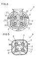
Fig. 4 is a schematic sectional view taken along line 4-4 inFig. 2 ; -
Fig. 5 is a schematic sectional view taken along line 5-5 inFig. 2 ; -
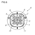
Fig. 6 is a schematic sectional view taken along line 6-6 inFig. 2 ; -
Fig. 7 is a schematic partial plan view ofFig. 6 ; and -
Fig. 8 is a schematic explanatory drawing for explaining the operation of blades of the kneader inFig. 1 . - Hereunder, embodiments of a kneader of the invention will be explained with reference to the accompanying drawings.
- In
Figs. 1-8 , the reference alphabet N represents a kneader, and the kneader N is used for kneading papermaking materials such as, for example, used paper and waste sheets. Specifically, the kneader N kneads them in such a way that ink materials (undispersive ink such as UV and toner) which are mixed into a recycled pulp are separated from the pulp, and acasing 3 is supported on a base 1 through supportingmembers 2. - The
casing 3 includes a papermaking material supply opening 3a and apapermaking material outlet 3b which is located lower than the papermaking material supply opening 3a. Inside thecasing 3, as shown inFigs. 4-6 , first, second, third and fourthrotational shafts fourth blades rotational shafts Figs. 4-6 , the firstrotational shaft 4 and the second rotational shaft 5 are the same height (for example, the height from the bottom surface of the casing 1 is the same) and in parallel with each other. The thirdrotational shaft 6 and the fourthrotational shaft 7 are the same height (for example, the height from the bottom surface of the casing 1 is the same) and in parallel with each other. The thirdrotational shaft 6 is located under the firstrotational shaft 4 and the fourthrotational shaft 7 is located under the second rotational shaft 5, respectively. Therefore, the volume of the space, where the papermaking material is processed, can be increased without increasing the installation space of the bottom portion of the kneader N. - Incidentally, in the embodiments, although a pair of rotational shafts (4 and 5, or 6 and 7) are arranged in two levels, the invention is not limited to the embodiments described hereinabove, and can have more than two levels as long as at least the first, second, third and fourth
rotational shafts casing 3. Also, overheated steam is supplied to thecasing 3 through an overheated steam supply channel which is not shown in the figures. - Each
first blade 8 is configured by, for example, first feed blades (feed arbitrary or feed guide blades) 81 and first return blades (return arbitrary or return guide blades) 82 which are alternately attached to the first rotational shaft 4 (refer toFig. 7 ). Thefirst feed blades 81 guide the papermaking materials from a papermaking material supply opening 3a side to apapermaking material outlet 3b side. Conversely, thefirst return blades 82 guide the papermaking materials to return from thepapermaking material outlet 3b side to the papermaking material supply opening 3a side. - More specifically, the
first feed blades 81 and thefirst return blades 82 have tube members X attached to the firstrotational shaft 4; and blades Y made of a bar-like member with a wing-shaped cross section which are attached to the tube members X. The wing-shaped blades Y have a tapered shape from back end portions b to front end portions a, and flat surfaces c which are parallel to end surfaces X1 of the tube members X are formed along the blades Y. Thefirst feed blades 81 are attached to the firstrotational shaft 4 in such a way that the flat surfaces c face the upstream side of the papermaking materials, and thefirst return blades 82 are attached to the firstrotational shaft 4 in such a way that the flat surfaces c face the downstream side of the papermaking materials, respectively. In addition, the front end portions a are located in front of the back end portions b relative to a rotational direction of the blades Y. - Each
second blade 9 is configured by, for example, second feed blades (feed arbitrary or feed guide blades) 91 and second return blades (return arbitrary or return guide blades) 92 which are alternately attached to the second rotational shaft 5 (refer toFig. 7 ). As in the case of thefirst feed blades 81, the second feed blades 91 guide the papermaking materials from the papermaking material supply opening 3a side to thepapermaking material outlet 3b side. Conversely, thesecond return blades 92 guide the papermaking materials to return from thepapermaking material outlet 3b side to the papermaking material supply opening 3a side. - More specifically, the second feed blades 91 and the
second return blades 92 have the tube members X attached to the second rotational shaft 5; the blades Y made of a bar-like member with a wing-shaped cross section which are attached to the tube members X. The wing-shaped blades Y have a tapered shape from back end portions b to front end portions a, and flat surfaces c which are parallel to the end surfaces X1 of the tube members X are formed along the blades Y. The second feed blades 91 are attached to the second rotational shaft 5 in such a way that the flat surfaces c face the upstream side of the papermaking materials, and thesecond return blades 92 are attached to the second rotational shaft 5 in such a way that the flat surfaces c face the downstream side of the papermaking materials, respectively. In addition, the front end portions a are located in front of the back end portions b relative to the rotational direction of the blades Y. - Each
third blade 10 is configured by, for example, third feed blades (feed arbitrary or feed guide blades) 101 and third return blades (return arbitrary or return guide blades) 102 which are alternately attached to the third rotational shaft 6 (refer toFig. 7 ). More specifically, thethird feed blades 101 and thethird return blades 102 have tube members X attached to the thirdrotational shaft 6; and blades Y made of a bar-like member with a wing-shaped cross section which are attached to third tube members X. The wing-shaped blades Y have a tapered shape from back end portions b to front end portions a, and flat surfaces c which are parallel to the end surfaces X1 of the tube members X are formed along the blades Y. Thethird feed blades 101 are attached to the thirdrotational shaft 6 in such a way that the flat surfaces c face the upstream side of the papermaking materials, and thethird return blades 102 are attached to the thirdrotational shaft 6 in such a way that the flat surfaces c face the downstream side of the papermaking materials, respectively, In addition, the front end portions a are located in front of the back end portions b relative to the rotational direction of the blades Y. - Each
fourth blade 11 is configured by, for example, fourth feed blades (feed arbitrary or feed guide blades) 111 and fourth return blades (return arbitrary or return guide blades) 112 which are alternately attached to the fourth rotational shaft 7 (refer toFig. 7 ) . More specifically, the fourth feed blades 111 and the fourth return blades 112 have the tube members X attached to the fourthrotational shaft 7; and the blades Y made of a bar-like member with a wing-shaped cross section which are attached to the tube members X. The wing-shaped blades Y have a tapered shape from back end portions b to front end portions a, and flat surfaces c which are parallel to the end surfaces X1 of the tube members X are formed along the blades Y. The fourth feed blades 111 are attached to the fourthrotational shaft 7 in such a way that the flat surfaces c face the upstream side of the papermaking materials, and the fourth return blades 112 are attached to the fourthrotational shaft 7 in such a way that the flat surfaces c face the downstream side of the papermaking materials, respectively. In addition, the front end portions a are located before the back end portions b relative to the rotational direction of the blades Y. - As mentioned above, the blades have the tube members X attached to the rotational shafts and the blades Y attached to the tube members X. The blades Y have a tapered shape from the back end portions b to the front end portions a, and the flat surfaces c which are parallel to the end surfaces X1 of the tube members X are formed along the blades Y. By turning directions of the blades Y alternately, the feed blades and the return blades can be shared and also easily configured, In addition, M1, M2, M3, M4 shown in
Fig. 4 represent key grooves, and K1, K2, K3, K4 represent keys. By passing the keys K1, K2, K3, K4 through the key grooves M1, M2, M3, M4, the first, second, third and fourthrotational shafts fourth blades - The first
rotational shaft 4 and the second rotational shaft 5 rotate differently with each other through afirst motor 12, achain 13 and a gear which is not shown in the figure (refer toFig. 1 ). The thirdrotational shaft 6 and the fourthrotational shaft 7 rotate differently with each other through asecond motor 14, achain 15 and a gear which is not shown in the figure. As shown inFig. 6 , for example, rotational directions of the firstrotational shaft 4 and the thirdrotational shaft 6 are clockwise, and rotational directions of the second rotational shaft 5 and the fourthrotational shaft 7 are counterclockwise. Incidentally, in the embodiment, the rotational directions of the firstrotational shaft 4 and the thirdrotational shaft 6 are clockwise and the rotational directions of the second rotational shaft 5 and the fourthrotational shaft 7 are counterclockwise. However, the rotational directions and rotational frequency of the first, second, third and fourthrotational shafts Fig. 5 , in the embodiment, the first, second, third andfourth blades rotational shafts blades - Under the papermaking material supply opening 3a, screws 21, 22, 23, 24 sending the papermaking materials are respectively provided on the side of the first
rotational shaft 4 and the second rotational shaft 5 and on the side of the thirdrotational shaft 6 and the fourth rotational shaft 7 (refer toFigs. 1-4 ). An opening-and-closinglid 30 which opens and closes thepapermaking material outlet 3b is provided in thepapermaking material outlet 3b, and thepapermaking material outlet 3b is closed by the opening-and-closinglid 30, so that a constant amount of papermaking materials is accumulated inside thecasing 3 and kneaded. After the papermaking materials inside thecasing 3 are kneaded, the opening-and-closinglid 30 is opened and the kneaded papermaking materials are discharged to the outside of thecasing 3. - Therefore, if the papermaking materials such as the used paper and the waste sheet are supplied from the papermaking material supply opening 3a in a state where the
papermaking material outlet 3b is closed by the opening-and-closinglid 30, the papermaking materials are guided to a firstrotational shaft 4 and second rotational shaft 5 side by thescrews screws rotational shaft 6 and secondrotational shaft 7 side by thescrews 23, 24, respectively. The papermaking materials which were guided to the firstrotational shaft 4 and second rotational shaft 5 side are kneaded by thefirst blade 8 and thesecond blade 9, and the papermaking materials which were guided to the thirdrotational shaft 6 and fourthrotational shaft 7 side are kneaded by thethird blade 10 and thefourth blade 11, respectively (refer toFig. 6 ). Especially, thefirst feed blade 81 and thesecond return blade 92; thefirst return blade 82 and the second feed blade 91; thethird feed blade 101 and the fourth return blade 112; and thethird return blade 102 and the fourth feed blade 111 are arranged to face each other, respectively. Accordingly, the papermaking materials do not pass through smoothly, so that the papermaking materials stay longer inside thecasing 3 and are kneaded more by the blades. As a result, the papermaking materials are kneaded more reliably (refer toFig. 8 ) . - In addition, when the papermaking materials which passed between the pair of first
rotational shaft 4 and second rotational shaft 5 move between the pair of thirdrotational shaft 6 and fourthrotational shaft 7, the papermaking materials are kneaded by thefirst blade 81, thethird blade 101, the second blade 91 and the fourth blade 111. More specifically, the papermaking materials which are processed are also kneaded by thefirst blade 81 and thethird blade 101; and the second blade 91 and the fourth blade 111 in addition to by thefirst blade 81 and the second blade 91; and thethird blade 101 and the fourth blade 111 while the papermaking materials reach thepapermaking material outlet 3b. As a result, the kneading effect can be also increased (refer toFig. 6 ). As mentioned above, the papermaking materials such as the used paper and the waste sheet are kneaded by the kneader N, the used paper and the waste sheet are rubbed, and ink materials which are mixed in the papermaking materials (the ink materials are also subdivided) can be separated from the pulp. Also, the rest of the process can be processed, for example, the ink materials can be eliminated from the pulp by a flotator and so on.
Claims (7)
- A kneader (N) comprising:a) a casing (3) having a papermaking material supply opening (3a) and a papermaking material outlet (3b) located below the papermaking material supply opening (3a);b) at least first, second, third and fourth rotational shafts (4, 5, 6, 7) provided inside the casing (3);c) first blades (8) attached to the first rotational shaft (4); second blades (9) attached to the second rotational shaft (5); third blades (10) attached to the third rotational shaft (6); and fourth blades (11) attached to the fourth rotational shaft (7); whereind) the first rotational shaft (4) and the second rotational shaft (5) are disposed at the same height and are arranged parallel to each other, the third rotational shaft (6) and the fourth rotational shaft (7) are disposed at the same height and are arranged parallel to each other, the third rotational shaft (6) is located below the first rotational shaft (4), and the fourth rotational shaft (7) is located below the second rotational (5) shaft;
characterised in thate) the first blades (8) comprise first feed blades (81) and first return blades (82) which are alternately attached to the first rotational shaft (4); the second blades (9) comprise second feed blades (91) and second return blades (92) which are alternately attached to the second rotational shaft (5); the third blades (10) comprise third feed blades (101) and third return blades (102) which are alternately attached to the third rotational shaft (6); and the fourth blades (11) comprise fourth feed blades (111) and fourth return blades (112) which are alternately attached to the fourth rotational shaft (7). - A kneader (N) according to claim 1, wherein the first feed blades (81) and the second return blades (92) face each other; the first return blades (82) and the second feed blades (91) face each other; the third feed blades (101) and the fourth return blades (112) face each other; the third return blades (102) and the fourth feed blades (111) face each other; the first feed blades (81) and the third return blades (102) face each other; the first return blades (82) and the third feed blades (101) face each other; the second feed blades (91) and the fourth return blades (112) face each other; and the second return blades (92) and the fourth feed blades (111) face each other.
- A kneader (N) according to claim 2, wherein each of the first feed blade (81) and the first return blade (82) includes a tube member (X) attached to the first rotational shaft (4), a blade (Y) attached to the tube member (X), each blade (Y) having a tapered shape from a back end portion (b) to a front end portion (a) thereof, and a flat surface (c) parallel to an end surface of the tube member (X) along the blade (Y); the first feed blade (81) is attached to the first rotational shaft (4) in such a way that the flat surface (c) faces an upstream side of flow of the papermaking material; and the first return blade (82) is attached to the first rotational shaft (4) in such a way that the flat surface (c) faces a downstream side of the flow of the papermaking material.
- A kneader (N) according to claim 3, wherein each of the second feed blade (91) and the second return blade (92) include a tube member (X) attached to the second rotational shaft (5), a blade (Y) attached to the tube member (X), each blade (Y) having a tapered shape from a back end portion (b) to a front end portion (a) thereof, and a flat surface (c) parallel to the end surface of the tube member (X) along the blade (Y); the second feed blade (91) is attached to the second rotational shaft (5) in such a way that the flat surface (c) faces the upstream side of the flow of the papermaking material; and the second return blade (92) is attached to the second rotational shaft (5) in such a way that the flat surface (c) faces the downstream side of the flow of the papermaking material.
- A kneader (N) according to claim 4, wherein each of the third feed blade (101) and the third return blade (102) includes a tube member (X) attached to the third rotational shaft (6), a blade (Y) attached to the tube member (X), each blade (Y) having a tapered shape from a back end portion (b) to a front end portion (a) thereof, and a flat surface (c) parallel to the end surface of the tube member (X) along the blade (Y); the third feed blade (101) is attached to the third rotational shaft (6) in such a way that the flat surface (c) faces the upstream side of the flow of the papermaking material; and the third return blade (102) is attached to the third rotational shaft (6) in such a way that the flat surface (c) faces the downstream side of the flow of the papermaking material.
- A kneader (N) according to claim 5, wherein each of the fourth feed blade (111) and the fourth return blade (112) includes a tube member (X) attached to the fourth rotational shaft (7), a blade (Y) attached to the tube member (X), each blade (Y) having a tapered shape from a back end (6) portion to a front end portion (a) thereof, and a flat surface (c) parallel to the end surface of the tube member (X) along the blade (Y); the fourth feed blade (111) is attached to the fourth rotational shaft (7) in such a way that the flat surface (c) faces the upstream side of the flow of the papermaking material; and the fourth return blade (112) is attached to the fourth rotational shaft (7) in such a way that the flat surface (c) faces the downstream side of the flow of the papermaking material.
- A method for kneading a papermaking material said method comprising the steps of:a) feeding the papermaking material in a casing (3) having a papermaking material supply opening (3a) and a papermaking material outlet (3b) located below the papermaking supply opening (3a); andb) processing the papermaking material using at least four rotational shafts (4, 5, 6, 7) provided inside the casing (3);c) wherein each rotational shaft (4, 5, 6, 7) comprises blades (8, 9, 10, 11) attached to the respective shaft for processing the papermaking material, and
characterised in thatd) the blades (8, 9, 10, 11) comprise feed blades (81, 91, 101, 111) which feed the papermaking material through the casing and return blades (82, 92, 102, 112) which prolong the processing time of the papermaking material in the casing (3), wherein the feed blades (81, 91, 101, 111) and the return blades (82, 92, 102, 112) are alternately attached to the respective rotational shaft (4, 5, 6, 7).
Applications Claiming Priority (1)
| Application Number | Priority Date | Filing Date | Title |
|---|---|---|---|
| JP2006267501A JP4724632B2 (en) | 2006-09-29 | 2006-09-29 | Kneader |
Publications (2)
| Publication Number | Publication Date |
|---|---|
| EP1905506A1 EP1905506A1 (en) | 2008-04-02 |
| EP1905506B1 true EP1905506B1 (en) | 2010-07-28 |
Family
ID=38846915
Family Applications (1)
| Application Number | Title | Priority Date | Filing Date |
|---|---|---|---|
| EP07116345A Not-in-force EP1905506B1 (en) | 2006-09-29 | 2007-09-13 | Kneader for kneading a papermaking material, and method for kneading the same |
Country Status (9)
| Country | Link |
|---|---|
| US (1) | US7624939B2 (en) |
| EP (1) | EP1905506B1 (en) |
| JP (1) | JP4724632B2 (en) |
| KR (1) | KR101229027B1 (en) |
| CN (1) | CN101153470B (en) |
| CA (1) | CA2602881C (en) |
| DE (1) | DE602007008021D1 (en) |
| ES (1) | ES2349316T3 (en) |
| TW (1) | TW200825247A (en) |
Cited By (1)
| Publication number | Priority date | Publication date | Assignee | Title |
|---|---|---|---|---|
| RU2605910C2 (en) * | 2015-04-02 | 2016-12-27 | Егор Владимирович Кулигин | Device for preparation of moulding mixture for making articles from composite material (versions) |
Families Citing this family (16)
| Publication number | Priority date | Publication date | Assignee | Title |
|---|---|---|---|---|
| DE102008048580B4 (en) * | 2008-09-23 | 2014-08-21 | List Holding Ag | Device for carrying out mechanical, chemical and / or thermal processes |
| JP5322731B2 (en) * | 2009-03-30 | 2013-10-23 | 株式会社神戸製鋼所 | Closed kneader |
| CA132115S (en) * | 2009-04-03 | 2011-03-10 | Satake Eng Co Ltd | Milling screening machine |
| JP4542605B1 (en) | 2009-04-15 | 2010-09-15 | 株式会社神戸製鋼所 | Closed kneading machine and kneading rotor |
| IT1399428B1 (en) * | 2010-04-07 | 2013-04-16 | Revelin Evaristo & Figli Snc | CONSTANT FLOW CONTINUOUS MIXER |
| IT1403080B1 (en) * | 2010-06-10 | 2013-10-04 | Galvanin | APPARATUS FOR THE PRODUCTION OF MOZZARELLA FILATA OR OTHER SOFT CASEARY PRODUCT, PARTICULARLY FOR PIZZAS, PANINI, PIADINE ETC., STARTING FROM FROZEN RAW MATERIAL. |
| ITMI20120305A1 (en) * | 2012-02-28 | 2013-08-29 | Fava S P A | "PERFECTED MIXING TREE FOR CENTRIFUGAL FOOD MIXER" |
| FR2987546B1 (en) * | 2012-03-05 | 2015-06-05 | Vmi | CONTINUOUS PETRIER MACHINE FOR A PASTA FOR BAKERY OR PASTRY PREPARATION SUCH AS MIE BREAD, AND FRASER FOR SUCH A MACHINE |
| WO2014023738A2 (en) * | 2012-08-08 | 2014-02-13 | List Holding Ag | Method for treating viscous pasty compositions |
| CN104631172B (en) * | 2015-03-02 | 2017-01-11 | 济南大学 | Double-rotor hedging and inter-twisting type pulper |
| US11389775B2 (en) * | 2016-04-25 | 2022-07-19 | Young Ho Bok | Stirrer comprising two rotating shafts having intersecting stirring blades capable of rotating symmetrically and rotating in identical direction and stirring method |
| KR20200003384A (en) * | 2017-05-04 | 2020-01-09 | 제이-로르 인터내셔널 인코포레이티드 | Tiltable compounder |
| CN110368859B (en) * | 2019-06-10 | 2022-04-12 | 湖南川渝食品有限公司 | Equipment and method for blending multiple seasonings according to proportion |
| CN113663567A (en) * | 2020-05-13 | 2021-11-19 | 中石化石油工程技术服务有限公司 | Dust-free environment-friendly adding device for temporary fiber plugging agent |
| CN114474649B (en) * | 2022-02-11 | 2022-11-04 | 安徽戴家工艺有限公司 | Wood-plastic board forming equipment and forming process |
| DE102022117107A1 (en) * | 2022-07-08 | 2024-01-11 | Harburg-Freudenberger Maschinenbau Gmbh | Mixer for polymer processing and method of operating a mixer |
Family Cites Families (20)
| Publication number | Priority date | Publication date | Assignee | Title |
|---|---|---|---|---|
| GB191220182A (en) * | 1912-09-04 | 1913-05-15 | Casimir Wurster | Breaking or Pulping Engine for use in the Manufacture of Paper and Wood-pulp. |
| GB191320182A (en) | 1913-09-06 | 1914-08-20 | Stanley Marshall | Improvements in or relating to Apparatus for Conveying and Loading Coals and similar Materials. |
| GB262270A (en) | 1925-12-10 | 1926-12-09 | Otto Charles Winestock | Improvements in and relating to the defibration of paper and the like |
| US2903192A (en) * | 1957-05-10 | 1959-09-08 | Robert A Clausen | Disposer for waste material |
| GB892506A (en) * | 1957-07-02 | 1962-03-28 | Calor & Sjoegren Ab | Apparatus for performing a working treatment on particulate or suspended material |
| US3454234A (en) * | 1964-01-22 | 1969-07-08 | Karl P Schoeppner | Blade combination for machines for chipping and shaving solid materials |
| DE1553134C3 (en) * | 1966-12-29 | 1976-12-02 | Metallgesellschaft Ag | SCREW CONVEYOR |
| FR2319737A1 (en) * | 1975-07-31 | 1977-02-25 | Creusot Loire | PAPER PULP MANUFACTURING PROCESS AND MACHINE |
| FR2436844A2 (en) * | 1978-09-19 | 1980-04-18 | Creusot Loire | Converting lignocellulose material into fibre pulp - for paper-making, by introducing bleach whilst the lignocellulose is being broken down |
| DK139092B (en) * | 1976-10-05 | 1978-12-18 | Jens Axel Freudendahl | Apparatus for homogenizing straw cutters. |
| SE408920B (en) * | 1977-12-06 | 1979-07-16 | Mo Och Domsjoe Ab | DEVICE FOR DEBIBRYING AND CONDITIONING CELLULOSE MATERIAL |
| JPS60156198U (en) | 1984-03-23 | 1985-10-17 | 森實 美津夫 | Pulp disintegration equipment |
| JPH03185188A (en) * | 1989-12-14 | 1991-08-13 | Iwashina Seisakusho:Kk | Kneader for making paper |
| US5402950A (en) * | 1994-02-08 | 1995-04-04 | Concept Products Corporation | Portable shredding machine |
| IT1280070B1 (en) * | 1995-06-05 | 1997-12-29 | Comer Spa | WRAPPER FOR PAPER PASTE |
| JP3499414B2 (en) * | 1996-12-24 | 2004-02-23 | 株式会社神戸製鋼所 | Twin screw kneader |
| JP2000033615A (en) | 1998-07-15 | 2000-02-02 | Kitagawa Iron Works Co Ltd | Continuous mixer and kneading method using the same |
| JP4064308B2 (en) * | 2002-07-17 | 2008-03-19 | 鈴鹿エンヂニヤリング株式会社 | Rubber kneader |
| JP2005089915A (en) | 2003-09-18 | 2005-04-07 | Hitachi Constr Mach Co Ltd | Waste paper crusher and sludge treatment system equipped with the same |
| JP2005226206A (en) | 2004-02-12 | 2005-08-25 | Jiro Kobori | Machine for kneading waste paper and water |
-
2006
- 2006-09-29 JP JP2006267501A patent/JP4724632B2/en not_active Expired - Fee Related
-
2007
- 2007-07-31 TW TW096127991A patent/TW200825247A/en not_active IP Right Cessation
- 2007-09-04 KR KR1020070089496A patent/KR101229027B1/en not_active Expired - Fee Related
- 2007-09-13 ES ES07116345T patent/ES2349316T3/en active Active
- 2007-09-13 EP EP07116345A patent/EP1905506B1/en not_active Not-in-force
- 2007-09-13 US US11/898,546 patent/US7624939B2/en not_active Expired - Fee Related
- 2007-09-13 DE DE602007008021T patent/DE602007008021D1/en active Active
- 2007-09-14 CA CA2602881A patent/CA2602881C/en not_active Expired - Fee Related
- 2007-09-24 CN CN2007101618247A patent/CN101153470B/en not_active Expired - Fee Related
Cited By (1)
| Publication number | Priority date | Publication date | Assignee | Title |
|---|---|---|---|---|
| RU2605910C2 (en) * | 2015-04-02 | 2016-12-27 | Егор Владимирович Кулигин | Device for preparation of moulding mixture for making articles from composite material (versions) |
Also Published As
| Publication number | Publication date |
|---|---|
| CA2602881A1 (en) | 2008-03-29 |
| KR20080029789A (en) | 2008-04-03 |
| CN101153470A (en) | 2008-04-02 |
| KR101229027B1 (en) | 2013-02-04 |
| JP4724632B2 (en) | 2011-07-13 |
| EP1905506A1 (en) | 2008-04-02 |
| US7624939B2 (en) | 2009-12-01 |
| CA2602881C (en) | 2013-01-15 |
| US20080078853A1 (en) | 2008-04-03 |
| TW200825247A (en) | 2008-06-16 |
| TWI355443B (en) | 2012-01-01 |
| JP2008088569A (en) | 2008-04-17 |
| CN101153470B (en) | 2011-09-07 |
| DE602007008021D1 (en) | 2010-09-09 |
| ES2349316T3 (en) | 2010-12-29 |
Similar Documents
| Publication | Publication Date | Title |
|---|---|---|
| CA2602881C (en) | Kneader | |
| EP1123731B1 (en) | Mixing apparatus | |
| CA2480891C (en) | Pulp flaker | |
| US7601243B2 (en) | Method for conveying, mixing, and leveling dewatered pulp prior to drying | |
| JP4167951B2 (en) | Biaxial mixer for ready-mixed concrete | |
| US5738439A (en) | Mixing apparatus | |
| US20040008574A1 (en) | Propeller for stirring solid-in-liquid suspensions in a treatment tank | |
| KR20260037023A (en) | Stirring blade, stirring device, stirring method | |
| SK160399A3 (en) | Rotor for machines mixing elastomers and the like, having a variable flange or flight angle | |
| FI66441B (en) | ANORDNING FOER BEHANDLING AV ETT FIBRIGT MATERIAL | |
| CN215714242U (en) | High-efficient scattered pulp grinder of formula is smashed to multistage with change bucket | |
| CN218423220U (en) | Novel broken size mixing machine of coal slime filter cake | |
| JP7416589B2 (en) | multi-stage screen | |
| CN114515635A (en) | Crushing device | |
| CN210450255U (en) | PET board recycling and reprocessing system | |
| US3417933A (en) | Pulper | |
| CN216756675U (en) | Paper shredder core capable of continuously shredding paper for multiple times and paper shredder | |
| CN218466195U (en) | Energy-efficient upper transmission birotor hydraulic decomposition and separation equipment | |
| CN218232931U (en) | Energy-efficient birotor water conservancy decomposes splitter | |
| CN219002880U (en) | Ultrasonic homogenizing emulsifying device | |
| CN210613497U (en) | Cement raw material homogenizing device | |
| CN210758287U (en) | Hammer type chipping machine | |
| CN210332345U (en) | High-efficiency glue mixer | |
| CN116180478A (en) | Utilize straw automation papermaking device | |
| RU101041U1 (en) | CAVITATOR |
Legal Events
| Date | Code | Title | Description |
|---|---|---|---|
| PUAI | Public reference made under article 153(3) epc to a published international application that has entered the european phase |
Free format text: ORIGINAL CODE: 0009012 |
|
| AK | Designated contracting states |
Kind code of ref document: A1 Designated state(s): AT BE BG CH CY CZ DE DK EE ES FI FR GB GR HU IE IS IT LI LT LU LV MC MT NL PL PT RO SE SI SK TR |
|
| AX | Request for extension of the european patent |
Extension state: AL BA HR MK YU |
|
| RIN1 | Information on inventor provided before grant (corrected) |
Inventor name: ONIZAKI, TAKASHI Inventor name: AOKI, ISAO Inventor name: IWABUCHI, HISASHI Inventor name: SUGINO, MITSUHIRO Inventor name: AIKAWA, YOSHIHIKO |
|
| 17P | Request for examination filed |
Effective date: 20080417 |
|
| 17Q | First examination report despatched |
Effective date: 20080516 |
|
| AKX | Designation fees paid |
Designated state(s): DE ES FR GB IT |
|
| RTI1 | Title (correction) |
Free format text: KNEADER FOR KNEADING A PAPERMAKING MATERIAL, AND METHOD FOR KNEADING THE SAME |
|
| GRAP | Despatch of communication of intention to grant a patent |
Free format text: ORIGINAL CODE: EPIDOSNIGR1 |
|
| GRAS | Grant fee paid |
Free format text: ORIGINAL CODE: EPIDOSNIGR3 |
|
| GRAA | (expected) grant |
Free format text: ORIGINAL CODE: 0009210 |
|
| AK | Designated contracting states |
Kind code of ref document: B1 Designated state(s): DE ES FR GB IT |
|
| REG | Reference to a national code |
Ref country code: GB Ref legal event code: FG4D |
|
| REF | Corresponds to: |
Ref document number: 602007008021 Country of ref document: DE Date of ref document: 20100909 Kind code of ref document: P |
|
| REG | Reference to a national code |
Ref country code: ES Ref legal event code: FG2A Effective date: 20101216 |
|
| PLBE | No opposition filed within time limit |
Free format text: ORIGINAL CODE: 0009261 |
|
| STAA | Information on the status of an ep patent application or granted ep patent |
Free format text: STATUS: NO OPPOSITION FILED WITHIN TIME LIMIT |
|
| 26N | No opposition filed |
Effective date: 20110429 |
|
| REG | Reference to a national code |
Ref country code: DE Ref legal event code: R097 Ref document number: 602007008021 Country of ref document: DE Effective date: 20110429 |
|
| PGFP | Annual fee paid to national office [announced via postgrant information from national office to epo] |
Ref country code: DE Payment date: 20140922 Year of fee payment: 8 |
|
| PGFP | Annual fee paid to national office [announced via postgrant information from national office to epo] |
Ref country code: FR Payment date: 20140919 Year of fee payment: 8 Ref country code: GB Payment date: 20140919 Year of fee payment: 8 Ref country code: ES Payment date: 20140926 Year of fee payment: 8 |
|
| PGFP | Annual fee paid to national office [announced via postgrant information from national office to epo] |
Ref country code: IT Payment date: 20140930 Year of fee payment: 8 |
|
| REG | Reference to a national code |
Ref country code: DE Ref legal event code: R119 Ref document number: 602007008021 Country of ref document: DE |
|
| PG25 | Lapsed in a contracting state [announced via postgrant information from national office to epo] |
Ref country code: IT Free format text: LAPSE BECAUSE OF NON-PAYMENT OF DUE FEES Effective date: 20150913 |
|
| GBPC | Gb: european patent ceased through non-payment of renewal fee |
Effective date: 20150913 |
|
| REG | Reference to a national code |
Ref country code: FR Ref legal event code: ST Effective date: 20160531 |
|
| PG25 | Lapsed in a contracting state [announced via postgrant information from national office to epo] |
Ref country code: GB Free format text: LAPSE BECAUSE OF NON-PAYMENT OF DUE FEES Effective date: 20150913 Ref country code: DE Free format text: LAPSE BECAUSE OF NON-PAYMENT OF DUE FEES Effective date: 20160401 |
|
| PG25 | Lapsed in a contracting state [announced via postgrant information from national office to epo] |
Ref country code: FR Free format text: LAPSE BECAUSE OF NON-PAYMENT OF DUE FEES Effective date: 20150930 |
|
| REG | Reference to a national code |
Ref country code: ES Ref legal event code: FD2A Effective date: 20161207 |
|
| PG25 | Lapsed in a contracting state [announced via postgrant information from national office to epo] |
Ref country code: ES Free format text: LAPSE BECAUSE OF NON-PAYMENT OF DUE FEES Effective date: 20150914 |