EP1905485A2 - Fire extinguishing equipment for mounting on a pressurized container - Google Patents
Fire extinguishing equipment for mounting on a pressurized container Download PDFInfo
- Publication number
- EP1905485A2 EP1905485A2 EP07388069A EP07388069A EP1905485A2 EP 1905485 A2 EP1905485 A2 EP 1905485A2 EP 07388069 A EP07388069 A EP 07388069A EP 07388069 A EP07388069 A EP 07388069A EP 1905485 A2 EP1905485 A2 EP 1905485A2
- Authority
- EP
- European Patent Office
- Prior art keywords
- fire
- container
- valve
- appliance according
- detector
- Prior art date
- Legal status (The legal status is an assumption and is not a legal conclusion. Google has not performed a legal analysis and makes no representation as to the accuracy of the status listed.)
- Withdrawn
Links
Images


Classifications
-
- A—HUMAN NECESSITIES
- A62—LIFE-SAVING; FIRE-FIGHTING
- A62C—FIRE-FIGHTING
- A62C37/00—Control of fire-fighting equipment
- A62C37/08—Control of fire-fighting equipment comprising an outlet device containing a sensor, or itself being the sensor, i.e. self-contained sprinklers
- A62C37/10—Releasing means, e.g. electrically released
- A62C37/11—Releasing means, e.g. electrically released heat-sensitive
-
- A—HUMAN NECESSITIES
- A62—LIFE-SAVING; FIRE-FIGHTING
- A62C—FIRE-FIGHTING
- A62C13/00—Portable extinguishers which are permanently pressurised or pressurised immediately before use
- A62C13/62—Portable extinguishers which are permanently pressurised or pressurised immediately before use with a single permanently pressurised container
- A62C13/64—Portable extinguishers which are permanently pressurised or pressurised immediately before use with a single permanently pressurised container the extinguishing material being released by means of a valve
Definitions
- the invention relates to a fire extinguishing appliance for mounting on a pressurized container, said container comprising a bottle which contains fire extinguishing particles in liquid or gaseous state, and a valve through which the fire extinguishing particles flow out of the container, said appliance comprising a release element which may be broken down by thermal or mechanical impact, an arm which is present on the valve, and a spring which is fixedly mounted on the bracket and presses against the arm.
- the fire is detected by the detection device, and then the valves of the pressurized bottles are activated automatically, and the extinguishant is distributed automatically via the nozzles, which are arranged in the fire-protected area.
- the object of the present invention is to provide a more expedient solution to the above-mentioned problems for the fire protection of small and medium-sized installations.
- the release element keeps the spring tensioned and may be broken down by heat and/or a mechanical impact.
- the arm is connected directly with the valve on the pressurized container.
- a nozzle housing may be mounted on the valve so that the arm is connected with the nozzle housing, as stated in claim 2.
- the nozzle housing is a body with a continuous cavity having an inlet opening with a seat and an outlet opening, on which a standard container containing a compressed gas and an extinguishant and a standard bottle valve is mounted, so that the seat of the inlet hole and the bottle valve match and form a leakage-proof connection at mutual contact.
- the invention operates in that the release element is broken down when it is subjected to heat or a mechanical impact.
- the tensioned spring is released, whereby the spring supplies its spring force to the arm, which in turn presses down on the valve, whereby the fire extinguishing particles are released to the surroundings and are distributed at the scene of the fire via a hose or a pipe, as stated in claim 3.
- the continuous cavity of the nozzle housing is configured as an inlet opening having a seat connected with a pipe or a hose arranged on the valve, and the outlet opening of the body is configured as a nozzle opening, it is ensured that the compressed gas in the container is supplied in precise drop sizes and in a precise distribution at the scene of the fire.
- the release element is configured with a liquid-filled glass bulb or a meltable link or a shape memory element which is broken down by heat, and the release element is arranged surrounded by an electrical source of heat in the form of a hot wire or another type of a heating element which is heated by an electrical source of energy controlled via a thermocouple or another electrical fire detection device, the following is achieved:
- thermocouple When a fire affects the thermocouple or another electrical fire detection device, electric current is supplied to the heaf source which surrounds the heat-sensitive release element. When the element is subjected to heat or a mechanical impact, it is broken down. Hereby, the tensioned spring is released, whereby the spring supplies its spring force through the arm on the nozzle housing, whereby the inlet of the nozzle housing via its seat is pressed against the valve of the container, thereby forming a leakage-proof connection between the inlet opening and the valve, which presses the valve of the container down into the container, thereby causing the container valve to open to the container cavity, whereby the compressed gas in the container presses the contents of extinguishant in the container via the container valve and the inlet opening of the body into the continuous cavity and out of the outlet opening of the body, from which the extinguishant is distributed.
- the appliance may be provided with a mechanical device for manual release of the fire extinguishing appliance.
- the mechanical device consists of a holder, which accommodates a piston in the form of a rod with an axial direction perpendicular to the longitudinal axis of the release element, and with an axial movement toward the release element, which is locked by a pin, lock or another manually openable locking unit.
- the locking unit which prevents the piston from contacting the release element, may be opened manually.
- the piston is affected manually for breaking down the release element, whereby the tensioned spring is released and supplies its spring force to the nozzle housing, whereby the inlet of the nozzle housing via its seat is pressed against the valve of the container, thereby creating a leakage-proof connection between the inlet opening and the valve, which presses the valve of the container down into the container, causing the container valve to open to the container cavity, following which the compressed gas in the container presses the contents of extinguishant in the container via the valve and the inlet opening of the body into the nozzle housing and out of the outlet opening of the body, from which the extinguishant is distributed.
- the nozzle housing may be configured with an inlet opening having a seat with a connection to a cavity consisting of a pipe or a hose.
- the outlet opening of the nozzle housing may be configured as a cylindrical cavity with a constriction at the outlet.
- a pipe member may be positioned in the cylindrical cavity.
- the pipe member consists of a hollow shaft with a bulge.
- the diameter of the bulge is larger than the diameter of the outlet constriction of the cylindrical cavity in the nozzle housing.
- the pipe member has a cylindrical face with a cross-sectional area which is smaller than the constriction of the nozzle housing.
- the cylindrical face extends through the constriction of the nozzle housing and ends in a nozzle opening.
- the electrical connection to the fire sensor and the hose or pipe of the continuous cavity is enclosed by a common screen in the form of a pipe or a hose ending in a housing, in which the fire sensor in the form of a thermocouple or a heat-sensitive electrical resistor or another form of electrical fire detector is arranged, and whose open end is closed by a sheet or a foil.
- the pressure of the extinguishant causes the pipe member in the nozzle housing to be pressed out of the cavity until the bulge engages the constriction in the outlet opening and thereby opens the sheet or breaks the foil, whereby the extinguishant is supplied to the scene of the fire from the same device as has also detected the fire, and as was hermetically sealed against external vapours and contaminants up to the release of the appliance.
- the fire detector device When the fire detector device is provided with a thermocouple and/or a thermal resistor which is connected to an electronic circuit having two thermal set points, each of which is connected to an electrical relay, and where the relay to the lowest temperature set point is connected to an alarm circuit and/or a power supply or a control circuit for the installation which is fire-protected by the appliance, and the relay to the highest temperature set point is connected to the power supply to a heating element which surrounds the thermal release element, it is ensured that, in case of superheating and a fire in the installation, the fire extinguishing appliance according to the invention first activates an alarm and/or interrupts the current to the installation, and then, if the temperature increases additionally, supplies a current to the heating element which surrounds the heat-sensitive element, following which this is broken down, and the extinguishing appliance is activated, as described previously.
- the fire detector device consists of two fire detectors, where the one detector is a smoke detector or a flame detector, and where the other detector is a heat detector, and where the first detector is connected to a relay connected to an alarm circuit and/or a power supply or a control circuit for the installation as well as a switch connected to the heat detector circuit, and where the heat detector circuit is connected to a time/temperature differential circuit having a pre-set temperature/time ratio which is connected to the heating element.
- the fire extinguishing appliance sounds an alarm via the alarm relay and/or interrupts the current to the installation as well as connects the heat detection circuit electrically.
- the release relay of the appliance is activated, thereby providing current to the heating element which surrounds the heat-sensitive release element, following which the appliance is automatically released, as described previously.
- a system of electrical resistance wires may be mounted on the circumference of the pressurized container, whose electrical resistance depends on the longitudinal expansion and/or the pull in the wires and thereby on the expansion of the surface of the pressurized container, and this resistance system may moreover be connected to an alarm relay output and/or another form of alarm system, optionally via an electrical control system. Since the expansion of the pressurized container depends on the current pressure in the container, the invention advantageously provides a very simple method of automatically monitoring the pressure in the container, and this method is not exacting in terms of space, does not require visual monitoring, and does not constitute a potential risk of leakage.
- pressure-sensitive chips or other pressure-sensitive elements may be used, which may be mounted on the outer side of the pressurized container or in contact faces between the pressurized container and its holding bracket.
- Figure 1 shows an example of the invention, which consists of a frame 10 in which a gas pressurized standard container 6 filled with an extinguishant is disposed.
- the opening of the container is closed by a standard container valve, which is activated via a valve pipe 5.
- a nozzle housing 8 is provided in extension of the valve pipe 5, having a continuous cavity with an inlet opening 7 having a seat which fits the valve pipe 5, and an outlet opening 4.
- An arm 2 is provided in extension of the nozzle housing 8, said arm being held at a point 9 with contact to the frame 10, and being supported by a release element 3 in the form of a liquid-filled glass bulb, a meltable link or a shape memory alloy.
- a tensioned compression spring 1 is provided in extension of the arm 2, said spring supplying a spring force to the arm 2, which is supported by the release element 3 and a point 9 in the frame.
- Figure 2 shows an example of the invention shown in fig. 1, where the release element 3 is broken.
- the spring force from the biased spring 1 is transferred via the arm 2 to the nozzle housing 8, whereby the spring force presses the nozzle housing 8 against the valve pipe 5, which is thereby pressed down and opens the valve of the container, whereby the gas pressure in the container presses the extinguishant via the valve pipe 5 into the continuous cavity in the nozzle housing 8 and out through the outlet opening 4, from which the extinguishant is distributed.
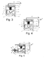
- Figure 3 shows an example of the invention shown in figure 1 and figure 2, where the release element 3 is released electrically via an electrical heating element 11, which is heated via an electrical control circuit 12 when a fire detector sensor 13 detects a fire or the heat from a fire.
- Figure 4 shows an example of the invention shown in figure 3, where the nozzle housing 8 is provided with a pipe or a hose 14 with an outlet opening 15.
- Figure 5 shows an example of the invention shown in figure 4 with manual, mechanical release, where a piston 17 is mounted on the frame 10, said piston having a lock 16 and a button 36 provided on a shaft which intersects the axis of the release member.
- the button 36 may be depressed, whereby the release element 3 is broken, and the appliance is released automatically.
- Figure 6 shows an example of the invention, where a container 33 having a valve pipe 34 is arranged in an automatic release apparatus, which consists of a seat 18 on a pipe 38 which is connected via a cup 56 with a compressed compression spring 39, which is kept compressed via a release element 25 surrounded by an electrical heating element 26, and which is kept in place by a screw 24, and a point 29.
- an automatic release apparatus which consists of a seat 18 on a pipe 38 which is connected via a cup 56 with a compressed compression spring 39, which is kept compressed via a release element 25 surrounded by an electrical heating element 26, and which is kept in place by a screw 24, and a point 29.
- the pipe 38 is connected via a second pipe 32 with a third pipe 30, which is connected with a hose 40, which is connected with a nozzle housing 8 at the other end.
- the electrical heating element 26 is connected with an electrical printed circuit board 28, to which a power supply is connected, as well as connections 41 to a fire detector arranged in the nozzle housing 8.
- a screen 35 is arranged around the hose 40 and the connecting lines 41, which screen is connected at one end with the housing 42 via a holder arrangement 43, 44 having lid, gasket and screw 45, 46, 47, and is connected at the other end with the nozzle housing 8.
- Figure 6a shows a nozzle arrangement, where the outlet opening in the form of a nozzle and the fire detector are combined in a unit.
- the continuous cavity in contact with the valve pipe of the container in the form of a hose 41 in a screen 35 is connected with a housing 48, which is closed by a foil sheet 49, and the housing accommodates a pipe member 8 having a constriction in the outlet 7 in the form of a nozzle 50.
- the screen 35 also accommodates the connecting lines 41 with contact to a fire alarm 51, which is arranged on the unit via a cavity device in the housing 48.
- Figure 7 shows the invention, where the frame is configured as a clamp which holds the activation unit firmly around the valve arrangement of the container by a screw clamp 37.
- Figure 8 shows a variant of the invention, where the electrical activation consists of a thermocouple 52 coupled to an electrical control printed circuit board 54, which activates a relay 53 at a set temperature T1, thereby giving a warning signal, and which, at a higher temperature T2, automatically connects the heating element 11 to a power supply, following which the release element 3 is released automatically, and the appliance is released to supply the extinguishant from the container to the scene of the fire.
- the electrical activation consists of a thermocouple 52 coupled to an electrical control printed circuit board 54, which activates a relay 53 at a set temperature T1, thereby giving a warning signal, and which, at a higher temperature T2, automatically connects the heating element 11 to a power supply, following which the release element 3 is released automatically, and the appliance is released to supply the extinguishant from the container to the scene of the fire.
- Figure 9 shows a variant of the invention, where the electrical activation consists of a detector 55, which may be a smoke detector, a flame detector or another type of detector, and a thermocouple 52 coupled to an electrical control printed circuit board 54, which, when signalled from the detector, activates a warning relay 53, and which subsequently connects a voltage to the heating element 11 at a pre-set temperature increase relative to time (dt), following which the release element 3 is broken automatically, and the appliance automatically releases the extinguishant from the container.
- a detector 55 which may be a smoke detector, a flame detector or another type of detector
- a thermocouple 52 coupled to an electrical control printed circuit board 54, which, when signalled from the detector, activates a warning relay 53, and which subsequently connects a voltage to the heating element 11 at a pre-set temperature increase relative to time (dt), following which the release element 3 is broken automatically, and the appliance automatically releases the extinguishant from the container.
- Figure 10 shows an embodiment of the invention, where the surface of the pressurized container has mounted thereon an arrangement in the form of tension/pressure-sensitive resistors or chips 56, which are connected to an electrical monitoring circuit 57.
- the invention operates in that the pressurized container is placed in its holder, and the tension/pressure-sensitive electrical resistors or chips are connected in order to monitor the circuit. If the pressurized container loses pressure, the surface area of the pressurized container changes, whereby the current in the monitoring circuit changes. This causes the monitoring circuit to activate an alarm relay, thereby warning the users of the system that the pressure in the pressurized container has been reduced.
- Figure 11 shows another embodiment of the invention, where a pressure-sensitive chip 58, which is connected to an electrical monitoring circuit 57, is arranged in the contact face between the pressurized container and its holding bracket.
- the invention operates in that the pressurized container is placed in its holder, whereby the pressure-sensitive chip is subjected to a pressure. If the pressurized container loses pressure, the length of the pressurized container is reduced, whereby the current in the monitoring circuit is changed. The change of the current causes the monitoring circuit to activate an alarm relay, thereby warning the users of the system that the pressure in the pressurized container has been reduced.
Abstract
Description
- The invention relates to a fire extinguishing appliance for mounting on a pressurized container, said container comprising a bottle which contains fire extinguishing particles in liquid or gaseous state, and a valve through which the fire extinguishing particles flow out of the container, said appliance comprising a release element which may be broken down by thermal or mechanical impact, an arm which is present on the valve, and a spring which is fixedly mounted on the bracket and presses against the arm.
- Automatic release of pressurized containers for fire extinguishing is known inter alia from portable fire extinguishers on which a thermally released sprinkler is mounted. These systems are known especially from fire protection of small installations in engine rooms and process areas. The products are installed in the immediate vicinity above the installation which they fire-protect. In case of a fire in a fire-protected installation, the heat of the fire ascends, whereby the heat-sensitive element of the sprinkler head is released, and the extinguishant flows out of the container of the fire extinguisher and is distributed via the spreading plate of the sprinkler over the fire-protected installation.
- One drawback of the mentioned principle is that the heat-sensitive element of the sprinkler and thereby the container have to be mounted above the fire-protected installation in order to achieve relatively rapid and certain release of the appliance. Another drawback is that the distribution of the extinguishant takes place via the distribution plate of the sprinkler, whereby a larger amount of the extinguishant is distributed in areas outside the fire.
- Further, it is a requirement that the pressure of the pressurized containers must be capable of being monitored. This takes place by means of a manometer which is mounted in direct connection with the pressurized cavities of the containers.
- One drawback of this technique is that a manometer occupies space, and that a connection to the pressurized cavity of the container per se involves a risk of leakage.
- Another drawback of the prior art is moreover that a manometer must be read visually to ensure that the container has the required pressure. In some cases it has been attempted to solve the latter by mounting manometers with an electrical alarm or pressure switches with contact to the pressurized cavity in the container. These devices occupy space, and they are relatively expensive.
- It has been attempted to remedy the mentioned drawbacks by a second known appliance, in which a pressurized container is connected with a plastics hose whose end opposite the pressurized container connection is closed. The pressurized plastics hose is mounted on or above the fire-protected installation. In case of a fire, the heat from the fire will weaken the hose, causing one or more holes in the hose from which the extinguishant is distributed at the scene of the fire. One drawback of this invention is that a relatively great heat impact is required before the appliance releases, and that the appliance provides a relatively imprecise distribution of the extinguishant because of the relatively indeterminate holes which are produced in the hose.
- It has been attempted to remedy these drawbacks in a third known appliance, in which one ore more pressurized containers filled with extinguishants are closed by one or more valves, which are controlled electrically or pneumatically, and in which the control is controlled by one ore more fire detection devices arranged in the protected area, and in which the valves of the pressurized bottles are connected with a pipe device having nozzles mounted thereon which are arranged in the fire-protected area.
- In case of a fire, the fire is detected by the detection device, and then the valves of the pressurized bottles are activated automatically, and the extinguishant is distributed automatically via the nozzles, which are arranged in the fire-protected area.
- One drawback of these devices is that they are relatively complicated and expensive and exacting in terms of maintenance, and that this type of devices is best suited for the protection of relatively large and expensive installations and areas.
- The object of the present invention is to provide a more expedient solution to the above-mentioned problems for the fire protection of small and medium-sized installations.
- This is achieved according to the invention by means of an appliance, in which a release element is disposed between the container and the arm so that, when the release element is broken down, the arm is pressed down on the valve by the spring, whereby the fire extinguishing particles are released to the surroundings.
- The release element keeps the spring tensioned and may be broken down by heat and/or a mechanical impact.
- The arm is connected directly with the valve on the pressurized container.
- In order to improve the spreading of the fire extinguishing particles, a nozzle housing may be mounted on the valve so that the arm is connected with the nozzle housing, as stated in
claim 2. - The nozzle housing is a body with a continuous cavity having an inlet opening with a seat and an outlet opening, on which a standard container containing a compressed gas and an extinguishant and a standard bottle valve is mounted, so that the seat of the inlet hole and the bottle valve match and form a leakage-proof connection at mutual contact.
- The invention operates in that the release element is broken down when it is subjected to heat or a mechanical impact. Hereby, the tensioned spring is released, whereby the spring supplies its spring force to the arm, which in turn presses down on the valve, whereby the fire extinguishing particles are released to the surroundings and are distributed at the scene of the fire via a hose or a pipe, as stated in
claim 3. - When, as stated in
claims - When, as stated in
claim 6, the release element is configured with a liquid-filled glass bulb or a meltable link or a shape memory element which is broken down by heat, and the release element is arranged surrounded by an electrical source of heat in the form of a hot wire or another type of a heating element which is heated by an electrical source of energy controlled via a thermocouple or another electrical fire detection device, the following is achieved: - When a fire affects the thermocouple or another electrical fire detection device, electric current is supplied to the heaf source which surrounds the heat-sensitive release element. When the element is subjected to heat or a mechanical impact, it is broken down. Hereby, the tensioned spring is released, whereby the spring supplies its spring force through the arm on the nozzle housing, whereby the inlet of the nozzle housing via its seat is pressed against the valve of the container, thereby forming a leakage-proof connection between the inlet opening and the valve, which presses the valve of the container down into the container, thereby causing the container valve to open to the container cavity, whereby the compressed gas in the container presses the contents of extinguishant in the container via the container valve and the inlet opening of the body into the continuous cavity and out of the outlet opening of the body, from which the extinguishant is distributed.
- The appliance may be provided with a mechanical device for manual release of the fire extinguishing appliance. The mechanical device consists of a holder, which accommodates a piston in the form of a rod with an axial direction perpendicular to the longitudinal axis of the release element, and with an axial movement toward the release element, which is locked by a pin, lock or another manually openable locking unit.
- This ensures that, in case of a fire, the locking unit, which prevents the piston from contacting the release element, may be opened manually. Then, the piston is affected manually for breaking down the release element, whereby the tensioned spring is released and supplies its spring force to the nozzle housing, whereby the inlet of the nozzle housing via its seat is pressed against the valve of the container, thereby creating a leakage-proof connection between the inlet opening and the valve, which presses the valve of the container down into the container, causing the container valve to open to the container cavity, following which the compressed gas in the container presses the contents of extinguishant in the container via the valve and the inlet opening of the body into the nozzle housing and out of the outlet opening of the body, from which the extinguishant is distributed.
- The nozzle housing may be configured with an inlet opening having a seat with a connection to a cavity consisting of a pipe or a hose.
- The outlet opening of the nozzle housing may be configured as a cylindrical cavity with a constriction at the outlet.
- A pipe member may be positioned in the cylindrical cavity. The pipe member consists of a hollow shaft with a bulge. The diameter of the bulge is larger than the diameter of the outlet constriction of the cylindrical cavity in the nozzle housing.
- The pipe member has a cylindrical face with a cross-sectional area which is smaller than the constriction of the nozzle housing. The cylindrical face extends through the constriction of the nozzle housing and ends in a nozzle opening.
- The electrical connection to the fire sensor and the hose or pipe of the continuous cavity is enclosed by a common screen in the form of a pipe or a hose ending in a housing, in which the fire sensor in the form of a thermocouple or a heat-sensitive electrical resistor or another form of electrical fire detector is arranged, and whose open end is closed by a sheet or a foil.
- When the fire extinguishing appliance is activated, the pressure of the extinguishant causes the pipe member in the nozzle housing to be pressed out of the cavity until the bulge engages the constriction in the outlet opening and thereby opens the sheet or breaks the foil, whereby the extinguishant is supplied to the scene of the fire from the same device as has also detected the fire, and as was hermetically sealed against external vapours and contaminants up to the release of the appliance.
- When the fire detector device is provided with a thermocouple and/or a thermal resistor which is connected to an electronic circuit having two thermal set points, each of which is connected to an electrical relay, and where the relay to the lowest temperature set point is connected to an alarm circuit and/or a power supply or a control circuit for the installation which is fire-protected by the appliance, and the relay to the highest temperature set point is connected to the power supply to a heating element which surrounds the thermal release element, it is ensured that, in case of superheating and a fire in the installation, the fire extinguishing appliance according to the invention first activates an alarm and/or interrupts the current to the installation, and then, if the temperature increases additionally, supplies a current to the heating element which surrounds the heat-sensitive element, following which this is broken down, and the extinguishing appliance is activated, as described previously.
- Moreover, it is expedient that the fire detector device consists of two fire detectors, where the one detector is a smoke detector or a flame detector, and where the other detector is a heat detector, and where the first detector is connected to a relay connected to an alarm circuit and/or a power supply or a control circuit for the installation as well as a switch connected to the heat detector circuit, and where the heat detector circuit is connected to a time/temperature differential circuit having a pre-set temperature/time ratio which is connected to the heating element.
- This ensures that a fire is first detected by the smoke or flame detector, and then the fire extinguishing appliance according to the invention sounds an alarm via the alarm relay and/or interrupts the current to the installation as well as connects the heat detection circuit electrically.
- If there is a temperature increase which exceeds the pre-set allowed temperature increase over a determined time period, the release relay of the appliance is activated, thereby providing current to the heating element which surrounds the heat-sensitive release element, following which the appliance is automatically released, as described previously.
- Finally, as stated in claims 11-13, a system of electrical resistance wires may be mounted on the circumference of the pressurized container, whose electrical resistance depends on the longitudinal expansion and/or the pull in the wires and thereby on the expansion of the surface of the pressurized container, and this resistance system may moreover be connected to an alarm relay output and/or another form of alarm system, optionally via an electrical control system. Since the expansion of the pressurized container depends on the current pressure in the container, the invention advantageously provides a very simple method of automatically monitoring the pressure in the container, and this method is not exacting in terms of space, does not require visual monitoring, and does not constitute a potential risk of leakage.
- As an alternative to electrical resistance wires, pressure-sensitive chips or other pressure-sensitive elements may be used, which may be mounted on the outer side of the pressurized container or in contact faces between the pressurized container and its holding bracket.
- Preferred embodiments will be described more fully below with reference to the drawing, in which
- Fig. 1
- shows an embodiment of the fire extinguishing appliance according to the invention,
- Fig. 2
- shows an embodiment of the fire extinguishing appliance according to the invention with a broken release element,
- Fig. 3
- shows an embodiment of the fire extinguishing appliance according to the invention with electrical release,
- Fig. 4
- shows an embodiment of the fire extinguishing appliance according to the invention with electrical release and with the continuous cavity provided with a pipe or a hose with the outlet opening configured as a nozzle,
- Fig. 5
- shows an embodiment of the fire extinguishing appliance according to the invention with manual mechanical release,
- Fig. 6
- shows an embodiment of the fire extinguishing appliance according to the invention with electrical release and outlet opening and fire detection in a unit,
- Fig. 6a
- shows a nozzle arrangement, where the outlet opening in the form of a nozzle and the fire detector are combined in a unit,
- Fig. 7
- shows an embodiment of the fire extinguishing appliance according to the invention, where the automatic release mechanism is secured around the valve arrangement on the container,
- Fig. 8
- shows an embodiment of the fire extinguishing appliance according to the invention with a diagram of warning temperature and release temperature,
- Fig. 9
- shows an embodiment of the fire extinguishing appliance according to the invention with a combination of smoke or flame detector and a diagram of differential temperature release,
- Fig. 10
- shows an embodiment, where pull-sensitive electrical resistance wires are mounted on the surface of the pressurized container, and
- Fig.11
- shows an embodiment, where a pressure-sensitive chip is mounted in the contact face between the pressurized container and its holding bracket.
- Figure 1 shows an example of the invention, which consists of a
frame 10 in which a gas pressurizedstandard container 6 filled with an extinguishant is disposed. The opening of the container is closed by a standard container valve, which is activated via avalve pipe 5. Anozzle housing 8 is provided in extension of thevalve pipe 5, having a continuous cavity with aninlet opening 7 having a seat which fits thevalve pipe 5, and anoutlet opening 4. - An
arm 2 is provided in extension of thenozzle housing 8, said arm being held at apoint 9 with contact to theframe 10, and being supported by arelease element 3 in the form of a liquid-filled glass bulb, a meltable link or a shape memory alloy. - A tensioned
compression spring 1 is provided in extension of thearm 2, said spring supplying a spring force to thearm 2, which is supported by therelease element 3 and apoint 9 in the frame. - Figure 2 shows an example of the invention shown in fig. 1, where the
release element 3 is broken. Hereby, the spring force from thebiased spring 1 is transferred via thearm 2 to thenozzle housing 8, whereby the spring force presses thenozzle housing 8 against thevalve pipe 5, which is thereby pressed down and opens the valve of the container, whereby the gas pressure in the container presses the extinguishant via thevalve pipe 5 into the continuous cavity in thenozzle housing 8 and out through theoutlet opening 4, from which the extinguishant is distributed. - Figure 3 shows an example of the invention shown in figure 1 and figure 2, where the
release element 3 is released electrically via anelectrical heating element 11, which is heated via anelectrical control circuit 12 when afire detector sensor 13 detects a fire or the heat from a fire. - Figure 4 shows an example of the invention shown in figure 3, where the
nozzle housing 8 is provided with a pipe or ahose 14 with anoutlet opening 15. - Figure 5 shows an example of the invention shown in figure 4 with manual, mechanical release, where a
piston 17 is mounted on theframe 10, said piston having alock 16 and abutton 36 provided on a shaft which intersects the axis of the release member. When the lock is removed manually, thebutton 36 may be depressed, whereby therelease element 3 is broken, and the appliance is released automatically. - Figure 6 shows an example of the invention, where a
container 33 having avalve pipe 34 is arranged in an automatic release apparatus, which consists of aseat 18 on apipe 38 which is connected via acup 56 with acompressed compression spring 39, which is kept compressed via arelease element 25 surrounded by anelectrical heating element 26, and which is kept in place by ascrew 24, and apoint 29. - The
pipe 38 is connected via asecond pipe 32 with athird pipe 30, which is connected with ahose 40, which is connected with anozzle housing 8 at the other end. - The
electrical heating element 26 is connected with an electrical printedcircuit board 28, to which a power supply is connected, as well asconnections 41 to a fire detector arranged in thenozzle housing 8. Ascreen 35 is arranged around thehose 40 and the connectinglines 41, which screen is connected at one end with thehousing 42 via aholder arrangement nozzle housing 8. - Figure 6a shows a nozzle arrangement, where the outlet opening in the form of a nozzle and the fire detector are combined in a unit. Here, the continuous cavity in contact with the valve pipe of the container in the form of a
hose 41 in ascreen 35 is connected with ahousing 48, which is closed by afoil sheet 49, and the housing accommodates apipe member 8 having a constriction in theoutlet 7 in the form of anozzle 50. - In addition to the hose, the
screen 35 also accommodates the connectinglines 41 with contact to afire alarm 51, which is arranged on the unit via a cavity device in thehousing 48. - Figure 7 shows the invention, where the frame is configured as a clamp which holds the activation unit firmly around the valve arrangement of the container by a
screw clamp 37. - Figure 8 shows a variant of the invention, where the electrical activation consists of a
thermocouple 52 coupled to an electrical control printedcircuit board 54, which activates arelay 53 at a set temperature T1, thereby giving a warning signal, and which, at a higher temperature T2, automatically connects theheating element 11 to a power supply, following which therelease element 3 is released automatically, and the appliance is released to supply the extinguishant from the container to the scene of the fire. - Figure 9 shows a variant of the invention, where the electrical activation consists of a
detector 55, which may be a smoke detector, a flame detector or another type of detector, and athermocouple 52 coupled to an electrical control printedcircuit board 54, which, when signalled from the detector, activates awarning relay 53, and which subsequently connects a voltage to theheating element 11 at a pre-set temperature increase relative to time (dt), following which therelease element 3 is broken automatically, and the appliance automatically releases the extinguishant from the container. - Figure 10 shows an embodiment of the invention, where the surface of the pressurized container has mounted thereon an arrangement in the form of tension/pressure-sensitive resistors or
chips 56, which are connected to anelectrical monitoring circuit 57. The invention operates in that the pressurized container is placed in its holder, and the tension/pressure-sensitive electrical resistors or chips are connected in order to monitor the circuit. If the pressurized container loses pressure, the surface area of the pressurized container changes, whereby the current in the monitoring circuit changes. This causes the monitoring circuit to activate an alarm relay, thereby warning the users of the system that the pressure in the pressurized container has been reduced. - Figure 11 shows another embodiment of the invention, where a pressure-
sensitive chip 58, which is connected to anelectrical monitoring circuit 57, is arranged in the contact face between the pressurized container and its holding bracket. The invention operates in that the pressurized container is placed in its holder, whereby the pressure-sensitive chip is subjected to a pressure. If the pressurized container loses pressure, the length of the pressurized container is reduced, whereby the current in the monitoring circuit is changed. The change of the current causes the monitoring circuit to activate an alarm relay, thereby warning the users of the system that the pressure in the pressurized container has been reduced.
Claims (13)
- A fire extinguishing appliance for mounting on a pressurized container, said container comprising:- a bottle which contains fire extinguishing particles in liquid or gaseous state, and- a valve through which the fire extinguishing particles flow out of the container;
said appliance comprising:- a release element which may be broken down by a thermal or mechanical impact,- an arm which is present on the valve, and- a spring which is fixedly provided on the bracket and presses against the arm (2),characterized in that the release element (3) is disposed between the holder (6) and the arm (2), so that, when the release element (3) is broken down, the arm (2) is pressed down on the valve by the spring (1), whereby the fire extinguishing particles are released to the surroundings. - An appliance according to claim 1, characterized in that a nozzle housing (8) is disposed on the valve, said nozzle housing comprising:- an outlet opening (4) through which the fire extinguishing particles are released to the surroundings, and- an inlet opening (7) having a seat which fits the valve on the container so that there is a leakage-proof connection between the nozzle housing (8) and the valve.
- An appliance according to claim 2, characterized in that the inlet opening (7) of the nozzle housing is connected with a hose or a pipe (5) to the valve.
- An appliance according to claim 2, characterized in that the outlet opening (4) of the nozzle housing is configured as a cylindrical cavity with an outlet constriction.
- An appliance according to claim 4, characterized in that a pipe member is present in the cylindrical cavity, said pipe member consisting of a hollow shaft with a bulge having a diameter which is larger than the diameter of the outlet constriction.
- An appliance according to claim 1, characterized in that the release element (3) consists of a liquid-filled glass bulb, a meltable link or a shape memory element, which is broken down by heat, and that the release element (3) is surrounded by an electrical heat source (11) in the form of a hot wire or another type of heating element which is heated by an electrical energy source.
- An appliance according to claims 5 and 6, characterized in that the electrical heat source is connected to a fire sensor, and the hose or pipe (5) of the nozzle housing to the valve is enclosed by a common screen (35) in the form of a pipe or a hose ending in a housing, in which the fire sensor in the form of a thermocouple (52) or a heat-sensitive electrical resistor or another form of electrical fire detector is arranged, and whose open end is closed by a sheet or a foil (49).
- An appliance according to claim 7, characterized in that the fire sensor comprises a thermocouple (52) and/or a thermal resistor which is connected to an electronic relay (54) having two thermal set points, each of which is connected to an electrical relay, and where the relay to the lowest temperature set point is connected to an alarm circuit and/or a power supply or a control circuit for the installation which is fire-protected by the system, and where the relay to the highest temperature set point is connected to the power supply to a heating element which surrounds the release element.
- An appliance according to claim 8, characterized in that the fire sensor consists of two fire detectors, where the one detector is a smoke detector or a flame detector, and where the other detector is a heat detector, and where the first detector is connected to a relay connected to an alarm circuit and/or a power supply or a control circuit for the installation as well as a switch connected to the heat detector circuit, and where the heat detector circuit is connected to a time/temperature differential circuit having a pre-set temperature/time ratio, which is connected to the heating element.
- An appliance according to claim 1, characterized in that the release element is provided with a mechanical device for manually controlled appliance release, said device comprising a holder which accommodates a piston in the form of a rod with an axial direction perpendicular to the longitudinal axis of the release element and with an axial movement toward the release element, which is locked by a pin, lock or another manually openable locking unit.
- An appliance according to any one of claims 1-10, characterized in that the pressurised container (6) is provided with means (56, 58) for detecting the container pressure.
- An appliance according to claim 11, characterized in that the means comprise one or more deformation-sensitive electrical resistors (56).
- An appliance according to claim 11, characterized in that the means comprise one or more deformation-sensitive chips (58).
Applications Claiming Priority (1)
| Application Number | Priority Date | Filing Date | Title |
|---|---|---|---|
| DKPA200601256 | 2006-09-28 |
Publications (2)
| Publication Number | Publication Date |
|---|---|
| EP1905485A2 true EP1905485A2 (en) | 2008-04-02 |
| EP1905485A3 EP1905485A3 (en) | 2010-03-10 |
Family
ID=38828682
Family Applications (1)
| Application Number | Title | Priority Date | Filing Date |
|---|---|---|---|
| EP07388069A Withdrawn EP1905485A3 (en) | 2006-09-28 | 2007-09-27 | Fire extinguishing equipment for mounting on a pressurized container |
Country Status (1)
| Country | Link |
|---|---|
| EP (1) | EP1905485A3 (en) |
Cited By (4)
| Publication number | Priority date | Publication date | Assignee | Title |
|---|---|---|---|---|
| KR101045857B1 (en) * | 2011-01-20 | 2011-07-01 | (주) 전시나라 | Hand-operated combined automatic fire extinguisher |
| EP2559458A3 (en) * | 2011-08-15 | 2014-04-30 | Naber Holding GmbH & Co. KG | Actuator |
| WO2015161955A1 (en) * | 2014-04-22 | 2015-10-29 | Job Lizenz Gmbh & Co. Kg | Compact miniature fire-extinguishing and/or fire-protection device |
| CN111346321A (en) * | 2020-04-09 | 2020-06-30 | 昆明瑞建送变电工程有限公司 | Flexible flame-retardant explosion suppression system for tunnel |
Citations (4)
| Publication number | Priority date | Publication date | Assignee | Title |
|---|---|---|---|---|
| US1837619A (en) * | 1928-10-01 | 1931-12-22 | Frederick W Heckert | Fire extinguishing and burglary preventing means |
| US3650328A (en) * | 1969-04-18 | 1972-03-21 | Ricoh Watch | Device for automatically actuating a gas discharge valve or the like |
| FR2114111A5 (en) * | 1970-11-16 | 1972-06-30 | Sfeme | |
| US3719231A (en) * | 1971-05-14 | 1973-03-06 | K Haggard | Attachment for automatic override of manually operated compressed gas fire extinguishers and alarms |
-
2007
- 2007-09-27 EP EP07388069A patent/EP1905485A3/en not_active Withdrawn
Patent Citations (4)
| Publication number | Priority date | Publication date | Assignee | Title |
|---|---|---|---|---|
| US1837619A (en) * | 1928-10-01 | 1931-12-22 | Frederick W Heckert | Fire extinguishing and burglary preventing means |
| US3650328A (en) * | 1969-04-18 | 1972-03-21 | Ricoh Watch | Device for automatically actuating a gas discharge valve or the like |
| FR2114111A5 (en) * | 1970-11-16 | 1972-06-30 | Sfeme | |
| US3719231A (en) * | 1971-05-14 | 1973-03-06 | K Haggard | Attachment for automatic override of manually operated compressed gas fire extinguishers and alarms |
Cited By (7)
| Publication number | Priority date | Publication date | Assignee | Title |
|---|---|---|---|---|
| KR101045857B1 (en) * | 2011-01-20 | 2011-07-01 | (주) 전시나라 | Hand-operated combined automatic fire extinguisher |
| EP2559458A3 (en) * | 2011-08-15 | 2014-04-30 | Naber Holding GmbH & Co. KG | Actuator |
| WO2015161955A1 (en) * | 2014-04-22 | 2015-10-29 | Job Lizenz Gmbh & Co. Kg | Compact miniature fire-extinguishing and/or fire-protection device |
| KR20160144977A (en) * | 2014-04-22 | 2016-12-19 | 잡 리젠즈 게엠베하 앤드 코. 카게 | Compact miniature fire-extinguishing and/or fire-protection device |
| US10518119B2 (en) | 2014-04-22 | 2019-12-31 | Job Lizenz Gmbh & Co. Kg | Compact miniature fire-extinguishing and/or fire-protection device |
| CN111346321A (en) * | 2020-04-09 | 2020-06-30 | 昆明瑞建送变电工程有限公司 | Flexible flame-retardant explosion suppression system for tunnel |
| CN111346321B (en) * | 2020-04-09 | 2023-12-05 | 昆明瑞建送变电工程有限公司 | Flexible flame-retardant explosion suppression system for tunnel |
Also Published As
| Publication number | Publication date |
|---|---|
| EP1905485A3 (en) | 2010-03-10 |
Similar Documents
| Publication | Publication Date | Title |
|---|---|---|
| RU2379080C1 (en) | Sprinkler with controlled start-up | |
| US10518119B2 (en) | Compact miniature fire-extinguishing and/or fire-protection device | |
| JP5373012B2 (en) | Method and apparatus for hazard control | |
| WO1991008022A1 (en) | A fire extinguisher | |
| US9700745B1 (en) | Fire extinguishing system for stove tops | |
| EP1905485A2 (en) | Fire extinguishing equipment for mounting on a pressurized container | |
| WO2005110548A2 (en) | Device and method for protecting an object against fire | |
| RU2425703C2 (en) | Lock for sprinklers and nozzles with thermal disconnection | |
| CA2523602A1 (en) | Fire alarm device and method | |
| KR101212984B1 (en) | Smart head automatic Operating Means for Extinguisher | |
| US4084157A (en) | Smoke and heat detector alarm | |
| CN109513147B (en) | Spray head | |
| KR100289966B1 (en) | Automatic Fire Extinguisher for Gas Range | |
| KR101005253B1 (en) | A fire extinguisher with a fire detection tube | |
| US20040194976A1 (en) | Fire protection unit with glass vessel sensors | |
| US20110061878A1 (en) | Methods and apparatus for hazard control and signaling | |
| US3726344A (en) | Electrically actuated sprinkler | |
| GB2060376A (en) | Fire protection system | |
| KR100943440B1 (en) | An unmanned automatic fire extinguisher | |
| GB2349084A (en) | Fire Extinguisher | |
| US20020189824A1 (en) | System for fire extinguishing | |
| FI119102B (en) | Extinguishing System | |
| GB1570080A (en) | Fire extinguisher | |
| GB2149658A (en) | Fire extinguishing systems | |
| KR200429397Y1 (en) | Automatic Operating Means for Extinguisher |
Legal Events
| Date | Code | Title | Description |
|---|---|---|---|
| PUAI | Public reference made under article 153(3) epc to a published international application that has entered the european phase |
Free format text: ORIGINAL CODE: 0009012 |
|
| AK | Designated contracting states |
Kind code of ref document: A2 Designated state(s): AT BE BG CH CY CZ DE DK EE ES FI FR GB GR HU IE IS IT LI LT LU LV MC MT NL PL PT RO SE SI SK TR |
|
| AX | Request for extension of the european patent |
Extension state: AL BA HR MK YU |
|
| PUAL | Search report despatched |
Free format text: ORIGINAL CODE: 0009013 |
|
| AK | Designated contracting states |
Kind code of ref document: A3 Designated state(s): AT BE BG CH CY CZ DE DK EE ES FI FR GB GR HU IE IS IT LI LT LU LV MC MT NL PL PT RO SE SI SK TR |
|
| AX | Request for extension of the european patent |
Extension state: AL BA HR MK RS |
|
| AKY | No designation fees paid | ||
| REG | Reference to a national code |
Ref country code: DE Ref legal event code: 8566 |
|
| STAA | Information on the status of an ep patent application or granted ep patent |
Free format text: STATUS: THE APPLICATION IS DEEMED TO BE WITHDRAWN |
|
| 18D | Application deemed to be withdrawn |
Effective date: 20101011 |