EP1904115B1 - Method and apparatus for injecting a metered quantity of a liquid into a chamber - Google Patents
Method and apparatus for injecting a metered quantity of a liquid into a chamber Download PDFInfo
- Publication number
- EP1904115B1 EP1904115B1 EP06784944A EP06784944A EP1904115B1 EP 1904115 B1 EP1904115 B1 EP 1904115B1 EP 06784944 A EP06784944 A EP 06784944A EP 06784944 A EP06784944 A EP 06784944A EP 1904115 B1 EP1904115 B1 EP 1904115B1
- Authority
- EP
- European Patent Office
- Prior art keywords
- reservoir
- liquid decontaminant
- chamber
- injection means
- decontaminant
- Prior art date
- Legal status (The legal status is an assumption and is not a legal conclusion. Google has not performed a legal analysis and makes no representation as to the accuracy of the status listed.)
- Active
Links
Images


Classifications
-
- A—HUMAN NECESSITIES
- A61—MEDICAL OR VETERINARY SCIENCE; HYGIENE
- A61L—METHODS OR APPARATUS FOR STERILISING MATERIALS OR OBJECTS IN GENERAL; DISINFECTION, STERILISATION OR DEODORISATION OF AIR; CHEMICAL ASPECTS OF BANDAGES, DRESSINGS, ABSORBENT PADS OR SURGICAL ARTICLES; MATERIALS FOR BANDAGES, DRESSINGS, ABSORBENT PADS OR SURGICAL ARTICLES
- A61L2/00—Disinfection or sterilisation of materials or objects, in general; Accessories therefor
- A61L2/24—Apparatus using programmed or automatic operation
-
- A—HUMAN NECESSITIES
- A61—MEDICAL OR VETERINARY SCIENCE; HYGIENE
- A61L—METHODS OR APPARATUS FOR STERILISING MATERIALS OR OBJECTS IN GENERAL; DISINFECTION, STERILISATION OR DEODORISATION OF AIR; CHEMICAL ASPECTS OF BANDAGES, DRESSINGS, ABSORBENT PADS OR SURGICAL ARTICLES; MATERIALS FOR BANDAGES, DRESSINGS, ABSORBENT PADS OR SURGICAL ARTICLES
- A61L2/00—Disinfection or sterilisation of materials or objects, in general; Accessories therefor
- A61L2/16—Disinfection or sterilisation of materials or objects, in general; Accessories therefor using chemical substances
- A61L2/18—Liquid substances
- A61L2/186—Peroxide solutions
-
- A—HUMAN NECESSITIES
- A61—MEDICAL OR VETERINARY SCIENCE; HYGIENE
- A61L—METHODS OR APPARATUS FOR STERILISING MATERIALS OR OBJECTS IN GENERAL; DISINFECTION, STERILISATION OR DEODORISATION OF AIR; CHEMICAL ASPECTS OF BANDAGES, DRESSINGS, ABSORBENT PADS OR SURGICAL ARTICLES; MATERIALS FOR BANDAGES, DRESSINGS, ABSORBENT PADS OR SURGICAL ARTICLES
- A61L2/00—Disinfection or sterilisation of materials or objects, in general; Accessories therefor
- A61L2/26—Accessories
-
- G—PHYSICS
- G01—MEASURING; TESTING
- G01F—MEASURING VOLUME, VOLUME FLOW, MASS FLOW OR LIQUID LEVEL; METERING BY VOLUME
- G01F11/00—Apparatus requiring external operation adapted at each repeated and identical operation to measure and separate a predetermined volume of fluid or fluent solid material from a supply or container, without regard to weight, and to deliver it
- G01F11/02—Apparatus requiring external operation adapted at each repeated and identical operation to measure and separate a predetermined volume of fluid or fluent solid material from a supply or container, without regard to weight, and to deliver it with measuring chambers which expand or contract during measurement
- G01F11/021—Apparatus requiring external operation adapted at each repeated and identical operation to measure and separate a predetermined volume of fluid or fluent solid material from a supply or container, without regard to weight, and to deliver it with measuring chambers which expand or contract during measurement of the piston type
-
- A—HUMAN NECESSITIES
- A61—MEDICAL OR VETERINARY SCIENCE; HYGIENE
- A61L—METHODS OR APPARATUS FOR STERILISING MATERIALS OR OBJECTS IN GENERAL; DISINFECTION, STERILISATION OR DEODORISATION OF AIR; CHEMICAL ASPECTS OF BANDAGES, DRESSINGS, ABSORBENT PADS OR SURGICAL ARTICLES; MATERIALS FOR BANDAGES, DRESSINGS, ABSORBENT PADS OR SURGICAL ARTICLES
- A61L2202/00—Aspects relating to methods or apparatus for disinfecting or sterilising materials or objects
- A61L2202/10—Apparatus features
- A61L2202/12—Apparatus for isolating biocidal substances from the environment
- A61L2202/122—Chambers for sterilisation
-
- A—HUMAN NECESSITIES
- A61—MEDICAL OR VETERINARY SCIENCE; HYGIENE
- A61L—METHODS OR APPARATUS FOR STERILISING MATERIALS OR OBJECTS IN GENERAL; DISINFECTION, STERILISATION OR DEODORISATION OF AIR; CHEMICAL ASPECTS OF BANDAGES, DRESSINGS, ABSORBENT PADS OR SURGICAL ARTICLES; MATERIALS FOR BANDAGES, DRESSINGS, ABSORBENT PADS OR SURGICAL ARTICLES
- A61L2202/00—Aspects relating to methods or apparatus for disinfecting or sterilising materials or objects
- A61L2202/10—Apparatus features
- A61L2202/14—Means for controlling sterilisation processes, data processing, presentation and storage means, e.g. sensors, controllers, programs
Definitions
- the present invention relates generally to a method and apparatus for metering a liquid, and more particularly to a method and apparatus for metering a liquid decontaminant into a vaporization system, where the vaporized decontaminant produced by the vaporization system is typically used in a decontamination process.
- a liquid decontaminant is metered from a reservoir or other container into a vaporizer or decontamination chamber in which vaporization occurs.
- a deep vacuum is drawn inside the chamber, and a metered amount of liquid decontaminant is then drawn into the chamber, where it vaporizes in the deep vacuum.
- the liquid decontaminant should be metered in accurately and reproducibly measured amounts.
- US 6,209,591 B1 discloses an apparatus and method for filling a container in an aseptic processing apparatus, wherein an applicator spray nozzle is used to inject a chemical sterilant into a bottle.
- US 2002/0157726 A1 discloses a method for delivering liquid with a container delivery system, wherein a metering tube and valves are used to control the flow of a liquid sterilant to a vaporizer.
- a system for metering a predetermind quantity of a liquid decontaminant into a chamber comprising: a vacuum source; a source of the liquid decontaminant; a reservoir for storing the liquid decontaminant; and an injection means for injecting a predetermined quantity of liquid decontaminant into the chamber, wherein the reservoir is fluidly connectable with the source of the liquid decontaminant, the injection means, and the vacuum source; the injection means is fluidly connectable with the chamber and the vacuum source; and the chamber is fluidly connectable with the vacuum source; and the characterizing features of claim 1.
- a method for metering a predetermined quantity of a liquid decontaminant into a chamber comprising: transferring a liquid decontaminant from a source of liquid decontaminant to a reservoir by putting the reservoir in fluid communication with the source of liquid decontaminant and with a vacuum source; transferring the liquid decontaminant from the reservoir to an injection means by putting the reservoir in fluid communication with the injection means, and putting the injection means in fluid communication with the vacuum source; and metering liquid decontaminant from the injection means to the chamber by putting injection means in fluid communication with the chamber having a vacuum created therein; wherein the step of transferring liquid decontaminant from the reservoir to the injection means and the step of metering liquid decontaminant from the injection means to the chamber include the features according to claim 9.
- An advantage of the present invention is the provision of a method and apparatus for metering a liquid decontaminant that efficiently uses a single vacuum pump to draw fluids throughout a system.
- Another advantage of the present invention is the provision of a method and apparatus for metering a liquid decontaminant that is less costly than prior art approaches.
- Still another advantage of the present invention is the provision of a method and apparatus for metering a liquid decontaminant that is less complex than prior art approaches.
- Still another advantage of the present invention is the provision of a method and apparatus for metering a liquid decontaminant that provides improved accuracy and consistency by removing air bubbles from the system prior to filling an injector with a metered quantity of liquid decontaminant.
- FIG. 1 is a schematic diagram of a system for metering a liquid decontaminant into a vaporization system, according to a preferred embodiment of the present invention, wherein FIG. 1 illustrates a reservoir fill operation;
- FIG. 2 is a schematic diagram of the system of FIG. 1 illustrating an injector fill operation
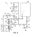
- FIG. 3 is a schematic diagram of the system of FIG. 1 illustrating a metered pulse injection operation.
- the term “decontaminant” includes, but is not limited to a chemical agent used as a sterilant, disinfectant, and the like.
- decontamination includes, but is not limited to, sterilization, disinfection and sanitation.
- FIG. 1 shows a system 10 for metering a liquid decontaminant into a vaporization system.
- vaporization system is a chamber 80.
- chamber 80 may be a decontamination chamber, a vaporization chamber, or the like.
- System 10 is generally comprised of a plurality of fluid conduits (described below) defming a plurality of fluid pathways, a decontaminant source 40, a reservoir 50, an injector 60, a vacuum source 100, and a plurality of valves (described below).
- Decontaminant source 40 provides a bulk supply of a liquid decontaminant (e.g., an aqueous solution of hydrogen peroxide).
- a liquid decontaminant e.g., an aqueous solution of hydrogen peroxide
- decontaminant source 40 may take the form of a vessel, a tank, a bottle, or other container suitable for storing liquid.
- Reservoir 50 has a first end 54 and a second end 56.
- Reservoir 50 may take the form of an enclosed container, such as a vessel, a tank or bottle.
- reservoir 50 is dimensioned to store a volume of liquid decontaminant sufficient for at least one complete decontamination cycle.
- a level sensor 58 is associated with reservoir 50 to sense the fluid level therein. Level sensor 58 may be located inside or outside reservoir 50.
- injector 60 is generally comprised of a cylinder 62, and a piston 68.
- Injector 60 has a first port at a first end 64 and a second port at a second end 66.
- cylinder 62 has a head section 61 for collecting liquid decontaminant and a spring section 63 that receives a spring 69.
- Spring 69 acts as a bias means to bias piston 68 toward the first port at first end 64.
- Injector 60 also includes a first limit switch 72 and a second limit switch 74. Limit switches 72 and 74 provide an indication of the position of pistion 68 within cylinder 62. In this regard, first limit switch 72 is activated when piston 68 is located at a first position inside cylinder 62.
- Second limit switch 74 is activated when piston 68 is located at a second position inside cylinder 62.
- head section 61 contains a predetermined volume of liquid decontaminant, as will be described in further detail below.
- injector 60 may have alternative forms, including, but not limited to, a syringe, a bladder, a chamber or a vessel. In a preferred embodiment, injector 60 is dimensioned to store a volume of liquid decontaminant for a single pulse of the decontamination cycle.
- vacuum source 100 is comprised of a pump 102 driven by a motor 104.
- Pump 102 is used to generate a vacuum, as will be described in detail below.
- pump 102 has the capacity to generate a vacuum in the range of about .0001 Torr to about 760 Torr.
- a control unit (not shown) is provided to control operation of vacuum source 100, actuate valves, and receive sensor data signals from level sensor 58 and switches 72 and 74.
- the control unit may include a microprocessor or microcontroller.
- First end 54 of reservoir 50 is fluidly connectable with decontaminant supply 40 and first end 64 of injector 60.
- Second end 56 of reservoir 50 is fluidly connectable with vacuum source 100.
- First end 64 of injector 60 is fluidly connectable with first end 54 of reservoir 50 and chamber 80.
- Second end 66 of injector 60 is fluidly connectable with vacuum source 100.
- Chamber 80 is fluidly connectable with first end 64 of injector 60 and vacuum source 100.
- a first conduit 12 is in fluid communication with decontaminant source 40 and first end 54 of reservoir 50.
- a first valve 30 is disposed in first conduit 12 between decontaminant source 40 and reservoir 50 to regulate fluid flow through first conduit 12.
- a filter 24 is also provided in first conduit 12 to filter the liquid decontaminant before it is received by reservoir 50.
- a second conduit 14 is in fluid communication with first end 54 of reservoir 50 and a fourth conduit 16, described below.
- a third conduit 15 is in fluid communication with second end 56 of reservoir 50 and a fifth conduit 18, described below.
- a second valve 32 is disposed in third conduit 15 between reservoir 50 and fifth conduit 18 to regulate fluid flow therethrough.
- Valve 32 is a three-way valve having first and second ports connected with third conduit 15, and a third port connected with a vent to atmospheric pressure. In the illustrated embodiment valve 32 has only two positions. In a first position, valve 32 puts second end of reservoir 56 in fluid communication with a vent to atmospheric pressure. In a second position, valve 32 puts second end of reservoir 50 in fluid communication with vacuum source 100.
- a restrictor valve 33 is disposed in third conduit 15 between second valve 32 and fifth conduit 18. Restrictor valve 33 provides a controlled fluid flow rate through conduit 15.
- Fourth conduit 16 is in fluid communication with first end 64 of injector 60, second conduit 14, and chamber 80.
- a third valve 34 is disposed in fourth conduit 16.
- Valve 34 is a three-way valve having first and second ports connected with fourth conduit 16 and a third port connected with second conduit 14. Accordingly, fluid flow through conduits 14 and 16 is regulated by valve 34.
- valve 34 has only two positions. In a first position (i.e., default position), valve 34 puts first end 54 of reservoir 50 in fluid communication with first end 64 of injector 60. In a second position, valve 34 puts chamber 80 in fluid communication with first end 64 of injector 60.
- Fifth conduit 18 is in fluid communication with second end 66 of injector 60, third conduit 15, and a sixth conduit 20, described below.
- a fourth valve 36 is disposed in fifth conduit 18.
- Valve 36 is a three-way valve having first and second ports connected with fifth conduit 18, and a third port connected with a vent to atmospheric pressure. In the illustrated embodiment, valve 36 has only two positions. In a first position (i.e., default position), valve 36 puts second end 66 of injector 60 in fluid communication with a vent to atmospheric pressure. In a second position, valve 36 puts second end 66 of injector 60 in fluid communication with vacuum source 100.
- Third conduit 15 is in fluid communication with fifth conduit 18 between valve 36 and sixth conduit 20.
- Sixth conduit 20 is in fluid communication with chamber 80, fifth conduit 18, and vacuum source 100.
- a fifth valve 38 is disposed in sixth conduit 20 to regulate fluid flow therethrough.
- Fifth conduit 18 is connected with sixth conduit 20 between valve 38 and vacuum source 100.
- valve 30 is actuated to move to a position wherein reservoir 50 is in fluid communication with decontaminant source 40; valve 32 is actuated to move to a position wherein reservoir 50 is in fluid communication with vacuum source 100; valve 34 is in a default position wherein reservoir 50 is in fluid communication with first end 64 of injector 60; valve 36 is in a default position wherein second end 66 of injector 60 is in fluid communication with a vent to atmospheric pressure; and valve 38 is in a position wherein there is no fluid communication between chamber 80 and vacuum source 100.
- vacuum source 100 is activated, a vacuum is created at second end 56 of reservoir 50.
- liquid decontaminant flows through conduit 12 from decontaminant source 40 into reservoir 50.
- Vacuum source 100 remains activated and valve 32 remains in a position wherein reservoir 50 is in fluid communication with vacuum source 100, until the amount of liquid decontaminant inside reservoir 50 reaches a predetermined limit sensed by level sensor 58.
- sensor 58 generates a signal, received by the control unit, indicating that the liquid decontaminant in reservoir 50 has reached a predetermined level.
- valve 30 is actuated to move to a position terminating fluid communication between reservoir 50 and decontaminant source 40.
- Vacuum source 100 continues to draw a vacuum at second end 56 of reservoir 50 for a predetermined time period to remove any entrained air inside reservoir 50, second conduit 14, and injector 60. Once the entrained air has been removed, valve 32 is actuated to move to a position terminating fluid communication between reservoir 50 and vacuum source 100, and putting second end 56 of reservoir 50 in fluid communication with a vent to atmospheric pressure.
- valve 38 is actuated to move to a position wherein chamber 80 is in fluid communication with vacuum source 100. After chamber 80 has been charged with a vacuum, valve 38 is actuated to move to a position wherein fluid communication between chamber 80 and vacuum source 100 is terminated.
- An injector fill operation commences after completion of the reservoir fill operation and charging of chamber 80, as described above.
- valve 36 is actuated to move to a position wherein second end 66 of injector 60 is in fluid communication with vacuum source 100.
- Valve 34 remains in a default position wherein first end 54 of reservoir 50 is in fluid communication with first end 64 of injector 60, and valve 32 remains in a position wherein second end 56 of reservoir 50 is in fluid communication with a vent to atmospheric pressure.
- piston 68 of injector 60 is initially located at a first position at first end 64 of injector 60 (as verified by activation of switch 72), when the injector fill operation commences.
- piston 68 moves against spring 69 to a second position at second end 66 of injector 60 (as verified by activation of switch 74), as shown in FIG. 2 .
- switch 74 As piston 68 moves between the first and second positions, liquid decontaminant is drawn from reservoir 50 into head section 61 of cylinder 62.
- head section 61 of cylinder 62 is dimensioned to receive a predetermined volume of liquid decontaminant, wherein the predetermined volume is a preferred volume of liquid decontaminant for a single pulse of a decontamination cycle.
- Valve 36 remains in a position wherein second end 66 of injector 60 is in fluid communication with vacuum source 100.
- valve 34 is actuated to move to a position wherein first end 64 of injector 60 is in fluid communication with chamber 80; and valve 36 is actuated to move to a position wherein second end 66 of injector 60 is in fluid communication with a vent to atmospheric pressure. Since chamber 80 has been previously charged with a vacuum (as described above), a vacuum is established at first end 64 of injector 60.
- Subsequent metered pulses of liquid decontaminant are injected into chamber 80 by repeating the foregoing injector fill and metered pulse injection operations.
Landscapes
- Health & Medical Sciences (AREA)
- Public Health (AREA)
- General Health & Medical Sciences (AREA)
- Veterinary Medicine (AREA)
- Epidemiology (AREA)
- Life Sciences & Earth Sciences (AREA)
- Animal Behavior & Ethology (AREA)
- Fluid Mechanics (AREA)
- Chemical & Material Sciences (AREA)
- General Chemical & Material Sciences (AREA)
- Chemical Kinetics & Catalysis (AREA)
- Physics & Mathematics (AREA)
- General Physics & Mathematics (AREA)
- Feeding, Discharge, Calcimining, Fusing, And Gas-Generation Devices (AREA)
- Apparatus For Disinfection Or Sterilisation (AREA)
- Consolidation Of Soil By Introduction Of Solidifying Substances Into Soil (AREA)
- Reciprocating Pumps (AREA)
- Measuring Volume Flow (AREA)
- Infusion, Injection, And Reservoir Apparatuses (AREA)
Abstract
Description
- The present invention relates generally to a method and apparatus for metering a liquid, and more particularly to a method and apparatus for metering a liquid decontaminant into a vaporization system, where the vaporized decontaminant produced by the vaporization system is typically used in a decontamination process.
- Generally, in a vapor phase decontamination process (e.g., deep vacuum sterilization), a liquid decontaminant is metered from a reservoir or other container into a vaporizer or decontamination chamber in which vaporization occurs. In this regard, a deep vacuum is drawn inside the chamber, and a metered amount of liquid decontaminant is then drawn into the chamber, where it vaporizes in the deep vacuum. To ensure effective and efficient decontamination, the liquid decontaminant should be metered in accurately and reproducibly measured amounts.
US 6,209,591 B1 discloses an apparatus and method for filling a container in an aseptic processing apparatus, wherein an applicator spray nozzle is used to inject a chemical sterilant into a bottle.US 2002/0157726 A1 discloses a method for delivering liquid with a container delivery system, wherein a metering tube and valves are used to control the flow of a liquid sterilant to a vaporizer. - Prior art approaches for metering a liquid decontaminant have been complex and costly due to the need for such components as an electronic balance, multiple pumps or external pressure sources for drawing vacuums at different locations within a system. Accordingly, there is a need for a simpler and less costly approach for delivering metered amounts of a liquid decontaminant to a vaporization chamber. The present invention addresses these and other deficiencies of the prior art.
- In accordance with the present invention, there is provided a system for metering a predetermind quantity of a liquid decontaminant into a chamber, the system comprising: a vacuum source; a source of the liquid decontaminant; a reservoir for storing the liquid decontaminant; and an injection means for injecting a predetermined quantity of liquid decontaminant into the chamber, wherein the reservoir is fluidly connectable with the source of the liquid decontaminant, the injection means, and the vacuum source; the injection means is fluidly connectable with the chamber and the vacuum source; and the chamber is fluidly connectable with the vacuum source; and the characterizing features of claim 1.
- In accordance with another aspect of the present invention, there is provided a method for metering a predetermined quantity of a liquid decontaminant into a chamber, the method comprising: transferring a liquid decontaminant from a source of liquid decontaminant to a reservoir by putting the reservoir in fluid communication with the source of liquid decontaminant and with a vacuum source; transferring the liquid decontaminant from the reservoir to an injection means by putting the reservoir in fluid communication with the injection means, and putting the injection means in fluid communication with the vacuum source; and metering liquid decontaminant from the injection means to the chamber by putting injection means in fluid communication with the chamber having a vacuum created therein; wherein the step of transferring liquid decontaminant from the reservoir to the injection means and the step of metering liquid decontaminant from the injection means to the chamber include the features according to claim 9.
- An advantage of the present invention is the provision of a method and apparatus for metering a liquid decontaminant that efficiently uses a single vacuum pump to draw fluids throughout a system.
- Another advantage of the present invention is the provision of a method and apparatus for metering a liquid decontaminant that is less costly than prior art approaches.
- Still another advantage of the present invention is the provision of a method and apparatus for metering a liquid decontaminant that is less complex than prior art approaches.
- Still another advantage of the present invention is the provision of a method and apparatus for metering a liquid decontaminant that provides improved accuracy and consistency by removing air bubbles from the system prior to filling an injector with a metered quantity of liquid decontaminant.
- These and other advantages will become apparent from the following description of a preferred embodiment taken together with the accompanying drawings and the appended claims.
- The invention may take physical form in certain parts and arrangement of parts, a preferred embodiment of which will be described in detail in the specification and illustrated in the accompanying drawings which form a part hereof, and wherein:
-
FIG. 1 is a schematic diagram of a system for metering a liquid decontaminant into a vaporization system, according to a preferred embodiment of the present invention, whereinFIG. 1 illustrates a reservoir fill operation; -
FIG. 2 is a schematic diagram of the system ofFIG. 1 illustrating an injector fill operation; and -
FIG. 3 is a schematic diagram of the system ofFIG. 1 illustrating a metered pulse injection operation. - As used herein, the term "decontaminant" includes, but is not limited to a chemical agent used as a sterilant, disinfectant, and the like. The term "decontamination" includes, but is not limited to, sterilization, disinfection and sanitation.
- Referring now to the drawings wherein the showings are for the purposes of illustrating a preferred embodiment of the invention only and not for the purposes of limiting same,
FIG. 1 shows asystem 10 for metering a liquid decontaminant into a vaporization system. In the illustrated embodiment, vaporization system is achamber 80. It should be appreciated thatchamber 80 may be a decontamination chamber, a vaporization chamber, or the like. -
System 10 is generally comprised of a plurality of fluid conduits (described below) defming a plurality of fluid pathways, adecontaminant source 40, areservoir 50, aninjector 60, avacuum source 100, and a plurality of valves (described below). -
Decontaminant source 40 provides a bulk supply of a liquid decontaminant (e.g., an aqueous solution of hydrogen peroxide). By way of example, and not limitation,decontaminant source 40 may take the form of a vessel, a tank, a bottle, or other container suitable for storing liquid. -
Reservoir 50 has afirst end 54 and asecond end 56.Reservoir 50 may take the form of an enclosed container, such as a vessel, a tank or bottle. In a preferred embodiment,reservoir 50 is dimensioned to store a volume of liquid decontaminant sufficient for at least one complete decontamination cycle. Alevel sensor 58 is associated withreservoir 50 to sense the fluid level therein.Level sensor 58 may be located inside oroutside reservoir 50. - In the illustrated embodiment,
injector 60 is generally comprised of acylinder 62, and apiston 68.Injector 60 has a first port at afirst end 64 and a second port at asecond end 66. In the illustrated embodiment,cylinder 62 has ahead section 61 for collecting liquid decontaminant and aspring section 63 that receives aspring 69.Spring 69 acts as a bias means to biaspiston 68 toward the first port atfirst end 64.Injector 60 also includes afirst limit switch 72 and asecond limit switch 74.Limit switches pistion 68 withincylinder 62. In this regard,first limit switch 72 is activated whenpiston 68 is located at a first position insidecylinder 62.Second limit switch 74 is activated whenpiston 68 is located at a second position insidecylinder 62. Whenpiston 68 is located at the second position insidecylinder 62,head section 61 contains a predetermined volume of liquid decontaminant, as will be described in further detail below. It should be appreciated thatinjector 60 may have alternative forms, including, but not limited to, a syringe, a bladder, a chamber or a vessel. In a preferred embodiment,injector 60 is dimensioned to store a volume of liquid decontaminant for a single pulse of the decontamination cycle. - According to an illustrated embodiment of the present invention,
vacuum source 100 is comprised of apump 102 driven by amotor 104.Pump 102 is used to generate a vacuum, as will be described in detail below. In a preferred embodiment,pump 102 has the capacity to generate a vacuum in the range of about .0001 Torr to about 760 Torr. - A control unit (not shown) is provided to control operation of
vacuum source 100, actuate valves, and receive sensor data signals fromlevel sensor 58 andswitches -
First end 54 ofreservoir 50 is fluidly connectable withdecontaminant supply 40 andfirst end 64 ofinjector 60.Second end 56 ofreservoir 50 is fluidly connectable withvacuum source 100.First end 64 ofinjector 60 is fluidly connectable withfirst end 54 ofreservoir 50 andchamber 80.Second end 66 ofinjector 60 is fluidly connectable withvacuum source 100.Chamber 80 is fluidly connectable withfirst end 64 ofinjector 60 andvacuum source 100. - The fluid conduits connecting with
decontaminant source 40,reservoir 50,injector 60,chamber 80 andvacuum source 100 will now be described with reference to the illustrated embodiment. The arrangement of fluid conduits of the illustrated embodiment is exemplary, and is not intended to limit the scope of the present invention. It should be appreciated that the present invention can be practiced using alternative arrangements of the fluid conduits. - A
first conduit 12 is in fluid communication withdecontaminant source 40 andfirst end 54 ofreservoir 50. Afirst valve 30 is disposed infirst conduit 12 betweendecontaminant source 40 andreservoir 50 to regulate fluid flow throughfirst conduit 12. In the illustrated embodiment, afilter 24 is also provided infirst conduit 12 to filter the liquid decontaminant before it is received byreservoir 50. - A
second conduit 14 is in fluid communication withfirst end 54 ofreservoir 50 and afourth conduit 16, described below. - A
third conduit 15 is in fluid communication withsecond end 56 ofreservoir 50 and afifth conduit 18, described below. Asecond valve 32 is disposed inthird conduit 15 betweenreservoir 50 andfifth conduit 18 to regulate fluid flow therethrough.Valve 32 is a three-way valve having first and second ports connected withthird conduit 15, and a third port connected with a vent to atmospheric pressure. In the illustratedembodiment valve 32 has only two positions. In a first position,valve 32 puts second end ofreservoir 56 in fluid communication with a vent to atmospheric pressure. In a second position,valve 32 puts second end ofreservoir 50 in fluid communication withvacuum source 100. In the illustrated embodiment, arestrictor valve 33 is disposed inthird conduit 15 betweensecond valve 32 andfifth conduit 18.Restrictor valve 33 provides a controlled fluid flow rate throughconduit 15. -
Fourth conduit 16 is in fluid communication withfirst end 64 ofinjector 60,second conduit 14, andchamber 80. Athird valve 34 is disposed infourth conduit 16.Valve 34 is a three-way valve having first and second ports connected withfourth conduit 16 and a third port connected withsecond conduit 14. Accordingly, fluid flow throughconduits valve 34. In the illustrated embodiment,valve 34 has only two positions. In a first position (i.e., default position),valve 34 putsfirst end 54 ofreservoir 50 in fluid communication withfirst end 64 ofinjector 60. In a second position,valve 34 putschamber 80 in fluid communication withfirst end 64 ofinjector 60. -
Fifth conduit 18 is in fluid communication withsecond end 66 ofinjector 60,third conduit 15, and asixth conduit 20, described below. Afourth valve 36 is disposed infifth conduit 18.Valve 36 is a three-way valve having first and second ports connected withfifth conduit 18, and a third port connected with a vent to atmospheric pressure. In the illustrated embodiment,valve 36 has only two positions. In a first position (i.e., default position),valve 36 putssecond end 66 ofinjector 60 in fluid communication with a vent to atmospheric pressure. In a second position,valve 36 putssecond end 66 ofinjector 60 in fluid communication withvacuum source 100.Third conduit 15 is in fluid communication withfifth conduit 18 betweenvalve 36 andsixth conduit 20. -
Sixth conduit 20 is in fluid communication withchamber 80,fifth conduit 18, andvacuum source 100. Afifth valve 38 is disposed insixth conduit 20 to regulate fluid flow therethrough.Fifth conduit 18 is connected withsixth conduit 20 betweenvalve 38 andvacuum source 100. - Operation of
metering system 10 will now be described. Referring first toFIG. 1 , there is shown a reservoir fill operation.Valve 30 is actuated to move to a position whereinreservoir 50 is in fluid communication withdecontaminant source 40;valve 32 is actuated to move to a position whereinreservoir 50 is in fluid communication withvacuum source 100;valve 34 is in a default position whereinreservoir 50 is in fluid communication withfirst end 64 ofinjector 60;valve 36 is in a default position whereinsecond end 66 ofinjector 60 is in fluid communication with a vent to atmospheric pressure; andvalve 38 is in a position wherein there is no fluid communication betweenchamber 80 andvacuum source 100. Whenvacuum source 100 is activated, a vacuum is created atsecond end 56 ofreservoir 50. As a result, liquid decontaminant flows throughconduit 12 fromdecontaminant source 40 intoreservoir 50. Vacuumsource 100 remains activated andvalve 32 remains in a position whereinreservoir 50 is in fluid communication withvacuum source 100, until the amount of liquid decontaminant insidereservoir 50 reaches a predetermined limit sensed bylevel sensor 58. In this regard,sensor 58 generates a signal, received by the control unit, indicating that the liquid decontaminant inreservoir 50 has reached a predetermined level. In response to the signal generated bysensor 58,valve 30 is actuated to move to a position terminating fluid communication betweenreservoir 50 anddecontaminant source 40. Vacuumsource 100 continues to draw a vacuum atsecond end 56 ofreservoir 50 for a predetermined time period to remove any entrained air insidereservoir 50,second conduit 14, andinjector 60. Once the entrained air has been removed,valve 32 is actuated to move to a position terminating fluid communication betweenreservoir 50 andvacuum source 100, and puttingsecond end 56 ofreservoir 50 in fluid communication with a vent to atmospheric pressure. - Before commencing a metered pulse injection operation (described below)
chamber 80 is charged with a vacuum.Valve 38 is actuated to move to a position whereinchamber 80 is in fluid communication withvacuum source 100. Afterchamber 80 has been charged with a vacuum,valve 38 is actuated to move to a position wherein fluid communication betweenchamber 80 andvacuum source 100 is terminated. - An injector fill operation (see
FIG. 2 ) commences after completion of the reservoir fill operation and charging ofchamber 80, as described above. To begin the injector fill operation,valve 36 is actuated to move to a position whereinsecond end 66 ofinjector 60 is in fluid communication withvacuum source 100.Valve 34 remains in a default position whereinfirst end 54 ofreservoir 50 is in fluid communication withfirst end 64 ofinjector 60, andvalve 32 remains in a position whereinsecond end 56 ofreservoir 50 is in fluid communication with a vent to atmospheric pressure. - In the illustrated embodiment,
piston 68 ofinjector 60 is initially located at a first position atfirst end 64 of injector 60 (as verified by activation of switch 72), when the injector fill operation commences. As a vacuum is established atsecond end 66 ofinjector 60,piston 68 moves againstspring 69 to a second position atsecond end 66 of injector 60 (as verified by activation of switch 74), as shown inFIG. 2 . Aspiston 68 moves between the first and second positions, liquid decontaminant is drawn fromreservoir 50 intohead section 61 ofcylinder 62. In a preferred embodiment,head section 61 ofcylinder 62 is dimensioned to receive a predetermined volume of liquid decontaminant, wherein the predetermined volume is a preferred volume of liquid decontaminant for a single pulse of a decontamination cycle.Valve 36 remains in a position whereinsecond end 66 ofinjector 60 is in fluid communication withvacuum source 100. - Referring now to
FIG. 3 , there is shown a metered pulse injection operation. At the appropriate time for injecting a metered pulse of liquid decontaminant intochamber 80,valve 34 is actuated to move to a position whereinfirst end 64 ofinjector 60 is in fluid communication withchamber 80; andvalve 36 is actuated to move to a position whereinsecond end 66 ofinjector 60 is in fluid communication with a vent to atmospheric pressure. Sincechamber 80 has been previously charged with a vacuum (as described above), a vacuum is established atfirst end 64 ofinjector 60. As a result,spring 69 expands to movepiston 68 from the second position atsecond end 66 of injector 60 (as verified by activation of second switch 74) to the first position atfirst end 64 of injector 60 (as verified by activation of first switch 72). As a result, liquid decontaminant fromhead section 61 ofcylinder 62 flows frominjector 60 intochamber 80. The liquid decontaminant injected intochamber 80 is vaporized therein. After a metered pulse of liquid decontaminant has been injected intochamber 80,valve 34 is actuated to move to the default position, thus terminating fluid communication betweenfirst end 64 ofinjector 60 andchamber 80. - Subsequent metered pulses of liquid decontaminant are injected into
chamber 80 by repeating the foregoing injector fill and metered pulse injection operations.
Claims (15)
- A system for metering a predetermined quantity of a liquid decontaminant into a chamber (80), the system comprising:a vacuum source (100);a source (40) of the liquid decontaminant;a reservoir (50) for storing the liquid decontaminant; andan injection means (60) for injecting a predetermined quantity of liquid decontaminant into the chamber (80),wherein the reservoir (50) is fluidly connected with the source (40) of the liquid decontaminant, the injection means (60), and the vacuum source (100), the injection means (60) is fluidly connected with the chamber (80) and the vacuum source (100), and the chamber (80) is fluidly connected with the vacuum source (100), characterized in thatsaid injection means (60) includes a piston (68), movable between a first position and a second position, and a cylinder (62), wherein liquid decontaminant is introduced into the cylinder (62) by movement of the piston (68) from the first position to the second position, and liquid decontaminant is introduced into the chamber (80) by movement of the piston (68) from the second position to the first position.
- A system according to claim 1, wherein said system further comprises:a first valve (30) for controlling fluid flow between said source (40) of liquid decontaminant and said reservoir (50);a second valve (32) for controlling fluid flow between said reservoir (50) and said vacuum source (100);a third valve (34) for controlling fluid flow between said reservoir (50) and said injection means (60) and for controlling fluid flow between said injection means (60) and said chamber (80);a fourth valve (36) for controlling fluid flow between said injection means (60) and said vacuum source (100); anda fifth valve (38) for controlling fluid flow between said chamber (80) and said vacuum source (100).
- A system according to claim 2, wherein said second valve (32) is movable to a position wherein said reservoir (50) is in fluid communication with atmospheric pressure.
- A system according to claim 2, wherein said fourth valve (36) is movable to a position wherein said injection means (60) is in fluid communication with atmospheric pressure.
- A system according to claim 1, wherein said system further comprises:sensing means (58) for sensing the level of liquid decontaminant in said reservoir (50), wherein the sensing means (58) generates a signal indicating that the liquid decontaminant in said reservoir (50) has reached a predetermined level.
- A system according to claim 1, wherein said injection (60) means is dimensioned to receive a predetermined volume of liquid decontaminant from said reservoir (50).
- A system according to claim 1, wherein said vacuum source (100) includes a pump (102).
- A system according to claim 1, wherein said liquid decontaminant includes hydrogen peroxide.
- A method for metering a predetermined quantity of a liquid decontaminant into a chamber (80), the method comprising:transferring a liquid decontaminant from a source (40) of liquid decontaminant to a reservoir (50) by putting the reservoir (50) in fluid communication with the source (40) of liquid decontaminant and with a vacuum source (100);transferring the liquid decontaminant from the reservoir (50) to an injection means (60) by putting the reservoir (50) in fluid communication with the injection means (60), and putting the injection means (60) in fluid communication with the vacuum source (100); andmetering liquid decontaminant from the injection means (100) to the chamber (80) by putting injection means (60) in fluid communication with the chamber (80) having a vacuum created therein,wherein the step of transferring liquid decontaminant from the reservoir (50) to the injection means (60) includes moving a piston (68) from a first position to a second position to introduce the liquid decontaminant into the injection means (60), andwherein the step of metering liquid decontaminant from the injection means (60) to the chamber (80) includes moving the piston (68) from the second position to the first position to introduce the liquid decontaminant into the chamber (80).
- A method according to claim 9, wherein a vacuum is created in said chamber (80) by putting the chamber (80) in fluid communication with said vacuum source (100).
- A method according to claim 9, wherein said reservoir (50) is also in fluid communication with atmospheric pressure when transferring the liquid decontaminant from the reservoir (50) to the injection means (60).
- A method according to claim 9, wherein said injection means (60) is also in fluid communication with atmospheric pressure when metering liquid decontaminant from the injection means (60) to the chamber (80).
- A method according to claim 9, wherein said method further comprises:sensing the level of the liquid decontaminant in said reservoir (50) as liquid decontaminant is transferred from said source (40) of liquid decontaminant to said reservoir (50); andgenerating a signal indicating that the liquid decontaminant in said reservoir (50) has reached a predetermined level.
- A method according to claim 9, wherein said injection means (60) is dimensioned to receive a predetermined volume of liquid decontaminant from said reservoir (50).
- A method according to claim 9, wherein said liquid decontaminant includes hydrogen peroxide.
Applications Claiming Priority (2)
| Application Number | Priority Date | Filing Date | Title |
|---|---|---|---|
| US11/186,536 US7429353B2 (en) | 2005-07-21 | 2005-07-21 | Method and apparatus for injecting a metered quantity of a liquid into a chamber |
| PCT/US2006/023370 WO2007018742A2 (en) | 2005-07-21 | 2006-06-16 | Method and apparatus for injecting a metered quantity of a liquid into a chamber |
Publications (3)
| Publication Number | Publication Date |
|---|---|
| EP1904115A2 EP1904115A2 (en) | 2008-04-02 |
| EP1904115A4 EP1904115A4 (en) | 2008-10-29 |
| EP1904115B1 true EP1904115B1 (en) | 2010-09-01 |
Family
ID=37679234
Family Applications (1)
| Application Number | Title | Priority Date | Filing Date |
|---|---|---|---|
| EP06784944A Active EP1904115B1 (en) | 2005-07-21 | 2006-06-16 | Method and apparatus for injecting a metered quantity of a liquid into a chamber |
Country Status (13)
| Country | Link |
|---|---|
| US (1) | US7429353B2 (en) |
| EP (1) | EP1904115B1 (en) |
| JP (1) | JP5355083B2 (en) |
| KR (1) | KR20080036582A (en) |
| CN (1) | CN101321543B (en) |
| AT (1) | ATE479445T1 (en) |
| AU (1) | AU2006276894B2 (en) |
| CA (1) | CA2615446C (en) |
| DE (1) | DE602006016606D1 (en) |
| ES (1) | ES2351355T3 (en) |
| MX (1) | MX2008000740A (en) |
| TW (1) | TWI294288B (en) |
| WO (1) | WO2007018742A2 (en) |
Families Citing this family (11)
| Publication number | Priority date | Publication date | Assignee | Title |
|---|---|---|---|---|
| US20070098591A1 (en) * | 2005-10-31 | 2007-05-03 | Georg Frinke | Method and apparatus for low energy vaporization of liquid oxidizing agents or solutions |
| KR100845533B1 (en) | 2007-02-23 | 2008-07-10 | 주식회사 휴먼메디텍 | Liquid dosing device of plasma sterilization system |
| TR201900045T4 (en) | 2009-09-30 | 2019-01-21 | Tso3 Inc | STERILIZATION METHOD. |
| KR101049571B1 (en) * | 2009-11-02 | 2011-07-15 | 주식회사 델타메디칼 | Plasma sterilizer |
| JP4674272B1 (en) | 2010-11-24 | 2011-04-20 | オリンパスメディカルシステムズ株式会社 | Endoscope cleaning disinfection device |
| US9173968B2 (en) | 2011-10-06 | 2015-11-03 | Canon Marketing Japan Kabushiki Kaisha | Sterilization apparatus and sterilization method |
| JP5668666B2 (en) * | 2011-10-31 | 2015-02-12 | キヤノンマーケティングジャパン株式会社 | Sterilizer, sterilization method |
| JP5545283B2 (en) * | 2011-10-06 | 2014-07-09 | キヤノンマーケティングジャパン株式会社 | Sterilizer, sterilization method |
| JP5783296B2 (en) * | 2014-05-13 | 2015-09-24 | キヤノンマーケティングジャパン株式会社 | Sterilizer, sterilization method |
| JP6322050B2 (en) * | 2014-05-20 | 2018-05-09 | 株式会社フジキン | Fluid concentration vaporizer |
| CN104891410B (en) * | 2015-04-28 | 2017-03-08 | 北京航空航天大学 | A vehicle-mounted hydrogen peroxide filling system |
Family Cites Families (28)
| Publication number | Priority date | Publication date | Assignee | Title |
|---|---|---|---|---|
| US4169123A (en) | 1975-12-11 | 1979-09-25 | Moore-Perk Corporation | Hydrogen peroxide vapor sterilization method |
| US4169124A (en) | 1977-09-26 | 1979-09-25 | Moore-Perk Corporation | Cold gas sterilization process |
| DE2757897C3 (en) * | 1977-12-24 | 1980-07-03 | Jagenberg-Werke Ag, 4000 Duesseldorf | Device for the pulsed delivery of very small amounts of liquid, in particular H2 O2 |
| JPS55110553A (en) * | 1979-02-15 | 1980-08-26 | American Sterilizer Co | Steam sterilizing method and its device |
| US4230663A (en) | 1979-07-10 | 1980-10-28 | Moore-Perk Corporation | Cold gas sterilization process using hydrogen peroxide at low concentrations |
| US4512951A (en) | 1980-12-30 | 1985-04-23 | American Sterilizer Company | Hydrogen peroxide liquid film sterilization method |
| GB8427999D0 (en) | 1983-11-07 | 1984-12-12 | American Sterilizer Co | Vaporization method |
| US4642165A (en) | 1984-12-21 | 1987-02-10 | American Sterilizer Company | Method of vaporizing multicomponent liquids |
| US4909999A (en) | 1987-07-06 | 1990-03-20 | American Sterilizer Company | Flow-through vapor phase sterilization system |
| DE3819419A1 (en) * | 1988-06-07 | 1989-12-14 | Jagenberg Ag | MEASURING DEVICE FOR DOSING DEVICES, ESPECIALLY FOR THE STERILIZATION OF PACKAGING MATERIAL OR - CONTAINERS |
| US5122344A (en) | 1990-01-31 | 1992-06-16 | Mdt Corporation | Chemical sterilizer system |
| US5244629A (en) | 1990-08-31 | 1993-09-14 | Caputo Ross A | Plasma sterilizing process with pulsed antimicrobial agent pretreatment |
| WO1993017726A1 (en) | 1992-03-13 | 1993-09-16 | American Sterilizer Company | Sterilization apparatus and method for multicomponent sterilant |
| US5445792A (en) | 1992-03-13 | 1995-08-29 | American Sterilizer Company | Optimum hydrogen peroxide vapor sterlization method |
| JP3549883B2 (en) | 1992-10-01 | 2004-08-04 | アメリカン ステリライザー カンパニー | Liquid dispensing system and dispensing method based on accumulator |
| CA2173161A1 (en) * | 1993-09-30 | 1995-04-06 | Kevin H. Butler | Method for dispensing liquid from a multi-dose cartridge |
| US5788925A (en) | 1996-02-16 | 1998-08-04 | Steris Corporation | Method for real time monitoring and control of load sterilization and parametric release |
| US5759486A (en) | 1996-03-27 | 1998-06-02 | Bill F. McGraw, Trustee | Apparatus and method for sterilization of instruments |
| US6325972B1 (en) | 1998-12-30 | 2001-12-04 | Ethicon, Inc. | Apparatus and process for concentrating a liquid sterilant and sterilizing articles therewith |
| WO1998018620A1 (en) * | 1996-10-29 | 1998-05-07 | Cryovac , Inc. | Rf-sealable pillow pouch |
| JP2000126582A (en) * | 1998-10-27 | 2000-05-09 | Yuuki Shokai:Kk | Functional water supply device |
| US6209591B1 (en) | 1999-02-02 | 2001-04-03 | Steuben Foods, Inc. | Apparatus and method for providing container filling in an aseptic processing apparatus |
| US6279622B1 (en) * | 2000-02-07 | 2001-08-28 | Ethicon, Inc. | Method and system for delivering and metering liquid sterilant |
| GB2360505A (en) * | 2000-03-21 | 2001-09-26 | Microflow Ltd | Continuous metered liquid flow system |
| US6699434B1 (en) | 2000-09-08 | 2004-03-02 | Ethicon, Inc. | Metering valve to deliver liquid |
| US6752959B2 (en) | 2001-10-05 | 2004-06-22 | Pepsico, Inc. | High-speed, low temperature sterilization and sanitization apparatus and method |
| JP2003153988A (en) * | 2001-11-22 | 2003-05-27 | Hiruson Dekku Kk | Alcohol steam sterilizer |
| JP4107211B2 (en) * | 2003-09-30 | 2008-06-25 | 澁谷工業株式会社 | Sterilizer supply device |
-
2005
- 2005-07-21 US US11/186,536 patent/US7429353B2/en active Active
-
2006
- 2006-06-05 TW TW095119924A patent/TWI294288B/en active
- 2006-06-16 JP JP2008522786A patent/JP5355083B2/en active Active
- 2006-06-16 DE DE602006016606T patent/DE602006016606D1/en active Active
- 2006-06-16 EP EP06784944A patent/EP1904115B1/en active Active
- 2006-06-16 CN CN200680026515.2A patent/CN101321543B/en active Active
- 2006-06-16 ES ES06784944T patent/ES2351355T3/en active Active
- 2006-06-16 AU AU2006276894A patent/AU2006276894B2/en active Active
- 2006-06-16 WO PCT/US2006/023370 patent/WO2007018742A2/en not_active Ceased
- 2006-06-16 MX MX2008000740A patent/MX2008000740A/en active IP Right Grant
- 2006-06-16 AT AT06784944T patent/ATE479445T1/en not_active IP Right Cessation
- 2006-06-16 KR KR1020087001414A patent/KR20080036582A/en not_active Ceased
- 2006-06-16 CA CA2615446A patent/CA2615446C/en active Active
Also Published As
| Publication number | Publication date |
|---|---|
| ES2351355T3 (en) | 2011-02-03 |
| EP1904115A2 (en) | 2008-04-02 |
| CA2615446C (en) | 2011-05-03 |
| MX2008000740A (en) | 2008-04-29 |
| TW200704411A (en) | 2007-02-01 |
| US20070020141A1 (en) | 2007-01-25 |
| CA2615446A1 (en) | 2007-02-15 |
| US7429353B2 (en) | 2008-09-30 |
| AU2006276894B2 (en) | 2010-03-04 |
| JP5355083B2 (en) | 2013-11-27 |
| DE602006016606D1 (en) | 2010-10-14 |
| EP1904115A4 (en) | 2008-10-29 |
| WO2007018742A2 (en) | 2007-02-15 |
| CN101321543A (en) | 2008-12-10 |
| CN101321543B (en) | 2015-03-25 |
| ATE479445T1 (en) | 2010-09-15 |
| JP2009501631A (en) | 2009-01-22 |
| TWI294288B (en) | 2008-03-11 |
| AU2006276894A1 (en) | 2007-02-15 |
| WO2007018742A3 (en) | 2008-05-02 |
| KR20080036582A (en) | 2008-04-28 |
Similar Documents
| Publication | Publication Date | Title |
|---|---|---|
| US7429353B2 (en) | Method and apparatus for injecting a metered quantity of a liquid into a chamber | |
| JP7035003B2 (en) | Tree injection system and method | |
| RU2633070C2 (en) | Tool re-processor and methods of re-processing devices | |
| JP2004066236A (en) | Accumulator-based liquid metering system and method | |
| RU2014147366A (en) | INTRODUCTION OF MEDICINES WITH MEASUREMENT OF PRESSURE AND INTERRUPTED FLOW FOR IDENTIFICATION OF THE FILLED-IN FLUID ANATOMIC SPACE ENVIRONMENT AND FOR PROVIDING IN THEIR INJECTION | |
| WO2020212612A1 (en) | Delivery devices, systems and methods of use | |
| WO2001003757A3 (en) | Medical fluid delivery system | |
| EP1121942A3 (en) | Method and system for delivering and metering liquid sterilant | |
| FR2848859B1 (en) | DISPENSING DEVICE FOR A NETWORK FOR DELIVERING MEDICAL FLUIDS TO A PATIENT | |
| US4139008A (en) | Controlled-dose injection apparatus | |
| KR20160063692A (en) | Apparatus for Filling Filler Fluid into Syringes and Method Therewith | |
| CN204050402U (en) | A kind of stratified soil disinfector | |
| WO2021092284A1 (en) | Differential pressure fluid delivery system | |
| JP2012196635A (en) | Liquid chemical injection apparatus and water supply unit | |
| US20230109668A9 (en) | Differential Pressure Fluid Delivery System | |
| KR101675059B1 (en) | apparatus for supplying fixed amount of sterilant of sterilant device | |
| HK1139457A1 (en) | Metering device for an infusion system |
Legal Events
| Date | Code | Title | Description |
|---|---|---|---|
| PUAI | Public reference made under article 153(3) epc to a published international application that has entered the european phase |
Free format text: ORIGINAL CODE: 0009012 |
|
| 17P | Request for examination filed |
Effective date: 20080109 |
|
| AK | Designated contracting states |
Kind code of ref document: A2 Designated state(s): AT BE BG CH CY CZ DE DK EE ES FI FR GB GR HU IE IS IT LI LT LU LV MC NL PL PT RO SE SI SK TR |
|
| AX | Request for extension of the european patent |
Extension state: AL BA HR MK YU |
|
| RAX | Requested extension states of the european patent have changed |
Extension state: RS Extension state: MK Extension state: HR Extension state: BA Extension state: AL |
|
| R17D | Deferred search report published (corrected) |
Effective date: 20080502 |
|
| RIC1 | Information provided on ipc code assigned before grant |
Ipc: A61L 2/20 20060101AFI20080514BHEP Ipc: A61L 2/18 20060101ALI20080514BHEP |
|
| REG | Reference to a national code |
Ref country code: HK Ref legal event code: DE Ref document number: 1114031 Country of ref document: HK |
|
| A4 | Supplementary search report drawn up and despatched |
Effective date: 20080930 |
|
| RIC1 | Information provided on ipc code assigned before grant |
Ipc: A61L 101/22 20060101ALN20080923BHEP Ipc: A61L 2/20 20060101AFI20080514BHEP Ipc: A61L 2/18 20060101ALI20080923BHEP Ipc: A61L 2/26 20060101ALI20080923BHEP |
|
| 17Q | First examination report despatched |
Effective date: 20081215 |
|
| GRAP | Despatch of communication of intention to grant a patent |
Free format text: ORIGINAL CODE: EPIDOSNIGR1 |
|
| GRAS | Grant fee paid |
Free format text: ORIGINAL CODE: EPIDOSNIGR3 |
|
| GRAA | (expected) grant |
Free format text: ORIGINAL CODE: 0009210 |
|
| DAX | Request for extension of the european patent (deleted) | ||
| AK | Designated contracting states |
Kind code of ref document: B1 Designated state(s): AT BE BG CH CY CZ DE DK EE ES FI FR GB GR HU IE IS IT LI LT LU LV MC NL PL PT RO SE SI SK TR |
|
| REG | Reference to a national code |
Ref country code: GB Ref legal event code: FG4D |
|
| REG | Reference to a national code |
Ref country code: CH Ref legal event code: EP |
|
| REG | Reference to a national code |
Ref country code: IE Ref legal event code: FG4D |
|
| REF | Corresponds to: |
Ref document number: 602006016606 Country of ref document: DE Date of ref document: 20101014 Kind code of ref document: P |
|
| REG | Reference to a national code |
Ref country code: NL Ref legal event code: VDEP Effective date: 20100901 |
|
| PG25 | Lapsed in a contracting state [announced via postgrant information from national office to epo] |
Ref country code: FI Free format text: LAPSE BECAUSE OF FAILURE TO SUBMIT A TRANSLATION OF THE DESCRIPTION OR TO PAY THE FEE WITHIN THE PRESCRIBED TIME-LIMIT Effective date: 20100901 Ref country code: LT Free format text: LAPSE BECAUSE OF FAILURE TO SUBMIT A TRANSLATION OF THE DESCRIPTION OR TO PAY THE FEE WITHIN THE PRESCRIBED TIME-LIMIT Effective date: 20100901 Ref country code: AT Free format text: LAPSE BECAUSE OF FAILURE TO SUBMIT A TRANSLATION OF THE DESCRIPTION OR TO PAY THE FEE WITHIN THE PRESCRIBED TIME-LIMIT Effective date: 20100901 |
|
| REG | Reference to a national code |
Ref country code: ES Ref legal event code: FG2A Effective date: 20110124 |
|
| LTIE | Lt: invalidation of european patent or patent extension |
Effective date: 20100901 |
|
| PG25 | Lapsed in a contracting state [announced via postgrant information from national office to epo] |
Ref country code: CY Free format text: LAPSE BECAUSE OF FAILURE TO SUBMIT A TRANSLATION OF THE DESCRIPTION OR TO PAY THE FEE WITHIN THE PRESCRIBED TIME-LIMIT Effective date: 20100901 Ref country code: PL Free format text: LAPSE BECAUSE OF FAILURE TO SUBMIT A TRANSLATION OF THE DESCRIPTION OR TO PAY THE FEE WITHIN THE PRESCRIBED TIME-LIMIT Effective date: 20100901 Ref country code: SI Free format text: LAPSE BECAUSE OF FAILURE TO SUBMIT A TRANSLATION OF THE DESCRIPTION OR TO PAY THE FEE WITHIN THE PRESCRIBED TIME-LIMIT Effective date: 20100901 |
|
| PG25 | Lapsed in a contracting state [announced via postgrant information from national office to epo] |
Ref country code: GR Free format text: LAPSE BECAUSE OF FAILURE TO SUBMIT A TRANSLATION OF THE DESCRIPTION OR TO PAY THE FEE WITHIN THE PRESCRIBED TIME-LIMIT Effective date: 20101202 Ref country code: LV Free format text: LAPSE BECAUSE OF FAILURE TO SUBMIT A TRANSLATION OF THE DESCRIPTION OR TO PAY THE FEE WITHIN THE PRESCRIBED TIME-LIMIT Effective date: 20100901 Ref country code: NL Free format text: LAPSE BECAUSE OF FAILURE TO SUBMIT A TRANSLATION OF THE DESCRIPTION OR TO PAY THE FEE WITHIN THE PRESCRIBED TIME-LIMIT Effective date: 20100901 Ref country code: SE Free format text: LAPSE BECAUSE OF FAILURE TO SUBMIT A TRANSLATION OF THE DESCRIPTION OR TO PAY THE FEE WITHIN THE PRESCRIBED TIME-LIMIT Effective date: 20100901 |
|
| PG25 | Lapsed in a contracting state [announced via postgrant information from national office to epo] |
Ref country code: EE Free format text: LAPSE BECAUSE OF FAILURE TO SUBMIT A TRANSLATION OF THE DESCRIPTION OR TO PAY THE FEE WITHIN THE PRESCRIBED TIME-LIMIT Effective date: 20100901 Ref country code: IS Free format text: LAPSE BECAUSE OF FAILURE TO SUBMIT A TRANSLATION OF THE DESCRIPTION OR TO PAY THE FEE WITHIN THE PRESCRIBED TIME-LIMIT Effective date: 20110101 Ref country code: PT Free format text: LAPSE BECAUSE OF FAILURE TO SUBMIT A TRANSLATION OF THE DESCRIPTION OR TO PAY THE FEE WITHIN THE PRESCRIBED TIME-LIMIT Effective date: 20110103 Ref country code: CZ Free format text: LAPSE BECAUSE OF FAILURE TO SUBMIT A TRANSLATION OF THE DESCRIPTION OR TO PAY THE FEE WITHIN THE PRESCRIBED TIME-LIMIT Effective date: 20100901 Ref country code: SK Free format text: LAPSE BECAUSE OF FAILURE TO SUBMIT A TRANSLATION OF THE DESCRIPTION OR TO PAY THE FEE WITHIN THE PRESCRIBED TIME-LIMIT Effective date: 20100901 Ref country code: RO Free format text: LAPSE BECAUSE OF FAILURE TO SUBMIT A TRANSLATION OF THE DESCRIPTION OR TO PAY THE FEE WITHIN THE PRESCRIBED TIME-LIMIT Effective date: 20100901 |
|
| PG25 | Lapsed in a contracting state [announced via postgrant information from national office to epo] |
Ref country code: BE Free format text: LAPSE BECAUSE OF FAILURE TO SUBMIT A TRANSLATION OF THE DESCRIPTION OR TO PAY THE FEE WITHIN THE PRESCRIBED TIME-LIMIT Effective date: 20100901 |
|
| PLBE | No opposition filed within time limit |
Free format text: ORIGINAL CODE: 0009261 |
|
| STAA | Information on the status of an ep patent application or granted ep patent |
Free format text: STATUS: NO OPPOSITION FILED WITHIN TIME LIMIT |
|
| 26N | No opposition filed |
Effective date: 20110606 |
|
| PG25 | Lapsed in a contracting state [announced via postgrant information from national office to epo] |
Ref country code: DK Free format text: LAPSE BECAUSE OF FAILURE TO SUBMIT A TRANSLATION OF THE DESCRIPTION OR TO PAY THE FEE WITHIN THE PRESCRIBED TIME-LIMIT Effective date: 20100901 |
|
| REG | Reference to a national code |
Ref country code: DE Ref legal event code: R097 Ref document number: 602006016606 Country of ref document: DE Effective date: 20110606 |
|
| REG | Reference to a national code |
Ref country code: CH Ref legal event code: PL |
|
| REG | Reference to a national code |
Ref country code: IE Ref legal event code: MM4A |
|
| PG25 | Lapsed in a contracting state [announced via postgrant information from national office to epo] |
Ref country code: IE Free format text: LAPSE BECAUSE OF NON-PAYMENT OF DUE FEES Effective date: 20110616 Ref country code: LI Free format text: LAPSE BECAUSE OF NON-PAYMENT OF DUE FEES Effective date: 20110630 Ref country code: CH Free format text: LAPSE BECAUSE OF NON-PAYMENT OF DUE FEES Effective date: 20110630 |
|
| PG25 | Lapsed in a contracting state [announced via postgrant information from national office to epo] |
Ref country code: MC Free format text: LAPSE BECAUSE OF NON-PAYMENT OF DUE FEES Effective date: 20110630 |
|
| PG25 | Lapsed in a contracting state [announced via postgrant information from national office to epo] |
Ref country code: LU Free format text: LAPSE BECAUSE OF NON-PAYMENT OF DUE FEES Effective date: 20110616 |
|
| PG25 | Lapsed in a contracting state [announced via postgrant information from national office to epo] |
Ref country code: BG Free format text: LAPSE BECAUSE OF FAILURE TO SUBMIT A TRANSLATION OF THE DESCRIPTION OR TO PAY THE FEE WITHIN THE PRESCRIBED TIME-LIMIT Effective date: 20101201 Ref country code: TR Free format text: LAPSE BECAUSE OF FAILURE TO SUBMIT A TRANSLATION OF THE DESCRIPTION OR TO PAY THE FEE WITHIN THE PRESCRIBED TIME-LIMIT Effective date: 20100901 |
|
| PG25 | Lapsed in a contracting state [announced via postgrant information from national office to epo] |
Ref country code: HU Free format text: LAPSE BECAUSE OF FAILURE TO SUBMIT A TRANSLATION OF THE DESCRIPTION OR TO PAY THE FEE WITHIN THE PRESCRIBED TIME-LIMIT Effective date: 20100901 |
|
| REG | Reference to a national code |
Ref country code: HK Ref legal event code: WD Ref document number: 1114031 Country of ref document: HK |
|
| REG | Reference to a national code |
Ref country code: FR Ref legal event code: PLFP Year of fee payment: 11 |
|
| REG | Reference to a national code |
Ref country code: FR Ref legal event code: PLFP Year of fee payment: 12 |
|
| REG | Reference to a national code |
Ref country code: FR Ref legal event code: PLFP Year of fee payment: 13 |
|
| PGFP | Annual fee paid to national office [announced via postgrant information from national office to epo] |
Ref country code: DE Payment date: 20250627 Year of fee payment: 20 |
|
| PGFP | Annual fee paid to national office [announced via postgrant information from national office to epo] |
Ref country code: GB Payment date: 20250627 Year of fee payment: 20 |
|
| PGFP | Annual fee paid to national office [announced via postgrant information from national office to epo] |
Ref country code: FR Payment date: 20250625 Year of fee payment: 20 |
|
| PGFP | Annual fee paid to national office [announced via postgrant information from national office to epo] |
Ref country code: ES Payment date: 20250701 Year of fee payment: 20 |
|
| PGFP | Annual fee paid to national office [announced via postgrant information from national office to epo] |
Ref country code: IT Payment date: 20250619 Year of fee payment: 20 |