JP5783296B2 - Sterilizer, sterilization method - Google Patents
Sterilizer, sterilization method Download PDFInfo
- Publication number
- JP5783296B2 JP5783296B2 JP2014099717A JP2014099717A JP5783296B2 JP 5783296 B2 JP5783296 B2 JP 5783296B2 JP 2014099717 A JP2014099717 A JP 2014099717A JP 2014099717 A JP2014099717 A JP 2014099717A JP 5783296 B2 JP5783296 B2 JP 5783296B2
- Authority
- JP
- Japan
- Prior art keywords
- valve
- chamber
- sterilization
- sterilant
- sterilizing agent
- Prior art date
- Legal status (The legal status is an assumption and is not a legal conclusion. Google has not performed a legal analysis and makes no representation as to the accuracy of the status listed.)
- Active
Links
Images


Description
本発明は、滅菌装置、滅菌方法に関する。特に、滅菌室に空気が入らないようにするため滅菌装置と滅菌方法に関する。
The present invention, sterilizer relates to sterilization methods. In particular, the present invention relates to a sterilization apparatus and a sterilization method for preventing air from entering a sterilization chamber.
注射器や手術道具などの医療器具は、使用後に滅菌しなければ病原菌が付着していることがあり、人体に悪影響を及ぼすおそれがあるため再使用することができない。そのため、医療器具等の滅菌が必要な対象物を滅菌処理する滅菌装置がある。 Medical instruments such as syringes and surgical tools cannot be reused because pathogens may adhere to them unless they are sterilized after use, which may adversely affect the human body. For this reason, there are sterilization apparatuses that sterilize objects that require sterilization, such as medical instruments.
この滅菌装置の1つに、滅菌剤として過酸化水素を用いて対象物を滅菌する滅菌装置と滅菌方法とが提案されている(たとえば特許文献1)。
滅菌装置で被滅菌対象物を滅菌する場合、滅菌作用を高めるために、滅菌剤を濃縮炉で濃縮して濃縮された滅菌剤を用いて、滅菌するが行われる。濃縮炉で濃縮された滅菌剤を濃縮炉からガス化する部屋に通す際に、複数回使用するカートリッジ内の空気や、水蒸気を排気するための空気が混入してしまう。
そのため、空気が滅菌室に入ってしまうと、滅菌作用が低下してしまう。
When an object to be sterilized is sterilized with a sterilization apparatus, sterilization is performed using a concentrated sterilizing agent by concentrating the sterilizing agent in a concentration furnace in order to enhance the sterilization effect. When the sterilant concentrated in the concentrating furnace is passed through the room for gasification from the concentrating furnace, air in the cartridge that is used multiple times and air for exhausting water vapor are mixed.
Therefore, when air enters the sterilization chamber, the sterilization effect is reduced.
本発明の目的は、滅菌室に空気が入らないようにするための仕組みを提供することである。 An object of the present invention is to provide a mechanism for preventing air from entering a sterilization chamber.
本発明は、対象物を滅菌する滅菌装置であって、液体の滅菌剤を濃縮する濃縮室と、前記濃縮室から前記液体の滅菌剤が投入され当該液体の滅菌剤を溜める滅菌剤溜まり部を有する直管部と、前記滅菌剤溜まり部に投入された前記液体の滅菌剤を気化する気化室と、前記気化室で気化された滅菌剤が投入される滅菌室と、前記滅菌室を真空引きするための真空機器と、前記滅菌室と前記直管部との導通の制御するために開け閉めする第1弁と、前記気化室と前記滅菌剤溜まり部との導通の制御するために開け閉めする第2弁と、前記気化室と前記滅菌室との間に設けられた第3弁と、を備え、前記滅菌装置が、前記濃縮室から前記液体の滅菌剤が投入され当該液体の滅菌剤が溜められている前記滅菌剤溜まり部を有する前記直管部に含まれる大気を、前記第1弁を開けて閉じることで、前記真空機器により減圧された前記滅菌室に吸い出し、前記第1弁を閉じた状態で、前記第2弁を開けることで、前記滅菌剤溜まり部に溜められた前記液体の滅菌剤を前記気化室に投入し、前記第3弁を開けることで、前記気化室で気化された滅菌剤を前記滅菌室に拡散させることを特徴とし、前記滅菌装置が、前記第1弁を開けて閉じることで、前記直管部に含まれる大気を、前記真空機器により減圧された前記滅菌室に吸い出してから、前記第3弁を開けることで、前記気化室で気化された滅菌剤を前記滅菌室に拡散させるまでの間に、前記真空機器による前記滅菌室の真空引きを行うことを特徴とする。
The present invention relates to a sterilization apparatus for sterilizing an object, and a concentrating compartment for concentrating liquid sterilant, reservoir before Symbol sterilant sterilant said liquid Ru sump sterilizing agents of the liquid thrown from the concentrate chamber a straight pipe section having a section, the vaporization chamber you vaporized sterilant of thrown-in the liquid sterilant reservoir, a sterilization chamber in which sterilizing agent is vaporized in the vaporizing chamber is turned on, the sterilization chamber A vacuum device for evacuating a vacuum, a first valve that is opened and closed to control conduction between the sterilization chamber and the straight pipe portion, and control of conduction between the vaporization chamber and the sterilant reservoir. a second valve for opening and closing the said vaporization chamber and the third valve provided between said sterilization chamber, wherein the sterilizing apparatus, the sterilizing agent of the liquid from the concentrating chamber is turned the liquid included in the straight pipe section having a sterilizing agent reservoir of sterilant is accumulated The air, in Rukoto close opening the first valve, sucking in the sterilization chamber is decompressed by the vacuum device, in a state of closing the first valve, by opening the second valve, wherein the sterilizing agent The liquid sterilizing agent stored in the reservoir is put into the vaporizing chamber, and the third valve is opened to diffuse the sterilizing agent vaporized in the vaporizing chamber into the sterilizing chamber , By opening and closing the first valve, the sterilizer sucks out the air contained in the straight pipe portion into the sterilization chamber decompressed by the vacuum device, and then opens the third valve. The sterilization chamber is evacuated by the vacuum device before the sterilizing agent vaporized in the vaporization chamber is diffused into the sterilization chamber .
また、本発明は、液体の滅菌剤を濃縮する濃縮室と、前記濃縮室から前記液体の滅菌剤が投入され当該液体の滅菌剤を溜める滅菌剤溜まり部を有する直管部と、前記滅菌剤溜まり部に投入された前記液体の滅菌剤を気化する気化室と、前記気化室で気化された滅菌剤が投入される滅菌室と、前記滅菌室を真空引きするための真空機器と、前記滅菌室と前記直管部との導通の制御するために開け閉めする第1弁と、前記気化室と前記滅菌剤溜まり部との導通の制御するために開け閉めする第2弁と、前記気化室と前記滅菌室との間に設けられた第3弁と、を備える、対象物を滅菌する滅菌装置のおける滅菌方法であって、前記滅菌装置が、前記濃縮室から前記液体の滅菌剤が投入され当該液体の滅菌剤が溜められている前記滅菌剤溜まり部を有する前記直管部に含まれる大気を、前記第1弁を開けて閉じることで、前記真空機器により減圧された前記滅菌室に吸い出し、前記第1弁を閉じた状態で、前記第2弁を開けることで、前記滅菌剤溜まり部に溜められた前記液体の滅菌剤を前記気化室に投入し、前記第3弁を開けることで、前記気化室で気化された滅菌剤を前記滅菌室に拡散させることを特徴とし、前記滅菌装置が、前記第1弁を開けて閉じることで、前記直管部に含まれる大気を、前記真空機器により減圧された前記滅菌室に吸い出してから、前記第3弁を開けることで、前記気化室で気化された滅菌剤を前記滅菌室に拡散させるまでの間に、前記真空機器による前記滅菌室の真空引きを行うことを特徴とする。
Further, the present invention includes a straight pipe section having a concentrating chamber for concentrating the liquid sterilant, a pre-Symbol sterilizing agent reservoir of sterilant Ru sump sterilizing agents of the liquid is put in the liquid from the concentrating chamber, the a vaporization chamber you vaporized sterilant of the liquid charged into the sterilizing agent reservoir, and a sterilization chamber which sterilant vaporizing in the vaporization chamber is turned on, a vacuum device for evacuating the sterilization chamber A first valve that opens and closes to control conduction between the sterilization chamber and the straight pipe portion; and a second valve that opens and closes to control conduction between the vaporization chamber and the sterilant reservoir. A sterilization method in a sterilization apparatus for sterilizing an object , comprising a third valve provided between the vaporization chamber and the sterilization chamber , wherein the sterilization apparatus sterilizes the liquid from the concentration chamber. agent chromatic said sterilizing agent reservoir of sterilant is accumulated in the liquid are introduced That the air in straight section, in Rukoto close opening the first valve, sucking in the sterilization chamber is decompressed by the vacuum device, in a state of closing the first valve, the second valve By opening the sterilizing agent reservoir, the liquid sterilizing agent stored in the sterilizing agent reservoir is put into the vaporizing chamber, and the third valve is opened to allow the sterilizing agent vaporized in the vaporizing chamber to enter the sterilizing chamber. The sterilization device opens and closes the first valve to suck out the air contained in the straight pipe portion into the sterilization chamber decompressed by the vacuum device, The sterilization chamber is evacuated by the vacuum device until the sterilizing agent vaporized in the vaporization chamber is diffused into the sterilization chamber by opening the third valve .
本願発明により、滅菌室に空気が入らないようにするための仕組みを提供することができる。 According to the present invention, a mechanism for preventing air from entering the sterilization chamber can be provided.
図面を用いて、本発明の滅菌装置、及び滅菌方法について、説明する。
<図1の説明>
まず、図1を用いて、本発明に係る滅菌装置の外観について説明する。
図1は、本発明に係る滅菌装置の外観を正面から見た図である。
The sterilization apparatus and sterilization method of the present invention will be described with reference to the drawings.
<Description of FIG. 1>
First, the external appearance of the sterilizer according to the present invention will be described with reference to FIG.
FIG. 1 is a front view of an external appearance of a sterilization apparatus according to the present invention.
100は、本発明に係る滅菌措置であり、101は、カートリッジ取付用扉であり、102は、表示部であり、103は、印刷部103であり、104は、滅菌室の扉である。
カートリッジ取付用扉101は、滅菌剤(過酸化水素、又は過酸化水素溶液の液体)が充填された容器であるカートリッジを取り付けるための扉である。カートリッジ取付用扉101を開くと、カートリッジの取り付け場所があり、ユーザは、そこにカートリッジを取り付けることができるようになる。
表示部102は、液晶ディスプレイなどのタッチパネルの表示画面である。
The
The
印刷部103は、滅菌処理の履歴や印刷結果を印刷用紙に印刷するプリンタであり、適宜、滅菌処理の履歴や印刷結果を印刷用紙に印刷する。
The
滅菌室の扉104は、例えば医療用器具などの被滅菌対象物(被滅菌物)を滅菌するために、該被滅菌物を滅菌室に入れるための扉である。滅菌室の扉104を開くと、滅菌室があり、そこに該被滅菌物を入れて、滅菌室の扉104を閉じることで、滅菌室内に被滅菌対象物を入れることができる。
The
滅菌室は、所定の容量の筐体である。滅菌室内の圧力は大気圧から真空圧までの圧力を維持することが可能である。また、滅菌室内の温度は、滅菌処理中において、所定の範囲の温度に維持されている。 The sterilization chamber is a casing having a predetermined capacity. The pressure in the sterilization chamber can be maintained from atmospheric pressure to vacuum pressure. Further, the temperature in the sterilization chamber is maintained within a predetermined range during the sterilization process.
<図2の説明>
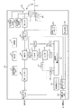
次に、図2を用いて、本発明に係る滅菌装置のハードウエアの構成の一例について説明する。
図2は、本発明に係る滅菌装置のハードウエアの構成の一例を示す図である。
<Description of FIG. 2>
Next, an example of the hardware configuration of the sterilizer according to the present invention will be described with reference to FIG.
FIG. 2 is a diagram showing an example of the hardware configuration of the sterilization apparatus according to the present invention.
本発明に係る滅菌装置100は、演算処理部(MPU等)201と、表示部102と、印刷部103と、ロック動作制御部202と、抽出針動作制御部203と、滅菌室の扉101と、液センサー204と、カートリッジ205と、RF−IDリーダ/ライタ206と、液送ロータリーポンプ207と、濃縮炉208と、気送加圧ポンプ209と、吸気用HEPAフィルタ210と、弁(V1)211と、弁(V3)212と、弁(V4)213と、計量管214と、弁(V2)215と、気化炉216と、弁(V5)217と、弁(V9)227と、弁(V7)226と、滅菌室(真空チャンバーとも言う)219と、気送真空ポンプ220と、排気用HEPAフィルタ221と、滅菌剤分解装置222と、液送ロータリーポンプ223と、排気蒸発炉224とから構成されている。
The
演算処理部(MPU等)201は、演算処理を行い、滅菌装置100を構成する各ハードウエアを制御する。
An arithmetic processing unit (MPU or the like) 201 performs arithmetic processing and controls each hardware constituting the
表示部102、印刷部103、滅菌室の扉101は、既に図1を用いて説明しているため、ここでは説明を省略する。
The
ロック動作制御部202は、カートリッジ取付用扉101の施錠、開錠の動作を行う部であり、カートリッジ取付用扉101を施錠することにより、カートリッジ取付用扉101を開かないようにし、また、カートリッジ取付用扉101を開錠することにより、カートリッジ取付用扉101を開けることができるようにする。
The lock
カートリッジ205は、滅菌剤(過酸化水素、又は過酸化水素溶液の液体)が充填され、密閉された容器である。また、カートリッジ205の下側にはRF−IDの記憶媒体を備えており、その記憶媒体には、該カートリッジを識別する情報としてのシリアル番号と、該カートリッジの製造年月日、該カートリッジが初めて滅菌装置で使用された日時(初回使用日時)、該カートリッジ内に充填されている滅菌剤の残量が記憶されている。
The
抽出針動作制御部203は、カートリッジ内の滅菌剤を吸引するための抽出針(注射針)をカートリッジの上部から刺すために、当該抽出針を動作する部である。
The extraction needle
すなわち、カートリッジ内の滅菌剤を吸引するための抽出針(注射針)をカートリッジの上部から刺す場合は、抽出針(注射針)をカートリッジに向けて、該カートリッジの上部から降ろすように動作することで、抽出針(注射針)をカートリッジの上部から刺すことができる。また、抽出針(注射針)をカートリッジから抜く場合は、該カートリッジの上部に抽出針(注射針)を上げるように動作することで、抽出針(注射針)をカートリッジから抜くことができる。 That is, when an extraction needle (injection needle) for aspirating the sterilizing agent in the cartridge is inserted from the upper part of the cartridge, the extraction needle (injection needle) is directed toward the cartridge and operated to be lowered from the upper part of the cartridge. Thus, the extraction needle (injection needle) can be inserted from the top of the cartridge. When the extraction needle (injection needle) is removed from the cartridge, the extraction needle (injection needle) can be removed from the cartridge by operating to raise the extraction needle (injection needle) above the cartridge.
液センサー204は、カートリッジ205内の液体の滅菌剤が、抽出針(注射針)から液送ロータリーポンプ207、液送ロータリーポンプ223に導通している管(導管)を通っているかを検出する装置である。具体的には、該管に赤外線を照射して得られるスペクトルから滅菌剤が該管を通っているかを検出することができる。
The
RF−IDリーダ/ライタ206は、カートリッジ205の下側に備え付けられているRF−IDから、シリアル番号、製造年月、初回使用日時、滅菌剤の残量を読み取ることができる装置である。また、RF−IDリーダ/ライタ206から、カートリッジ205の下側に備え付けられているRF−IDに、初回使用日時、滅菌剤の残量を書き込むことができる装置である。また、RF−IDリーダ/ライタ206は、カートリッジ取付用扉101の裏にあるカートリッジの取り付け場所の下部に設置されており、カートリッジ205の下側に備え付けられているRF−IDを読み取ること、及び初回使用日時、滅菌剤の残量等のデータをRF−IDに書き込むことが可能である。
The RF-ID reader /
液送ロータリーポンプ207は、濃縮炉208と導管により導通しており、また、液センサ204と導管により導通している。液送ロータリーポンプ207は、カートリッジ205内の液体の滅菌剤をポンプにより吸引して、導管を通して滅菌剤を濃縮炉208に送る装置である。また、液送ロータリーポンプ207は、液センサ204と連携して、カートリッジ205から、滅菌剤の所定量を吸引することができる。
The liquid
濃縮炉208は、液送ロータリーポンプ207と、気送加圧ポンプ209と、計量管214と、排気用HEPAフィルタ221と、計量管214と、それぞれ導管により導通している。濃縮炉208は、後述する図10でも説明するが、液送ロータリーポンプ207から導管を通じて送り込まれた滅菌剤を、ヒーターを用いて加熱し、滅菌剤に含まれる水分などを蒸発(気化)させ滅菌剤を濃縮する。また、気化した水は、気送加圧ポンプ209から導管を通して送り込まれる空気により、排気用HEPAフィルタ221に導通している導管に押し出され、濃縮炉208内から排気される。また、計量管214と濃縮炉208との間の導管の間には弁(1)211が設けられている。
The concentrating
気送加圧ポンプ209は、それぞれ、濃縮炉208と、吸気用HEPAフィルタ210と、導管により導通している。気送加圧ポンプ209は、滅菌装置100の外気(空気)を、吸気用HEPAフィルタ210を介して、吸気用HEPAフィルタ210との導管により導通して濃縮炉208に送る装置である。
The air
吸気用HEPAフィルタ210は、それぞれ、気送加圧ポンプ209と、滅菌室219と、気化炉216と、導管により導通している。吸気用HEPAフィルタ210は、滅菌装置100の外の外気(空気)中のちりやほこり、雑菌などを、HEPA(High Efficiency Particulate Air Filter)フィルタでフィルタリングして空気を清浄する。そして、その清浄された空気は、気送加圧ポンプ209により導管を通して濃縮炉208に送られる。また、清浄された空気は、気化炉216との導管により導通して気化炉216に送り込まれたり、滅菌室219との導管により導通して滅菌室219に送り込まれる。すなわち、吸気用HEPAフィルタ210は、滅菌装置100の外の外気(空気)と導通している。そのため、気送加圧ポンプ209と吸気用HEPAフィルタ210との間の導管と、滅菌室219と吸気用HEPAフィルタ210との間の導管と、気化炉216と吸気用HEPAフィルタ210との間の導管は、吸気用HEPAフィルタ210を介して、外気(空気)と導通している。
The
また、吸気用HEPAフィルタ210と気化炉216との間の導管には、弁(V9)227が設けられている。また、吸気用HEPAフィルタ210と滅菌室219との間の導管には、弁(V7)226が設けられている。
A valve (V9) 227 is provided in the conduit between the
弁(V1)211は、濃縮炉208と計量管214との間の導管に設けられた弁であって、弁を開けることで濃縮炉208と計量管214との間の導管による導通を可能にし、弁を閉めることで濃縮炉208と計量管214との間の導管による導通を不可能にする弁である。
The valve (V1) 211 is a valve provided in a conduit between the concentrating
弁(V3)212は、計量管214と滅菌室219との間の導管に設けられた弁であって、弁を開けることで計量管214と滅菌室219との間の導管による導通を可能にし、弁を閉めることで計量管214と滅菌室219との間の導管による導通を不可能にする弁である。また、この弁は、計量管214の近くに設けられており、少なくとも後述する弁(V4)よりも計量管214側の位置に設けられている。
The valve (V3) 212 is a valve provided in a conduit between the
弁(V4)213は、計量管214と滅菌室219との間の導管に設けられた弁であって、弁を開けることで計量管214と滅菌室219との間の導管による導通を可能にし、弁を閉めることで計量管214と滅菌室219との間の導管による導通を不可能にする弁である。また、この弁は、滅菌室219の近くに設けられており、少なくとも後述する弁(V3)よりも滅菌室210側の位置に設けられている。
The valve (V4) 213 is a valve provided in a conduit between the
本実施例では、弁(V4)213、弁(V3)213の開け閉めにより、計量管と滅菌室との間の導管の導通を可能にするか、不可能にするかを行っているが、弁(V4)213、弁(V3)213のどちらか一方の弁の開け閉めにより、計量管と滅菌室との間の導管の導通を可能にするか、不可能にするかを行うようにしてもよい。 In this embodiment, the valve (V4) 213 and the valve (V3) 213 are opened and closed to enable or disable the conduit between the measuring tube and the sterilization chamber. Whether to open or close one of the valve (V4) 213 and valve (V3) 213 enables or disables the conduit between the measuring tube and the sterilization chamber. Also good.
計量管214は、濃縮炉208と、気化炉216と、滅菌室219のそれぞれとの間の導管により導通している。
The measuring
計量管214は、弁(V1)211を開くことにより、濃縮炉208から滅菌剤が流入し、弁(V3)212、及び弁(V4)213を開くことにより、カートリッジ205内から吸入した不要な空気、及び/又は濃縮炉208内から流入した不要な空気を、計量管214により取り除く装置である。計量管214の詳細については、図10を用いて、後で説明する。
When the valve (V1) 211 is opened, the sterilizing agent flows into the measuring
弁(V2)215は、計量管214と、気化炉216との間の導管に設けられた弁であって、弁を開けることで計量管214と気化炉216との間の導管による導通を可能にし、弁を閉めることで計量管214と気化炉216との間の導管による導通を不可能にする弁である。
The valve (V2) 215 is a valve provided in a conduit between the
気化炉216は、計量管214と、吸気用HEPAフィルタ210と、滅菌室219とのそれぞれとの間の導管により導通している。気化炉216は、本発明の気化室の適用例である。
気化炉216は、気送真空ポンプ220により減圧されることで、滅菌剤を気化させる装置である。
The vaporizing
The vaporizing
弁(V5)217は、気化炉216と、滅菌室219との間の導管に設けられた弁であって、弁を開けることで気化炉216と滅菌室219との間の導管による導通を可能にし、弁を閉めることで気化炉216と滅菌室219との間の導管による導通を不可能にする弁である。
The valve (V5) 217 is a valve provided in a conduit between the vaporizing
弁(V9)227は、気化炉216と吸気用HEPAフィルタ210との間の導管に設けられた弁であって、弁を開けることで気化炉216と吸気用HEPAフィルタ210との間の導管による導通を可能にし、弁を閉めることで気化炉216と吸気用HEPAフィルタ210との間の導管による導通を不可能にする弁である。すなわち、弁(V9)227は、気化炉216と外気(大気)との導通を開閉できる弁である。
The valve (V9) 227 is a valve provided in a conduit between the
弁(V7)226は、滅菌室219と吸気用HEPAフィルタ210との間の導管に設けられた弁であって、弁を開けることで滅菌室219と吸気用HEPAフィルタ210との間の導管による導通を可能にし、弁を閉めることで滅菌室219と吸気用HEPAフィルタ210との間の導管による導通を不可能にする弁である。すなわち、弁(V7)226は、滅菌室219と外気(大気)との導通を開閉できる弁である。
The valve (V7) 226 is a valve provided in a conduit between the
滅菌室(真空チャンバーとも言う)219は、図1でも説明したが、例えば医療用器具などの被滅菌対象物を滅菌する所定の容量の筐体である。滅菌室内の圧力は大気圧から真空圧までの圧力を維持することが可能である。また、滅菌室内の温度は、滅菌処理中において、所定の範囲の温度に維持されている。また、滅菌室219内には、圧力センサーが備えられており、圧力センサーにより滅菌室219内の圧力(気圧)を測定することができる。滅菌装置100は、この圧力センサーにより測定された滅菌室219内の気圧を用いて、滅菌室219内等の圧力(気圧)が所定の気圧になっているかを判定する。
The sterilization chamber (also referred to as a vacuum chamber) 219 is a casing having a predetermined capacity for sterilizing an object to be sterilized such as a medical instrument as described with reference to FIG. The pressure in the sterilization chamber can be maintained from atmospheric pressure to vacuum pressure. Further, the temperature in the sterilization chamber is maintained within a predetermined range during the sterilization process. Further, a pressure sensor is provided in the
気送真空ポンプ220は、滅菌室219内、気化炉216内、計量管214内、計量管214と気化炉216との間の導管内、気化炉216と滅菌室219との間の導管内、計量管214と滅菌室219との間の導管内の空間の気体を吸引して、それぞれの空間内を減圧し真空状態(大気圧より低い圧力の気体で満たされた空間内の状態)にする装置である。
The air
気送真空ポンプ220は、滅菌室219との間で導管により導通されており、排気用HEPAフィルタ221との間で導管により導通されている。
The
排気用HEPAフィルタ221は、気送真空ポンプ220との間で導管により導通されている。また、排気用HEPAフィルタ221は、排気蒸発炉224との間で導管により導通されている。また、排気用HEPAフィルタ221は、滅菌剤分解装置222との間で導管により導通されている。また、排気用HEPAフィルタ221は、濃縮炉208との間で導管により導通されている。
The
排気用HEPAフィルタ221は、気送真空ポンプ220により、滅菌室219内等から吸引された気体を、気送真空ポンプ220との間の導管から送られた気体内のちりやほこり、雑菌などを、HEPA(High Efficiency Particulate Air Filter)フィルタでフィルタリングして、吸引された気体を清浄する。そして、清浄された気体は、滅菌剤分解装置222と排気用HEPAフィルタ221との間の導管を通り、滅菌剤分解装置222に送られ、滅菌剤分解装置222により該気体に含まれる滅菌剤の分子を分解し、分解後の分子を滅菌装置100の外に放出する。
The
また、排気用HEPAフィルタ221は、濃縮炉208と排気用HEPAフィルタ221との間の導管により濃縮炉208から排気される気体を清浄する。この気体は、濃縮炉208で、滅菌剤が過熱されて、気化された水であるが、微量の滅菌剤を含むため、滅菌剤分解装置222と排気用HEPAフィルタ221との間の導管を通り、滅菌剤分解装置222に送られる。そして、滅菌剤分解装置222により該気体に含まれる滅菌剤の分子を分解し、分解後の分子を滅菌装置100の外に放出する。
Further, the
また、排気用HEPAフィルタ221は、排気蒸発炉224から、排気蒸発炉224と排気用HEPAフィルタ221との間の導管を通り送られてくる気化された滅菌剤を清浄する。そして、その洗浄された滅菌剤(気体)は、滅菌剤分解装置222と排気用HEPAフィルタ221との間の導管を通り、滅菌剤分解装置222に送られ、滅菌剤分解装置222により該気体に含まれる滅菌剤の分子を分解し、分解後の分子を滅菌装置100の外に放出する。
Further, the
滅菌剤分解装置222は、排気用HEPAフィルタ221との間の導管により導通されている。滅菌剤分解装置222は、滅菌剤分解装置222と排気用HEPAフィルタ221との間の導管から送られてくる気体に含まれる滅菌剤の分子を分解して、分解して生成される分子を滅菌装置100の外に放出する。
The sterilizing
滅菌剤分解装置222は、例えば、滅菌剤が過酸化水素、又は過酸化水素溶液である場合、気化された過酸化水素を、二酸化マンガンを触媒として用いて、水と酸素に分解することができる装置である。
For example, when the sterilizing agent is hydrogen peroxide or a hydrogen peroxide solution, the sterilizing
液送ロータリーポンプ223は、排気蒸発炉224と導管により導通しており、また、液センサ204と導管により導通している。
The liquid
液送ロータリーポンプ223は、カートリッジ205内の全ての液体の滅菌剤をポンプにより吸引して、液センサ204と液送ロータリーポンプ223との間の導管を通して送られるその全ての滅菌剤を、液送ロータリーポンプ223と排気蒸発炉224との間の導管を通して、排気蒸発炉224に送る装置である。
The liquid
排気蒸発炉224は、液送ロータリーポンプ223と導管により導通しており、また、排気用HEPAフィルタ221と導管により導通している。
The exhaust evaporation furnace 224 is electrically connected to the liquid
排気蒸発炉224は、液送ロータリーポンプ223と排気蒸発炉224との間の導管を通して送られる、カートリッジ205内の全ての液体の滅菌剤を、排気蒸発炉224に備え付けられたヒーターにより加熱し、その滅菌剤の全てを気化させる。そして、気化された滅菌剤は、排気用HEPAフィルタ221と排気蒸発炉224との間の導管を通して、排気用HEPAフィルタ221に送られる。
The exhaust evaporation furnace 224 heats all the liquid sterilizing agents in the
<図4の説明>
次に、図4を用いて、本発明に係る滅菌装置による滅菌処理の各工程の一例について説明する。
<Description of FIG. 4>
Next, an example of each step of the sterilization process by the sterilizer according to the present invention will be described with reference to FIG.
図4に示す各工程(処理)は、滅菌装置100の演算処理部201により滅菌装置内の各装置の動作を制御することにより行われる。
図4は、本発明に係る滅菌装置による滅菌処理の各工程の一例を示す図である。
Each step (process) shown in FIG. 4 is performed by controlling the operation of each device in the sterilization apparatus by the
FIG. 4 is a diagram showing an example of each step of sterilization processing by the sterilization apparatus according to the present invention.
滅菌装置100は、電源が入れられると、まず、RF−IDリーダ/ライタ206が、カートリッジ205の下側に設けられたRF−ID(記憶媒体)から、データを読み取る(ステップS101)。
When the
ステップS101で、RF−ID(記憶媒体)から読み取られるデータとしては、該カートリッジを識別する情報としてのシリアル番号と、該カートリッジの製造年月日と、該カートリッジが滅菌装置で初めて使用された日時(初回使用日時)と、該カートリッジ内に充填されている滅菌剤の残量とがある。すなわち、カートリッジ205に設けられたRF−ID(記憶媒体)には、予め、シリアル番号、製造年月日、初回使用日時、滅菌剤の残量が記憶されている。
In step S101, the data read from the RF-ID (storage medium) includes a serial number as information for identifying the cartridge, the date of manufacture of the cartridge, and the date and time when the cartridge was first used in the sterilizer. (First use date and time) and the remaining amount of sterilant filled in the cartridge. That is, an RF-ID (storage medium) provided in the
次に、滅菌装置100は、ステップS101でRF−IDからデータが読み取れたと判定された場合は(ステップS102:YES)、滅菌装置100内のカートリッジの取り付け場所にカートリッジが設置されていると判断し、カートリッジ取付用扉101を施錠する(ステップS103)。
Next, when it is determined in step S101 that data has been read from the RF-ID (step S102: YES), the
そして、滅菌装置100は、カートリッジ内に滅菌1回分の滅菌剤の所定の量があるか否かを判定する。具体的には、RF−IDから取得した滅菌剤の残量が、滅菌1回分の所定の量よりも多いか否かを判定する。すなわち、滅菌剤の残量が、滅菌1回分の所定の量よりも多いと判定された場合は、カートリッジ内に滅菌1回分の滅菌剤の所定の量がある(十分な滅菌処理を実行できる)と判断し(ステップS104:YES)、ステップS105の処理を行う。一方、滅菌剤の残量が、滅菌1回分の所定の量(例えば、8ミリリットル)よりも少ないと判定され場合は、カートリッジ内に滅菌1回分の滅菌剤の所定の量がない(十分な滅菌処理を実行できない)と判断し(ステップS104:NO)、ステップS112の処理を行う。
Then, the
滅菌装置100は、ステップS105において、RF−IDから取得したカートリッジの製造年月日から、所定の期間(例えば、13か月)を経過しているかを判断する。
In step S105, the
そして、製造年月日から所定の期間を経過していると判定された場合は(ステップS105:YES)、十分な滅菌処理を実行できないと判定し、ステップS112の処理を行う。一方、製造年月日から所定の期間を経過していないと判定された場合は(ステップS105:NO)、十分な滅菌処理を実行できると判定し、ステップS106の処理を行う。 If it is determined that a predetermined period has elapsed since the date of manufacture (step S105: YES), it is determined that sufficient sterilization processing cannot be performed, and the process of step S112 is performed. On the other hand, when it is determined that the predetermined period has not elapsed since the date of manufacture (step S105: NO), it is determined that sufficient sterilization processing can be performed, and the process of step S106 is performed.
滅菌装置100は、ステップS106において、RF−IDから取得した初回使用日時から、所定の期間(例えば、2週間)を経過しているかを判断する。
In step S106, the
そして、RF−IDから取得した初回使用日時から、所定の期間(例えば、2週間)を経過していると判定された場合は(ステップS106:YES)、十分な滅菌処理を実行できないと判定し、ステップS112の処理を行う。一方、所定の期間(例えば、2週間)を経過していないと判定された場合は(ステップS106:NO)、十分な滅菌処理を実行できると判定し、ステップS107の処理を行う。 If it is determined that a predetermined period (for example, two weeks) has elapsed from the first use date and time acquired from the RF-ID (step S106: YES), it is determined that sufficient sterilization processing cannot be performed. Then, the process of step S112 is performed. On the other hand, when it is determined that a predetermined period (for example, two weeks) has not elapsed (step S106: NO), it is determined that sufficient sterilization processing can be performed, and the process of step S107 is performed.
滅菌装置100は、ステップS107において、滅菌開始画面(図3の301)を表示部102に表示する。
図3は、滅菌装置100の表示部102に表示される画面の一例を示す図である。
The
FIG. 3 is a diagram illustrating an example of a screen displayed on the
滅菌開始画面301には、「滅菌開始ボタン」が表示されている。ステップS107で表示される滅菌開始画面301内の「滅菌開始ボタン」302は、ユーザにより押下可能に(アクティブに)なっている。
On the
そして、滅菌装置100は、ユーザにより、「滅菌開始ボタン」302が押下されると(ステップS108:YES)、滅菌モード選択画面(図3の303)を表示部102に表示する。
Then, when the “sterilization start button” 302 is pressed by the user (step S108: YES), the
滅菌モード選択画面303には、「滅菌剤を濃縮して滅菌するモード」ボタン304と、「滅菌剤を濃縮しないで滅菌するモード」ボタン305とが表示されている。
The sterilization
滅菌装置100は、「滅菌剤を濃縮して滅菌するモード」ボタン304と、「滅菌剤を濃縮しないで滅菌するモード」ボタン305のどちらか一方の選択をユーザから受け付け(ステップS110)、ユーザにより選択されたボタンのモードに従った滅菌処理(ステップS111)を行う。滅菌処理(ステップS111)の詳細は、図5を用いて、後で説明する。
The
このように、ユーザの指示により、滅菌処理するモードを1台の滅菌装置で切り替えて使用することが可能となる。すなわち、「滅菌剤を濃縮して滅菌するモード」ボタン304がユーザにより押下された場合は、滅菌剤を濃縮して、滅菌処理を行い、「滅菌剤を濃縮しないで滅菌するモード」ボタン305が押下された場合は、滅菌剤を濃縮しないで、滅菌処理を行う。
Thus, it becomes possible to switch and use the sterilization processing mode with one sterilization apparatus in accordance with a user instruction. That is, when the “concentrate sterilant and sterilize”
そして、滅菌装置100は、滅菌処理(ステップS111)が終了すると、ステップS110に処理を戻す。
Then, when the sterilization process (step S111) ends, the
また、滅菌装置100は、ステップS112において、滅菌開始画面(図3の301)を表示部102に表示する。ただし、ステップS112で表示される滅菌開始画面(図3の301)内の「滅菌開始ボタン」302は、ユーザにより押下出来ないように表示されている(「滅菌開始ボタン」302がアクティブではない)。そのため、ユーザによる、滅菌処理の開始指示を受け付けないようにすること可能となる。
The
そして、滅菌装置100は、ステップS101でRF−IDから取得したシリアル番号から、カートリッジの取り付け場所に設置してあるカートリッジが、既に滅菌剤の排出処理済みのカートリッジであるか否かを判定する(ステップS113)。具体的には、滅菌装置100内のメモリ(記憶部)には、既に滅菌剤の排出処理済みのカートリッジを識別するシリアル番号が記憶されており、ステップS101でRF−IDから取得したシリアル番号が、該メモリ(記憶部)に記憶されているシリアル番号に一致するか否かを判定することにより、現在、滅菌装置100に取り付けられているカートリッジが、既に滅菌剤の排出処理済みのカートリッジであるか否かを判定する。
Then, the
現在、滅菌装置100に取り付けられているカートリッジが、既に滅菌剤の排出処理済みのカートリッジであると判定された場合は(ステップS113:YES)、ステップS115の処理を行う。一方、既に滅菌剤の排出処理済みのカートリッジではないと判定された場合は(ステップS113:NO)、カートリッジ内に残っている液体の滅菌剤の残量の全てを吸い取り、その全ての滅菌剤を分解処理して、滅菌装置100の外に放出する、滅菌剤の排出処理(ステップS114)を行い、その後、ステップS115の処理を行う。ステップS114の滅菌剤の排出処理の詳細は、図9を用いて、後で説明する。
If it is determined that the cartridge currently attached to the
ステップS114の処理を行うと、滅菌装置100内のメモリ(記憶部)に、既に滅菌剤の排出処理済みのカートリッジを識別するシリアル番号として、ステップS101で読み取ったシリアル番号を記憶する。
滅菌装置100は、ステップ115において、カートリッジ取付用扉101を開錠する。
When the process of step S114 is performed, the serial number read in step S101 is stored in the memory (storage unit) in the
In step 115, the
また、滅菌装置100は、ステップS102において、ステップS101でRF−IDからデータが読み取れなかったと判定された場合は(ステップS102:NO)、滅菌装置100内のカートリッジの取り付け場所にカートリッジが設置されていないと判断し、図11に示すカートリッジ取付要求画面1101を表示する(ステップS116)。
If it is determined in step S102 that data could not be read from the RF-ID in step S101 (step S102: NO), the
図11は、滅菌装置100の表示部102に表示されるカートリッジ取付要求画面1101の一例を示す図である。
カートリッジ取付要求画面1101には、「OK」ボタン1102が表示されている。
FIG. 11 is a diagram illustrating an example of a cartridge
An “OK”
そして、滅菌装置100は、カートリッジ取付要求画面1101の「OK」ボタン1102がユーザにより押下されたかを判定し(ステップS117)、「OK」ボタン1102が押下された場合は(YES)、カートリッジ取付用扉101を開錠し(ステップS118)、処理をステップS101に戻す。一方、「OK」ボタン1102が押下されていない場合は(NO)、カートリッジ取付要求画面1101を表示し続ける。
Then, the
カートリッジ取付用扉101の開錠、及び施錠の処理は、ロック動作制御部202による動作により行われる。
The unlocking and locking process of the
<図5の説明>
次に、図5を用いて、図4のS111に示す滅菌処理の詳細処理の一例について説明する。
図5は、図4のS111に示す滅菌処理の詳細処理の一例を示す図である。
<Description of FIG. 5>
Next, an example of detailed processing of the sterilization processing shown in S111 of FIG. 4 will be described using FIG.
FIG. 5 is a diagram showing an example of detailed processing of the sterilization processing shown in S111 of FIG.
図5に示す各工程(処理)は、滅菌装置100の演算処理部201により滅菌装置内の各装置の動作を制御することにより行われる。
Each process (process) shown in FIG. 5 is performed by controlling the operation of each apparatus in the sterilization apparatus by the
まず、滅菌装置100は、ステップS501において、気送真空ポンプ220を動作し、滅菌室219の気体を吸引し、滅菌室219内の気圧が所定の気圧(45パスカル)まで減圧する滅菌前工程の処理を行う。滅菌前工程の処理の詳細な処理は、図6を用いて後で説明する。
First, in step S501, the
そして、滅菌装置100は、ステップS502において、滅菌室219に、滅菌剤を入れて、被滅菌対象物を滅菌する滅菌工程の処理を行う。滅菌工程の処理の詳細な処理は、図7を用いて後で説明する。
In step S502, the
次に、滅菌装置100は、ステップS503において、滅菌室219内、及び気化炉216内に含まれている滅菌剤を取り除くための換気工程の処理を行う。換気工程の処理の詳細な処理は、図8を用いて後で説明する。
Next, in step S503, the
<図6の説明>
次に、図6を用いて、図5のS501に示す滅菌前工程の詳細処理の一例について説明する。
図6は、図5のS501に示す滅菌前工程の詳細処理の一例を示す図である。
<Description of FIG. 6>
Next, an example of detailed processing of the pre-sterilization process shown in S501 of FIG. 5 will be described using FIG.
FIG. 6 is a diagram showing an example of detailed processing of the pre-sterilization process shown in S501 of FIG.
図6に示す各工程(処理)は、滅菌装置100の演算処理部201により滅菌装置内の各装置の動作を制御することにより行われる。
Each process (process) shown in FIG. 6 is performed by controlling the operation of each apparatus in the sterilization apparatus by the
まず、滅菌装置100は、気送真空ポンプ220を動作し、滅菌室219の気体を吸引する処理を開始する(ステップS601)。
First, the
そして、滅菌装置100は、ステップS602において、滅菌室219内の圧力(気圧)が、所定の気圧(45パスカル)まで減圧されているかを判定する。具体的には、滅菌室219内に備えられた圧力センサーにより測定されている滅菌室219内の圧力(気圧)が、所定の気圧(45パスカル)まで減圧されているかを判定する。
In step S602, the
ステップS602において、滅菌室219内の圧力(気圧)が、所定の気圧(45パスカル)まで減圧されていないと判定された場合は(NO)、気送真空ポンプ220を引き続き動作させ、滅菌室219の気体を吸引し、滅菌室219内の圧力(気圧)を減圧する。
If it is determined in step S602 that the pressure (atmospheric pressure) in the
一方、ステップS602において、滅菌室219内の圧力(気圧)が、所定の気圧(45パスカル)まで減圧されていると判定された場合は(YES)、気送真空ポンプ220を引き続き動作させ、滅菌室219の気体を吸引し、ステップS502の処理を開始する。
On the other hand, if it is determined in step S602 that the pressure (atmospheric pressure) in the
<図7の説明>
次に、図7を用いて、図5のS502に示す滅菌工程の詳細処理の一例について説明する。
図7は、図5のS502に示す滅菌工程の詳細処理の一例を示す図である。
<Explanation of FIG. 7>
Next, an example of detailed processing of the sterilization process shown in S502 of FIG. 5 will be described using FIG.
FIG. 7 is a diagram showing an example of detailed processing of the sterilization process shown in S502 of FIG.
図7に示す各工程(処理)は、滅菌装置100の演算処理部201により滅菌装置内の各装置の動作を制御することにより行われる。
Each process (process) shown in FIG. 7 is performed by controlling the operation of each apparatus in the sterilization apparatus by the
まず、滅菌装置100は、弁(V5)217を開けて、滅菌室219と気化炉216との間の導管を導通させる(ステップS701)。これにより、現在、気送真空ポンプ220により滅菌室219の気体を吸引し減圧しているため、滅菌室219内、及び気化炉216内の減圧を開始する(ステップS702)。
First, the
そして、滅菌装置100は、ステップS110で、「滅菌剤を濃縮して滅菌するモード」ボタン304と、「滅菌剤を濃縮しないで滅菌するモード」ボタン305のどちらが押下されたのかを判定する(ステップS703)。「滅菌剤を濃縮して滅菌するモード」ボタン304が押下されたと判定された場合は(YES)、ステップS704の処理を行い、「滅菌剤を濃縮しないで滅菌するモード」ボタン305が押下されたと判定された場合は(NO)、ステップS728の処理を行う。
Then, in step S110, the
ここでは、まず、「滅菌剤を濃縮して滅菌するモード」ボタン304が押下された場合(滅菌剤を濃縮して滅菌処理する場合)について、説明する。
Here, first, a case where the “mode for sterilizing and sterilizing sterilizing agent”
滅菌装置100は、ステップS704において、液送ロータリーポンプ207を動作し、カートリッジ205内の滅菌剤を、所定量(2ミリリットル)吸い取る。そして、吸い取られた所定量の滅菌剤を、濃縮炉208に入れる。ここで吸い取る所定量の滅菌剤は、滅菌室219内の空間を滅菌剤で飽和状態にさせることができる量である。
In step S704, the
そして、滅菌装置100は、ステップS705において、カートリッジの取り付け場所に取り付けられているカートリッジ205のRF−IDに、カートリッジ205内に残っている滅菌剤の残量を書き込む。具体的には、ステップS101で読み取ったカートリッジ205内の滅菌剤の残量から、ステップS704でカートリッジ205から吸い取った所定量(2ミリリットル)を引いた値をRF−IDに記憶する。
In step S705, the
また、滅菌装置100は、ステップS101でRF−IDから読み取られた初回使用日時(カートリッジが滅菌装置で初めて使用された日時)に、日時を示す情報が含まれていない場合は、今回、カートリッジが滅菌装置で初めて使用されたと判定する。このようにカートリッジが滅菌装置で初めて使用されたと判定された場合のみ、現在の日時情報もRF−IDに書き込む。
In addition, the
次に、滅菌装置100は、滅菌装置100に電源が入っているときは、常に、濃縮炉208に備え付けられたヒータを加熱するため、ステップS704で濃縮炉208に入れられた滅菌剤は、そのヒータの熱により、加熱され、濃縮炉208内の滅菌剤に含まれる水分を蒸発させる(ステップS706)。
Next, since the
すなわち、滅菌剤が過酸化水素水(過酸化水素水溶液とも言う)である場合、濃縮炉208に備え付けられたヒータを、ここでは、具体的には、80度で温める。これにより、主に水分を蒸発(気化)させることができ、滅菌剤を濃縮させることが可能となる。
That is, when the sterilizing agent is a hydrogen peroxide solution (also referred to as an aqueous hydrogen peroxide solution), the heater provided in the
次に、滅菌装置100は、ステップS707において、ステップS704で濃縮炉208に滅菌剤を入れてから所定の時間(6分)が経過したかを判定する。そして、濃縮炉208に滅菌剤を入れてから所定の時間が経過したと判定されると(YES)、ステップS708の処理を行う。一方、濃縮炉208に滅菌剤を入れてから所定の時間が経過していない場合は(NO)、引き続き、濃縮炉208に滅菌剤を入れたままにしておき、引き続き滅菌剤を濃縮する。
Next, in step S707, the
次に、滅菌装置100は、ステップS708において、滅菌室219内、及び気化炉216内の気圧が、所定の気圧(500パスカル)まで減圧されたかを判定する。
Next, in step S708, the
そして、滅菌装置100は、滅菌室219内、及び気化炉216内の気圧が、所定の気圧まで減圧された場合は(YES)、ステップS709において、弁(V3)212と、弁(V4)213とを所定時間開ける(弁(V3)212と、弁(V4)213とを所定時間(3秒)開けて弁(V3)212と、弁(V4)213を閉じる)ことで、計量管214内を減圧する。一方、滅菌室219内、及び気化炉216内の気圧が、所定の気圧まで減圧されていない場合は(NO)、引き続き滅菌剤の濃縮を行う。
When the pressure in the
そして、次に、滅菌装置100は、ステップS710において、ステップS709で、弁(V3)212と弁(V4)213とを所定時間開けて弁(V3)212と弁(V4)213を閉じた後に、弁(V1)を所定時間(3秒)開けると、濃縮炉208(外部)の気圧よりも計量管214内の気圧の方が低いので濃縮炉208に入っている滅菌剤が計量管214に吸い込まれて入る(ステップS710)。ここでは、弁(V1)を所定時間開けて閉じることで、濃縮炉208に入っている滅菌剤が計量管214に吸い込まれて入る。ここでは、滅菌剤だけではなく、濃縮炉208内の空気も一緒に計量管214内に吸い込まれてくる。
そして、この後も、引き続き、気送真空ポンプ220により、滅菌室219内が減圧されている。
In step S710, the
After that, the inside of the
そのため、滅菌室219内の気圧は、計量管内の気圧よりも低くなる。具体的には、滅菌室219内の気圧は、400Paであり、計量管内の気圧は大気圧(101325Pa)位の値である。計量管内の気圧は大気圧近くまで上がる理由は、滅菌剤だけではなく、濃縮炉208内の空気も一緒に計量管214内に吸い込まれてくるためである。
Therefore, the atmospheric pressure in the
次に、滅菌装置100は、ステップS711において、弁(V3)212と、弁(V4)213とを所定時間(3秒)開けて、計量管内の空気(液体の滅菌剤は含まない)を滅菌室219に吸い出される。すなわち、ここでは、弁(V3)212と弁(V4)213とを開けて該所定時間が経過すると、弁(V3)212と弁(V4)213とを閉じる。
Next, in step S711, the
次に、滅菌装置100は、滅菌室219内、及び気化炉216内の気圧が所定の気圧(80Pa)まで減圧されているかを判定し、減圧されていると判定された場合に(ステップS712)、弁(V5)217を閉める(ステップS713)。
Next, the
そして、滅菌装置100は、弁(V2)215を開ける(ステップS714)。これにより、計量管214内の滅菌剤は、気化炉216に吸い込まれ、気化炉内216で気化する。
ここで、滅菌剤は、分子クラスターとして気化炉内で気化する。
Then, the
Here, the sterilizing agent is vaporized in the vaporizer as a molecular cluster.
滅菌室内は、気化炉よりも大きい容積であり、気化炉内では、滅菌剤は、分子クラスターとして気化される。これは、気化炉の容積が滅菌室内より小さいため、滅菌室内の滅菌剤の分子間の距離が近く分子間力により、分子クラスターを形成しやすいためである。 The inside of the sterilization chamber has a volume larger than that of the vaporizing furnace, and in the vaporizing furnace, the sterilizing agent is vaporized as a molecular cluster. This is because the volume of the vaporizing furnace is smaller than that in the sterilization chamber, and the distance between the molecules of the sterilant in the sterilization chamber is so close that molecular clusters are easily formed due to intermolecular forces.
このときも引き続き、気送真空ポンプ220は、滅菌室219内の気体を吸引し、滅菌室219内を減圧している。計量管214内の滅菌剤が吸い込まれた気化炉216内は、気圧が上昇する。
すなわち、気化炉216内の気圧は、滅菌室219内の気圧よりも高くなる。
Also at this time, the
That is, the atmospheric pressure in the vaporizing
次に、滅菌装置100は、滅菌室219内の気圧が、所定の気圧(50Pa)まで減圧され、かつ、ステップS714で弁(V2)215を開けてから所定時間が経過したかを判定し(ステップS715)、滅菌室219内の気圧が、所定の気圧(50Pa)まで減圧され、かつ、ステップS714で弁(V2)215を開けてから所定時間が経過した場合は(YES)、気送真空ポンプ220による滅菌室219内の吸引(真空引き)を停止して(ステップS716)、弁(V5)217を開ける(ステップS717)。これにより、滅菌室219内に気化した滅菌剤が拡散し、被滅菌対象物を滅菌することができる。
これは、気化炉216内の気圧よりも、滅菌室219内の気圧(50Pa)の方が、低いため拡散する。
Next, the
This diffuses because the atmospheric pressure (50 Pa) in the
ここで拡散する滅菌剤は、気化炉内の分子クラスターが更に細分化され、より滅菌剤を滅菌室内に拡散させることができ、滅菌作用を高めることが可能となる。
また、被滅菌対象物などの細かい内腔などを効果的に滅菌することが出来るようになる。
Here, the sterilizing agent that diffuses further subdivides the molecular clusters in the vaporization furnace, so that the sterilizing agent can be further diffused into the sterilization chamber, and the sterilization effect can be enhanced.
In addition, it becomes possible to effectively sterilize a fine lumen of an object to be sterilized.
そして、ステップS717で、弁(V5)217を開けてから、所定時間が経過したかを判定し、弁(V5)217を開けてから、所定時間(330秒)が経過したと判定されると(ステップS718:YES)、弁(V9)227を開ける(ステップS719)。 In step S717, it is determined whether a predetermined time has elapsed since the valve (V5) 217 was opened. If it is determined that a predetermined time (330 seconds) has elapsed since the valve (V5) 217 was opened. (Step S718: YES), the valve (V9) 227 is opened (Step S719).
これにより、滅菌装置100の外の気圧よりも気化炉216内、及び滅菌室219内の気圧の方が低いため、吸気用HEPAフィルタで清浄された、滅菌装置100の外の外気(空気)が、気化炉216内に吸い込まれる。そして、気化炉216内に送り込まれた空気により、気化炉216内に気体として充満している滅菌剤、及び、気化炉216の内部の表面に付着した滅菌剤が、滅菌室219内に送り込まれ、滅菌室219内にある被滅菌対象物に対する滅菌作用が高まる。すなわち、例えば、これにより、被滅菌対象の細いチューブなどの奥などの滅菌し難い部分についての滅菌作用が高まる。
Thereby, since the atmospheric pressure in the vaporizing
そして、滅菌装置100は、ステップS719で、弁(V9)227を開けてから所定の時間(15秒)が経過すると、弁(V7)226を開けて、更に、吸気用HEPAフィルタ210で清浄された、滅菌装置100の外の外気(空気)が、滅菌室219内に吸い込まれる。これは、滅菌装置100の外の気圧よりも滅菌室219内、気化炉216内の気圧の方が低いため、滅菌装置100の外の外気(空気)が、滅菌室219内に吸い込まれる。
これにより、被滅菌対象の細いチューブなどの奥などの滅菌し難い部分についての滅菌作用が高まる。
In step S719, the
Thereby, the sterilization effect | action about the parts which are hard to sterilize, such as the backs, such as a thin tube to be sterilized, increases.
次に、滅菌装置100は、滅菌室219内、及び気化炉216内が大気圧まで上昇したかを判定し、大気圧まで上昇したと判定した場合に(ステップS721:YES)、弁(V2)215を閉める。
Next, the
次に、滅菌装置100は、弁(V7)226を閉め(ステップS723)、気送真空ポンプ220による滅菌室219内の吸引(真空引き)を再開する(ステップS724)。これにより、吸気用HEPAフィルタ210で清浄された、滅菌装置100の外の外気(空気)が、気化炉216内に吸い込まれる。そして、気化炉216内に送り込まれた空気により、気化炉216内に気体として充満している滅菌剤、及び、気化炉216の内部の表面に付着した滅菌剤が、更に、滅菌室219内に送り込まれる。
Next, the
これにより、被滅菌対象の細いチューブなどの奥などの滅菌し難い部分についての滅菌作用が高まると共に、気化炉216内の滅菌剤を効果的に減少させることが可能となる。
As a result, the sterilization effect on a portion that is difficult to sterilize such as the back of a thin tube to be sterilized is enhanced, and the sterilizing agent in the vaporizing
そして、滅菌装置100は、ステップS724で、気送真空ポンプ220による滅菌室219内の吸引(真空引き)を再開してから、所定時間(15秒)後に、弁(V9)227を閉める(ステップS725)。
The
このときも引き続き、気送真空ポンプ220による滅菌室219内の吸引(真空引き)を行っており、ステップS725により、滅菌室219内、及び気化炉216内が密閉され、滅菌室219内、及び気化炉216内を減圧することとなる(ステップS726)。
At this time, suction (evacuation) in the
次に滅菌装置100は、所定回数(例えば、4回)、ステップS702からステップS726の処理を実行したかを判定し(ステップS727)、実行したと判定された場合は(YES)、ステップS503の処理を行う。一方、ステップS702からステップS726の処理を、所定回数実行していないと判定された場合は、ステップS702以降の処理を再度行う。このように、所定回数、ステップS702からステップS726の処理を実行することで、被滅菌対象物に対する滅菌作用の効果が高まり、被滅菌対象物を十分に滅菌することが可能となる。
Next, the
次に、ステップS703で、「滅菌剤を濃縮しないで滅菌するモード」ボタン305が押下されたと判定された場合(滅菌剤を濃縮しないで滅菌処理する場合)について、説明する。
Next, a case where it is determined in step S703 that the “mode for sterilization without concentrating sterilant”
滅菌装置100は、ステップS703で、「滅菌剤を濃縮しないで滅菌するモード」ボタン305が押下されたと判定された場合(NO)、滅菌室219内と気化炉216内の気圧が所定の気圧(1000Pa)にまで減圧されたかを判定する(ステップS728)。
When it is determined in step S703 that the “mode for sterilization without concentrating sterilizing agent”
そして、滅菌装置100は、滅菌室219内と気化炉216内の気圧が所定の気圧(100Pa)にまで減圧されたと判定された場合に(ステップS728:YES)、液送ロータリーポンプ207を動作し、カートリッジ205内の滅菌剤を、所定量(2ミリリットル)吸い取る。そして、吸い取られた所定量の滅菌剤を、濃縮炉208に入れる(ステップS729)。
When it is determined that the pressure in the
ここで吸い取る所定量の滅菌剤は、滅菌室219内の空間を滅菌剤で飽和状態にさせることができる量である。
The predetermined amount of the sterilizing agent sucked out here is an amount that can saturate the space in the
次に、滅菌装置100は、ステップS730において、カートリッジの取り付け場所に取り付けられているカートリッジ205のRF−IDに、カートリッジ205内に残っている滅菌剤の残量を書き込む。具体的には、ステップS101で読み取ったカートリッジ205内の滅菌剤の残量から、ステップS729でカートリッジ205から吸い取った所定量(2ミリリットル)を引いた値をRF−IDに記憶する。
Next, in step S730, the
また、滅菌装置100は、ステップS730において、ステップS101でRF−IDから読み取られた初回使用日時(カートリッジが滅菌装置で初めて使用された日時)に、日時を示す情報が含まれていない場合は、今回、カートリッジが滅菌装置で初めて使用されたと判定する。このようにカートリッジが滅菌装置で初めて使用されたと判定された場合のみ、現在の日時情報もRF−IDに書き込む。
In addition, in step S730, the
そして、滅菌装置100は、ステップS730の処理を行うと、既に説明したステップS709以降の処理を行う。
And if the
ステップS728では、滅菌室219内が1000Paになったら、ステップS729で滅菌剤を吸い始め、ステップS729で滅菌剤を吸い終わる頃には500Paを下回るため、効率的にS709へ移行することができる。
In step S728, when the inside of the
このように、滅菌室219内、及び気化炉216内の気圧が、計量管214内の減圧を開始する所定の気圧(1000パスカル)まで減圧された後に、吸い取られた所定量の滅菌剤を濃縮炉208に入れ、直ぐにステップS709で計量管214内を減圧することができ、その後、ステップS710で濃縮炉208内の滅菌剤を計量管に入れるので、濃縮炉208から、計量管214に直ぐに滅菌剤を入れることが可能となる。すなわち、滅菌剤が濃縮炉208で濃縮されることなく、計量管214に入れることが可能となる。
As described above, after the pressure in the
<図8の説明>
次に、図8を用いて、図5のS503に示す換気工程の詳細処理の一例について説明する。
図8は、図5のS503に示す換気工程の詳細処理の一例を示す図である。
<Description of FIG. 8>
Next, an example of detailed processing of the ventilation process shown in S503 of FIG. 5 will be described with reference to FIG.
FIG. 8 is a diagram showing an example of detailed processing of the ventilation process shown in S503 of FIG.
図8に示す各工程(処理)は、滅菌装置100の演算処理部201により滅菌装置内の各装置の動作を制御することにより行われる。
まず、滅菌装置100は、弁V(7)226を開ける(ステップS801)。
Each process (process) shown in FIG. 8 is performed by controlling the operation of each apparatus in the sterilization apparatus by the
First, the
そして、滅菌装置100は、気送真空ポンプ220による滅菌室219内の吸引(真空引き)を引き続き行う(ステップS802)。
Then, the
ステップS802で、気送真空ポンプ220による滅菌室219内の吸引(真空引き)を開始してから、所定時間を経過すると、弁V(7)226を閉めて(ステップS804)、気送真空ポンプ220による滅菌室219内の吸引(真空引き)を行う。これにより、滅菌室219内が減圧される。
In step S802, when a predetermined time has elapsed after the suction (evacuation) in the
次に、滅菌装置100は、滅菌室219内が所定の気圧(50Pa)まで減圧されると(ステップS806:YES)、弁V(7)226を開ける(ステップS807)。これにより、吸気用HEPAフィルタ210で清浄された、滅菌装置100の外の外気(空気)が、滅菌室219内に吸い込まれる。これは、滅菌装置100の外の気圧よりも滅菌室219内の気圧の方が低いため、滅菌装置100の外の外気(空気)が、滅菌室219内に吸い込まれる。
Next, when the inside of the
そして、滅菌装置100は、滅菌室219内の気圧が、大気圧まで上昇したかを判定し、滅菌室219内の気圧が、大気圧まで上昇したと判定された場合(ステップS808:YES)、ステップS804からステップS808の処理を所定回数(例えば、4回)行ったかを判定し(ステップS809)、ステップS804からステップS808の処理を所定回数(例えば、4回)行った場合は(YES)、弁V(7)226を閉めて(ステップS810)、換気工程を終了する。
Then, the
一方、ステップS804からステップS808の処理を所定回数(例えば、4回)行っていない場合は(NO)、再度、ステップS804の処理から行う。 On the other hand, if the processing from step S804 to step S808 has not been performed a predetermined number of times (for example, 4 times) (NO), the processing from step S804 is performed again.
これにより、滅菌室219内の表面に付着している滅菌剤、及び、滅菌室219内に気体として残っている滅菌剤を気送真空ポンプ220により吸引される。ここで吸引された気体(滅菌剤を含む)は、排気用HEPAフィルタ221を通り、滅菌剤分解装置222で滅菌剤は分解され、分解後の分子が外部に放出される。
Thereby, the sterilizing agent adhering to the surface in the
<図9の説明>
次に、図9を用いて、図4のS114に示す滅菌排出処理の詳細処理の一例について説明する。
図9は、図4のS114に示す滅菌排出処理の詳細処理の一例を示す図である。
<Description of FIG. 9>
Next, an example of detailed processing of the sterilization discharge processing shown in S114 of FIG. 4 will be described using FIG.
FIG. 9 is a diagram showing an example of detailed processing of the sterilization discharge processing shown in S114 of FIG.
図8に示す各工程(処理)は、滅菌装置100の演算処理部201により滅菌装置内の各装置の動作を制御することにより行われる。
Each process (process) shown in FIG. 8 is performed by controlling the operation of each apparatus in the sterilization apparatus by the
まず、滅菌装置100は、液送ロータリーポンプ223により、カートリッジ205内の全ての液体の滅菌剤をポンプにより吸引して、液センサ204と液送ロータリーポンプ223との間の導管を通して送られるその全ての滅菌剤を、液送ロータリーポンプ223と排気蒸発炉224との間の導管を通して、排気蒸発炉224内に送る(ステップS901)。
First, the
そして、滅菌装置100は、排気蒸発炉224により、液送ロータリーポンプ223と排気蒸発炉224との間の導管を通して送られる全ての液体の滅菌剤(排気蒸発炉224内に溜められた滅菌剤)を、排気蒸発炉224に備え付けられたヒーターにより加熱し、その滅菌剤の全てを気化させる。そして、気化された滅菌剤は、排気用HEPAフィルタ221と排気蒸発炉224との間の導管を通して、排気用HEPAフィルタ221に送られる(ステップS902)。
The
ここで、排気蒸発炉224に備え付けられたヒーターは、滅菌剤(過酸化水素)の沸点(過酸化水素の沸点は141度)よりも高い温度に加熱されている。そのため、排気蒸発炉224により、滅菌剤は全て気化されることとなる。 Here, the heater provided in the exhaust evaporation furnace 224 is heated to a temperature higher than the boiling point of the sterilant (hydrogen peroxide) (the boiling point of hydrogen peroxide is 141 degrees). Therefore, all of the sterilizing agent is vaporized by the exhaust evaporation furnace 224.
そして、滅菌装置100は、排気用HEPAフィルタ221により、排気蒸発炉224と排気用HEPAフィルタ221との間の導管を通り送られてくる気化された滅菌剤を清浄し、清浄された気体(滅菌剤を含む)は、滅菌剤分解装置222と排気用HEPAフィルタ221との間の導管を通り、滅菌剤分解装置222に送られる。
Then, the
そして、滅菌剤分解装置222は、滅菌剤分解装置222と排気用HEPAフィルタ221との間の導管から送られてくる気体に含まれる滅菌剤の分子を分解して、分解して生成される分子を滅菌装置100の外に放出する(ステップS903)。
The sterilizing
<図10の説明> <Description of FIG. 10>
次に、図10を用いて、本発明に係る滅菌装置100の濃縮炉208、弁(V1)211、弁(V3)212、弁(V4)213、計量管214、弁(V2)215、気化炉216、弁(V5)217、弁(V9)227のハードウエア構成に係るブロック構成について説明する。
Next, referring to FIG. 10, the
図10は、本発明に係る滅菌装置100の濃縮炉208、弁(V1)211、弁(V3)212、弁(V4)213、計量管214、弁(V2)215、気化炉216、弁(V5)217、弁(V9)227のハードウエア構成に係るブロック構成図の一例を示す図である。
10 shows a
図10に示す各ハードウエアは、図2に示す各ハードウエアと同一のハードウエアについては、同一の符号を付している。 In the hardware shown in FIG. 10, the same reference numerals are assigned to the same hardware as the hardware shown in FIG.
ステップS704、ステップS729で、液送ロータリーポンプ207を動作し、カートリッジ205内の滅菌剤を、所定量(2ミリリットル)吸い取り、吸い取られた所定量の滅菌剤を、濃縮炉208に入れられる。
In step S704 and step S729, the liquid feeding
ステップS706では、濃縮炉208は、図10に示すように、濃縮炉208の下部にヒータが設けられており、このヒータの熱により、滅菌剤が加熱される。滅菌剤が過酸化水素水溶液の場合、このヒータの熱により、水が気化される。そして、気化した水は、気送加圧ポンプ209から導管を通して送り込まれる空気により、排気用HEPAフィルタ221に導通している導管に押し出され、濃縮炉208内から排気される。これにより、滅菌剤(過酸化水素水溶液)が濃縮される。
図7で説明した通り、ステップS710で、濃縮炉208内の滅菌剤は、計量管214内に入る。
この計量管214は、図10に示すように、直管部1001と枝管部1002とから構成されている。
直管部1001は、直線の管状の部分である。直管部1001の管は、重力方向に配置されている。
また、枝管部1002は、直管部1001の中間部又は上部から、枝状に延びた管状の部分である。
直管部1001は、直管部の軸心と、枝管部1002の軸心とが垂直になる様に据え付けられる。
In step S706, as shown in FIG. 10, the concentrating
As described in FIG. 7, in step S710, the sterilizing agent in the
The metering tube 21 4, as shown in FIG. 10, and a straight pipe portion 1001 and the branch pipe portion 1002..
The straight pipe portion 1001 is a straight tubular portion. The pipe of the straight pipe portion 1001 is arranged in the direction of gravity.
Further, the branch pipe portion 1002 is a tubular portion extending in a branch shape from an intermediate portion or an upper portion of the straight pipe portion 1001.
The straight pipe part 1001 is installed so that the axis of the straight pipe part and the axis of the branch pipe part 1002 are perpendicular to each other.
このような構成にしているため、濃縮炉208から入ってきた滅菌剤は、計量管214内の直管部1001に溜まるように構成されている。直管部1001に滅菌剤が溜まる部分を滅菌剤溜まり部1003と言う。
Because you have this configuration, sterilizing agents that have entered from the
すなわち、滅菌剤溜まり部1003は、濃縮炉208から入ってくる滅菌剤が入るために十分な空間を有する。
That is, the sterilant reservoir 1003 has a sufficient space for the sterilant entering from the
そのため、濃縮炉208から入ってきた滅菌剤は、滅菌剤溜まり部1003に溜まり、滅菌剤と共に濃縮炉208から入ってきた空気は、滅菌剤溜まり部1003に溜まっている滅菌剤の空間以外の空間に、充満することとなる。すなわち、その滅菌剤の空間以外の空間は、枝管部1002内の空間でもり、枝管部1002内の空間と通じた空間であるため、ステップS711で弁(V3)212と弁(V4)213とを開けることで、滅菌装置219内にその空気が吸い取られる。
Therefore, the sterilant that has entered from the
そして、ステップS714で弁(V2)を開けることで、滅菌剤溜まり部1003に溜まっていた滅菌剤が、気化炉216に吸い込まれて、気化する。図10に示すように、気化炉216の上部から液体の滅菌剤が気化炉216に入ることで、滅菌剤が気化しやすい。
Then, by opening the valve (V 2 ) in step S714, the sterilant accumulated in the sterilant reservoir 1003 is sucked into the vaporizing
また、吸気用HEPAフィルタ210と気化炉216との間の導管は、図10に示すように、気化炉216の上部に備え付けられている。そのため、ステップS719で弁(V9)を開けると、空気(外気)が気化炉216の上部から、気化炉216の下部にある滅菌室219に抜けるため、気化炉216の内部に付着している滅菌剤、及び気化炉216内の気化した滅菌剤を広範囲に取り除きやすくなり、その取り除いた滅菌剤をより多く滅菌室219に流すことが可能となる。
Further, a conduit between the
100 滅菌装置
101 カートリッジ取付用扉
102 表示部
103 印刷部
104 滅菌室の扉
DESCRIPTION OF
Claims (6)
液体の滅菌剤を濃縮する濃縮室と、
前記濃縮室から前記液体の滅菌剤が投入され当該液体の滅菌剤を溜める滅菌剤溜まり部を有する直管部と、
前記滅菌剤溜まり部に投入された前記液体の滅菌剤を気化する気化室と、
前記気化室で気化された滅菌剤が投入される滅菌室と、
前記滅菌室を真空引きするための真空機器と、
前記滅菌室と前記直管部との導通の制御するために開け閉めする第1弁と、
前記気化室と前記滅菌剤溜まり部との導通の制御するために開け閉めする第2弁と、
前記気化室と前記滅菌室との間に設けられた第3弁と、
を備え、
前記滅菌装置が、前記濃縮室から前記液体の滅菌剤が投入され当該液体の滅菌剤が溜められている前記滅菌剤溜まり部を有する前記直管部に含まれる大気を、前記第1弁を開けて閉じることで、前記真空機器により減圧された前記滅菌室に吸い出し、前記第1弁を閉じた状態で、前記第2弁を開けることで、前記滅菌剤溜まり部に溜められた前記液体の滅菌剤を前記気化室に投入し、前記第3弁を開けることで、前記気化室で気化された滅菌剤を前記滅菌室に拡散させることを特徴とし、
前記滅菌装置が、前記第1弁を開けて閉じることで、前記直管部に含まれる大気を、前記真空機器により減圧された前記滅菌室に吸い出してから、前記第3弁を開けることで、前記気化室で気化された滅菌剤を前記滅菌室に拡散させるまでの間に、前記真空機器による前記滅菌室の真空引きを行うことを特徴とする滅菌装置。 A sterilizer for sterilizing an object,
A concentration chamber for concentrating liquid sterilants;
A straight pipe section from the front Symbol concentrating compartment having a sterilizing agent reservoir of Ru reservoir sterilizing agents of the liquid sterilant is turned to the liquid,
A vaporization chamber vaporized sterilant of the liquid which is introduced into the sterilizing agent reservoir,
A sterilization chamber into which the sterilant vaporized in the vaporization chamber is charged;
Vacuum equipment for evacuating the sterilization chamber;
A first valve that opens and closes to control conduction between the sterilization chamber and the straight pipe section ;
A second valve that opens and closes to control conduction between the vaporization chamber and the sterilant reservoir;
A third valve provided between the vaporization chamber and the sterilization chamber;
With
The sterilizer opens the first valve in the atmosphere contained in the straight pipe part having the sterilant reservoir part in which the liquid sterilant is charged from the concentration chamber and the liquid sterilant is stored. in Rukoto closed Te, sucked into the sterilization chamber is decompressed by the vacuum device, the state in which closed the first valve, by opening the second valve, the liquid pooled in the sterilizing agent reservoir Sterilizing agent is put into the vaporizing chamber, and the third valve is opened to diffuse the sterilizing agent vaporized in the vaporizing chamber into the sterilizing chamber ,
By opening and closing the first valve, the sterilizer sucks out the air contained in the straight pipe portion into the sterilization chamber decompressed by the vacuum device, and then opens the third valve. A sterilization apparatus, wherein the sterilization chamber is evacuated by the vacuum device before the sterilizing agent vaporized in the vaporization chamber is diffused into the sterilization chamber .
前記第1弁は、前記滅菌室と前記枝管部との導通の制御するために開け閉めする弁であることを特徴とする請求項1又は2に記載の滅菌装置。The sterilizer according to claim 1 or 2, wherein the first valve is a valve that is opened and closed to control conduction between the sterilization chamber and the branch pipe.
前記濃縮室から前記液体の滅菌剤が投入され当該液体の滅菌剤を溜める滅菌剤溜まり部を有する直管部と、
前記滅菌剤溜まり部に投入された前記液体の滅菌剤を気化する気化室と、
前記気化室で気化された滅菌剤が投入される滅菌室と、
前記滅菌室を真空引きするための真空機器と、
前記滅菌室と前記直管部との導通の制御するために開け閉めする第1弁と、
前記気化室と前記滅菌剤溜まり部との導通の制御するために開け閉めする第2弁と、
前記気化室と前記滅菌室との間に設けられた第3弁と、を備える、対象物を滅菌する滅菌装置のおける滅菌方法であって、
前記滅菌装置が、前記濃縮室から前記液体の滅菌剤が投入され当該液体の滅菌剤が溜められている前記滅菌剤溜まり部を有する前記直管部に含まれる大気を、前記第1弁を開けて閉じることで、前記真空機器により減圧された前記滅菌室に吸い出し、前記第1弁を閉じた状態で、前記第2弁を開けることで、前記滅菌剤溜まり部に溜められた前記液体の滅菌剤を前記気化室に投入し、前記第3弁を開けることで、前記気化室で気化された滅菌剤を前記滅菌室に拡散させることを特徴とし、
前記滅菌装置が、前記第1弁を開けて閉じることで、前記直管部に含まれる大気を、前記真空機器により減圧された前記滅菌室に吸い出してから、前記第3弁を開けることで、前記気化室で気化された滅菌剤を前記滅菌室に拡散させるまでの間に、前記真空機器による前記滅菌室の真空引きを行うことを特徴とする滅菌方法。
A concentration chamber for concentrating liquid sterilants;
A straight pipe section from the front Symbol concentrating compartment having a sterilizing agent reservoir of Ru reservoir sterilizing agents of the liquid sterilant is turned to the liquid,
A vaporization chamber vaporized sterilant of the liquid which is introduced into the sterilizing agent reservoir,
A sterilization chamber into which the sterilant vaporized in the vaporization chamber is charged;
Vacuum equipment for evacuating the sterilization chamber;
A first valve that opens and closes to control conduction between the sterilization chamber and the straight pipe section ;
A second valve that opens and closes to control conduction between the vaporization chamber and the sterilant reservoir;
A sterilization method in a sterilization apparatus for sterilizing an object , comprising a third valve provided between the vaporization chamber and the sterilization chamber ,
The sterilizer opens the first valve in the atmosphere contained in the straight pipe part having the sterilant reservoir part in which the liquid sterilant is charged from the concentration chamber and the liquid sterilant is stored. in Rukoto closed Te, sucked into the sterilization chamber is decompressed by the vacuum device, the state in which closed the first valve, by opening the second valve, the liquid pooled in the sterilizing agent reservoir Sterilizing agent is put into the vaporizing chamber, and the third valve is opened to diffuse the sterilizing agent vaporized in the vaporizing chamber into the sterilizing chamber ,
By opening and closing the first valve, the sterilizer sucks out the air contained in the straight pipe portion into the sterilization chamber decompressed by the vacuum device, and then opens the third valve. A sterilization method, wherein the sterilization chamber is evacuated by the vacuum device before the sterilizing agent vaporized in the vaporization chamber is diffused into the sterilization chamber .
Priority Applications (1)
| Application Number | Priority Date | Filing Date | Title |
|---|---|---|---|
| JP2014099717A JP5783296B2 (en) | 2014-05-13 | 2014-05-13 | Sterilizer, sterilization method |
Applications Claiming Priority (1)
| Application Number | Priority Date | Filing Date | Title |
|---|---|---|---|
| JP2014099717A JP5783296B2 (en) | 2014-05-13 | 2014-05-13 | Sterilizer, sterilization method |
Related Parent Applications (1)
| Application Number | Title | Priority Date | Filing Date |
|---|---|---|---|
| JP2011222382A Division JP5545283B2 (en) | 2011-10-06 | 2011-10-06 | Sterilizer, sterilization method |
Publications (3)
| Publication Number | Publication Date |
|---|---|
| JP2014140775A JP2014140775A (en) | 2014-08-07 |
| JP2014140775A5 JP2014140775A5 (en) | 2015-03-12 |
| JP5783296B2 true JP5783296B2 (en) | 2015-09-24 |
Family
ID=51422583
Family Applications (1)
| Application Number | Title | Priority Date | Filing Date |
|---|---|---|---|
| JP2014099717A Active JP5783296B2 (en) | 2014-05-13 | 2014-05-13 | Sterilizer, sterilization method |
Country Status (1)
| Country | Link |
|---|---|
| JP (1) | JP5783296B2 (en) |
Family Cites Families (1)
| Publication number | Priority date | Publication date | Assignee | Title |
|---|---|---|---|---|
| US7429353B2 (en) * | 2005-07-21 | 2008-09-30 | American Sterilizer Company | Method and apparatus for injecting a metered quantity of a liquid into a chamber |
-
2014
- 2014-05-13 JP JP2014099717A patent/JP5783296B2/en active Active
Also Published As
| Publication number | Publication date |
|---|---|
| JP2014140775A (en) | 2014-08-07 |
Similar Documents
| Publication | Publication Date | Title |
|---|---|---|
| JP5605343B2 (en) | Sterilization apparatus and sterilization method | |
| JP5696740B2 (en) | Sterilizer, sterilization method, program | |
| JP2013081562A (en) | Sterilization apparatus and sterilization method | |
| JP5545283B2 (en) | Sterilizer, sterilization method | |
| KR101357467B1 (en) | Sterilization apparatus, sterilization method, and computer readable storage medium | |
| JP5348288B2 (en) | Sterilizer, sterilization method, program | |
| JP5975149B2 (en) | Sterilizer, sterilization method, program | |
| JP6003039B2 (en) | Sterilizer, sterilizer control method, program | |
| JP5668666B2 (en) | Sterilizer, sterilization method | |
| JP6003040B2 (en) | Sterilizer, sterilizer control method, program | |
| JP5803850B2 (en) | Sterilization aid and sterilization method | |
| JP5943102B2 (en) | Sterilizer, sterilization method, program | |
| JP5783296B2 (en) | Sterilizer, sterilization method | |
| JP5999245B2 (en) | Sterilizer, sterilization method | |
| JP2015119776A (en) | Disinfection apparatus and method | |
| JP6020498B2 (en) | Sterilization apparatus and sterilization method | |
| JP5846235B2 (en) | Sterilizer, sterilization method | |
| JP2017080350A (en) | Sterilization apparatus | |
| JP6354150B2 (en) | Sterilizer, sterilization method | |
| JP5772699B2 (en) | Sterilization auxiliary device and sterilization processing method | |
| JP2015119777A (en) | Disinfection apparatus and method | |
| JP2017080295A (en) | Sterilization apparatus | |
| JP2017176778A (en) | Sterilization device, sterilization method and program | |
| JP2016120005A (en) | Sterilization device | |
| JP2016202675A (en) | Sterilization method and sterilization device |
Legal Events
| Date | Code | Title | Description |
|---|---|---|---|
| A621 | Written request for application examination |
Free format text: JAPANESE INTERMEDIATE CODE: A621 Effective date: 20140828 |
|
| A521 | Request for written amendment filed |
Free format text: JAPANESE INTERMEDIATE CODE: A523 Effective date: 20150127 |
|
| TRDD | Decision of grant or rejection written | ||
| A01 | Written decision to grant a patent or to grant a registration (utility model) |
Free format text: JAPANESE INTERMEDIATE CODE: A01 Effective date: 20150623 |
|
| A61 | First payment of annual fees (during grant procedure) |
Free format text: JAPANESE INTERMEDIATE CODE: A61 Effective date: 20150706 |
|
| R150 | Certificate of patent or registration of utility model |
Ref document number: 5783296 Country of ref document: JP Free format text: JAPANESE INTERMEDIATE CODE: R150 |
|
| S531 | Written request for registration of change of domicile |
Free format text: JAPANESE INTERMEDIATE CODE: R313531 |
|
| R370 | Written measure of declining of transfer procedure |
Free format text: JAPANESE INTERMEDIATE CODE: R370 |
|
| S531 | Written request for registration of change of domicile |
Free format text: JAPANESE INTERMEDIATE CODE: R313531 |
|
| R350 | Written notification of registration of transfer |
Free format text: JAPANESE INTERMEDIATE CODE: R350 |
|
| R250 | Receipt of annual fees |
Free format text: JAPANESE INTERMEDIATE CODE: R250 |
|
| R250 | Receipt of annual fees |
Free format text: JAPANESE INTERMEDIATE CODE: R250 |
|
| S111 | Request for change of ownership or part of ownership |
Free format text: JAPANESE INTERMEDIATE CODE: R313115 |
|
| R350 | Written notification of registration of transfer |
Free format text: JAPANESE INTERMEDIATE CODE: R350 |
|
| R250 | Receipt of annual fees |
Free format text: JAPANESE INTERMEDIATE CODE: R250 |
|
| S111 | Request for change of ownership or part of ownership |
Free format text: JAPANESE INTERMEDIATE CODE: R313117 |
|
| R371 | Transfer withdrawn |
Free format text: JAPANESE INTERMEDIATE CODE: R371 |
|
| RD02 | Notification of acceptance of power of attorney |
Free format text: JAPANESE INTERMEDIATE CODE: R3D02 |
|
| S111 | Request for change of ownership or part of ownership |
Free format text: JAPANESE INTERMEDIATE CODE: R313117 |
|
| R350 | Written notification of registration of transfer |
Free format text: JAPANESE INTERMEDIATE CODE: R350 |
|
| R250 | Receipt of annual fees |
Free format text: JAPANESE INTERMEDIATE CODE: R250 |
|
| S533 | Written request for registration of change of name |
Free format text: JAPANESE INTERMEDIATE CODE: R313533 |
|
| R350 | Written notification of registration of transfer |
Free format text: JAPANESE INTERMEDIATE CODE: R350 |
|
| S531 | Written request for registration of change of domicile |
Free format text: JAPANESE INTERMEDIATE CODE: R313531 |
|
| R350 | Written notification of registration of transfer |
Free format text: JAPANESE INTERMEDIATE CODE: R350 |
|
| R250 | Receipt of annual fees |
Free format text: JAPANESE INTERMEDIATE CODE: R250 |