EP1903529A1 - Anordnung mit einem Vakuumgerät - Google Patents
Anordnung mit einem Vakuumgerät Download PDFInfo
- Publication number
- EP1903529A1 EP1903529A1 EP07017435A EP07017435A EP1903529A1 EP 1903529 A1 EP1903529 A1 EP 1903529A1 EP 07017435 A EP07017435 A EP 07017435A EP 07017435 A EP07017435 A EP 07017435A EP 1903529 A1 EP1903529 A1 EP 1903529A1
- Authority
- EP
- European Patent Office
- Prior art keywords
- communication
- vacuum device
- module
- vacuum
- relay station
- Prior art date
- Legal status (The legal status is an assumption and is not a legal conclusion. Google has not performed a legal analysis and makes no representation as to the accuracy of the status listed.)
- Granted
Links
- 230000006854 communication Effects 0.000 claims abstract description 35
- 238000004891 communication Methods 0.000 claims abstract description 35
- 238000011161 development Methods 0.000 description 6
- 230000018109 developmental process Effects 0.000 description 6
- 239000011248 coating agent Substances 0.000 description 2
- 238000000576 coating method Methods 0.000 description 2
- 239000011521 glass Substances 0.000 description 2
- 230000007175 bidirectional communication Effects 0.000 description 1
- 230000005540 biological transmission Effects 0.000 description 1
- 230000001419 dependent effect Effects 0.000 description 1
- 230000005670 electromagnetic radiation Effects 0.000 description 1
- 230000002349 favourable effect Effects 0.000 description 1
- 230000036039 immunity Effects 0.000 description 1
- 230000010354 integration Effects 0.000 description 1
- 238000000034 method Methods 0.000 description 1
- 230000035755 proliferation Effects 0.000 description 1
Images

Classifications
-
- G—PHYSICS
- G08—SIGNALLING
- G08C—TRANSMISSION SYSTEMS FOR MEASURED VALUES, CONTROL OR SIMILAR SIGNALS
- G08C17/00—Arrangements for transmitting signals characterised by the use of a wireless electrical link
- G08C17/02—Arrangements for transmitting signals characterised by the use of a wireless electrical link using a radio link
-
- G—PHYSICS
- G08—SIGNALLING
- G08C—TRANSMISSION SYSTEMS FOR MEASURED VALUES, CONTROL OR SIMILAR SIGNALS
- G08C2201/00—Transmission systems of control signals via wireless link
- G08C2201/40—Remote control systems using repeaters, converters, gateways
Definitions
- the invention relates to an arrangement with a vacuum device according to the preamble of the first claim.
- vacuum systems are complex and spatially extended. For example, there are often several dozen turbomolecular pumps on glass coating equipment. There are also other vacuum devices such as gauges, backing pumps and the like. In such a system, it is desirable to be able to query the status of individual vacuum devices or groups thereof.
- portable devices such as portable computers and so-called “personal digital assistants” (PDAs), which are equipped with radio communication means, the desire came up to be able to use these in vacuum systems for control and control purposes.
- PDAs personal digital assistants
- the two European Published Patent Applications EP 1 497 558 A1 and EP 1 577 559 A1 propose to equip vacuum devices with radio modules and to be able to establish a connection with the control device directly to the individual vacuum devices.
- the radio link proves to be prone to interference when it comes to longer radio links as they occur, for example, in glass coating systems.
- the object of the invention is therefore to provide a trouble-free integration of the control devices.
- the interference immunity is achieved in that a relay station is provided, which occurs in place of the direct communication between control device and vacuum device. Then only the short distance between the relay station and the control unit has to be bridged. For these, the limited transmission power of the control devices is easily enough. Since communication is only with the relay station and it can be easily ensured that it reaches all of the system's associated vacuum devices, in contrast to the prior art it is ensured that all vacuum devices of the system are detected by the control device.
- relay station can also be realized a radio connection between relay station and vacuum device. This can be advantageous for complex systems with difficult spatial conditions. This variant works because a relay station, in contrast to a control device, which should be mobile, can be equipped with almost any wireless transmit power.
- a space-saving arrangement results when the relay station is designed as a relay module integrated in a vacuum device.
- An advantageous development aims to use this communication link to form a communication chain.
- the control unit can communicate with a desired vacuum device in which it is first connected to a relay station. From there, forwarding takes place via further vacuum devices to the desired vacuum device.
- This development simplifies the overall design considerably and is also interference-proof. If the individual vacuum devices communicate with each other via radio, the distances are significantly shorter than between the control device and the target vacuum device. As a result, an interference-proof operation is also given here.
- FIG. 1 shows a first example of an arrangement according to the invention.
- a vacuum device 1 is connected.
- it is a vacuum pump 1a with flanged control electronics 1b.
- This control electronics can optionally be flanged or spatially separated and connected via a cable to the vacuum pump.
- the vacuum device may also be a controllable valve, a measuring tube or the like.
- the vacuum device has a communication module 2, which is arranged directly on the control electronics in the example shown. It can also be separated be from this, for example, in an adjacent cabinet, and then communicate with the vacuum device via a cable.
- a control device 3 is used to send and receive control data and operating data, that is to perform bidirectional communication. This data can be visualized and / or stored. It is also conceivable to pass on a network, for example a Local Area Network (LAN), Wide Area Network (WAN) or the Internet.
- the control device a commercially available laptop, a PDA, a high-performance mobile phone or the like, is equipped with a radio module 4.
- Operating data in the context referred to here are in particular actual values which can only be read out of the vacuum device, for example speed, software status, temperature, pressure, and the like. Control data includes control commands sent to the vacuum device, such as "on / off", “accelerate”, and the like.
- a relay station 5 is provided in the arrangement, which has a radio module 6. This is in communication with the communication module 2 of the vacuum device in order to send and receive control and operating data via this communication connection 7. Furthermore, the relay station is connected via its radio module 6 to the radio module 4 of the control device 3 in connection. Thus, data is exchanged between the control device and the vacuum device via the relay station.
- the relay station can either ensure a real-time connection between the vacuum device and the control device or have an intermediate memory in which the data is kept in full or in part.
- the control device will usually only be temporarily connected to the relay station, for example during a routine check of the arrangement. It may also be useful over a longer period of time Connect, for example, to collect statistical data over a period of time.
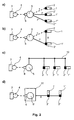
- the second figure shows some further developments, which show the possible communication paths and their configurations.
- the dashed lines represent a radio connection
- solid lines represent a cable connection.
- control unit 3 equipped with a radio module 4 is connected via radio to the radio module 6 of the relay station 5. From this go starlike connections 7, 7 'and 7 "to communication modules 2, 2', 2" of vacuum devices 1, 1 'and 1 ", which are partially designed as radio links, partly as cable connections.
- Figure c) in turn shows a relay station 5, which is connected to a bus system 10, to which the communication modules 2, 2 'and 2 "of the vacuum devices 1, 1' and 1" are connected.
- Part d) of the figure finally shows a chain-like structure of the communication paths.
- a vacuum device 11 is constructed so as to have a relay module 5 '. From this relay module, the data sent from the control device 4 to the vacuum device 1 "or vice versa is forwarded via the communication module 2 'of the vacuum device 1' .
- the chain can be constructed as shown with cable connections or alternatively with radio links according to the structure Figure part b) are combined by a connection between the vacuum device 1 "and the vacuum device 11 is provided.
Landscapes
- Engineering & Computer Science (AREA)
- Computer Networks & Wireless Communication (AREA)
- Physics & Mathematics (AREA)
- General Physics & Mathematics (AREA)
- Compressors, Vaccum Pumps And Other Relevant Systems (AREA)
- Mobile Radio Communication Systems (AREA)
- Selective Calling Equipment (AREA)
Abstract
Description
- Die Erfindung betrifft eine Anordnung mit einem Vakuumgerät nach dem Oberbegriff des ersten Anspruches.
- Vakuumanlagen sind je nach Prozess komplex und räumlich ausgedehnt. Beispielsweise befinden sich auf Glasbeschichtungsanlagen oftmals mehrere Dutzend Turbomolekularpumpen. Hinzu kommen noch weitere Vakuumgeräte wie Messröhren, Vorpumpen und dergleichen. Bei einem solchen System ist es wünschenswert, den Status von einzelnen Vakuumgeräten oder von Gruppen derselben abfragen zu können. Mit zunehmender Verbreitung von transportablen Geräten wie beispielsweise tragbaren Computern und sogenannten "Personal Digital Assistants" (PDAs), welche mit Funkkommunikationsmitteln ausgestattet sind, kam der Wunsch auf, diese bei Vakuumanlagen zu Kontroll- und Steuerzwecken einsetzen zu können.
- Die beiden
europäischen Offenlegungsschriften EP 1 497 558 A1 undEP 1 577 559 A1 schlagen vor, Vakuumgeräte mit Funkmodulen auszurüsten und so mit dem Kontrollgerät direkt eine Verbindung zu den einzelnen Vakuumgeräten aufbauen zu können. Bei der Umsetzung dieser beiden Ideen treten aber Problem auf. Insbesondere erweist sich die Funkverbindung als störanfällig, wenn es um längere Funkstrecken geht wie sie beispielsweise bei Glasbeschichtungsanlagen auftreten. - Aufgabe der Erfindung ist daher, eine störsichere Einbindung der Kontrollgeräte zu schaffen.
- Die Aufgabe wird gelöst durch eine Anordnung mit Vakuumgerät mit den Merkmalen des ersten Patentanspruchs.
- Die Störsicherheit wird dadurch erreicht, dass eine Relaisstation vorgesehen ist, die an Stelle der direkten Kommunikation zwischen Kontrollgerät und Vakuumgerät tritt. Es muss dann nur die kurze Entfernung zwischen Relaisstation und Kontrollgerät überbrückt werden. Für diese reicht die begrenzte Sendeleistung der Kontrollgeräte problemlos aus. Da nur mit der Relaisstation kommuniziert wird und leicht sichergestellt werden kann, dass diese alle mit ihr in Verbindung stehenden Vakuumgeräte der Anlage erreicht, ist im Gegensatz zum Stand der Technik gewährleistet, dass über das Kontrollgerät alle Vakuumgeräte der Anlage erfasst werden.
- Die abhängigen Ansprüche 2 bis 6 geben vorteilhafte Weiterbildungen der Erfindung an.
- So ist es besonderes störsicher, die Kommunikationsverbindung zwischen Relaisstation und Vakuumgeräten mit elektrischen Leitungen zu gestalten. Diese können gegen elektromagnetische Störstrahlung kostengünstig und einfach abgeschirmt werden.
- Es kann auch eine Funkverbindung zwischen Relaisstation und Vakuumgerät realisiert werden. Dies kann bei komplexen Anlagen mit schwierigen räumlichen Gegebenheiten vorteilhaft sein. Diese Variante funktioniert, weil eine Relaisstation im Gegensatz zu einem Kontrollgerät, welches mobil sein soll, mit nahezu beliebiger Funksendeleistung ausgestattet werden kann.
- Eine raumsparende Anordnung ergibt sich, wenn die Relaisstation als ein in ein Vakuumgerät integriertes Relaismodul ausgestaltet ist.
- Es ist eine günstige Weiterbildung, zwischen den Vakuumgeräten eine direkte Kommunikationsverbindung vorzusehen, so dass bei der Kommunikation der Weg über die Relaisstation eingespart werden kann.
- Eine vorteilhafte Weiterbildung zielt darauf ab, diese Kommunikationsverbindung dazu zu nutzen, eine Kommunikationskette zu bilden. Über diese kann das Kontrollgerät mit einem gewünschten Vakuumgerät kommunizieren, in dem es zunächst mit einer Relaisstation verbunden wird. Von dort erfolgt eine Weiterleitung über weitere Vakuumgeräte bis zum gewünschten Vakuumgerät. Diese Weiterbildung vereinfacht den Gesamtaufbau erheblich und ist ebenfalls störsicher. Wenn die einzelnen Vakuumgeräte über Funk miteinander kommunizieren, sind auch hier die Abstände deutlich kürzer als zwischen Kontrollgerät und Zielvakuumgerät. Dadurch ist auch hier ein störsicherer Betrieb gegeben.
- Anhand von Ausführungsbeispielen soll die Erfindung näher erläutert werden. Es zeigen:
- Fig. 1:
- Schematische Darstellung einer erfindungsgemäßen Anordnung.
- Fig. 2:
- Schematische Darstellungen a) bis d) von Weiterbildungen der Anordnung.
- In Abbildung 1 ist ein erstes Beispiel einer erfindungsgemäßen Anordnung gezeigt. An einem Rezipienten 8 ist ein Vakuumgerät 1 angeschlossen. Im gezeigten Beispiel ist es eine Vakuumpumpe 1a mit angeflanschter Steuerelektronik 1b. Diese Steuerelektronik kann wahlweise angeflanscht oder räumlich getrennt und über ein Kabel mit der Vakuumpumpe verbunden sein. Es kann sich bei dem Vakuumgerät auch um ein steuerbares Ventil, eine Messröhre oder dergleichen handeln. Das Vakuumgerät weist ein Kommunikationsmodul 2 auf, welches im gezeigten Beispiel direkt an der Steuerelektronik angeordnet ist. Es kann aber auch getrennt von diesem sein, beispielsweise in einem benachbarten Schaltschrank, und dann über ein Kabel mit dem Vakuumgerät in Verbindung stehen.
- Ein Kontrollgerät 3 dient dazu, Steuerdaten und Betriebsdaten zu senden und empfangen, das heißt eine bidirektionale Kommunikation durchzuführen. Diese Daten können visualisiert und/oder abgespeichert werden. Ebenfalls denkbar ist die Weitergabe über ein Netzwerk, beispielsweise einem Local Area Network (LAN), Wide Area Network (WAN) oder dem Internet. Das Kontrollgerät, ein handelsüblicher Laptop, ein PDA, ein sehr leistungsfähiges Mobiltelefon oder dergleichen, ist mit einem Funkmodul 4 ausgerüstet. Unter Betriebsdaten sind im hier genannten Zusammenhang insbesondere Ist-Werte zu verstehen, welche lediglich aus dem Vakuumgerät ausgelesen werden können, beispielsweise Drehzahl, Softwarestand, Temperatur, Druck, und dergleichen. Steuerdaten sind unter anderem Stellbefehle, die an das Vakuumgerät gesendet werden, beispielsweise "An/Aus", "Beschleunigen", und dergleichen.
- Erfindungsgemäß ist eine Relaisstation 5 in der Anordnung vorgesehen, welche ein Funkmodul 6 aufweist. Dieses steht mit dem Kommunikationsmodul 2 des Vakuumgeräts in Verbindung, um über diese Kommunikationsverbindung 7 Steuer- und Betriebsdaten zu senden und zu empfangen. Weiterhin steht die Relaisstation über sein Funkmodul 6 mit dem Funkmodul 4 des Kontrollgeräts 3 in Verbindung. Somit werden Daten zwischen dem Kontrollgerät und dem Vakuumgerät über die Relaisstation ausgetauscht. Die Relaisstation kann dabei entweder eine Echtzeitverbindung zwischen Vakuumgerät und Kontrollgerät gewährleisten oder einen Zwischenspeicher aufweisen, in dem die Daten ganz oder teilweise vorgehalten werden. Das Kontrollgerät wird meist nur temporär mit der Relaisstation verbunden sein, beispielsweise bei einer Routineüberprüfung der Anordnung. Es kann aber auch sinnvoll sein, über einen längeren Zeitraum ein Verbindung bestehen zu lassen, beispielsweise um statistische Daten über einen Zeitraum hinweg zu erheben.
- Die zweite Abbildung zeigt einige Weiterbildungen auf, die die möglichen Kommunikationswege und deren Ausgestaltungen aufzeigen. Die gestrichelten Linien stellen dabei eine Funkverbindung, durchgezogene Linien eine Kabelverbindung dar.
- Im Teil a) der Abbildung ist das mit einem Funkmodul 4 ausgestattete Kontrollgerät 3 über Funk mit dem Funkmodul 6 der Relaisstation 5 verbunden. Von dieser gehen sternartig Verbindungen 7, 7' und 7" zu Kommunikationsmodulen 2, 2', 2" von Vakuumgeräten 1, 1' und 1" aus, wobei diese teilweise als Funkverbindungen, teilweise als Kabelverbindungen ausgebildet sind.
- In Teil b) der Abbildung besteht neben den Verbindungen zwischen den Kommunikationsmodulen 2 und 2' zu der Relaisstation 5 auch eine Verbindung 9 zwischen den Kommunikationsmodulen untereinander.
- Abbildungsteil c) wiederum zeigt eine Relaisstation 5, die an ein Bussystem 10 angeschlossen ist, an welches die Kommunikationsmodule 2, 2' und 2" der Vakuumgeräte 1, 1' und 1" angeschlossen sind.
- Teil d) der Abbildung zeigt schließlich einen kettenartigen Aufbau der Kommunikationswege. Ein Vakuumgerät 11 ist so aufgebaut, dass es eine Relaismodul 5' aufweist. Von diesem Relaismodul aus werden die vom Kontrollgerät 4 an das Vakuumgerät 1" oder umgekehrt gesendeten Daten über das Kommunikationsmodul 2' des Vakuumgeräts 1' weitergeleitet. Die Kette kann dabei wie gezeigt mit Kabelverbindungen oder alternativ mit Funkverbindungen aufgebaut werden. Der kettenartige Aufbau kann außerdem mit dem Aufbau nach Abbildungsteil b) kombiniert werden, indem eine Verbindung zwischen dem Vakuumgerät 1" und dem Vakuumgerät 11 vorgesehen ist.
- Die als Funkverbindungen und als Kabelverbindungen ausgebildeten Kommunikationsverbindungen zwischen Relaisstation bzw. Relaismodul und den Kommunikationsmodulen 2, 2' und 2" sind hier beispielhaft gezeigt. Die Wahl der Verbindungsart erfolgt je nach Bedarf und ist nicht auf die gezeigten Varianten beschränkt. Anordnungen sind denkbar, die eine Kombination der Merkmale der in den Abbildungsteilen vorgestellten Anordnungen beinhalten.
Claims (6)
- Anordnung mit einem Vakuumgerät (1; 1', 1''), welches ein Kommunikationsmodul (2) aufweist, und mit einem Kontrollgerät (3), welches ein Funkmodul (4) aufweist, wobei Kommunikations- und Funkmodul zum Senden und Empfangen von Betriebs- und Steuerdaten eingerichtet sind, dadurch gekennzeichnet, dass die Anordnung eine Relaisstation (5) mit einem Funkmodul (6) aufweist, womit sie drahtlos bidirektional mit dem Kontrollgerät kommuniziert, wobei zwischen Relaisstation und Kommunikationsmodul des Vakuumgeräts eine Kommunikationsverbindung (7;7',7") besteht.
- Anordnung nach Anspruch 1, dadurch gekennzeichnet, dass die Kommunikationsverbindung (7;7',7") eine elektrische Leitung umfasst.
- Anordnung nach Anspruch 1, dadurch gekennzeichnet, dass die Kommunikationsverbindung (7;7',7") eine Funkverbindung umfasst.
- Anordnung nach einem der vorhergehenden Ansprüche, dadurch gekennzeichnet, dass ein Kommunikationsmodul (2) eines Vakuumgeräts (11) ein Relaismodul (5') umfasst.
- Anordnung nach einem der vorhergehenden Ansprüche, dadurch gekennzeichnet, dass sie ein erstes (1) und ein zweites (1') Vakuumgerät aufweist, wobei diese eine Kommunikationsverbindung (9) untereinander aufweisen.
- Anordnung nach Anspruch 5, dadurch gekennzeichnet, dass über die Kommunikationsverbindung (9) eine Verbindung zwischen Kontrollgerät (3) und zweitem Vakuumgerät (1') besteht.
Applications Claiming Priority (1)
| Application Number | Priority Date | Filing Date | Title |
|---|---|---|---|
| DE200610045024 DE102006045024A1 (de) | 2006-09-23 | 2006-09-23 | Anordnung mit Vakuumgerät |
Publications (2)
| Publication Number | Publication Date |
|---|---|
| EP1903529A1 true EP1903529A1 (de) | 2008-03-26 |
| EP1903529B1 EP1903529B1 (de) | 2017-04-12 |
Family
ID=38814641
Family Applications (1)
| Application Number | Title | Priority Date | Filing Date |
|---|---|---|---|
| EP07017435.4A Active EP1903529B1 (de) | 2006-09-23 | 2007-09-06 | Anordnung mit einem Vakuumgerät |
Country Status (2)
| Country | Link |
|---|---|
| EP (1) | EP1903529B1 (de) |
| DE (1) | DE102006045024A1 (de) |
Cited By (1)
| Publication number | Priority date | Publication date | Assignee | Title |
|---|---|---|---|---|
| EP3951738A3 (de) * | 2021-12-13 | 2022-07-06 | Pfeiffer Vacuum Technology AG | Vorrichtung und verfahren zur kommunikation mit einem vakuumgerät |
Families Citing this family (1)
| Publication number | Priority date | Publication date | Assignee | Title |
|---|---|---|---|---|
| DE102013106474A1 (de) | 2013-06-20 | 2014-12-24 | Pfeiffer Vacuum Gmbh | Anordnung mit einem Vakuumgerät sowie Verfahren zur Erfassung von in einer Kommunikationsleitung zwischen einem Vakuumgerät und einer zentralen Steuereinrichtung kommunizierten Daten |
Citations (3)
| Publication number | Priority date | Publication date | Assignee | Title |
|---|---|---|---|---|
| GB1335942A (en) * | 1971-04-29 | 1973-10-31 | Silvani Di Ing Cesare Khouzam | Remote control systems for fire fighting plants |
| US20030210154A1 (en) * | 2002-03-06 | 2003-11-13 | Wolfgang Bredow | Process for the control of industrial or construction machinery |
| EP1424159A1 (de) * | 2002-11-27 | 2004-06-02 | Crc-Evans Pipeline International, Inc. | Schnurlose Innenzentrierung zum Schweissen von Pipelines |
Family Cites Families (7)
| Publication number | Priority date | Publication date | Assignee | Title |
|---|---|---|---|---|
| US5793963A (en) * | 1994-10-24 | 1998-08-11 | Fisher Rosemount Systems, Inc. | Apparatus for providing non-redundant secondary access to field devices in a distributed control system |
| DE20206267U1 (de) * | 2002-04-20 | 2003-08-28 | Leybold Vakuum GmbH, 50968 Köln | Vakuumpumpe |
| DE602004005154T2 (de) * | 2004-03-15 | 2007-11-08 | Varian S.P.A., Leini | Vakuumpumpenanlage |
| JP2006039892A (ja) * | 2004-07-27 | 2006-02-09 | Yokogawa Electric Corp | フィールド機器 |
| DE102004047853A1 (de) * | 2004-10-01 | 2006-04-20 | Festo Ag & Co. | Steuereinrichtung für wenigstens ein Saugelement |
| DE102004062157B4 (de) * | 2004-12-20 | 2007-12-20 | EMH Elektrizitätszähler GmbH & Co. KG | Vorrichtung zum Erfassen von Zählerständen |
| DE102005008488B4 (de) * | 2005-02-24 | 2011-08-18 | VEGA Grieshaber KG, 77709 | Datenübertragungssystem zur drahtlosen Kommunikation |
-
2006
- 2006-09-23 DE DE200610045024 patent/DE102006045024A1/de not_active Ceased
-
2007
- 2007-09-06 EP EP07017435.4A patent/EP1903529B1/de active Active
Patent Citations (3)
| Publication number | Priority date | Publication date | Assignee | Title |
|---|---|---|---|---|
| GB1335942A (en) * | 1971-04-29 | 1973-10-31 | Silvani Di Ing Cesare Khouzam | Remote control systems for fire fighting plants |
| US20030210154A1 (en) * | 2002-03-06 | 2003-11-13 | Wolfgang Bredow | Process for the control of industrial or construction machinery |
| EP1424159A1 (de) * | 2002-11-27 | 2004-06-02 | Crc-Evans Pipeline International, Inc. | Schnurlose Innenzentrierung zum Schweissen von Pipelines |
Cited By (1)
| Publication number | Priority date | Publication date | Assignee | Title |
|---|---|---|---|---|
| EP3951738A3 (de) * | 2021-12-13 | 2022-07-06 | Pfeiffer Vacuum Technology AG | Vorrichtung und verfahren zur kommunikation mit einem vakuumgerät |
Also Published As
| Publication number | Publication date |
|---|---|
| EP1903529B1 (de) | 2017-04-12 |
| DE102006045024A1 (de) | 2008-03-27 |
Similar Documents
| Publication | Publication Date | Title |
|---|---|---|
| EP2424745B1 (de) | Verfahren und anordnung zur datenkommunikation zwischen einem diensteanbieter und einem fahrzeug | |
| EP2984530B1 (de) | Messumformerspeisegerät mit abschaltbarer funkschnittstelle | |
| DE19942509A1 (de) | Verfahren und Vorrichtung zur Versorgung von elektrischen Verbrauchern in oder an einer pneumatischen Vorrichtung mit elektrischer Versorgungsenergie | |
| EP1427086B2 (de) | Elektrisches Gerät und Verfahren zum Betreiben eines elektrischen Geräts | |
| EP1442338A1 (de) | Funkmodul für feldgeräte | |
| DE102017213589A1 (de) | Schmiersystem mit einem Signalübertragungselement | |
| EP1497558B1 (de) | Vakuumpumpe | |
| WO2017060018A1 (de) | Modular aufgebautes feldgerät mit einem anzeige-/bediengerät, das ein funkmodul und eine interne energieversorgung enthält | |
| EP1145208B1 (de) | Verfahren und vorrichtung zur übertragung von steuer- und/oder sensorsignalen | |
| DE102017123821A1 (de) | Anzeige- und/oder Bedienmodul | |
| EP1903529B1 (de) | Anordnung mit einem Vakuumgerät | |
| WO2007082773A1 (de) | Drahtlose feldbus verwaltung | |
| DE102012109227A1 (de) | Anordnung, umfassend zumindest ein Feldgerät, zumindest eine diesem zugeordnete Sensor- oder Signalerfassungseinheit und zumindest einen Funktionsblock | |
| DE102017213365A1 (de) | Kommunikationsvorrichtung, System und Verfahren | |
| EP2397381B1 (de) | Automatische Türanlage | |
| EP3438518B1 (de) | Schmiersystem mit einem energieerzeugungselement | |
| DE19928984A1 (de) | Bussystem mit abgesicherten Ausgängen | |
| DE102005040932A1 (de) | Feldbusteilnehmer | |
| DE102006018174B4 (de) | Messwerterfassungseinrichtung | |
| DE102010062670B4 (de) | Wartungseinheit für ein ASI-Bussystem sowie ASI-Bussystem | |
| WO2009030243A1 (de) | Grund- oder erweiterungsmodul für ein modulares schaltgerät, modulares schaltgerät und vorrichtung zum projektieren oder konfigurieren eines modularen schaltgeräts | |
| EP1281656A1 (de) | System zur Fernwartung eines Krans und Vorrichtung hierfür | |
| EP1972107B1 (de) | Schutz- oder leittechnikgerät | |
| DE2826063C2 (de) | ||
| DE102005039917A1 (de) | Anzeigevorrichtung, insbesondere in einem Kraftfahrzeug |
Legal Events
| Date | Code | Title | Description |
|---|---|---|---|
| PUAI | Public reference made under article 153(3) epc to a published international application that has entered the european phase |
Free format text: ORIGINAL CODE: 0009012 |
|
| AK | Designated contracting states |
Kind code of ref document: A1 Designated state(s): AT BE BG CH CY CZ DE DK EE ES FI FR GB GR HU IE IS IT LI LT LU LV MC MT NL PL PT RO SE SI SK TR |
|
| AX | Request for extension of the european patent |
Extension state: AL BA HR MK YU |
|
| 17P | Request for examination filed |
Effective date: 20080808 |
|
| 17Q | First examination report despatched |
Effective date: 20080926 |
|
| AKX | Designation fees paid |
Designated state(s): AT BE BG CH CY CZ DE DK EE ES FI FR GB GR HU IE IS IT LI LT LU LV MC MT NL PL PT RO SE SI SK TR |
|
| GRAP | Despatch of communication of intention to grant a patent |
Free format text: ORIGINAL CODE: EPIDOSNIGR1 |
|
| INTG | Intention to grant announced |
Effective date: 20161104 |
|
| RAP1 | Party data changed (applicant data changed or rights of an application transferred) |
Owner name: PFEIFFER VACUUM GMBH |
|
| GRAS | Grant fee paid |
Free format text: ORIGINAL CODE: EPIDOSNIGR3 |
|
| GRAA | (expected) grant |
Free format text: ORIGINAL CODE: 0009210 |
|
| AK | Designated contracting states |
Kind code of ref document: B1 Designated state(s): AT BE BG CH CY CZ DE DK EE ES FI FR GB GR HU IE IS IT LI LT LU LV MC MT NL PL PT RO SE SI SK TR |
|
| REG | Reference to a national code |
Ref country code: GB Ref legal event code: FG4D Free format text: NOT ENGLISH |
|
| REG | Reference to a national code |
Ref country code: CH Ref legal event code: EP |
|
| REG | Reference to a national code |
Ref country code: IE Ref legal event code: FG4D Free format text: LANGUAGE OF EP DOCUMENT: GERMAN |
|
| REG | Reference to a national code |
Ref country code: AT Ref legal event code: REF Ref document number: 884598 Country of ref document: AT Kind code of ref document: T Effective date: 20170515 |
|
| REG | Reference to a national code |
Ref country code: DE Ref legal event code: R096 Ref document number: 502007015570 Country of ref document: DE |
|
| REG | Reference to a national code |
Ref country code: NL Ref legal event code: MP Effective date: 20170412 |
|
| REG | Reference to a national code |
Ref country code: LT Ref legal event code: MG4D |
|
| PG25 | Lapsed in a contracting state [announced via postgrant information from national office to epo] |
Ref country code: NL Free format text: LAPSE BECAUSE OF FAILURE TO SUBMIT A TRANSLATION OF THE DESCRIPTION OR TO PAY THE FEE WITHIN THE PRESCRIBED TIME-LIMIT Effective date: 20170412 |
|
| PG25 | Lapsed in a contracting state [announced via postgrant information from national office to epo] |
Ref country code: GR Free format text: LAPSE BECAUSE OF FAILURE TO SUBMIT A TRANSLATION OF THE DESCRIPTION OR TO PAY THE FEE WITHIN THE PRESCRIBED TIME-LIMIT Effective date: 20170713 Ref country code: LT Free format text: LAPSE BECAUSE OF FAILURE TO SUBMIT A TRANSLATION OF THE DESCRIPTION OR TO PAY THE FEE WITHIN THE PRESCRIBED TIME-LIMIT Effective date: 20170412 Ref country code: FI Free format text: LAPSE BECAUSE OF FAILURE TO SUBMIT A TRANSLATION OF THE DESCRIPTION OR TO PAY THE FEE WITHIN THE PRESCRIBED TIME-LIMIT Effective date: 20170412 Ref country code: ES Free format text: LAPSE BECAUSE OF FAILURE TO SUBMIT A TRANSLATION OF THE DESCRIPTION OR TO PAY THE FEE WITHIN THE PRESCRIBED TIME-LIMIT Effective date: 20170412 |
|
| PG25 | Lapsed in a contracting state [announced via postgrant information from national office to epo] |
Ref country code: PL Free format text: LAPSE BECAUSE OF FAILURE TO SUBMIT A TRANSLATION OF THE DESCRIPTION OR TO PAY THE FEE WITHIN THE PRESCRIBED TIME-LIMIT Effective date: 20170412 Ref country code: IS Free format text: LAPSE BECAUSE OF FAILURE TO SUBMIT A TRANSLATION OF THE DESCRIPTION OR TO PAY THE FEE WITHIN THE PRESCRIBED TIME-LIMIT Effective date: 20170812 Ref country code: SE Free format text: LAPSE BECAUSE OF FAILURE TO SUBMIT A TRANSLATION OF THE DESCRIPTION OR TO PAY THE FEE WITHIN THE PRESCRIBED TIME-LIMIT Effective date: 20170412 Ref country code: LV Free format text: LAPSE BECAUSE OF FAILURE TO SUBMIT A TRANSLATION OF THE DESCRIPTION OR TO PAY THE FEE WITHIN THE PRESCRIBED TIME-LIMIT Effective date: 20170412 Ref country code: BG Free format text: LAPSE BECAUSE OF FAILURE TO SUBMIT A TRANSLATION OF THE DESCRIPTION OR TO PAY THE FEE WITHIN THE PRESCRIBED TIME-LIMIT Effective date: 20170712 |
|
| REG | Reference to a national code |
Ref country code: DE Ref legal event code: R097 Ref document number: 502007015570 Country of ref document: DE |
|
| PG25 | Lapsed in a contracting state [announced via postgrant information from national office to epo] |
Ref country code: EE Free format text: LAPSE BECAUSE OF FAILURE TO SUBMIT A TRANSLATION OF THE DESCRIPTION OR TO PAY THE FEE WITHIN THE PRESCRIBED TIME-LIMIT Effective date: 20170412 Ref country code: DK Free format text: LAPSE BECAUSE OF FAILURE TO SUBMIT A TRANSLATION OF THE DESCRIPTION OR TO PAY THE FEE WITHIN THE PRESCRIBED TIME-LIMIT Effective date: 20170412 Ref country code: RO Free format text: LAPSE BECAUSE OF FAILURE TO SUBMIT A TRANSLATION OF THE DESCRIPTION OR TO PAY THE FEE WITHIN THE PRESCRIBED TIME-LIMIT Effective date: 20170412 Ref country code: SK Free format text: LAPSE BECAUSE OF FAILURE TO SUBMIT A TRANSLATION OF THE DESCRIPTION OR TO PAY THE FEE WITHIN THE PRESCRIBED TIME-LIMIT Effective date: 20170412 |
|
| PLBE | No opposition filed within time limit |
Free format text: ORIGINAL CODE: 0009261 |
|
| STAA | Information on the status of an ep patent application or granted ep patent |
Free format text: STATUS: NO OPPOSITION FILED WITHIN TIME LIMIT |
|
| 26N | No opposition filed |
Effective date: 20180115 |
|
| REG | Reference to a national code |
Ref country code: CH Ref legal event code: PL |
|
| PG25 | Lapsed in a contracting state [announced via postgrant information from national office to epo] |
Ref country code: MC Free format text: LAPSE BECAUSE OF FAILURE TO SUBMIT A TRANSLATION OF THE DESCRIPTION OR TO PAY THE FEE WITHIN THE PRESCRIBED TIME-LIMIT Effective date: 20170412 Ref country code: SI Free format text: LAPSE BECAUSE OF FAILURE TO SUBMIT A TRANSLATION OF THE DESCRIPTION OR TO PAY THE FEE WITHIN THE PRESCRIBED TIME-LIMIT Effective date: 20170412 |
|
| REG | Reference to a national code |
Ref country code: IE Ref legal event code: MM4A |
|
| REG | Reference to a national code |
Ref country code: BE Ref legal event code: MM Effective date: 20170930 |
|
| PG25 | Lapsed in a contracting state [announced via postgrant information from national office to epo] |
Ref country code: LU Free format text: LAPSE BECAUSE OF NON-PAYMENT OF DUE FEES Effective date: 20170906 |
|
| REG | Reference to a national code |
Ref country code: FR Ref legal event code: ST Effective date: 20180531 |
|
| PG25 | Lapsed in a contracting state [announced via postgrant information from national office to epo] |
Ref country code: IE Free format text: LAPSE BECAUSE OF NON-PAYMENT OF DUE FEES Effective date: 20170906 Ref country code: CH Free format text: LAPSE BECAUSE OF NON-PAYMENT OF DUE FEES Effective date: 20170930 Ref country code: LI Free format text: LAPSE BECAUSE OF NON-PAYMENT OF DUE FEES Effective date: 20170930 |
|
| PG25 | Lapsed in a contracting state [announced via postgrant information from national office to epo] |
Ref country code: BE Free format text: LAPSE BECAUSE OF NON-PAYMENT OF DUE FEES Effective date: 20170930 Ref country code: FR Free format text: LAPSE BECAUSE OF NON-PAYMENT OF DUE FEES Effective date: 20171002 |
|
| PG25 | Lapsed in a contracting state [announced via postgrant information from national office to epo] |
Ref country code: MT Free format text: LAPSE BECAUSE OF FAILURE TO SUBMIT A TRANSLATION OF THE DESCRIPTION OR TO PAY THE FEE WITHIN THE PRESCRIBED TIME-LIMIT Effective date: 20170412 |
|
| REG | Reference to a national code |
Ref country code: AT Ref legal event code: MM01 Ref document number: 884598 Country of ref document: AT Kind code of ref document: T Effective date: 20170906 |
|
| PG25 | Lapsed in a contracting state [announced via postgrant information from national office to epo] |
Ref country code: AT Free format text: LAPSE BECAUSE OF NON-PAYMENT OF DUE FEES Effective date: 20170906 |
|
| PG25 | Lapsed in a contracting state [announced via postgrant information from national office to epo] |
Ref country code: HU Free format text: LAPSE BECAUSE OF FAILURE TO SUBMIT A TRANSLATION OF THE DESCRIPTION OR TO PAY THE FEE WITHIN THE PRESCRIBED TIME-LIMIT; INVALID AB INITIO Effective date: 20070906 |
|
| PG25 | Lapsed in a contracting state [announced via postgrant information from national office to epo] |
Ref country code: CY Free format text: LAPSE BECAUSE OF NON-PAYMENT OF DUE FEES Effective date: 20170412 |
|
| PG25 | Lapsed in a contracting state [announced via postgrant information from national office to epo] |
Ref country code: TR Free format text: LAPSE BECAUSE OF FAILURE TO SUBMIT A TRANSLATION OF THE DESCRIPTION OR TO PAY THE FEE WITHIN THE PRESCRIBED TIME-LIMIT Effective date: 20170412 |
|
| PG25 | Lapsed in a contracting state [announced via postgrant information from national office to epo] |
Ref country code: PT Free format text: LAPSE BECAUSE OF FAILURE TO SUBMIT A TRANSLATION OF THE DESCRIPTION OR TO PAY THE FEE WITHIN THE PRESCRIBED TIME-LIMIT Effective date: 20170412 |
|
| PGFP | Annual fee paid to national office [announced via postgrant information from national office to epo] |
Ref country code: IT Payment date: 20230726 Year of fee payment: 17 Ref country code: GB Payment date: 20230725 Year of fee payment: 17 |
|
| PGFP | Annual fee paid to national office [announced via postgrant information from national office to epo] |
Ref country code: DE Payment date: 20230810 Year of fee payment: 17 |
|
| PGFP | Annual fee paid to national office [announced via postgrant information from national office to epo] |
Ref country code: CZ Payment date: 20240618 Year of fee payment: 18 |