EP1903437A2 - Update data transmission method, firmware writing system, and update data transmission program - Google Patents
Update data transmission method, firmware writing system, and update data transmission program Download PDFInfo
- Publication number
- EP1903437A2 EP1903437A2 EP07014244A EP07014244A EP1903437A2 EP 1903437 A2 EP1903437 A2 EP 1903437A2 EP 07014244 A EP07014244 A EP 07014244A EP 07014244 A EP07014244 A EP 07014244A EP 1903437 A2 EP1903437 A2 EP 1903437A2
- Authority
- EP
- European Patent Office
- Prior art keywords
- data
- format
- records
- object data
- block
- Prior art date
- Legal status (The legal status is an assumption and is not a legal conclusion. Google has not performed a legal analysis and makes no representation as to the accuracy of the status listed.)
- Withdrawn
Links
Images



Classifications
-
- G—PHYSICS
- G06—COMPUTING OR CALCULATING; COUNTING
- G06F—ELECTRIC DIGITAL DATA PROCESSING
- G06F8/00—Arrangements for software engineering
- G06F8/60—Software deployment
- G06F8/65—Updates
Definitions
- the present invention relates to an update data transmission method for sending data for updating the firmware (program) of a peripheral device from a computer to the peripheral device, and to an update data transmission program for causing a computer to execute the update data transmission method.
- the invention also relates to a firmware writing system including a computer that sends firmware update data for a peripheral device to the peripheral device, and the peripheral device that rewrites its firmware based on firmware update data received from the computer.
- JP-A-2005-63050 teaches a method of updating firmware by receiving data for updating a control program from an external device, and using a writing program stored in a second storage area in flash memory to update the control program stored in a first storage area in flash memory with the received update data. If the peripheral device is connected to a network, the firmware update data can be received from the computer over the network to update the firmware.
- the computer sends the firmware update data for the peripheral device to the peripheral device using a known format such as the Motorola (R) S3 format.
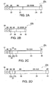
- the Motorola S3 format writes the compiled source code written in a programming language in a hexadecimal text file, and includes a management data part containing the data storage address, for example, and the object data (see FIG. 2A).
- the Motorola S3 format uses two letters to express one byte of data.
- the peripheral device converts the received text data from the Motorola S3 format (referred to below as the S3 ASCII format) to binary data, and writes the binary data to flash memory.
- the update data is thus written in a prescribed format such as the Motorola S3 format, and is sent and received in record (packet) units.
- JP-A-2000-134230 teaches a method of generating the transmission packets by segmenting the available storage area in RAM, for example, into a header area where the header is stored and a data area where the data is stored, and linking the header stored in the header area to the data stored in the data area by a hardware operation that outputs the transmission packets.
- Increased functionality in the peripheral devices has also increased the size of the firmware, which has increased the number of records (the number of data units) that are sent and received when the firmware is updated.
- Sending and receiving large amounts of update data is not particularly a problem when a high speed communication interface such as USB, a parallel interface, or Ethernet (R) connects the computer and the peripheral device, but sending the update data can take a long time if an RS-232C or other low speed communication interface is used.
- the peripheral device usually cannot be used while the firmware update data is being received, and completing the data transmission in the shortest possible time is therefore particularly desirable in any situation where the peripheral devices are normally used 24 hours a day.
- JP-A-H11-212908 addresses this problem by teaching an interface box for temporarily storing in memory data received from a computer using an RS-232C (9600 bps, for example) interface, and then transferring the data from memory to a mobile information device using a faster (such as 50,000 bps) serial or parallel interface.
- the mobile information device can thus reduce the time that is required for data communication.
- the communication time can also be shortened by reducing the amount of transferred data.
- JP-AH06-242894 teaches a method of counting the number of consecutive values representing a blank character (0x20) in the print data to be sent to the printer, and if this number is greater than or equal to a prescribed reference value, sending control data instead of the consecutive blank characters to move the printing position (print head) of the printer in one step a distance equal to the number of consecutive blanks.
- JP-A-H11-212908 A problem with the technology taught in JP-A-H11-212908 , however, is that in addition to requiring an interface box, the peripheral device must also be made compatible with the interface box, and the interface box is thus lacking in general applicability. Furthermore, because the data transfer rate between the computer and the interface box is the bottleneck, the update data communication time is not shortened from the perspective of the overall system.
- Concatenating sets of object data of plural source records to one set of object data of a target record reduces the number of target records (transmission data units) as compared to those of the source records, and thus also reduces the amount of management data required for the records. This also reduces the total amount of transmission data and thereby shortens the data communication time. Furthermore, by applying an upper limit to the length of the concatenated object data, communication errors can be detected and data transmission can be retried more quickly, and unnecessary data communication can be avoided. The total amount of data to be transmitted is further reduced by deleting consecutive blocks of blank data exceeding the length of the management data in the target records.
- blade refers to a particular data value namely that one that is used for initializing and erasing flash memory.
- a particular value i.e., a "blank”
- ASCII value 0xFF is used as this particular value.
- bladenk represents the same value as that used for initializing and erasing the non-volatile memory that stores the firmware data in the peripheral device, e.g., a printer.
- a first format (format of the source records) is an ASCII code format
- a second format (format of the target records) is a binary format.
- the total amount of transmission data can be approximately halved by converting ASCII to binary, and the data communication time can therefore also be approximately halved.
- the binary conversion does not need to be done on the peripheral device side as in the related art, and the processor load of the firmware updating process is reduced on the peripheral device side. Because the CPU used in the peripheral device is generally less powerful than the CPU used by the computer, reducing the processor load om the peripheral device improves the performance of the firmware updating process of the overall system including both the host computer and the peripheral device.
- the upper limit of the length (also referred to as block data length) of the concatenated object data (also referred to as object data block) is less than or equal to the length of the data writing unit of the flash memory that stores the peripheral device firmware. If the block data length is greater than the length of the data writing unit (the sector capacity), the peripheral device may need to segment the object data into the length of the data writing unit. This increases the processor load for the peripheral device and thus reduces the performance of the firmware writing process for the overall system.
- the upper limit of the block data length is set according to the type of interface to which the peripheral device is connected. Yet further preferably, the communication speed with the peripheral device is measured and the upper limit is set according to the measured communication speed.
- a firmware writing system 1 includes a host computer 11, a plurality of servers 12a, 12b, 12c, and a plurality of peripheral devices, printers 13a1, 13a2, 13b, 13c, and 13d for example.
- the host computer 11 and the servers 12a to 12c are connected over a network 14.
- Printers 13a1 and 13a2 are connected to the server 12a by interfaces 15a1 and 15a2, respectively.
- the printer 13b is connected to server 12b by an interface 15b
- the printer 13c is connected to the server 12c by an interface 15c.
- the printer 13d is connected through the interface 15d to the network 14, and can be controlled by the host computer 11 and the servers 12a to 12c that are also connected to the network 14.
- the servers 12a to 12c may be common personal computers or dedicated information processing devices such as a POS terminals.
- the network 14 can be a local area network (LAN) such as an Ethernet network, or a wide-area network (WAN) such as a dedicated line, the Internet, a virtual private network (VPN). If the network 14 is a WAN, the host computer 11 can instruct the remote servers 12a to 12c to update the firmware of the connected printers 13a1 to 13c. The host computer 11 can also instruct a printer 13d connected directly to the network 14 to update the firmware. A single host computer 11 can thus control updating the firmware in a plurality of remote printers 13a1 to 13d.
- LAN local area network
- WAN wide-area network
- VPN virtual private network
- the interfaces 15a1 to 15c can be serial interfaces such as RS-232C (14.4 kbps maximum data transfer rate) or USB (60 Mbps maximum data transfer rate with USB 2.0) interfaces, or parallel interfaces such as SCSI (320 Mbps maximum data transfer rate).
- serial interfaces such as RS-232C (14.4 kbps maximum data transfer rate) or USB (60 Mbps maximum data transfer rate with USB 2.0) interfaces
- parallel interfaces such as SCSI (320 Mbps maximum data transfer rate).
- the servers 12a to 12c can be connected to the host computer 11 over the network 14 using different data transfer rates.
- the printers 13a1 and 13a2 can also be connected to the server 12a at different data transfer rates.
- the host computer 11 in this firmware writing system 1 sends the firmware update data to the printers 13a1 to 13d, and the individual printers update their own firmware accordingly.
- the servers 12a to 12c can send the firmware update data to the connected printers 13a1 to 13c, and the individual printers update their own firmware accordingly.
- the invention is further described below using the server 12b (computer) and the printer 13b (peripheral device) as example of a firmware writing system according to the present invention to describe the process for updating the firmware in the printer 13b.
- the firmware of printer 13b is written in a programming language and the source code is compiled and supplied to the server 12b in the Motorola S3 format, which is a hexadecimal text format.
- the firmware source code could be supplied to the server 12b, and the server 12b could convert the source code to the Motorola S3 format.
- one record 20a (data unit) in the Motorola S3 format includes a type field 21, a data length field 22, an address field 23, a data field 24, and a checksum field 25.
- the type field 21 is a value denoting the Motorola S format type (record type), and is 2 bytes long. This aspect of the invention uses the S3 format, but other Motorola S formats include the S1 and S2 formats. Types S7 to S9 are also defined as type S1 to S3 terminators.
- the data length field 22 is a 2-byte value indicating the amount of data that follows, that is, the record length.
- the address field 23 is an 8-byte value denoting the address where the first byte of the data packed in the data field 24 is stored in the flash memory 132 of the printer 13b.
- the data field 24 is from 2 to 500 bytes long, and contains the actual data (object data) to be written to the flash memory 132 of the printer 13b.
- the checksum field 25 contains a 2 byte checksum that is calculated from the byte values in the data length field 22, the address field 23, and the data field 24.
- management data The data other than the object data in the data field 24, that is, the record type, record length, address, and checksum values are referred to below as "management data", and the object data and the management data together constitute one record (data unit).
- the server 12b has a control unit (CPU) 111, a storage unit 112, a communication interface 113, an input unit 114, and a display unit 115 connected to each other over a bus 116.
- CPU control unit
- storage unit 112 storage unit
- communication interface 113 communication interface
- input unit 114 input unit
- display unit 115 display unit
- the control unit 111 reads programs stored in the storage unit 112 as needed to control the server 12b.
- the control unit 111 includes a data reading unit 111 a, a blank data detection unit 111 b, a data length comparator 111c, a data appending unit 111d, a record (data unit) generator 111e, and a data conversion unit 111 f.
- the data reading unit 111 a sequentially reads each record (source record) of the firmware update data (Motorola S3 format) for the printer 13b from the storage unit 112 in response to a firmware updating command from the host computer 11 or from the operator of the server 12b.
- the update data can be provided by the operator on the server 12b, or the update data can be received from the host computer 11 over the network 14.
- the blank data detection unit 111b determines if a block of consecutive blanks (0xFF) is contained in the object data of the source record read by the data reading unit 111a whose length is equal to or longer than a predetermined number.
- the data appending unit 111 d forms object data blocks by sequentially appending object data of the currently processed source record to those of one or more previously processed source records until a predetermined maximum allowable data length is reached.
- the data length comparator 111c compares the actual length (block data length) of the currently formed object data block with the predetermined maximum allowable value of this data length. As soon as one object data block has reached its maximum allowable block data length any remaining object data of the currently processed source record form the begin of the next object data block to which object data of subsequent source records will then be appended.
- the blank data detection unit 111b detects such block of consecutive blanks whose length is no less than said predetermined number
- the data appending unit 111d appends the object data of a first segment, namely that preceding the detected block, until the maximum allowable data length of the currently formed object data block is reached, whereas a new object data block is started with a second segment including the object data that follow the detected block.
- the detected block of blanks is deleted, i.e., these blanks are not appended to any object data block.
- the blank data can be deleted because erasing the flash memory 132 stores blanks (0xFF).
- the record generator 111 e adds management data to each thus formed object data block the added management data corresponding to the respective object data block formed by the data appending unit 111d.
- Each object data block with the corresponding management data added to it is output as a new record 20c (first alternative) or 20d (second alternative). More specifically, the record generator 111 e determines the record length based on the data length of the object data block, specifies the address where the first byte of the object data block is stored, and calculates a checksum.
- the data conversion unit 111f converts the update data composed of the record 20a read by the data reading unit 111a, from the ASCII format to a binary format record 20b shown in Fig. 2B.
- the record generator 111e generates new records as records 20c from records 20b as source records.
- the record generator 111e generates new records as records 20d from records 20a as source records and the data conversion unit 111f converts the records 20d from the ASCII format to a binary format.
- the storage unit 112 functions as working memory for the control unit 111 and as the update data storage area, and can include local memory and cache memory.
- the storage unit 112 may be one that allows reading and writing data electrically, magnetically, or optically, and may be a semiconductor storage device (hard disk and memory), magnetic tape, a floppy disk, a magnetooptical disc, or an optical disc, for example.
- the communication interface 113 could be a serial interface or a parallel interface for connecting the printer 13b.
- the communication interface 113 also includes an Ethernet adapter or modem for connecting to the host computer 11 over the network 14.
- the input unit 114 is used for operator input, and includes a keyboard and a pointing device.
- the display unit 115 can be an LCD panel or other type of monitor for displaying a screen for getting data input from the operator, and displaying the results of the operations of server 12b and progress reports.
- the printer 13b includes primarily a control unit (CPU) 131, a flash memory 132, a RAM 133, a communication interface 134, operating buttons 135, a display unit 136, and a printer unit 137 connected to a common bus 138.
- CPU control unit
- flash memory 132
- RAM random access memory
- communication interface 134
- operating buttons 135 a display unit 136
- printer unit 137 connected to a common bus 138.
- the control unit 131 reads and executes programs and firmware from flash memory 132 as needed and thus controls the printer 13b.
- the control unit 131 includes a firmware writing unit 131a that reads and executes a firmware writing program to update the firmware in response to a command from the server 12b or when firmware update data is received.
- the flash memory 132 is a nonvolatile memory that allows erasing and overwriting data in batches in units of a sector (such as 64 KB units).
- the RAM 133 functions as local memory and cache memory used by the control unit 131 when running programs.
- the communication interface 134 is a RS-232C, USB, or other serial interface, or a SCSI or other parallel interface for connecting to the server 12b.
- the operating buttons 135 are for getting user input from the operator.
- the display unit 136 can be an LCD or LED panel or other type of monitor for displaying a screen for getting data input from the operator, and displaying the results of operations of printer 13b, progress reports, and status reports.
- the printer unit 137 includes a print head and paper transportation mechanism, and prints on the recording paper as controlled by the control unit 131.
- the server 12b first executes a preprocessing step (S101) before starting the firmware update data transmission process. This includes, for example, the control unit 111 stopping a resident print spooler, if any.
- the data reading unit 111a then sequentially reads the firmware update data for the printer 13b in the Motorola S3 format, one record at a time, from the storage unit 112 (S102).
- S102 the firmware update data for the printer 13b in the Motorola S3 format, one record at a time
- S103 returns Yes
- the data reading unit 111a converts the records from the read S3 format to a binary format as shown in FIG. 2B (S104).
- ASCII codes 0x30 ("0") to 0x39 ("9") and 0x41 ("A") to 0x46 (“F") are respectively converted to 0x0 to 0x9 and 0xA to 0xF by binary conversion. Converting from ASCII to binary code thus reduces the amount of data by half.
- the data in fields 22 to 24 (but not the type field 21) is binary converted and the checksum is calculated based on the binary values for fields 22 to 24.
- the binary record 20b includes 8 bytes of management data including a 2-byte type field 26, a 1-byte data length field 27, a 4-byte address field 28, and a 1-byte checksum field 30, and a maximum 250-byte data field 29.
- the data format shown in FIG. 2A is referred to below as the S3 ASCII format, and the format shown in FIG. 2B is referred to as the S3 binary format.
- the blank data detection unit 111 b detects for each record if the object data in the data field 29 contains a block of 10 or more consecutive blank bytes (bytes of value 0xFF) (S105). Detecting a block of consecutive blanks is not limited to each record, and the presence of consecutive blanks in the object data of consecutive records is preferably detected. For example, if the last five bytes in the object data of one record are blanks and the first five bytes in the object data of the next record are also blanks, a block of ten or more consecutive blanks is preferably detected.
- the data length comparator 111c determines if the block data length, i.e., the data length of the curretnly formed object data block, exceeds the maximum block data length (2 KB in this embodiment of the invention) (S106). More specifically, the data length comparator 111c determines if the lengths of the object data read to that point exceeds the maximum block data length. If the block data length does not exceed its maximum allowable value of 2 KB in this example (S106 returns No), the data appending unit 111d appends the data that was just read (S107) to those of previously read records in the currently formed object data block.
- the maximum block data length was experimentally determined by measuring the time required to transmit data of a predetermined size using the record length as a parameter to find the effective, efficient record length affording a short transmission time and a record length that is not too long. Simply increasing the record length does not effectively shorten the transmission time, and is conversely inefficient because more time is required for error checking during communication.
- the record length is also preferably less than or equal to the sector size of the flash memory 132 used in the printer 13b. If an RS-232C or USB serial interface were used as the communication interfaces 113 and 134, for example, tests showed that the maximum block data length is preferably about 2 KB.
- the predetermined maximum block data lengths are preferably stored in a lookup table on the server 12b for each interface or data communication rate so that the maximum block data length can be selected as needed.
- the communication speed between the server 12b and the printer 13b can be measured, and the maximum block data length can be selected from the lookup table based on the measured speed.
- the communication speed can be measured by, for example, sending a known amount of data from the server 12b to the printer 13b, the printer 13b reporting to the server 12b when reception ends, and the server 12b then calculating the time from the start of transmission until when the end of reception report is received.
- Whether the update data has been read to the end is then determined (S108). More specifically, whether the terminating S7 record was read is determined, and steps S105 to S108 repeat until the terminator record is read.
- the record 20b in the S3 binary format shown in FIG. 2B is then converted to a record 20c in the SC binary format shown in FIG. 2C.
- this SC binary format is a proprietary data format of Seiko Epson Corporation, and includes a 2-byte type field 31 (SC), a 2-byte data length field 32 including a high byte 32a and a low byte 32b, a 4-byte address field 33, a data field 34 of 2-KB at maximum, and a 1-byte checksum field 35.
- the management data (fields 32, 33, and 35) is generated based on the object data block.
- the terminator of the Motorola S3 format that is, the S7 record, is converted to an SX record as the terminator of the SC format.
- step S105 If a block of 10 or more bytes of consecutive blanks is detected in step S105 (S105 returns Yes), the data appending unit 111d deletes the consecutive blanks, and appends the object data preceding the consecutive blanks to the object data block being formed (S109). The object data following the deleted blanks is contained in the next object data block.
- the record generator 111e then generates the management data corresponding to the object data block, adds the management data to the object data block, and outputs an SC binary format record 20c (S110).
- step S106 If the block data length in step S106 exceeds 2 KB (S106 returns Yes), the record generator 111e generates the management data corresponding to the object data block, adds the management data to the object data block, and outputs an SC binary format record 20c (S110). Though not shown in the figures, a new record is also created if two records are determined to not be consecutive based on the addresses specified in the address fields. The records are thus created so that the object data contained in one record is always consecutive.
- step S108 determines that the update data has been read to the end (S108 returns Yes)
- the server 12b prepares to communicate with the printer 13b (S111).
- the server 12b thus opens the interface 15b and determines if the communication channel is open (whether it is busy or not).
- the server 12b also gets the model identifier and firmware version of the printer 13b, and confirms if the connected printer 13b is a printer to which the update data should be sent. Once the communication channel is open, the server 12b sends the SC binary format record 20c sequentially, record by record, to the printer 13b (S112).
- the server 12b waits until the printer 13b has finished the firmware updating process and has then sent the firmware version to the server, whereupon the server can determine if the firmware was correctly updated (S113).
- the total number of records is thus reduced by creating new records 20c by concatenating the object data of multiple records so that the maximum block data length does not exceed 2 KB.
- the amount of management data required for each record is decreased by decreasing the number of records, the total amount of data to be transmitted is thus decreased, and the communication time required to send the firmware update data to the printer 13d is therefore shortened.
- deleting blocks of consecutive blanks that are longer than the length of the management data also reduces the total amount of transmission data.
- the number of records could increase and the amount of management data could increase as a result of creating a new record 20c before the length of the connected object data blocks reaches the maximum block data length, but the data can be reduced by at least one byte per record because blocks of consecutive blanks exceeding the length of the management data are deleted.
- This embodiment of the invention runs the binary conversion process, blank detection process, and object data linking process after reading all S3 ASCII format update data, but these processes can be run each time one record is read.
- the printer 13b prepares to receive data (S201) parallel to the server 12b preparing to send data (S111).
- the printer 13b also initializes the area in RAM 133 where an image of the flash memory is created ("image area" below) to 0xFF.
- the printer 13b then sequentially reads the SC binary format update data sent from the server 12b one record at a time (S202).
- the printer 13b then calculates the checksum based on the received data, and determines if the calculated checksum matches the checksum contained in the received record to determine if communication was successful (S203). If the checksums do not match (S203 returns No), the printer 13b returns an error to the server 12b (S204).
- the read record 20c is the terminator (SX) record (S205 returns Yes)
- the data in the firmware storage area in the flash memory 132 is erased (S207), and the data stored in the image area in the RAM 133 is written to the firmware storage area in the flash memory 132 (S208).
- the printer 13b resets and restarts using the updated firmware (S209).
- the printer 13b then returns the firmware version.
- the process shown in the flow chart in FIG. 4 first converts the S3 ASCII format data to the S3 binary format, and then converts to the SC binary format, but the S3 ASCII format can first be converted to an SC ASCII format and then converted from the SC ASCII format to the SC binary format. More specifically, the ASCII-to-binary conversion can occur before the S3 format is converted to the SC format, or after the S3 format is converted to the SC format.
- step S309 and S104 the position of the binary conversion process within the whole sequence of steps is different.
- the maximum block data length also differs. More specifically, while the maximum block data length is 2 KB in the first embodiment described above (S106), the maximum block data length is 4 KB in this modification (step S304).
- the control unit 111 first executes a preprocessing step (S301) and then sequentially reads the firmware update data for the printer 13b in the Motorola S3 format, one record at a time, from the storage unit 112 (S302). Whether a block of 10 or more bytes of consecutive blanks is contained in the object data in the data field 24 is then determined (S303). If there is no block of 10 or more consecutive blank bytes (S303 returns No), whether the block data length exceeds the maximum block data length (4 KB in this example) is determined (S304). If the block data length does not exceed the maximum block data length of 4 KB (S304 returns No), the data appending unit 111d appends the object data that was just read to the previously read object data (S305).
- firmware update data are read record by record, the appending of the data and the checking of the block data length is performed on a byte by byte basis, to avoid the maximum block data length being exceeded during this appending process.
- Whether all of the update data has been read that is, whether the terminator (S7 record) has been read, is then determined (S306), and steps S303 to S306 repeat until the terminator is read. This operation thus reassembles the object data into 4 KB units.
- this SC binary format is a proprietary data format of Seiko Epson Corporation that expands the object data length of the S3 ASCII format to 4 KB, and includes a 2-byte type field 36 (SC), a 4-byte data length field 37 including high bytes 37a and low bytes 37b, an 8-byte address field 38, a maximum 4-KB data field 39, and a 2-byte checksum field 40.
- step S304 If the block data length exceeds 4 KB in step S304 (S304 returns Yes), the management data is created based on the object data block formed so far (of 4 KB) and added to the object data block to generate an SC ASCII format record 20d (S309).
- step S306 determines that the update data was read to the end (S306 returns Yes)
- the train of SC ASCII format records 20d is converted to a train of SC binary format records corresponding to records 20c (S309).
- the server 12b prepares for communication with the printer 13b (S310) and then sends the train of SC binary format records 20c to the printer 13b (S311).
- the server 12b waits until the printer 13b has finished the firmware updating process and then has sent the firmware version to the server, whereupon the server can determine if the firmware was correctly updated (S312).
- the invention may be modified to cause the server 12b to run the entire process from compiling the source code of the firmware written in a programming language, generating the S3 ASCII format data, converting the S3 ASCII format data to SC binary format data, and sending the SC binary format data to the peripheral device.
- the host computer 11 can run the same process and send the binary format data through the server 12b to the printer 13b.
- the peripheral device updates the firmware by overwriting all sectors storing the firmware in a single batch operation, but the firmware can alternatively be overwritten sector by sector.
Landscapes
- Engineering & Computer Science (AREA)
- Software Systems (AREA)
- General Engineering & Computer Science (AREA)
- Theoretical Computer Science (AREA)
- Computer Security & Cryptography (AREA)
- Physics & Mathematics (AREA)
- General Physics & Mathematics (AREA)
- Stored Programmes (AREA)
- Information Transfer Between Computers (AREA)
- Information Retrieval, Db Structures And Fs Structures Therefor (AREA)
Abstract
Description
- The present invention relates to an update data transmission method for sending data for updating the firmware (program) of a peripheral device from a computer to the peripheral device, and to an update data transmission program for causing a computer to execute the update data transmission method. The invention also relates to a firmware writing system including a computer that sends firmware update data for a peripheral device to the peripheral device, and the peripheral device that rewrites its firmware based on firmware update data received from the computer.
- Printers and other modern peripheral devices commonly store the device's firmware in flash memory so that the firmware can be easily updated.
JP-A-2005-63050 - The computer sends the firmware update data for the peripheral device to the peripheral device using a known format such as the Motorola(R) S3 format. The Motorola S3 format writes the compiled source code written in a programming language in a hexadecimal text file, and includes a management data part containing the data storage address, for example, and the object data (see FIG. 2A). The Motorola S3 format uses two letters to express one byte of data. The peripheral device converts the received text data from the Motorola S3 format (referred to below as the S3 ASCII format) to binary data, and writes the binary data to flash memory. The update data is thus written in a prescribed format such as the Motorola S3 format, and is sent and received in record (packet) units.
-
JP-A-2000-134230 - Increased functionality in the peripheral devices has also increased the size of the firmware, which has increased the number of records (the number of data units) that are sent and received when the firmware is updated. Sending and receiving large amounts of update data is not particularly a problem when a high speed communication interface such as USB, a parallel interface, or Ethernet(R) connects the computer and the peripheral device, but sending the update data can take a long time if an RS-232C or other low speed communication interface is used. Sending 6 MB of data at 19,200 bps, for example, takes approximately 45 minutes, and at 9600 bps takes approximately 90 minutes. In addition, the peripheral device usually cannot be used while the firmware update data is being received, and completing the data transmission in the shortest possible time is therefore particularly desirable in any situation where the peripheral devices are normally used 24 hours a day.
-
JP-A-H11-212908 - The communication time can also be shortened by reducing the amount of transferred data.
JP-AH06-242894 - A problem with the technology taught in
JP-A-H11-212908 - It is an object of the present invention to provide a method and apparatus for update data transmission that allow shortening the communication time for transferring firmware update data for a peripheral device from the apparatus to the peripheral device without changing the data transfer rate.
- This object is achieved by an update data transmission method as claimed in
claim 1, a host device as claimed inclaim 10 and a program and recording medium as claimed in claims 8 and 9. - Concatenating sets of object data of plural source records to one set of object data of a target record reduces the number of target records (transmission data units) as compared to those of the source records, and thus also reduces the amount of management data required for the records. This also reduces the total amount of transmission data and thereby shortens the data communication time. Furthermore, by applying an upper limit to the length of the concatenated object data, communication errors can be detected and data transmission can be retried more quickly, and unnecessary data communication can be avoided. The total amount of data to be transmitted is further reduced by deleting consecutive blocks of blank data exceeding the length of the management data in the target records. Note that the term "blank" as used in the context of this invention refers to a particular data value namely that one that is used for initializing and erasing flash memory. In other words, when a flash memory in initialized or data therein is erased, a particular value, i.e., a "blank", is actually written into all or selected ones of the memory cells. Typically, ASCII value 0xFF is used as this particular value. For the present invention it is not critical which value is used, however, important is only that "blank" as used herein represents the same value as that used for initializing and erasing the non-volatile memory that stores the firmware data in the peripheral device, e.g., a printer.
- Preferably, a first format (format of the source records) is an ASCII code format, and a second format (format of the target records) is a binary format. The total amount of transmission data can be approximately halved by converting ASCII to binary, and the data communication time can therefore also be approximately halved. The binary conversion does not need to be done on the peripheral device side as in the related art, and the processor load of the firmware updating process is reduced on the peripheral device side. Because the CPU used in the peripheral device is generally less powerful than the CPU used by the computer, reducing the processor load om the peripheral device improves the performance of the firmware updating process of the overall system including both the host computer and the peripheral device.
- Further preferably, the upper limit of the length (also referred to as block data length) of the concatenated object data (also referred to as object data block) is less than or equal to the length of the data writing unit of the flash memory that stores the peripheral device firmware. If the block data length is greater than the length of the data writing unit (the sector capacity), the peripheral device may need to segment the object data into the length of the data writing unit. This increases the processor load for the peripheral device and thus reduces the performance of the firmware writing process for the overall system.
- Yet further preferably, the upper limit of the block data length is set according to the type of interface to which the peripheral device is connected. Yet further preferably, the communication speed with the peripheral device is measured and the upper limit is set according to the measured communication speed. By changing the block data length according to the communication interface or the communication speed, the data can be transmitted more efficiently and the communication time can be shortened.
- Other objects and attainments together with a fuller understanding of the invention will become apparent and appreciated by referring to the following description and claims taken in conjunction with the accompanying drawings, in which:
- FIG. 1
- is a schematic block diagram of the system according to the present invention;
- FIG. 2
- describes the format of the data units of the update data;
- FIG. 3
- is a control block diagram of the server and the printer;
- FIG. 4
- is a flow chart of the update data transmission process;
- FIG. 5
- is a flow chart of the firmware writing process; and
- FIG. 6
- is a flow chart of the update data transmission process according to another aspect of the invention.
- A
firmware writing system 1 according to an embodiment of the invention includes ahost computer 11, a plurality ofservers - The
host computer 11 and theservers 12a to 12c are connected over anetwork 14. Printers 13a1 and 13a2 are connected to theserver 12a by interfaces 15a1 and 15a2, respectively. Theprinter 13b is connected toserver 12b by aninterface 15b, and theprinter 13c is connected to theserver 12c by aninterface 15c. Theprinter 13d is connected through theinterface 15d to thenetwork 14, and can be controlled by thehost computer 11 and theservers 12a to 12c that are also connected to thenetwork 14. - The
servers 12a to 12c may be common personal computers or dedicated information processing devices such as a POS terminals. - The
network 14 can be a local area network (LAN) such as an Ethernet network, or a wide-area network (WAN) such as a dedicated line, the Internet, a virtual private network (VPN). If thenetwork 14 is a WAN, thehost computer 11 can instruct theremote servers 12a to 12c to update the firmware of the connected printers 13a1 to 13c. Thehost computer 11 can also instruct aprinter 13d connected directly to thenetwork 14 to update the firmware. Asingle host computer 11 can thus control updating the firmware in a plurality of remote printers 13a1 to 13d. - The interfaces 15a1 to 15c can be serial interfaces such as RS-232C (14.4 kbps maximum data transfer rate) or USB (60 Mbps maximum data transfer rate with USB 2.0) interfaces, or parallel interfaces such as SCSI (320 Mbps maximum data transfer rate).
- The
servers 12a to 12c can be connected to thehost computer 11 over thenetwork 14 using different data transfer rates. The printers 13a1 and 13a2 can also be connected to theserver 12a at different data transfer rates. - The
host computer 11 in thisfirmware writing system 1 sends the firmware update data to the printers 13a1 to 13d, and the individual printers update their own firmware accordingly. Alternatively, theservers 12a to 12c can send the firmware update data to the connected printers 13a1 to 13c, and the individual printers update their own firmware accordingly. The invention is further described below using theserver 12b (computer) and theprinter 13b (peripheral device) as example of a firmware writing system according to the present invention to describe the process for updating the firmware in theprinter 13b. - The firmware of
printer 13b is written in a programming language and the source code is compiled and supplied to theserver 12b in the Motorola S3 format, which is a hexadecimal text format. The firmware source code could be supplied to theserver 12b, and theserver 12b could convert the source code to the Motorola S3 format. - Referring to FIG. 2A, one
record 20a (data unit) in the Motorola S3 format includes atype field 21, adata length field 22, anaddress field 23, adata field 24, and achecksum field 25. - The
type field 21 is a value denoting the Motorola S format type (record type), and is 2 bytes long. This aspect of the invention uses the S3 format, but other Motorola S formats include the S1 and S2 formats. Types S7 to S9 are also defined as type S1 to S3 terminators. - The
data length field 22 is a 2-byte value indicating the amount of data that follows, that is, the record length. - The
address field 23 is an 8-byte value denoting the address where the first byte of the data packed in thedata field 24 is stored in theflash memory 132 of theprinter 13b. - The
data field 24 is from 2 to 500 bytes long, and contains the actual data (object data) to be written to theflash memory 132 of theprinter 13b. - The
checksum field 25 contains a 2 byte checksum that is calculated from the byte values in thedata length field 22, theaddress field 23, and thedata field 24. - The data other than the object data in the
data field 24, that is, the record type, record length, address, and checksum values are referred to below as "management data", and the object data and the management data together constitute one record (data unit). - As shown in FIG. 3 the
server 12b has a control unit (CPU) 111, astorage unit 112, acommunication interface 113, aninput unit 114, and adisplay unit 115 connected to each other over abus 116. - The
control unit 111 reads programs stored in thestorage unit 112 as needed to control theserver 12b. Thecontrol unit 111 includes adata reading unit 111 a, a blankdata detection unit 111 b, a data length comparator 111c, adata appending unit 111d, a record (data unit)generator 111e, and adata conversion unit 111 f. - The
data reading unit 111 a sequentially reads each record (source record) of the firmware update data (Motorola S3 format) for theprinter 13b from thestorage unit 112 in response to a firmware updating command from thehost computer 11 or from the operator of theserver 12b. The update data can be provided by the operator on theserver 12b, or the update data can be received from thehost computer 11 over thenetwork 14. - The blank
data detection unit 111b determines if a block of consecutive blanks (0xFF) is contained in the object data of the source record read by thedata reading unit 111a whose length is equal to or longer than a predetermined number. - The
data appending unit 111 d forms object data blocks by sequentially appending object data of the currently processed source record to those of one or more previously processed source records until a predetermined maximum allowable data length is reached. The data length comparator 111c compares the actual length (block data length) of the currently formed object data block with the predetermined maximum allowable value of this data length. As soon as one object data block has reached its maximum allowable block data length any remaining object data of the currently processed source record form the begin of the next object data block to which object data of subsequent source records will then be appended. - If, during this appending process, the blank
data detection unit 111b detects such block of consecutive blanks whose length is no less than said predetermined number, thedata appending unit 111d appends the object data of a first segment, namely that preceding the detected block, until the maximum allowable data length of the currently formed object data block is reached, whereas a new object data block is started with a second segment including the object data that follow the detected block. The detected block of blanks is deleted, i.e., these blanks are not appended to any object data block. The blank data can be deleted because erasing theflash memory 132 stores blanks (0xFF). - The
record generator 111 e adds management data to each thus formed object data block the added management data corresponding to the respective object data block formed by thedata appending unit 111d. Each object data block with the corresponding management data added to it is output as anew record 20c (first alternative) or 20d (second alternative). More specifically, therecord generator 111 e determines the record length based on the data length of the object data block, specifies the address where the first byte of the object data block is stored, and calculates a checksum. - In one embodiment of the invention (first alternative), the
data conversion unit 111f converts the update data composed of therecord 20a read by thedata reading unit 111a, from the ASCII format to abinary format record 20b shown in Fig. 2B. In this embodiment, therecord generator 111e generates new records asrecords 20c fromrecords 20b as source records. In another embodiment of the invention (second alternative), therecord generator 111e generates new records asrecords 20d fromrecords 20a as source records and thedata conversion unit 111f converts therecords 20d from the ASCII format to a binary format. - The
storage unit 112 functions as working memory for thecontrol unit 111 and as the update data storage area, and can include local memory and cache memory. Thestorage unit 112 may be one that allows reading and writing data electrically, magnetically, or optically, and may be a semiconductor storage device (hard disk and memory), magnetic tape, a floppy disk, a magnetooptical disc, or an optical disc, for example. - The
communication interface 113 could be a serial interface or a parallel interface for connecting theprinter 13b. Thecommunication interface 113 also includes an Ethernet adapter or modem for connecting to thehost computer 11 over thenetwork 14. - The
input unit 114 is used for operator input, and includes a keyboard and a pointing device. - The
display unit 115 can be an LCD panel or other type of monitor for displaying a screen for getting data input from the operator, and displaying the results of the operations ofserver 12b and progress reports. - As also shown in FIG. 3 the
printer 13b includes primarily a control unit (CPU) 131, aflash memory 132, aRAM 133, acommunication interface 134, operatingbuttons 135, adisplay unit 136, and aprinter unit 137 connected to acommon bus 138. - The
control unit 131 reads and executes programs and firmware fromflash memory 132 as needed and thus controls theprinter 13b. Thecontrol unit 131 includes afirmware writing unit 131a that reads and executes a firmware writing program to update the firmware in response to a command from theserver 12b or when firmware update data is received. - The
flash memory 132 is a nonvolatile memory that allows erasing and overwriting data in batches in units of a sector (such as 64 KB units). - The
RAM 133 functions as local memory and cache memory used by thecontrol unit 131 when running programs. - The
communication interface 134 is a RS-232C, USB, or other serial interface, or a SCSI or other parallel interface for connecting to theserver 12b. - The operating
buttons 135 are for getting user input from the operator. - The
display unit 136 can be an LCD or LED panel or other type of monitor for displaying a screen for getting data input from the operator, and displaying the results of operations ofprinter 13b, progress reports, and status reports. - The
printer unit 137 includes a print head and paper transportation mechanism, and prints on the recording paper as controlled by thecontrol unit 131. - The process of sending the update data for updating the firmware stored in the
flash memory 132 of theprinter 13b from theserver 12b to theprinter 13b is described next with reference to the flow chart in FIG. 4. - The
server 12b first executes a preprocessing step (S101) before starting the firmware update data transmission process. This includes, for example, thecontrol unit 111 stopping a resident print spooler, if any. - The
data reading unit 111a then sequentially reads the firmware update data for theprinter 13b in the Motorola S3 format, one record at a time, from the storage unit 112 (S102). When the S7 record denoting the end of the update data is read (S103 returns Yes), thedata reading unit 111a converts the records from the read S3 format to a binary format as shown in FIG. 2B (S104). - ASCII codes 0x30 ("0") to 0x39 ("9") and 0x41 ("A") to 0x46 ("F") are respectively converted to 0x0 to 0x9 and 0xA to 0xF by binary conversion. Converting from ASCII to binary code thus reduces the amount of data by half. As shown in FIG. 2, the data in
fields 22 to 24 (but not the type field 21) is binary converted and the checksum is calculated based on the binary values forfields 22 to 24. As shown in FIG. 2B, therefore, thebinary record 20b includes 8 bytes of management data including a 2-byte type field 26, a 1-bytedata length field 27, a 4-byte address field 28, and a 1-byte checksum field 30, and a maximum 250-byte data field 29. The data format shown in FIG. 2A is referred to below as the S3 ASCII format, and the format shown in FIG. 2B is referred to as the S3 binary format. - As the update data records are read, the blank
data detection unit 111 b detects for each record if the object data in thedata field 29 contains a block of 10 or more consecutive blank bytes (bytes of value 0xFF) (S105). Detecting a block of consecutive blanks is not limited to each record, and the presence of consecutive blanks in the object data of consecutive records is preferably detected. For example, if the last five bytes in the object data of one record are blanks and the first five bytes in the object data of the next record are also blanks, a block of ten or more consecutive blanks is preferably detected. - If a block of 10 or more consecutive blank bytes is not detected (S105 returns No), the data length comparator 111c determines if the block data length, i.e., the data length of the curretnly formed object data block, exceeds the maximum block data length (2 KB in this embodiment of the invention) (S106). More specifically, the data length comparator 111c determines if the lengths of the object data read to that point exceeds the maximum block data length. If the block data length does not exceed its maximum allowable value of 2 KB in this example (S106 returns No), the
data appending unit 111d appends the data that was just read (S107) to those of previously read records in the currently formed object data block. - The maximum block data length was experimentally determined by measuring the time required to transmit data of a predetermined size using the record length as a parameter to find the effective, efficient record length affording a short transmission time and a record length that is not too long. Simply increasing the record length does not effectively shorten the transmission time, and is conversely inefficient because more time is required for error checking during communication. The record length is also preferably less than or equal to the sector size of the
flash memory 132 used in theprinter 13b. If an RS-232C or USB serial interface were used as the communication interfaces 113 and 134, for example, tests showed that the maximum block data length is preferably about 2 KB. - In this case the predetermined maximum block data lengths are preferably stored in a lookup table on the
server 12b for each interface or data communication rate so that the maximum block data length can be selected as needed. Alternatively, the communication speed between theserver 12b and theprinter 13b can be measured, and the maximum block data length can be selected from the lookup table based on the measured speed. The communication speed can be measured by, for example, sending a known amount of data from theserver 12b to theprinter 13b, theprinter 13b reporting to theserver 12b when reception ends, and theserver 12b then calculating the time from the start of transmission until when the end of reception report is received. - Whether the update data has been read to the end is then determined (S108). More specifically, whether the terminating S7 record was read is determined, and steps S105 to S108 repeat until the terminator record is read.
- This process continues to append object data until the block data length reaches 2 KB. The
record 20b in the S3 binary format shown in FIG. 2B is then converted to arecord 20c in the SC binary format shown in FIG. 2C. Note that this SC binary format is a proprietary data format of Seiko Epson Corporation, and includes a 2-byte type field 31 (SC), a 2-bytedata length field 32 including ahigh byte 32a and alow byte 32b, a 4-byte address field 33, adata field 34 of 2-KB at maximum, and a 1-byte checksum field 35. The management data (fields - If a block of 10 or more bytes of consecutive blanks is detected in step S105 (S105 returns Yes), the
data appending unit 111d deletes the consecutive blanks, and appends the object data preceding the consecutive blanks to the object data block being formed (S109). The object data following the deleted blanks is contained in the next object data block. Therecord generator 111e then generates the management data corresponding to the object data block, adds the management data to the object data block, and outputs an SCbinary format record 20c (S110). - If the block data length in step S106 exceeds 2 KB (S106 returns Yes), the
record generator 111e generates the management data corresponding to the object data block, adds the management data to the object data block, and outputs an SCbinary format record 20c (S110). Though not shown in the figures, a new record is also created if two records are determined to not be consecutive based on the addresses specified in the address fields. The records are thus created so that the object data contained in one record is always consecutive. - If step S108 determines that the update data has been read to the end (S108 returns Yes), the
server 12b prepares to communicate with theprinter 13b (S111). Theserver 12b thus opens theinterface 15b and determines if the communication channel is open (whether it is busy or not). Theserver 12b also gets the model identifier and firmware version of theprinter 13b, and confirms if theconnected printer 13b is a printer to which the update data should be sent. Once the communication channel is open, theserver 12b sends the SCbinary format record 20c sequentially, record by record, to theprinter 13b (S112). - When the
server 12b finishes sending the update data, theserver 12b waits until theprinter 13b has finished the firmware updating process and has then sent the firmware version to the server, whereupon the server can determine if the firmware was correctly updated (S113). - The total number of records is thus reduced by creating
new records 20c by concatenating the object data of multiple records so that the maximum block data length does not exceed 2 KB. The amount of management data required for each record is decreased by decreasing the number of records, the total amount of data to be transmitted is thus decreased, and the communication time required to send the firmware update data to theprinter 13d is therefore shortened. - Furthermore, deleting blocks of consecutive blanks that are longer than the length of the management data also reduces the total amount of transmission data. The number of records could increase and the amount of management data could increase as a result of creating a
new record 20c before the length of the connected object data blocks reaches the maximum block data length, but the data can be reduced by at least one byte per record because blocks of consecutive blanks exceeding the length of the management data are deleted. - This embodiment of the invention runs the binary conversion process, blank detection process, and object data linking process after reading all S3 ASCII format update data, but these processes can be run each time one record is read.
- The firmware writing process that is run by the
printer 13b after receiving firmware update data from theserver 12b is described next with reference to the flow chart in FIG. 5. - The
printer 13b prepares to receive data (S201) parallel to theserver 12b preparing to send data (S111). Theprinter 13b also initializes the area inRAM 133 where an image of the flash memory is created ("image area" below) to 0xFF. Theprinter 13b then sequentially reads the SC binary format update data sent from theserver 12b one record at a time (S202). Theprinter 13b then calculates the checksum based on the received data, and determines if the calculated checksum matches the checksum contained in the received record to determine if communication was successful (S203). If the checksums do not match (S203 returns No), theprinter 13b returns an error to theserver 12b (S204). - If the checksums match and the received record is correct (S203 returns Yes), whether the
read record 20c is the SX terminator record is determined (S205). If the receivedrecord 20c is not the SX record, the data contained in thedata field 34 is written to the image area in theRAM 133 corresponding to the address in the address field 33 (S206). These steps S202 to S206 repeat until all records have been received. - If the
read record 20c is the terminator (SX) record (S205 returns Yes), the data in the firmware storage area in theflash memory 132 is erased (S207), and the data stored in the image area in theRAM 133 is written to the firmware storage area in the flash memory 132 (S208). When writing the firmware ends, theprinter 13b resets and restarts using the updated firmware (S209). When queried by theserver 12b, theprinter 13b then returns the firmware version. - The process shown in the flow chart in FIG. 4 first converts the S3 ASCII format data to the S3 binary format, and then converts to the SC binary format, but the S3 ASCII format can first be converted to an SC ASCII format and then converted from the SC ASCII format to the SC binary format. More specifically, the ASCII-to-binary conversion can occur before the S3 format is converted to the SC format, or after the S3 format is converted to the SC format.
- The update data transmission process in this latter case is described next with reference to FIG. 6. Further description of steps that are the same in FIG. 4 and FIG. 6 is omitted here. As will be seen from comparing FIG. 4 and FIG. 6, the position of the binary conversion process (steps S309 and S104) within the whole sequence of steps is different. Furthermore, due to this difference in the position of the binary conversion relative to steps (S105-S108 and S303-S306, respectively), the maximum block data length also differs. More specifically, while the maximum block data length is 2 KB in the first embodiment described above (S106), the maximum block data length is 4 KB in this modification (step S304).
- The
control unit 111 first executes a preprocessing step (S301) and then sequentially reads the firmware update data for theprinter 13b in the Motorola S3 format, one record at a time, from the storage unit 112 (S302). Whether a block of 10 or more bytes of consecutive blanks is contained in the object data in thedata field 24 is then determined (S303). If there is no block of 10 or more consecutive blank bytes (S303 returns No), whether the block data length exceeds the maximum block data length (4 KB in this example) is determined (S304). If the block data length does not exceed the maximum block data length of 4 KB (S304 returns No), thedata appending unit 111d appends the object data that was just read to the previously read object data (S305). Note that although the firmware update data are read record by record, the appending of the data and the checking of the block data length is performed on a byte by byte basis, to avoid the maximum block data length being exceeded during this appending process. Whether all of the update data has been read, that is, whether the terminator (S7 record) has been read, is then determined (S306), and steps S303 to S306 repeat until the terminator is read. This operation thus reassembles the object data into 4 KB units. - If a block of 10 or more consecutive blank bytes is detected (S303 returns Yes), this block of consecutive blanks is deleted, and the object data preceding the block of blanks is appended to the previously appended object data (S307). The management data is then generated for the object data and added to the object data block to create a new SC
ASCII format record 20d (S308). - Note that this SC binary format is a proprietary data format of Seiko Epson Corporation that expands the object data length of the S3 ASCII format to 4 KB, and includes a 2-byte type field 36 (SC), a 4-byte
data length field 37 includinghigh bytes 37a andlow bytes 37b, an 8-byte address field 38, a maximum 4-KB data field 39, and a 2-byte checksum field 40. - If the block data length exceeds 4 KB in step S304 (S304 returns Yes), the management data is created based on the object data block formed so far (of 4 KB) and added to the object data block to generate an SC
ASCII format record 20d (S309). - If step S306 determines that the update data was read to the end (S306 returns Yes), the train of SC
ASCII format records 20d is converted to a train of SC binary format records corresponding torecords 20c (S309). When the binary conversion ends, theserver 12b prepares for communication with theprinter 13b (S310) and then sends the train of SCbinary format records 20c to theprinter 13b (S311). - When the
server 12b finishes sending the update data, theserver 12b waits until theprinter 13b has finished the firmware updating process and then has sent the firmware version to the server, whereupon the server can determine if the firmware was correctly updated (S312). - Alternatively, the invention may be modified to cause the
server 12b to run the entire process from compiling the source code of the firmware written in a programming language, generating the S3 ASCII format data, converting the S3 ASCII format data to SC binary format data, and sending the SC binary format data to the peripheral device. Further alternatively, thehost computer 11 can run the same process and send the binary format data through theserver 12b to theprinter 13b. - The peripheral device updates the firmware by overwriting all sectors storing the firmware in a single batch operation, but the firmware can alternatively be overwritten sector by sector.
Claims (11)
- [Fig. 4 and 6] An update data transmission method for transmitting firmware update data from a host device (11, 12a-12c) to a peripheral device (13a1, 13a2, 13b-13d), the method comprising steps of:a) sequentially reading, as source records (20a; 20b) having a first format including source object data and source management data, data records of the firmware update data to be transmitted;b) converting the source records (20a; 20b) into target records (20c; 20d) having a second format including target object data and target management data generated therefor; andc) sending the target records to the peripheral device (13a1, 13a2, 13b-13d);wherein step b) comprises:b1) arranging the source object data of said source records (20a; 20b) in a sequence of object data blocks of a predetermined maximum length by appending the source object data of a respective source record (20a; 20b) to those of one or more preceding source records (20a; 20b) and beginning the next object data block once the previous object data block has reached said maximum length;b2) checking, while performing step b1), if there is any block of consecutive blanks among the source object data that is longer than the target management data in said target records (20c), and, if a block is detected, executing step b1) up to the source object data that immediately precedes the detected block, and beginning the next object data block with the source object data immediately following the detected block, such that a detected block is not included in an object data block and the source object data immediately preceding such block and those immediately following it are arranged in two subsequent ones of said object data blocks; andb3) generating target management data for each of said object data blocks, and generating a target record (20c) including the respective object data block as said target object data and the target management data generated therefor.
- The method of claim 1, wherein step b2) comprises checking if there is any block of consecutive blanks among the source object data of a respective source record (20a; 20b).
- The method of claim 1 or 2, wherein:the first format is an ASCII code format, and the second format is a binary format; andthe method further comprises a step of converting said source records (20a) into binary format source records (20b).
- The method of claim 1 or 2, wherein the first and the second format are ASCII code formats, and step b) further comprises converting said target records (20d) resulting form step b3) into binary format target records (20c).
- The method of any one of the preceding claims, wherein said maximum length is less than or equal to the length of a data writing unit of the flash memory in the peripheral device (13a1, 13a2, 13b-13d) used for storing the firmware.
- The method of any one of the preceding claims, wherein said maximum length is set according to the type of interface to which the peripheral device (13a1, 13a2, 13b-13d) is connected.
- The method of any one of the preceding claims, further comprising a step of measuring the communication speed between the host device (11, 12a-12c) and the peripheral device (13a1, 13a2, 13b-13d) and setting said maximum length based on the measured communication speed.
- A program for a computer adapted to execute all steps of the method of any one of claims 1 to 7 when executed on the computer.
- A recording medium storing the program of claim 8.
- A host device comprising means adapted to execute all steps of the method of any one of claims 1 to 7.
- A system comprising the host device (11, 12a-12c) described in claim 10 and a peripheral device (13a1, 13a2, 13b-13d) connected to the host device (11, 12a-12c); wherein the peripheral device (13a1, 13a2, 13b-13d) comprisesa reception unit for receiving, from the host device (11, 12a-12c), firmware update data composed of records of the second format; anda writing unit for rewriting firmware stored in flash memory based on the update data received by the reception unit.
Applications Claiming Priority (1)
| Application Number | Priority Date | Filing Date | Title |
|---|---|---|---|
| JP2006207558 | 2006-07-31 |
Publications (2)
| Publication Number | Publication Date |
|---|---|
| EP1903437A2 true EP1903437A2 (en) | 2008-03-26 |
| EP1903437A3 EP1903437A3 (en) | 2008-10-22 |
Family
ID=38814644
Family Applications (1)
| Application Number | Title | Priority Date | Filing Date |
|---|---|---|---|
| EP07014244A Withdrawn EP1903437A3 (en) | 2006-07-31 | 2007-07-20 | Update data transmission method, firmware writing system, and update data transmission program |
Country Status (4)
| Country | Link |
|---|---|
| US (1) | US8255894B2 (en) |
| EP (1) | EP1903437A3 (en) |
| JP (1) | JP5423830B2 (en) |
| CN (1) | CN100557588C (en) |
Families Citing this family (31)
| Publication number | Priority date | Publication date | Assignee | Title |
|---|---|---|---|---|
| US20050268029A1 (en) * | 2004-05-25 | 2005-12-01 | Chih-Chiang Wen | Optical Disc Drive that Downloads Operational Firmware from an External Host |
| US20050265266A1 (en) * | 2004-05-25 | 2005-12-01 | Chih-Chiang Wen | Optical disc drive that downloads operational firmware from an external host |
| US20080301358A1 (en) * | 2004-05-25 | 2008-12-04 | Chih-Chiang Wen | Electronic device that Downloads Operational Firmware from an External Host |
| EP1903437A3 (en) * | 2006-07-31 | 2008-10-22 | Seiko Epson Corporation | Update data transmission method, firmware writing system, and update data transmission program |
| JP4958692B2 (en) * | 2007-08-31 | 2012-06-20 | キヤノン株式会社 | Distribution apparatus, distribution method, and computer program |
| US20090083475A1 (en) * | 2007-09-24 | 2009-03-26 | Mediatek Inc. | Apparatus and method for updating firmware stored in a memory |
| JP4811486B2 (en) * | 2009-03-26 | 2011-11-09 | ブラザー工業株式会社 | Program, information processing system, and information processing apparatus |
| KR101383691B1 (en) * | 2010-10-25 | 2014-04-09 | 한국전자통신연구원 | Apparatus and method for cooperatively updating firmware on wireless mesh network |
| IT1402794B1 (en) * | 2010-11-29 | 2013-09-18 | Xdome S R L | ELECTRONIC DEVICE. |
| US8989928B2 (en) * | 2011-01-20 | 2015-03-24 | GM Global Technology Operations LLC | Watercraft throttle control systems and methods |
| US9233744B2 (en) | 2011-01-20 | 2016-01-12 | GM Global Technology Operations LLC | Engine control system and method for a marine vessel |
| US8731749B2 (en) | 2011-01-20 | 2014-05-20 | GM Global Technology Operations LLC | System and method for operating a vehicle cruise control system |
| JP5932242B2 (en) * | 2011-05-20 | 2016-06-08 | キヤノン株式会社 | Information processing apparatus, communication method, and program |
| JP5742526B2 (en) * | 2011-07-12 | 2015-07-01 | ブラザー工業株式会社 | Printing device |
| US9127604B2 (en) | 2011-08-23 | 2015-09-08 | Richard Stephen Davis | Control system and method for preventing stochastic pre-ignition in an engine |
| US9097196B2 (en) | 2011-08-31 | 2015-08-04 | GM Global Technology Operations LLC | Stochastic pre-ignition detection systems and methods |
| US8776737B2 (en) | 2012-01-06 | 2014-07-15 | GM Global Technology Operations LLC | Spark ignition to homogenous charge compression ignition transition control systems and methods |
| US8667486B2 (en) | 2012-06-26 | 2014-03-04 | Google Inc. | Automatic provisioning of a software platform to a device ecosystem |
| US9133775B2 (en) | 2012-08-21 | 2015-09-15 | Brian E. Betz | Valvetrain fault indication systems and methods using engine misfire |
| US9121362B2 (en) | 2012-08-21 | 2015-09-01 | Brian E. Betz | Valvetrain fault indication systems and methods using knock sensing |
| JP2014127783A (en) * | 2012-12-26 | 2014-07-07 | Canon Inc | Management system for information processor, information processor, control method for information processor and program |
| US8973429B2 (en) | 2013-02-25 | 2015-03-10 | GM Global Technology Operations LLC | System and method for detecting stochastic pre-ignition |
| CN103500151B (en) * | 2013-09-27 | 2016-06-08 | 深圳钱盒信息技术有限公司 | A kind of method and apparatus changing peripheral equipment firmware |
| US9395970B2 (en) * | 2014-09-30 | 2016-07-19 | Sony Interactive Entertainment America Llc | Method and apparatus for providing a time period for starting an application |
| US20160291967A1 (en) * | 2015-03-30 | 2016-10-06 | Konica Minolta Laboratory U.S.A., Inc. | Method and system for updating firmware |
| JP2018055465A (en) * | 2016-09-29 | 2018-04-05 | セイコーエプソン株式会社 | Printer and control method of printer |
| CN107193624B (en) * | 2017-06-05 | 2020-10-02 | 运城学院 | Method for converting ASCII (American standard code for information interchange) code into JSC (Java Server code) code header file |
| US10409530B2 (en) | 2017-12-19 | 2019-09-10 | Kyocera Document Solutions, Inc. | Printing computing device for operating a multi-function printing device |
| US10817233B2 (en) * | 2017-12-19 | 2020-10-27 | Kyocera Document Solutions, Inc. | Printing computing device for operating a multi-function printing device |
| CN109766057B (en) * | 2019-01-07 | 2022-07-08 | 成都中电熊猫显示科技有限公司 | Firmware data processing method and system |
| CN114064532B (en) * | 2021-11-08 | 2022-06-17 | 深圳华云信息系统有限公司 | Data processing method and device, electronic equipment and storage medium |
Citations (3)
| Publication number | Priority date | Publication date | Assignee | Title |
|---|---|---|---|---|
| JPH06242894A (en) | 1993-02-16 | 1994-09-02 | Sharp Corp | Data transmission system for printer |
| US5644594A (en) | 1993-07-02 | 1997-07-01 | Multi-Tech Systems, Inc. | Power-conserving modem |
| JPH11212908A (en) | 1998-01-30 | 1999-08-06 | Citizen Watch Co Ltd | Interface box |
Family Cites Families (44)
| Publication number | Priority date | Publication date | Assignee | Title |
|---|---|---|---|---|
| US3889241A (en) * | 1973-02-02 | 1975-06-10 | Ibm | Shift register buffer apparatus |
| GB1448866A (en) * | 1973-04-13 | 1976-09-08 | Int Computers Ltd | Microprogrammed data processing systems |
| JPS5455132A (en) * | 1977-10-12 | 1979-05-02 | Toshiba Corp | Input-output control system |
| JPS61236224A (en) * | 1985-04-12 | 1986-10-21 | Hitachi Ltd | Data compression method |
| US4875155A (en) * | 1985-06-28 | 1989-10-17 | International Business Machines Corporation | Peripheral subsystem having read/write cache with record access |
| US5247646A (en) * | 1986-05-15 | 1993-09-21 | Aquidneck Systems International, Inc. | Compressed data optical disk storage system |
| CA1309519C (en) * | 1987-03-17 | 1992-10-27 | Antonio Cantoni | Transfer of messages in a multiplexed system |
| US5307351A (en) * | 1991-08-26 | 1994-04-26 | Universal Data Systems, Inc. | Data communication apparatus for adjusting frame length and method of operating same |
| US5654702A (en) * | 1994-12-16 | 1997-08-05 | National Semiconductor Corp. | Syntax-based arithmetic coding for low bit rate videophone |
| US6279153B1 (en) * | 1995-10-16 | 2001-08-21 | Nec Corporation | Multi-user flash ROM update |
| US5961626A (en) * | 1997-10-10 | 1999-10-05 | Motorola, Inc. | Method and processing interface for transferring data between host systems and a packetized processing system |
| US6438137B1 (en) * | 1997-12-22 | 2002-08-20 | Nms Communications Corporation | Packet-based trunking |
| JP3543648B2 (en) | 1998-10-27 | 2004-07-14 | セイコーエプソン株式会社 | Data transfer control device and electronic equipment |
| GB2349044A (en) * | 1999-04-16 | 2000-10-18 | Emisis Infocom Group Plc | Transfer of data to a PDA |
| US6801966B1 (en) * | 1999-07-06 | 2004-10-05 | Index Systems, Inc. | Combined serial and infrared port for consumer electronic devices |
| US6996819B1 (en) * | 1999-09-10 | 2006-02-07 | Unisys Corporation | Method for efficiently downloading SCSI and SERVO firmware to SCSI target controllers |
| JP2001168914A (en) * | 1999-12-10 | 2001-06-22 | Oki Electric Ind Co Ltd | Communication connector and communication connection method |
| US6880086B2 (en) * | 2000-05-20 | 2005-04-12 | Ciena Corporation | Signatures for facilitating hot upgrades of modular software components |
| US8479189B2 (en) * | 2000-11-17 | 2013-07-02 | Hewlett-Packard Development Company, L.P. | Pattern detection preprocessor in an electronic device update generation system |
| US6988101B2 (en) * | 2001-05-31 | 2006-01-17 | International Business Machines Corporation | Method, system, and computer program product for providing an extensible file system for accessing a foreign file system from a local data processing system |
| CN1513142A (en) * | 2001-06-04 | 2004-07-14 | Nct���Ź�˾ | Systems and methods for modifying data streams using element resolution |
| US7861158B2 (en) * | 2001-07-26 | 2010-12-28 | Irise | System and process for gathering, recording and validating requirements for computer applications |
| US20030163429A1 (en) * | 2002-02-27 | 2003-08-28 | Humbeutel Paul Joseph | Data conversion secure transfer method and software system for court reporters and scopists |
| US7171659B2 (en) * | 2002-03-19 | 2007-01-30 | Sun Microsystems, Inc. | System and method for configurable software provisioning |
| WO2003094513A1 (en) * | 2002-04-30 | 2003-11-13 | General Dynamics Advanced Information Systems, Inc. | Method and apparatus for in-line serial data encryption |
| US20030210711A1 (en) * | 2002-05-08 | 2003-11-13 | Faust Albert William | Data transfer method and apparatus |
| US6925467B2 (en) * | 2002-05-13 | 2005-08-02 | Innopath Software, Inc. | Byte-level file differencing and updating algorithms |
| EP1376344A3 (en) * | 2002-06-17 | 2005-08-24 | Seiko Epson Corporation | Apparatus and method of rewriting firmware |
| US7280955B2 (en) * | 2002-06-18 | 2007-10-09 | Martin Joseph B | Universal system component emulator with human readable output |
| US7555750B1 (en) * | 2002-08-22 | 2009-06-30 | Hewlett-Packard Development Company, L.P. | Update package generator employing partial predictive mapping techniques for generating update packages for mobile handsets |
| US20080313282A1 (en) * | 2002-09-10 | 2008-12-18 | Warila Bruce W | User interface, operating system and architecture |
| US7525994B2 (en) * | 2003-01-30 | 2009-04-28 | Avaya Inc. | Packet data flow identification for multiplexing |
| US7107397B2 (en) * | 2003-05-29 | 2006-09-12 | International Business Machines Corporation | Magnetic tape data storage system buffer management |
| JP4438048B2 (en) | 2003-08-08 | 2010-03-24 | キヤノン株式会社 | Peripheral device, firmware update method for the peripheral device, and program |
| JP4564966B2 (en) * | 2003-12-03 | 2010-10-20 | コーニンクレッカ フィリップス エレクトロニクス エヌ ヴィ | Power saving method and system |
| JP2005196745A (en) * | 2003-12-10 | 2005-07-21 | Ricoh Co Ltd | Information processing apparatus, program recovery method, program recovery program, and recording medium |
| US7779404B2 (en) * | 2004-06-10 | 2010-08-17 | Cisco Technology, Inc. | Managing network device configuration using versioning and partitioning |
| EP1903437A3 (en) * | 2006-07-31 | 2008-10-22 | Seiko Epson Corporation | Update data transmission method, firmware writing system, and update data transmission program |
| JP4967881B2 (en) * | 2006-07-31 | 2012-07-04 | セイコーエプソン株式会社 | Update data transmission method, firmware rewriting system, and update data transmission program |
| US20080052699A1 (en) * | 2006-08-02 | 2008-02-28 | Baker Steven T | Syncronized dual-processor firmware updates |
| US7996828B2 (en) * | 2006-12-28 | 2011-08-09 | Sap Ag | Back-end field control for multiple software layers |
| US8001539B2 (en) * | 2007-02-28 | 2011-08-16 | Jds Uniphase Corporation | Historical data management |
| US8099727B2 (en) * | 2007-06-01 | 2012-01-17 | Netapp, Inc. | System and method for providing uninterrupted operation of a replication system during a software upgrade |
| US8185609B2 (en) * | 2007-11-27 | 2012-05-22 | The Boeing Company | Method and apparatus for processing commands in an aircraft network |
-
2007
- 2007-07-20 EP EP07014244A patent/EP1903437A3/en not_active Withdrawn
- 2007-07-27 US US11/881,687 patent/US8255894B2/en not_active Expired - Fee Related
- 2007-07-31 CN CNB2007101382450A patent/CN100557588C/en not_active Expired - Fee Related
-
2012
- 2012-04-04 JP JP2012085221A patent/JP5423830B2/en not_active Expired - Fee Related
Patent Citations (3)
| Publication number | Priority date | Publication date | Assignee | Title |
|---|---|---|---|---|
| JPH06242894A (en) | 1993-02-16 | 1994-09-02 | Sharp Corp | Data transmission system for printer |
| US5644594A (en) | 1993-07-02 | 1997-07-01 | Multi-Tech Systems, Inc. | Power-conserving modem |
| JPH11212908A (en) | 1998-01-30 | 1999-08-06 | Citizen Watch Co Ltd | Interface box |
Also Published As
| Publication number | Publication date |
|---|---|
| US8255894B2 (en) | 2012-08-28 |
| JP2012146329A (en) | 2012-08-02 |
| EP1903437A3 (en) | 2008-10-22 |
| CN100557588C (en) | 2009-11-04 |
| JP5423830B2 (en) | 2014-02-19 |
| US20080028387A1 (en) | 2008-01-31 |
| CN101118530A (en) | 2008-02-06 |
Similar Documents
| Publication | Publication Date | Title |
|---|---|---|
| EP1903437A2 (en) | Update data transmission method, firmware writing system, and update data transmission program | |
| US7664783B2 (en) | File management program, data structure, and file management device | |
| EP2181395B1 (en) | Processing a variable length device command word at a control unit in an i/o processing system | |
| TWI444833B (en) | Data prefetch in sas expanders | |
| EP0955575B1 (en) | Printer, control method therefor and recording medium | |
| EP1205845B1 (en) | Microcomputer and method of controlling the same | |
| JP4967881B2 (en) | Update data transmission method, firmware rewriting system, and update data transmission program | |
| CN117376054A (en) | A motor debugging system and debugging method | |
| JP4804101B2 (en) | Firmware update method and information processing apparatus | |
| JP4258312B2 (en) | Image forming apparatus and program update history management method thereof | |
| JP2980015B2 (en) | Magnetic disk drive | |
| JP4973763B2 (en) | Interface device, control method therefor, and information recording medium | |
| JP4973806B2 (en) | Printing apparatus, control method therefor, and information recording medium | |
| JP3058041B2 (en) | Magnetic disk system | |
| JP6554944B2 (en) | Printing apparatus control method, program update system, and printing apparatus | |
| JP4325786B2 (en) | How to download the program | |
| CN118295686B (en) | Processor firmware upgrading method | |
| JP2000235463A (en) | Removable media writing device and recording medium | |
| JP4552307B2 (en) | Printing apparatus, control method therefor, and information recording medium | |
| CN116954676A (en) | Remote upgrade system, method and equipment for automobile controller and readable storage medium | |
| JP2842257B2 (en) | Printing equipment | |
| JP2008065507A (en) | Method and computer for transmitting software update data | |
| JP4716929B2 (en) | Program debug support processing apparatus, communication adapter, and program debug support processing program | |
| JP2000148466A (en) | Information processing apparatus and control program updating method in information processing apparatus | |
| KR100459729B1 (en) | Method for download firmware |
Legal Events
| Date | Code | Title | Description |
|---|---|---|---|
| PUAI | Public reference made under article 153(3) epc to a published international application that has entered the european phase |
Free format text: ORIGINAL CODE: 0009012 |
|
| AK | Designated contracting states |
Kind code of ref document: A2 Designated state(s): AT BE BG CH CY CZ DE DK EE ES FI FR GB GR HU IE IS IT LI LT LU LV MC MT NL PL PT RO SE SI SK TR |
|
| AX | Request for extension of the european patent |
Extension state: AL BA HR MK YU |
|
| RIN1 | Information on inventor provided before grant (corrected) |
Inventor name: TAKAMOTO, AKIO,SEIKO EPSON CORPORATION Inventor name: NAKAGAWA, MASAYUKI,SEIKO EPSON CORPORATION |
|
| PUAL | Search report despatched |
Free format text: ORIGINAL CODE: 0009013 |
|
| AK | Designated contracting states |
Kind code of ref document: A3 Designated state(s): AT BE BG CH CY CZ DE DK EE ES FI FR GB GR HU IE IS IT LI LT LU LV MC MT NL PL PT RO SE SI SK TR |
|
| AX | Request for extension of the european patent |
Extension state: AL BA HR MK RS |
|
| 17P | Request for examination filed |
Effective date: 20090421 |
|
| AKX | Designation fees paid |
Designated state(s): DE FR GB IT |
|
| STAA | Information on the status of an ep patent application or granted ep patent |
Free format text: STATUS: THE APPLICATION HAS BEEN WITHDRAWN |
|
| 18W | Application withdrawn |
Effective date: 20090703 |