JP5932242B2 - Information processing apparatus, communication method, and program - Google Patents
Information processing apparatus, communication method, and program Download PDFInfo
- Publication number
- JP5932242B2 JP5932242B2 JP2011114111A JP2011114111A JP5932242B2 JP 5932242 B2 JP5932242 B2 JP 5932242B2 JP 2011114111 A JP2011114111 A JP 2011114111A JP 2011114111 A JP2011114111 A JP 2011114111A JP 5932242 B2 JP5932242 B2 JP 5932242B2
- Authority
- JP
- Japan
- Prior art keywords
- processing
- output
- data
- transmission interval
- communication
- Prior art date
- Legal status (The legal status is an assumption and is not a legal conclusion. Google has not performed a legal analysis and makes no representation as to the accuracy of the status listed.)
- Expired - Fee Related
Links
- 238000004891 communication Methods 0.000 title claims description 75
- 238000000034 method Methods 0.000 title claims description 65
- 230000010365 information processing Effects 0.000 title claims description 22
- 230000005540 biological transmission Effects 0.000 claims description 175
- 230000008569 process Effects 0.000 claims description 50
- 238000001514 detection method Methods 0.000 claims description 20
- 239000000872 buffer Substances 0.000 description 40
- 239000000725 suspension Substances 0.000 description 6
- 230000006870 function Effects 0.000 description 5
- 238000011144 upstream manufacturing Methods 0.000 description 5
- 230000004044 response Effects 0.000 description 3
- 230000008859 change Effects 0.000 description 2
- 230000001174 ascending effect Effects 0.000 description 1
- 230000008901 benefit Effects 0.000 description 1
- 230000001934 delay Effects 0.000 description 1
- 230000003111 delayed effect Effects 0.000 description 1
- 238000010586 diagram Methods 0.000 description 1
- 230000000694 effects Effects 0.000 description 1
- 230000015654 memory Effects 0.000 description 1
- 238000003672 processing method Methods 0.000 description 1
- 230000000644 propagated effect Effects 0.000 description 1
Images


Classifications
-
- H—ELECTRICITY
- H04—ELECTRIC COMMUNICATION TECHNIQUE
- H04L—TRANSMISSION OF DIGITAL INFORMATION, e.g. TELEGRAPHIC COMMUNICATION
- H04L12/00—Data switching networks
- H04L12/28—Data switching networks characterised by path configuration, e.g. LAN [Local Area Networks] or WAN [Wide Area Networks]
- H04L12/46—Interconnection of networks
- H04L12/4637—Interconnected ring systems
-
- H—ELECTRICITY
- H04—ELECTRIC COMMUNICATION TECHNIQUE
- H04L—TRANSMISSION OF DIGITAL INFORMATION, e.g. TELEGRAPHIC COMMUNICATION
- H04L1/00—Arrangements for detecting or preventing errors in the information received
- H04L1/0078—Avoidance of errors by organising the transmitted data in a format specifically designed to deal with errors, e.g. location
- H04L1/0079—Formats for control data
- H04L1/0082—Formats for control data fields explicitly indicating existence of error in data being transmitted, e.g. so that downstream stations can avoid decoding erroneous packet; relays
-
- H—ELECTRICITY
- H04—ELECTRIC COMMUNICATION TECHNIQUE
- H04J—MULTIPLEX COMMUNICATION
- H04J3/00—Time-division multiplex systems
- H04J3/02—Details
- H04J3/08—Intermediate station arrangements, e.g. for branching, for tapping-off
- H04J3/085—Intermediate station arrangements, e.g. for branching, for tapping-off for ring networks, e.g. SDH/SONET rings, self-healing rings, meashed SDH/SONET networks
-
- H—ELECTRICITY
- H04—ELECTRIC COMMUNICATION TECHNIQUE
- H04L—TRANSMISSION OF DIGITAL INFORMATION, e.g. TELEGRAPHIC COMMUNICATION
- H04L1/00—Arrangements for detecting or preventing errors in the information received
- H04L1/12—Arrangements for detecting or preventing errors in the information received by using return channel
- H04L1/16—Arrangements for detecting or preventing errors in the information received by using return channel in which the return channel carries supervisory signals, e.g. repetition request signals
- H04L1/18—Automatic repetition systems, e.g. Van Duuren systems
- H04L1/1829—Arrangements specially adapted for the receiver end
- H04L1/1854—Scheduling and prioritising arrangements
-
- H—ELECTRICITY
- H04—ELECTRIC COMMUNICATION TECHNIQUE
- H04L—TRANSMISSION OF DIGITAL INFORMATION, e.g. TELEGRAPHIC COMMUNICATION
- H04L12/00—Data switching networks
- H04L12/28—Data switching networks characterised by path configuration, e.g. LAN [Local Area Networks] or WAN [Wide Area Networks]
- H04L12/40—Bus networks
- H04L12/40052—High-speed IEEE 1394 serial bus
- H04L12/40071—Packet processing; Packet format
-
- H—ELECTRICITY
- H04—ELECTRIC COMMUNICATION TECHNIQUE
- H04L—TRANSMISSION OF DIGITAL INFORMATION, e.g. TELEGRAPHIC COMMUNICATION
- H04L12/00—Data switching networks
- H04L12/28—Data switching networks characterised by path configuration, e.g. LAN [Local Area Networks] or WAN [Wide Area Networks]
- H04L12/42—Loop networks
- H04L12/437—Ring fault isolation or reconfiguration
-
- H—ELECTRICITY
- H04—ELECTRIC COMMUNICATION TECHNIQUE
- H04L—TRANSMISSION OF DIGITAL INFORMATION, e.g. TELEGRAPHIC COMMUNICATION
- H04L47/00—Traffic control in data switching networks
- H04L47/10—Flow control; Congestion control
Landscapes
- Engineering & Computer Science (AREA)
- Computer Networks & Wireless Communication (AREA)
- Signal Processing (AREA)
- Multi Processors (AREA)
- Information Transfer Systems (AREA)
Description
本発明は、リング状のバスを用いてデータの受け渡し及び処理を行う情報処理装置、通信方法及びプログラムに関する。 The present invention relates to an information processing apparatus, a communication method, and a program for transferring and processing data using a ring bus.
従来、複数のモジュールが通信可能に接続され、並列処理をするデータパス制御システムにおいて、効率的なパケットの転送を行う方法として、優先度に応じてパケットの転送を行う方法が提案されている。 Conventionally, in a data path control system in which a plurality of modules are communicably connected and perform parallel processing, a method of transferring packets according to priority has been proposed as a method of transferring packets efficiently.
特許文献1には、1段以上のバッファやメモリを備える複数のモジュールをリング状に接続し、リングバスにモジュール数と同じ数のパケットを存在させ、モジュール間のパケットの転送を並列に行いながらデータ処理をするデータ転送方法が記載されている。特許文献1の構成では優先度を集中管理によって判定することで優先度に応じた転送を実現している。
In
特許文献2には、各モジュールに分散した優先度によるパケット転送の方法が記載されている。具体的には、データ転送バスと応答転送バスの2つのリング状バスによってモジュール間を接続する。そして、モジュールは、他のモジュールからリングバスを介して転送されてきたパケットと、モジュールが生成したパケットとの優先度を比較し、生成したいパケットの方が優先度が高い場合には、転送されてきたパケットを破棄する。そして、モジュールはモジュールが生成したパケットをリングバスへ送出する。モジュールは、転送されていたパケットを破棄したことを、応答転送バスを利用して、当該転送されてきたパケットの送信元のモジュールへ通知する。破棄されたことを知ったモジュールは、その破棄されたパケットを再送する。これにより、優先度に基づいてパケットが転送される。
特許文献1の方法のように、集中管理によって優先度に応じたデータの転送を実現する場合、モジュール数の増加に応じて制御回路が複雑化し回路規模も増大するという課題があった。また、特許文献2の方法では、全てのモジュールは、送信したパケットが他のモジュールによって破棄されていないことが判断できるまで、送信したパケットを全てコピーし、自モジュールで保持する必要がある。このため、モジュール数の増加に比例して送信したパケットのコピーを保持するバッファの容量が著しく増加するという課題があった。
When data transfer according to priority is realized by centralized management as in the method of
これに対し、特許文献3には、リングバスで各モジュールを接続し、各モジュールで処理したデータパケットを次段のモジュールに転送して一連の処理を実行させる方法が記載されている。特許文献3の構成では、あるモジュールにおいて処理が終了した後、そのモジュールを識別する識別子を含めた信号をリングバス上に送出する。次の処理を行うモジュールは、直前の処理を実行するモジュールの識別子を予め記憶しておき、信号にその識別子が含まれている場合に処理を実行する。また、特許文献3では、モジュールが処理を保留した場合に、当該モジュールは処理を保留した旨を示す情報を信号に含めて転送する。モジュールは、自らが送信した信号で、後段のモジュールが処理を保留した旨の情報が含まれる信号を受信した場合、その直後の処理を実行するモジュールにこれ以上の情報を送信しても処理できないと判定し、情報送信を一時停止する。これにより、分散制御において、少ない記憶容量で効率的なパケットの転送を実現している。
On the other hand,
特許文献3の方法では、あるモジュールは、自らの処理の直後に処理を実行するモジュールにおいて保留が発生したか否かを検出する。このため、さらに後段の処理を実行するモジュールにおいて処理が保留された場合、上段の処理を担当するモジュールでは、処理が実行され続けてしまうおそれがあった。また、この結果、保留パケットが増大し、デッドロックが発生するおそれがあるという課題があった。
In the method of
本発明は、上述の課題に鑑みてなされたものであり、リングバスで接続された通信装置において、その通信装置に接続された処理装置の処理状況に基づいて適切な送信間隔制御を行う情報処理装置、情報処理方法、及びプログラムを提供することを目的とする。 The present invention has been made in view of the above-described problem, and in a communication device connected by a ring bus, information processing for performing appropriate transmission interval control based on the processing status of the processing device connected to the communication device. An object is to provide an apparatus, an information processing method, and a program.
上記目的を達成するため、本発明による情報処理装置は、リング状にバス接続されている複数の通信手段を備え、前記通信手段の各々はそれぞれ所定の処理を実行する処理手段と対応し、前記通信手段の各々は対応する前記処理手段が処理を実行した後のデータを、続く処理を実行する処理手段に対応する他の通信手段へ前記バスを介して所定の送信間隔で送信し、予め定めた順序で前記処理手段の間のデータの受け渡し及び処理を実行する情報処理装置であって、前記複数の通信手段の少なくとも1つは、受信したデータについて、前記予め定めた順序において自通信手段に対応する処理手段よりも後段で処理を実行するべき処理手段の少なくとも1つにおいて処理が保留されたことを示す情報を検知する検知手段と、対応する処理手段が処理を実行した後のデータを最後に送信してから前記所定の送信間隔以上の間隔を置いて、前記対応する処理手段が処理を実行した後のデータを送信する送信手段と、前記検知手段によって前記受信したデータに対する処理が保留されたことを示す情報が検知された場合に、前記送信間隔を延長するように制御する制御手段と、を有し、前記制御手段は、前記検知手段が前記受信したデータに対する処理が保留されたことを示す情報を検知した頻度に応じた延長時間によって、前記送信間隔を延長し、前記制御手段は、ロードした値から0に向けてカウントダウンするタイマと、前記タイマが示す値に応じて出力が有効であるかを示す出力有効信号を出力する出力有効信号出力手段と、を有し、前記送信手段は、前記出力有効信号が有効な信号を示す場合に、対応する処理手段が処理を実行した後のデータを送信することを特徴とする。
In order to achieve the above object, an information processing apparatus according to the present invention comprises a plurality of communication means connected in a ring-shaped bus, each of the communication means corresponding to a processing means for executing a predetermined process, Each of the communication means transmits the data after the corresponding processing means has executed the process to the other communication means corresponding to the processing means for executing the subsequent process at a predetermined transmission interval via the bus, and predetermined. An information processing apparatus that performs data transfer and processing between the processing means in a predetermined order, wherein at least one of the plurality of communication means sends received data to the self-communication means in the predetermined order. Detection means for detecting information indicating that the processing is suspended in at least one of the processing means to be executed at a later stage than the corresponding processing means; and a corresponding processing means A transmission means for transmitting the data after the corresponding processing means has executed the process at intervals equal to or greater than the predetermined transmission interval since the last transmission of the data after executing the processing, and the detection means Control means for controlling to extend the transmission interval when information indicating that processing for the received data is suspended is detected, and the control means is configured to receive the reception by the detection means. The transmission interval is extended by an extension time corresponding to the frequency at which information indicating that processing on the received data has been suspended is detected, and the control means counts down from the loaded value to 0, and the timer Output valid signal output means for outputting an output valid signal indicating whether the output is valid according to the value indicated by To indicate, and transmits the data after the corresponding processing unit executes a process.
本発明によれば、リングバスでデータ転送を行う情報処理装置において、リングバス上で処理が行われずに滞留するデータの数を抑え、通信効率を向上させることができる。 ADVANTAGE OF THE INVENTION According to this invention, in the information processing apparatus which transfers data by a ring bus, the number of data which stays without being processed on a ring bus can be suppressed, and communication efficiency can be improved.
以下、添付図面を参照して本発明の実施の形態を詳細に説明する。 Hereinafter, embodiments of the present invention will be described in detail with reference to the accompanying drawings.
<<実施形態1>>
(システム構成)
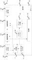
図1を参照して、本発明の第1の実施形態に係るデータパス制御システムについて説明する。本実施形態に係るデータパス制御システムは、図1に示すように、複数のモジュール101と、各モジュールを接続するリングバス102により構成される。モジュール101は、リングバス102を介して受信したデータを処理するものであり、通信部120と、通信部120に対応するデータ処理部103とを備える。なお、本実施形態では、モジュール101−1は、対応するデータ処理部103の代わりに入出力部140を備える。リングバス102は、複数のモジュール101をリング状に接続するバスである。本実施形態においては、モジュール101の通信部120がリング状にバス接続され、入出力部140が入力するデータを一方向へ転送する。このデータパス制御システムは、データ処理部103間でデータを受け渡し、複数のデータ処理部103が順次処理を実行することによりシステム全体として情報処理装置として機能する。
<<
(System configuration)
A data path control system according to a first embodiment of the present invention will be described with reference to FIG. As shown in FIG. 1, the data path control system according to the present embodiment includes a plurality of
(モジュールの機能構成)
図2には、図1におけるモジュール101の機能構成を表すブロック図を示す。ここで、モジュール101の通信部120は、ノードIDレジスタ104、パケット生成部105、パケット受信部106、待ち受けIDレジスタ107、受信制御部108、送信制御部109、パケット送信部110、ID判定部111を備える。各部は不図示のCPU等により制御される。
(Functional structure of the module)
FIG. 2 is a block diagram showing the functional configuration of the
データ処理部103は、モジュール101ごとに割り当てられた所定のデータ処理を行う。ノードIDレジスタ104は、モジュール101が生成したパケットに付加するための、モジュール101が接続されるノードのID(ノードの識別情報)を設定する。パケット生成部105は、データ処理部103で処理されたデータから、リングバス102により転送するためのパケットを生成する。パケット受信部106は、リングバス102を介して他のモジュールからパケットを受信する。待ち受けIDレジスタ107は、データ処理部103で処理すべきデータに付されるIDを記憶する。このIDは、例えば、複数のモジュールで処理を実行する順序が定まっている場合、直前の処理を実行したモジュールが付加するノードIDである。
The
受信制御部108は、パケット受信部106が受信したパケットに含まれるデータが、自モジュールで処理すべきであり、かつ処理の実行が可能な場合は、当該データをデータ処理部103に入力する。また、受信制御部108は、パケット受信部106が受信したパケットに含まれるデータが、自モジュールで処理すべきでない場合、又は処理不能である場合には、当該パケットをそのまま送信制御部109に受け渡す。送信制御部109は、データ処理部103で処理されたデータを含むパケットと、受信制御部108から受け渡されたパケットとを、リングバス102に送信するための制御を行う。パケット送信部110は、リングバス102へパケットを送信する。
The
ID判定部111は、パケット受信部106で受信したパケットに含まれるIDと、ノードIDレジスタ104と待ち受けIDレジスタ107のそれぞれに記憶されているIDとを比較し、一致判定をする。またID判定部111は、各ID値から受信制御部108及び送信制御部109の制御情報を生成する。例えば、パケットに含まれるIDが待ち受けIDレジスタ107で記憶されたIDである場合、パケットに含まれるデータを自モジュールで処理すべきである。このため、ID判定部111は、受信制御部108に、そのデータを処理部へ受け渡すように指示する制御信号を生成する。また、例えば、パケットに含まれるIDが、ノードIDレジスタ104に記憶されたIDである場合、そのパケットは自モジュールで生成し、リングバス102を1周して戻ってきたと考えられる。このため、その旨を示す制御情報を送信制御部109へ送信し、適切に送信間隔制御を実行するようにする。
The
本実施形態におけるデータパス制御システムは、モジュール101がリング状にバス接続され、リング型のネットワークトポロジになっている。また、リングバス102に接続されるモジュール101の個数に制限はない。各モジュール101は、モジュール101間で共通のサイクルごとに次のモジュール101へと1つのパケットを転送することで、それぞれのモジュール101は並列にデータ転送を行う。また、待ち受けIDレジスタ107とノードIDレジスタ104の設定を適切に行うことで、データ処理のパスを構成し、入力データを複数の処理モジュールが要求する順番で処理させることができる。
In the data path control system according to the present embodiment,
(パケット構成)
続いて、図3を参照して、本実施形態に係るモジュール101間のデータ転送に用いるパケットについて説明する。パケットは、Validフラグ201、ノードID202、データ203、及びStallフラグ204を備える。Validフラグ201は、パケットが有効か否かを示すフラグである。Validフラグ201が有効でないパケットは、例えば空パケットである。このため、モジュール101は、Validフラグ201が有効でない場合は、そのタイミングでパケットを送出できる。一方で、Validフラグが有効である場合、そのパケットは処理、又は転送をする必要がある。このため、例えば、あるタイミングにおいて転送するべきパケットが存在する場合、そのパケットと同時に他のパケットを送ることはできない。
(Packet configuration)
Subsequently, a packet used for data transfer between the
ノードID202は、パケットの送信元が付加する、接続ノードを示す識別子である。ノードID202には、パケットを送信するモジュールとパケットを受信するモジュールとの接続状態を識別可能な値(ノードID)が割り当てられている。本実施形態においては、例えば、各モジュール101は、自らの直前に処理を実行するモジュールが付加するノードIDを待ち受け、待ち受けIDレジスタ107に記憶しておく。そして、そのノードIDを含むパケットを受信すると、そのパケットに含まれるデータを処理する。データ203は、パケットが保持するデータである。Stallフラグ204は、パケットの保持するデータについて、処理を本来実行するはずのモジュールが、例えば他のデータを処理中であるなどの理由により処理を保留したことを示す。
The
(モジュールの動作)
続いて、データパス制御システムのモジュール間でのパケットの転送動作について説明する。まず、パケットの受信動作について説明する。ID判定部111は、パケット受信部106で受信したパケットに、自モジュール101のデータ処理部103において処理されるべきデータが含まれているか否かを判定する。あるいはパケットに含まれるデータが、他のモジュールにより処理されるべきか否かを判定する。判定は、受信パケットのノードID202と、待ち受けIDレジスタ107のID値とを比較することにより行う。例えば、待ち受けIDレジスタに処理すべき受信パケットのID値を格納し、IDが一致する場合に、データ処理部103で処理を行う。
(Module operation)
Subsequently, a packet transfer operation between modules of the data path control system will be described. First, a packet receiving operation will be described. The
ID判定部111は、判定結果に基づいて、受信制御部108を制御する。受信制御部108は、対応するデータ処理部103で処理されるべきパケットについては、当該パケットに含まれるデータをデータ処理部103へ出力する。そして、それ以外のパケットについては、送信制御部109へ出力する。ただし、パケットが、データ処理部103において処理されるべきデータを含む場合であっても、例えば、すでに他のデータの処理中であり、さらなる処理を実行できないなど、データ処理部103において処理できない場合がある。受信制御部108は、この状態を検知すると、処理を保留したことを示すStallフラグ204を「1」として、送信制御部109へとパケットを受け渡す。
The
次に、データ処理部103によって処理されたデータが、図3に示したパケットにより、次に処理されるべきモジュールへと送信される動作について説明する。パケット生成部105は、パケットを生成する。パケット生成部105は、パケットのデータ203にデータ処理部103で処理されたデータを格納し、ノードID202のフィールドにノードIDレジスタ104のID値を格納する。パケット生成部105は、さらに、パケットのValidフラグ201を有効にする。送信制御部109は、パケット生成部105が生成したパケット、及び受信制御部108から直接入力されたパケットを、バッファを通してリングバス102へ送信するタイミングを制御する。
Next, the operation in which the data processed by the
(送信制御部の構成例)
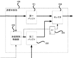
次に、図4を参照して、本実施形態に係る送信制御部109の構成例について説明する。本例における送信制御部109は、第一バッファ301、第二バッファ302、送信間隔制御部303、セレクタ304、及びタイミング調整用のFF(フリップフロップ)305を備える。第一バッファ301は、受信制御部108からのパケットを保持する。より詳細には、第一バッファ301は、受信制御部108でスルーされたパケット、又は自ノードで処理されるデータを保持したパケットであったがデータ処理部103で処理できなかったパケットを格納する。第二バッファ302は、パケット生成部105で生成された、データ処理部103で処理されたデータを含むパケットを保持する。
(Configuration example of transmission control unit)
Next, a configuration example of the
送信間隔制御部303は、第二バッファ302からのパケットの送信間隔を制御する。セレクタ304は、送信するパケットを選択する。第一バッファ301、及び第二バッファ302に格納されたパケットのうち、どちらを送信するかは、セレクタ304が選択する。このとき、送信間隔制御部303は、第二バッファ302に格納されたパケットが送信可能か否かを決定する。送信間隔制御部303は内部にタイマを持ち、タイマはパケットが送信される度に所定の値に設定され、最小のパケット送信間隔を維持する。この送信間隔はレジスタ等により設定可能であり、後段の処理を実行するモジュール101における処理能力に応じた値を設定する。なお、FF305は、後述する出力有効信号410を第一バッファ301及び第二バッファ302の出力タイミングに合わせて1サイクル遅延させる。そして、セレクタ304はFF305の出力により制御される。
The transmission
本実施形態では、受信したパケットの送信元のモジュールと自モジュールとの処理順序関係をノードID202により判定する。また、この判定結果と、受信したパケットのStallフラグ204を調べることにより、どのモジュールが処理保留状態であるかを検出する。この検出結果に応じて、第二バッファ302からの送信間隔を送信間隔制御部303により動的に制御し変更することで、パケットの転送効率を向上させることができる。具体的には、例えば、モジュール101は、自らより後段の処理を実行するモジュール101が処理保留状態であることを検出した場合、第二バッファ302に格納されたパケットの送出を一時停止する。そして、この一時停止する期間について、処理保留中のパケットの数に応じて変動させる。これにより、処理保留状態の有効なパケットでリングバス102が埋め尽くされることを防ぐと共に、少数の処理保留状態のパケットには、少しの待ち時間を与えることで、システム全体のスループットを向上させることができるようになる。
In the present embodiment, the
(送信間隔制御部の機能構成)
以下、図5を用いて、送信間隔制御部303の構成例について説明する。本例における送信間隔制御部303は、タイマ403、ロード制御部404、送信間隔選択部405、第一レジスタ406、第二レジスタ407、加算器408、リミッタ409を備える。
(Functional configuration of transmission interval control unit)
Hereinafter, a configuration example of the transmission
タイマ403は送信間隔を制御する。本実施形態では、例えば、ロードされた値から0に向けてカウントダウンするロード機能付きのダウンカウンタである。ロード制御部404はタイマ403への送信間隔のロードを制御する。ロード制御部404は、ID判定信号401、Stallフラグ402、タイマ値411を入力とし、出力有効信号410、ロード信号412を出力する。
The
ここで、ID判定信号401は、受信したパケットのIDがノードIDレジスタ104の値と等しい場合、値は「1」となる。受信したパケットのIDがノードIDレジスタ104の値と等しい場合とは、すなわち、受信パケットが過去に自モジュールで生成して送信したパケットである場合である。受信したパケットのIDがノードIDレジスタ104の値と等しくない場合、及び、受信したパケットのIDがノードIDレジスタ104の値と等しくてもValidフラグ201が無効を示す場合は、ID判定信号401の値は「0」となる。ID判定信号401は、ID判定部111から入力される。
Here, the
Stallフラグ402は受信制御部108から入力される。Stallフラグ402は、例えば、「1」の時、受信したパケットの処理を保留したことを示し、「0」の時、処理を保留していないことを示す。すなわち、ID判定信号が「1」かつStallフラグが「1」である場合は、自モジュールのデータ処理部103において処理した後のデータを含む信号を送信したが、他のモジュールで直後の処理が保留され、信号が戻ってきたことを示す。タイマ値411は、タイマ403の値を示す。
The
出力有効信号410は、送信間隔制御部303が第二バッファ302の出力間隔を制御するための信号である。出力有効信号410は、タイマ値411が「0」で、かつ、ID判定信号401とStallフラグ402が共に「1」でない場合、有効を示す値「1」となり、その他の場合は「0」となる。第二バッファ302とセレクタ304は、「1」を示す出力有効信号410を受け取ると、第二バッファに格納された信号をリングバス102上へ送出するようにする。ただし、セレクタ304には出力有効信号410がFF305を介して伝搬されるため、1サイクル遅れて、第二バッファ302の出力が選択される。ロード信号412は、ロード制御部404が、タイマ403における出力間隔のロードのタイミングを制御する信号である。ロード信号412は、タイマ値411が「0」の時、又はID判定信号401が「1」かつStallフラグ402が「1」の時、有効値「1」となり、それ以外の場合は「0」となる。すなわち、タイマ403が満了した時と、自モジュールのデータ処理部103で処理した後のデータが他モジュールで処理を保留されて戻ってきた場合に、タイマ403に送信間隔をロードさせる。
The output
送信間隔選択部405はタイマ403へロードする送信間隔を選択する。送信間隔選択部405は、ID判定信号401が「1」かつStallフラグ402が「1」の時、後述するリミッタ409の出力を選択する。それ以外の場合は後述する第一レジスタ406の値を選択する。タイマ403は、ロード信号412が「1」の場合、送信間隔選択部405で選択された値をロードし、カウントダウンを実行する。
A transmission
第一レジスタ406は最小のパケット送信間隔を確保する所定の設定値を格納する。第二レジスタ407は動的に送信間隔を制御するための被加算値を格納する。加算器408はタイマ値411と第二レジスタ407の被加算値を加算する。リミッタ409は加算器408の出力値を、所定値以下に制限する。ここで、所定値は、例えばリングバス102の一周分に相当する期間である。
The
Stallフラグ402が「1」、かつID判定信号401が「1」である場合、そのパケットは、そのパケットを受信したモジュール101が送出し、続いて処理を実行する他のモジュール101で処理を保留されて戻ってきたことを示す。このため、そのような状態を検知すると、ロード制御部404は、第二バッファ302からのデータ送出を遅らせるように、タイマを制御する。具体的には、第一レジスタ406の値より大きいリミッタ409の値をタイマ403にロードする。さらに、ID判定信号401とStallフラグ402が共に「1」であるパケットを多数検知すると、それに応じてカウンタにロードする値を加算器408により、増加させる。ID判定信号401とStallフラグ402が共に「1」であるパケットの数に応じて適切な待ち時間を設定することが可能となる。さらに、リミッタ409を用いることにより、待ち時間を一定の時間以内に抑えることができる。これにより、モジュールが、他のモジュールにおける処理保留状態が解消された後であっても待ち続けることを防ぎ、システム全体のスループットの低下を防ぐことができる。
When the
(送信間隔制御部の動作)
次に、図6を用いて、送信間隔制御部303の動作を説明する。本実施形態では、図1のモジュール数がn=16の場合に関して説明する。また、リミッタ409は加算器408の出力値をリングバス102の一周分に相当する16以下に制限する。
(Operation of transmission interval controller)
Next, the operation of the transmission
ここでは説明を簡単にするため、リングバス102の状態は考慮しない。すなわち、リングバス102が有効パケットで埋め尽くされているなどの事情はないものとし、タイマ403が「0」の時に第二バッファ302からパケットを送信することができるものとする。なお、下記では説明しないが、リングバス102上の送信スロットが空でない場合、すなわち、受信パケットのValidフラグ201が有効であり、その受信パケットを転送する必要がある場合は、第二バッファ302からパケットの送信ができない。これに限らず、パケットの送信ができない場合は、タイマ403は第一レジスタ406の値のロードを保留し、タイマ403は「0」を維持する。ただし、Stallフラグ402が「1」かつID判定信号401が「1」の場合は、タイマ403が上記のように「0」を維持する状態であっても、送信間隔選択部405により、リミッタ409の値がロードされる。
Here, for simplicity of explanation, the state of the
まず初期設定として、不図示のCPU等から、第一レジスタ406と第二レジスタ407の値が設定される。本実施形態では、一例として、第一レジスタ406に「1」を、第二レジスタ407に「3」を設定する。また、サイクル0におけるID判定信号401、Stallフラグ402、タイマ値411の値をそれぞれ「0」、「0」、「1」とする。また、ID判定信号401、及びStallフラグ402は、図6に示すように推移するものとする。
First, as initial settings, values of the
サイクル0ではID判定信号401及びStallフラグ402が共に「0」である。すなわち、受信したパケットは、自モジュールから送信したものでなく、また、処理が保留されてもいない。ここで、タイマ値411が「1」であるため、タイマのロードは不要であり、ロード信号412は「0」となる。このため、タイマ403は、送信間隔選択部405が選択した値をロードすることなく、ダウンカウントし、次のサイクル1で「0」となる。また、出力有効信号410は、タイマ値411が「0」でないため、無効を示す「0」となる。なお、加算器408の出力はタイマ値411(「1」)と第二レジスタ407(「3」)を加算した「4」となる。リミッタ409の出力はリミット値16に達していないため、加算器408の値がそのまま出力され「4」となる。送信間隔選択部405は、ID判定信号401とStallフラグ402が共に「1」でないため、第一レジスタ406に格納された値「1」を選択する。つまり、このサイクルでは、モジュール101が自ら送信したパケットが他のモジュールで保留されて戻ってきたものでなく、かつ、タイマ値が「0」でないため、タイマへの値のロードや、第二バッファ302からのパケットの出力は行わない。
In
サイクル1では、ID判定信号401が「1」、Stallフラグ402が「0」である。すなわち、モジュール101が自ら送信したパケットを受信した状態であるが、他のモジュールにより処理の保留はされていないことを示す。この場合は、自ら送信したパケットが必要のないものであるため、パケットを消去し空パケットにする。なお、タイマ値411は「0」であるため、ID判定信号401、Stallフラグ402の値によらず、ロード信号412は「1」となり、送信間隔選択部405で選択された値が、次のサイクルでタイマ403にロードされる。送信間隔選択部405は、ID判定信号は「1」であるが、Stallフラグ402が「1」でないため、第一レジスタ406に格納された値「1」を選択する。なお、加算器408の出力はタイマ値411(「0」)に第二レジスタ407(「3」)の値を加えた3となる。リミッタ409の出力はリミット値16に達していないため加算器408の値がそのまま出力され「3」となる。また、出力有効信号410はタイマ値411が「0」であるため「1」となる。つまり、このサイクルでは、タイマ値が「0」で、かつ、ID判定信号401とStallフラグ402が共に「1」でないため、第一レジスタ406に格納された所定の設定値をタイマにロードし、第二バッファ302からのパケットの出力を行う。
In
サイクル2ではサイクル0と同様、ID判定信号401及びStallフラグ402が共に「0」である。このため、ロード信号412、出力有効信号410、加算器408の出力、リミッタ409の出力、送信間隔選択部405の出力はそれぞれ、「0」、「0」、「4」、「4」、「1」となる。またタイマ403は1からダウンカウントして次のサイクル3で「0」となる。
In
サイクル3ではID判定信号401が「0」であり、Stallフラグ402が「0」である。しかし、タイマ値411が「0」のため、ロード信号412は「1」となり、次のサイクル4でタイマ403に値がロードされる。また、出力有効信号410は、タイマ値411が「0」で、かつ、ID判定信号401とStallフラグが共に「1」でないため、「1」となる。なお、加算器408の出力はタイマ値411(「0」)に第二レジスタ407(「3」)の値を加えた3となり、リミッタ409の出力はリミット値16に達していないため加算器408の値がそのまま出力され「3」となる。送信間隔選択部405は、Stallフラグ402、ID判定信号401共に「0」であるため、第一レジスタ406の値を選択し「1」を出力する。
In
サイクル4ではサイクル0と同様、ID判定信号401及びStallフラグ402が共に「0」である。このため、ロード信号412、出力有効信号410、加算器408の出力、リミッタ409の出力、送信間隔選択部405の出力はそれぞれ、「0」、「0」、「4」、「4」、「1」となる。またタイマ403は1からダウンカウントして次のサイクル5で「0」となる。
In
サイクル5ではID判定信号401が「1」、Stallフラグ402が「1」である。すなわち、モジュール101が出力したパケットが、続いて処理を実行すべき他のモジュール101により処理を保留され、戻ってきた状態である。このため、ロード信号412は「1」となり、次のサイクル6でタイマ403に送信間隔選択部405で選択した値をロードする。なお、加算器408の出力はタイマ値411(「0」)に第二レジスタ407(「3」)の値を加えた3となる。リミッタ409の出力はリミット値16に達していないため加算器408の値がそのまま出力され「3」となる。送信間隔選択部405は、ID判定信号401が「1」かつStallフラグ402が「1」であるため、リミッタ409の値を選択し「3」を出力する。また、出力有効信号410はタイマ値411が「0」であるが、ID判定信号401とStallフラグ402が共に「1」であるため「0」となる。つまり、このサイクルでは、受信パケットが自モジュール出力のもので、続いて処理を実行すべきモジュールにて保留されたことを検知したため、第一レジスタ406の値より長い値「3」を次のサイクル6でタイマにロードし、送信間隔を延長する。なお、カウンタ値が「0」であるが、受信した保留パケットは有効であり転送する必要があるため、第二バッファ302からのパケットの出力は行われない。
In
サイクル6〜8ではサイクル0と同様、ID判定信号401及びStallフラグ402が共に「0」である。このため、ロード信号412、出力有効信号410、加算器408の出力、リミッタ409の出力、送信間隔選択部405の出力はそれぞれ、「0」、「0」、「6」〜「4」、「6」〜「4」、「1」となる。またタイマ403は「3」からダウンカウントしていき、次のサイクル9で「0」となる。
In
サイクル9ではサイクル3と同様に、ID判定信号401と、Stallフラグ402が共に「0」であり、タイマ値411が「0」である。このため、ロード信号412は「1」となり、次のサイクル10でタイマ403に値がロードされる。また、出力有効信号410は「1」となる。なお、加算器408の出力はタイマ値411(「0」)に第二レジスタ407(「3」)の値を加え、3となる。リミッタ409の出力はリミット値16に達していないため加算器408の値がそのまま出力され「3」となる。送信間隔選択部405は、Stallフラグ402が「1」でないため、第一レジスタ406を選択し「1」を出力する。つまり本サイクルでは、受信されたパケットが保留されたものでない。ただし、タイマ値411が「0」のため、第一レジスタ406に格納された所定の設定値をタイマにロードし、第二バッファ302からのパケットの出力を行う。
In
サイクル10ではサイクル0と同様、ID判定信号401及びStallフラグ402が共に「0」である。このため、ロード信号412、出力有効信号410、加算器408の出力、リミッタ409の出力、送信間隔選択部405の出力はそれぞれ、「0」、「0」、「4」、「4」、「1」となる。またタイマ403は1からダウンカウントして次のサイクル11で「0」となる。
In
サイクル11ではサイクル5と同様、ID判定信号401が「1」、Stallフラグ402が「1」である。このため、ロード信号412、出力有効信号410、加算器408の出力、リミッタ409の出力、送信間隔選択部405の出力はそれぞれ、「1」、「0」、「3」、「3」、「3」となる。また、次のサイクル12でタイマ403に「3」がロードされる。
In
サイクル12ではサイクル0と同様、ID判定信号401及びStallフラグ402が共に「0」である。このため、ロード信号412、出力有効信号410、加算器408の出力、リミッタ409の出力、送信間隔選択部405の出力はそれぞれ、「0」、「0」、「6」、「6」、「1」となる。またタイマ403は3からダウンカウントして次のサイクル13で「2」となる。
In
サイクル13ではID判定信号401が「1」、Stallフラグ402が「1」であるため、ロード信号412は「1」となり、次のサイクル14でタイマ403に値がロードされる。なお、加算器408の出力はタイマ値411(「2」)に第二レジスタ407(「3」)の値を加えた5となる。リミッタ409の出力はリミット値16に達していないため加算器408の値がそのまま出力され「5」となる。送信間隔選択部405は、ID判定信号401が「1」かつStallフラグ402が「1」であるため、リミッタ409を選択し「5」を出力する。また、出力有効信号410はタイマ値411が「0」でないため、「0」となる。つまり、このサイクルでは、サイクル11に引き続き、モジュール101は、自ら出力したパケットが続いて処理すべきモジュールにて保留され、戻ってきたものを受信している。ID判定信号401とStallフラグ402が共に「1」のパケットを短期的に複数受信するということは、続いて処理すべきモジュールにおいて、多くの処理が滞っていると考えられる。このため、タイマ403に、より長い時間をロードして、処理の保留を解消すべきである。このため、第二レジスタ407に格納された動的に送信間隔を制御するための被加算値とタイマ値との加算結果「5」を次のサイクル14でタイマにロードし、送信間隔をさらに伸ばす。
In
サイクル14〜16はサイクル13と同様であり、順次送信間隔を延長する。ロード信号412、出力有効信号410の出力はそれぞれ、「1」、「0」であり、加算器408の出力、リミッタ409の出力、送信間隔選択部405はそれぞれ「8」「11」「14」と変化する。またタイマ403には、サイクルごとにリミッタ409の出力がロードされ、「5」、「8」、「11」と第二レジスタ407の値「3」ずつロードされる間隔が加算されていき、サイクル17で「14」となる。つまり、これらのサイクルでは、モジュール101が送信したパケットが、続いて処理すべき他のモジュール101において複数保留され、保留パケットの発生頻度が高い状態である。よって、第二レジスタ407に格納された被加算値とタイマ値との加算結果をタイマにロードし、送信間隔を段階的に延長する。
サイクル17ではサイクル13と同様であるが、加算器408の出力が「16」より大きい「17」であるため、リミッタ409は、値を「16」に制限する。すなわち、ロード信号412、出力有効信号410、加算器408の出力、リミッタ409の出力、送信間隔選択部405の出力はそれぞれ、「1」、「0」、「17」、「16」、「16」となる。また、次のサイクル18でタイマ403に「16」がロードされる。
The
サイクル18〜33ではサイクル0とサイクル0と同様、ID判定信号401及びStallフラグ402が共に「0」である。このため、ロード信号412、出力有効信号410、送信間隔選択部405の出力はそれぞれ「0」、「0」、「1」である。また、加算器408の出力は「19」〜「4」となり、リミッタ409の出力は、加算器408の出力が16以上の場合は「16」であり、その他の場合は加算器408の出力と同一値となる。またタイマ403は「16」からダウンカウントしていき、サイクル34で「0」となる。つまり、これらのサイクルでは、モジュール101が出力したパケットが、続いて処理すべき他のモジュール101で処理を保留されて戻ってきていないため、タイマ値411が「0」になるまでダウンカウントする。これにより、モジュール101は、タイマ値411が「0」となるまで第二バッファ302からのパケットの出力を停止し、続いて処理を実行する他のモジュール101における処理の保留が解消するのを待つことになる。これにより、処理を保留された有効なパケットがリングバス102を埋め尽くすことによるデッドロック、及び効率の低下を回避することが可能となる。
In cycles 18 to 33, as in
サイクル34ではサイクル3と同条件であり、ロード信号412、出力有効信号410、加算器408の出力、リミッタ409の出力、送信間隔選択部405の出力はそれぞれ、「1」、「1」、「3」、「3」、「1」となる。また、次のサイクル35でタイマ403に「1」がロードされる。
In the
以上説明したように、モジュール101が、自らが出力したパケットが、続いて処理すべき他のモジュール101で処理を保留されて戻ってきたことを検知すると、その頻度によって、動的に第二バッファ302からのパケットの送信間隔を制御する。また、それ以外のパケットについては、タイマ403が「0」になる度に最小のパケット送信間隔の所定の値をロードし、最小のパケット出力間隔を保証する。これらの制御により、続いて処理を実行する他のモジュール101がパケットを受け付け可能な間隔でのパケット出力が可能となる。また、これにより、続いて処理を実行する他のモジュール101からの保留パケットの発生を抑制し、パケットの転送効率を向上させることが可能となる。
As described above, when the
<<実施形態2>>
次に、本発明の第2の実施形態に係るデータパス制御システムについて説明する。図1から4に係る構成は第1の実施形態と同様のため、説明を省略する。以下、図7を用いて、本実施形態に係る送信間隔制御部303の構成について説明する。なお、図7において、図5と同一の機能を有するブロックは同一の番号を付し、説明を省略する。
<<
Next, a data path control system according to the second embodiment of the present invention will be described. Since the configuration according to FIGS. 1 to 4 is the same as that of the first embodiment, the description thereof is omitted. Hereinafter, the configuration of the transmission
(送信間隔制御部の第二の構成例)
ID判定信号501は、図5の例と同様、ID判定部111から入力される。受信したパケットのノードID202がノードIDレジスタ104の値と等しい、すなわち、自モジュールが出力したことを示す場合、値を「01」とする。なお、「**」は2ビットの値**を示す。また、受信したパケットのノードID202が自モジュールより後に処理されたことを示す場合は「10」となる。それ以外の場合は値「00」である。なお、ここでは処理の上流側より昇順にノードIDを付すこととし、自モジュールより後段に位置するか否かの判定はパケットのノードID202とノードIDレジスタ104に記憶された値との大小比較によって行う。すなわち、受信パケットのノードID202が自モジュールのノードIDレジスタ104の値よりも大きい場合、後段のモジュールで処理された後に送信されたパケットと判断する。また、ノードID202の値によらず、Validフラグ201が無効を示す場合は「00」を出力する。
(Second configuration example of transmission interval control unit)
The
504はタイマ403へ送信間隔のロードを制御するためのロード制御部であり、ID判定信号501、Stallフラグ402、タイマ値411が入力され、出力有効信号510、ロード信号512を出力する。ここでは説明を簡単にするため、タイマ403が「0」の時に、第二バッファ302からパケットの送信ができるものとする。
送信間隔選択部505は、ID判定信号501が「01」かつStallフラグ402が「1」の時、リミッタ409の出力をタイマ403へロードする送信間隔として選択する。また、送信間隔選択部505は、ID判定信号501が「10」かつStallフラグ402が「1」の時、後述する第二リミッタ509の出力を選択する。それ以外の場合は第一レジスタ406の値を選択する。すなわち、実施形態1と異なり、モジュール101は、自らの処理より後に処理を実行する他のモジュール101において処理が保留された場合にも、第二バッファ302からのパケットの送信間隔を延長する。すなわち、モジュール101の直後の処理を実行する他のモジュール101のみでなく、そのさらに後に処理を実行する他のモジュールにおける処理の保留が解消するまで、送信を待つこととなる。これにより、デッドロックとなる確率をさらに低減し、システム全体のスループットを向上させることができる。
When the
第三レジスタ507は自モジュールより後に処理されるモジュールからの保留パケットを検知した時、動的に送信間隔を制御するための被加算値を設定するレジスタである。ここで、第二レジスタ407には第一の所定値を、第三レジスタ507には、第一の所定値と異なる第二の所定値を格納しておく。なお、第一の所定値は、自モジュールの直後の処理を実行するモジュールで処理が保留されているので、第二の所定値より大きい値であることが望ましい。逆に第二の所定値は、自モジュールの直後の処理よりさらに後の処理を実行するモジュールにおいて処理が保留されたことを検知した場合にパケットの送信間隔を延長するものである。したがって、上流のモジュールでは、第二の所定値を用いて送信間隔を延長する頻度が下流のモジュールに比べて高くなる。このため、個々のモジュールで延長する送信間隔の量は大きくなくても良く、小さい値でよい。第二加算器508は、加算器408と同様に、タイマ値411と第三レジスタ507の値を加算する。第二リミッタ509は、リミッタ409と同様に、第二加算器508の出力値を所定値以下に制限する。所定値は、例えばリングバス102の一周分に相当する期間である。出力有効信号510は、ロード制御部504から第二バッファ302へ出力間隔を制御するために出力される信号である。出力有効信号510は、タイマ値411が「0」の場合で、ID判定信号501が「01」又は「10」でStallフラグ402が「1」である場合以外の時、有効を示す値「1」であり、そのほかの場合は「0」である。すなわち、タイマ値411が「0」であり、かつ、Stallフラグ402が1であってもID判定信号501が「00」であるような場合は、出力有効信号510は「1」となる。一方、タイマ値411が「0」であっても、Stallフラグ402が1でID判定信号501が「01」や「10」であるような場合は、出力有効信号510は「0」となる。ロード信号512は、ロード制御部504からタイマ403へ、出力間隔をロードするタイミングを制御する信号である。ロード信号512は、タイマ値411が「0」、又はStallフラグ402が「1」、かつID判定信号501が「01」若しくは「10」の時、有効値「1」となる。それ以外の場合は「0」となる。
The
(送信間隔制御部の第二の動作例)
次に図8を用いて、本実施形態に係る送信間隔制御部303の動作を説明する。本実施形態では、実施形態1と同様に、図1のモジュール数nが16である場合に関して説明する。よって、リミッタ409及び509は、加算器408及び508の出力値をリングバスの一周分に相当する16により制限する。
(Second operation example of transmission interval control unit)
Next, the operation of the transmission
まず初期設定として、図示していないCPU等から第一レジスタ406、407及び507の値が設定される。本実施形態では一例として、第一レジスタ406に「1」を、第二レジスタ407に「3」、第三レジスタ507に「1」を設定する。また、サイクル0におけるID判定信号501、Stallフラグ402、タイマ403の値をそれぞれ、「00」、「0」、「1」とする。
First, as initial settings, values of the
サイクル0ではID判定信号501は「00」及びStallフラグ402が「0」であるため、ロード信号512は「0」であり、タイマ403は1からダウンカウントして次のサイクル1で「0」となる。また、出力有効信号510はタイマ値411が「0」でないため、「0」となる。なお、加算器408の出力はタイマ値411「1」に第二レジスタ407の値「3」を加え、「4」となる。リミッタ409の出力はリミット値16に達していないため加算器408の値がそのまま出力され「4」となる。また、第二加算器508の出力は、タイマ値411「1」に第三レジスタ507の値「1」を加え「2」となる。第二リミッタ509の出力はリミット値「16」に達していないため第二加算器508の値がそのまま出力され「2」となる。送信間隔選択部505は、ID判定信号501が「01」又は「10」でなく、また、Stallフラグ402が「1」でないため、第一レジスタ406を選択し「1」を出力する。つまり本サイクルでは、受信パケットが保留されたものでもなくかつ、タイマ値が「0」でないため、タイマへの値のロードや、第二バッファ302からのパケットの出力は行わない。
In
サイクル1ではID判定信号501が「01」、Stallフラグ402が「0」である。すなわち、モジュール101は、自らが出力したパケットを受信しているが、処理は保留されていない。一方、タイマ値411は「0」である。このため、ロード信号512は「1」となり、次のサイクル2でタイマ403に値がロードされる。また、出力有効信号510はタイマ値411が「0」であって、かつ、Stallフラグ402が「1」及びID判定信号501が「01」又は「10」の場合に該当しないため、「1」となる。なお、加算器408の出力はタイマ値411「0」に第二レジスタ407の値「3」を加え「3」となる。リミッタ409の出力はリミット値16に達していないため加算器408の値がそのまま出力され「3」となる。また、第二加算器508の出力はタイマ値411「0」に第三レジスタ507の値「1」を加え「1」となる。第二リミッタ509の出力はリミット値16に達していないため第二加算器508の値がそのまま出力され「1」となる。送信間隔選択部505は、Stallフラグ402が「1」でないため、第一レジスタ406の値「1」を選択する。つまり、このサイクルでは、受信パケットが保留されたものでないが、タイマ値が「0」のため、第一レジスタ406に格納された所定の設定値をタイマ403にロードし、第二バッファ302からのパケットの出力を行う。
In
サイクル2ではID判定信号501が「10」である以外は、サイクル0と同様である。ロード信号512、出力有効信号510、加算器408の出力、リミッタ409の出力、第二加算器508の出力、第二リミッタ509の出力、送信間隔選択部505の出力はそれぞれ、「0」、「0」、「4」、「4」、「2」、「2」、「1」となる。またタイマ403は1からダウンカウントして次のサイクル3で「0」となる。
サイクル3ではID判定信号501が「00」、Stallフラグ402が「0」である。しかし、タイマ値411が「0」であるため、ロード信号512は「1」となり、次のサイクル4でタイマ403に値がロードされる。また、出力有効信号510はタイマ値411が「0」であって、かつ、Stallフラグ402が「1」及びID判定信号501が「01」又は「10」の場合に該当しないため、「1」となる。なお、加算器408の出力はタイマ値411「0」に第二レジスタ407の値「3」を加え「3」となる。リミッタ409の出力はリミット値16に達していないため加算器408の値がそのまま出力され「3」となる。また、第二加算器508の出力はタイマ値411「0」に第三レジスタ507の値「1」を加え1となる。第二リミッタ509の出力はリミット値16に達していないため加算器408の値がそのまま出力され「1」となる。送信間隔選択部505は、Stallフラグ402が「1」であるがID判定信号501が「00」であるため、第一レジスタ406の値「1」を選択する。つまり、このサイクルでは、受信パケットが保留されたものであるが、自モジュール以降の処理パス上のモジュールが出力したパケットが保留されたわけではない。ただし、タイマ403が「0」のため、第一レジスタ406に格納された最小のパケット送信間隔を保証する所定の設定値をタイマにロードし、第二バッファ302からのパケットの出力を行う。
In
サイクル4はサイクル0と同様である。ロード信号512、出力有効信号510、加算器408の出力、リミッタ409の出力、第二加算器508の出力、第二リミッタ509の出力、送信間隔選択部505の出力はそれぞれ、「0」、「0」、「4」、「4」、「2」、「2」、「1」となる。またタイマ403は1からダウンカウントして次のサイクル5で「0」となる。
サイクル5ではID判定信号401が「01」、Stallフラグ402が「1」である。また、タイマ値411が「0」であるため、ロード信号512は「1」となり、次のサイクル6でタイマ403に値がロードされる。また、出力有効信号510はタイマ値411が「0」であるが、かつ、Stallフラグ402が「1」及びID判定信号501が「01」又は「10」の場合に該当するため、「0」となる。なお、加算器408の出力はタイマ値411「0」に第二レジスタ407の値「3」を加え「3」となる。リミッタ409の出力はリミット値16に達していないため加算器408の値がそのまま出力され「3」となる。また、第二加算器508の出力はタイマ値411「0」に第三レジスタ507の値「1」を加え「1」となり、第二リミッタ509の出力はリミット値16に達していないため第二加算器508の値がそのまま出力され「1」となる。送信間隔選択部505は、ID判定信号501が「01」かつStallフラグ402が「1」であるため、リミッタ409を選択し「3」を出力する。つまり、このサイクルでは、モジュール101が、自ら送信したパケットが、続いて処理を実行すべきモジュール101にて保留され戻ってきている。よって、第二レジスタ407に格納された被加算値とタイマ値との加算結果「3」を次のサイクル6でタイマにロードし、送信間隔を伸ばす。なお、タイマ値411が「0」であるが上記保留パケットがリングバス102上にあるため第二バッファ302からのパケットの出力は行われない。
In
サイクル6〜8はサイクル0と同様である。ロード信号512、出力有効信号510、加算器408の出力、リミッタ409の出力はそれぞれ、「0」、「0」、「6」〜「4」、「6」〜「4」である。また、第二加算器508の出力、第二リミッタ509の出力、送信間隔選択部505の出力はそれぞれ、「4」〜「2」、「4」〜「2」、「1」となる。さらにタイマ403は「3」からダウンカウントしていき、次のサイクル9で「0」となる。
Cycles 6-8 are the same as
サイクル9はサイクル3と同様である。ロード信号512、出力有効信号510、加算器408の出力、リミッタ409の出力はそれぞれ、「1」、「1」、「3」、「3」である。また、第二加算器508の出力、第二リミッタ509の出力、送信間隔選択部505の出力は、それぞれ「1」、「1」、「1」となる。また次のサイクル10で第一レジスタ406の設定値をタイマにロードし、第二バッファ302からのパケットの出力を行う。
サイクル10はサイクル0と同様である。ロード信号512、出力有効信号510、加算器408の出力、リミッタ409の出力、第二加算器508の出力、第二リミッタ509の出力、送信間隔選択部505の出力はそれぞれ、「0」、「0」、「4」、「4」、「2」、「2」、「1」となる。またタイマ403は1からダウンカウントして次のサイクル11で「0」となる。
サイクル11ではID判定信号401が「10」、Stallフラグ402が「1」である。さらに、タイマ値411が「0」であるため、ロード信号512は「1」となり、次のサイクル12でタイマ403に値がロードされる。また、出力有効信号510はタイマ値411が「0」であるが、かつ、Stallフラグ402が「1」及びID判定信号501が「10」の場合であるため、「0」となる。なお、加算器408の出力はタイマ値411「0」に第二レジスタ407の値「3」を加え「3」となる。リミッタ409の出力はリミット値16に達していないため加算器408の値がそのまま出力され「3」となる。また、第二加算器508の出力はタイマ値411「0」に第三レジスタ507「1」を加え「1」となり、第二リミッタ509の出力はリミット値16に達していないため第二加算器508の値がそのまま出力され「1」となる。送信間隔選択部505は、ID判定信号501が「10」かつStallフラグ402が「1」であるため、第二リミッタ509の値を選択し「1」を出力する。つまり本サイクルでは、モジュール101は、自らより後に処理を実行する他のモジュール101において処理を保留したパケットを受信している。よって、第三レジスタ507に格納された被加算値とタイマ値との加算結果「1」を次のサイクル12でタイマにロードし、送信間隔を動的に伸ばす。なお、タイマ値411が「0」であるが、保留パケットがリングバス102上にあるため、第二バッファ302からのパケットの出力は行われない。
In
サイクル12はサイクル0と同様である。ロード信号512、出力有効信号510、加算器408の出力、リミッタ409の出力、第二加算器508の出力、第二リミッタ509の出力、送信間隔選択部505の出力はそれぞれ、「0」、「0」、「4」、「4」、「2」、「2」、「1」となる。またタイマ403は1からダウンカウントして次のサイクル13で「0」となる。
サイクル13はサイクル3と同様である。ロード信号512、出力有効信号510、加算器408の出力、リミッタ409の出力、第二加算器508の出力、第二リミッタ509の出力、送信間隔選択部505の出力はそれぞれ、「1」、「1」、「3」、「3」、「1」、「1」、「1」となる。また次のサイクル14で第一レジスタ406の設定値をタイマにロードし、第二バッファ302からのパケットの出力を行う。
サイクル14〜15はサイクル5と同様である。ロード信号512、出力有効信号510、加算器408の出力、リミッタ409の出力はそれぞれ、「1」、「0」、「4」〜「7」、「4」〜「7」である。また、第二加算器508の出力、第二リミッタ509の出力、送信間隔選択部505の出力はそれぞれ、「2」〜「5」、「2」〜「5」、「4」〜「7」となる。さらにタイマ403は毎サイクル、リミッタ409の出力がロードされ、「1」から「4」、「4」から「7」へと、第二レジスタ407の値「3」ずつ送信間隔が伸びる。つまりこれらのサイクルでは、モジュール101が出力し、次の処理を実行すべきモジュール101で保留され戻ってきたパケットを受信している。このため、第二レジスタ407に格納された被加算値とタイマ値との加算結果をタイマにロードし、送信間隔を動的に延長する。
サイクル16〜17はサイクル11と同様である。ロード信号512、出力有効信号510、加算器408の出力、リミッタ409の出力の出力はそれぞれ、「1」、「0」、「10」〜「11」、「10」〜「11」となる。また、第二加算器508の出力、第二リミッタ509の出力、送信間隔選択部505「8」〜「9」、「8」〜「9」、「8」〜「9」となる。さらに、タイマ403は毎サイクル、第二リミッタ509の出力がロードされ、「7」から「8」、「8」から「9」へと第三レジスタ507の値「1」ずつ送信間隔が延長される。つまり、これらのサイクルでは、モジュール101より後に処理を実行する他のモジュール101が出力し、保留されたパケットを受信している。よって、第三レジスタ507に格納された被加算値とタイマ値との加算結果をタイマにロードし、送信間隔を動的に延長する。
サイクル18〜19はサイクル5と同様である。ロード信号512、出力有効信号510、加算器408の出力、リミッタ409の出力の出力はそれぞれ、「1」、「0」、「12」〜「15」、「12」〜「15」となる。また、第二加算器508の出力、第二リミッタ509の出力、送信間隔選択部505の出力はそれぞれ、「10」〜「13」、「10」〜「13」、「12」〜「15」となる。さらに、毎サイクル、タイマ403にリミッタ409の出力がロードされ、「9」から「12」、「12」から「15」へと第二レジスタ407の値「3」ずつ送信間隔が延長される。
サイクル20ではサイクル5と同条件であるが、加算器408の出力が「16」より大きいためリミッタ409で「16」に制限されて出力される。すなわち、加算器408の出力、リミッタ409の出力、第二加算器508の出力、第二リミッタ509の出力、送信間隔選択部505の出力はそれぞれ、「18」、「16」、「16」、「16」、「16」となる。なお、ロード信号512、出力有効信号510は「1」、「0」である。また、次のサイクル21でタイマ403に「16」がロードされる。
In
サイクル21はサイクル11と同様であるが、第二加算器508の出力が「16」より大きいため第二リミッタ509で「16」に制限されて出力される。すなわち、加算器408の出力、リミッタ409の出力、第二加算器508の出力、第二リミッタ509の出力、送信間隔選択部505の出力はそれぞれ、「19」、「16」、「17」、「16」、「16」となる。ロード信号512、出力有効信号510は「1」、「0」となる。また、次のサイクル22でタイマ403に「16」がロードされる。
The
サイクル22〜37はサイクル0と同様である。ロード信号512、出力有効信号510、加算器408の出力、リミッタ409の出力の出力はそれぞれ、「0」、「0」、「19」〜「4」、「16」 〜「4」となる。また、第二加算器508の出力、第二リミッタ509の出力、送信間隔選択部505の出力はそれぞれ、「17」〜「2」、「16」〜「2」、「1」となる。さらに、タイマ403は「16」からダウンカウントしていき、サイクル38で「0」となる。つまりこれらのサイクルでは、他のモジュールで処理を保留されたパケットを受信していないため、タイマをダウンカウントしていき、「0」になるまで第二バッファ302からのパケットの出力を停止する。
サイクル38はサイクル3と同条件である。ロード信号512、出力有効信号510、加算器408の出力、リミッタ409の出力、第二加算器508の出力、第二リミッタ509の出力、送信間隔選択部505の出力はそれぞれ、「1」、「1」、「3」、「3」、「1」、「1」、「1」となる。また、次のサイクル39でタイマ403に「1」がロードされる。
The
以上説明したように、モジュール101は、自らが出力し、直後の処理を実行すべきモジュール101において処理を保留され戻ってきたパケットを受信した場合、その頻度によって大きさが変動する送信間隔の値をタイマ403にロードする。また、モジュール101は、自らの直後のみならず、その後に処理を実行すべき他のモジュール101で処理が保留されたパケットを受信した場合においても、その頻度によって大きさが変わる送信間隔の値をタイマ403にロードする。さらに、上記以外のパケットを受信した場合は、パケットを出力する度に最小のパケット送信間隔の所定の値をロードし、最小のパケット出力間隔とする。これらの制御により、自モジュールより後に処理を実行する他のモジュール101からの保留パケットの発生を検出し、出力間隔を動的に増加させる。これにより、処理が保留されたモジュール101より前に処理を実行する複数のモジュール101において、送信間隔を延長することとなり、パケットの転送効率をさらに向上させることが可能となる。特に、上流の処理を実行するモジュール101であるほど、出力間隔が延長される頻度が高くなるので、リングバス102の安定性が向上する。つまり、上流側のモジュール101において、下流側で処理が保留されていることを検知し、処理の対象となるパケットの送信を限定することにより、処理が保留されたパケットの発生を抑え、全体としてパケットの転送効率を向上させる。特に、処理が保留されたパケットの受信頻度に応じて動的にパケット転送量が制御されるため、モジュールのデータ処理能力が一定でなく動的に変わる場合であっても対応できる。
As described above, when the
なお、本実施形態に係る制御システムを有効に動作させるには、上述の第二レジスタ407に格納される第一の所定値を第三レジスタ507に格納される第二の所定値より大きくすることが望ましい。第二の所定値は、処理を保留しているモジュール101より上流で処理を実行したモジュール101の各々において出力間隔として加算されるため、小さい値であっても、処理の保留を解消するのに十分となることが多いからである。また、パケットの出力時にタイマにロードする値は、次段のモジュールのパケット入力間隔に合わせることが望ましい。また、上記出力間隔の増分のリミット値は、リングバス102の一周分とするのが望ましい。これは、リングバス102の一周に相当する期間だけ待てば、保留状態が解除されたかどうかを判定することができるからである。このように上限値を設けることで、保留状態が解除されてからの応答を速くし、入力待ち状態となっている時間を最小化する効果がある。
In order to effectively operate the control system according to the present embodiment, the first predetermined value stored in the
また、上記説明ではパケット出力有効信号はタイマの値で判定していたが、次段のモジュールの入力バッファが2パケット分以上ある場合、タイマは、値を「0」で維持せず、送信間隔選択部505で選択した値をロードしてもよい。この場合、タイマの値が「0」のサイクルにおいてパケットを出力できなかったか否かの出力判定を実行し、出力できなかったと判定された場合、その旨を示す情報として、出力保留フラグを設け、当該出力保留フラグを「1」にセットする。そして、タイマは送信間隔選択部505で選択した値をロードする。そして、ロード制御部504は、タイマの値が「0」であるか、出力保留フラグが「1」である場合、出力有効信号510を、有効を示す「1」としてもよい。この場合、局所的な最小出力間隔は保証されないが、次段のモジュールでは保留とはならないため、さらに効率的なパケット転送が可能となる。また、上述の実施形態では、タイマとしてダウンカウンタを有する構成について説明したが、ダウンカウンタの代わりにアップカウンタを配置して、設定されている送信間隔を計測する構成としてもよい。
In the above description, the packet output valid signal is determined by the value of the timer. However, if the input buffer of the next module has two or more packets, the timer does not maintain the value at “0” and the transmission interval The value selected by the
<<その他の実施形態>>
また、本発明は、以下の処理を実行することによっても実現される。即ち、上述した実施形態の機能を実現するソフトウェア(プログラム)を、ネットワーク又は各種記憶媒体を介してシステム或いは装置に供給し、そのシステム或いは装置のコンピュータ(またはCPUやMPU等)がプログラムを読み出して実行する処理である。
<< Other Embodiments >>
The present invention can also be realized by executing the following processing. That is, software (program) that realizes the functions of the above-described embodiments is supplied to a system or apparatus via a network or various storage media, and a computer (or CPU, MPU, or the like) of the system or apparatus reads the program. It is a process to be executed.
101 モジュール
102 リングバス
103 処理部
104 ノードIDレジスタ
105 パケット生成部
106 パケット受信部
107 待ち受けIDレジスタ
108 受信制御部
109 送信制御部
110 パケット送信部
111 ID判定部
101
Claims (11)
前記複数の通信手段の少なくとも1つは、
受信したデータについて、前記予め定めた順序において自通信手段に対応する処理手段よりも後段で処理を実行するべき処理手段の少なくとも1つにおいて処理が保留されたことを示す情報を検知する検知手段と、
対応する処理手段が処理を実行した後のデータを最後に送信してから前記所定の送信間隔以上の間隔を置いて、前記対応する処理手段が処理を実行した後のデータを送信する送信手段と、
前記検知手段によって前記受信したデータに対する処理が保留されたことを示す情報が検知された場合に、前記送信間隔を延長するように制御する制御手段と、を有し、
前記制御手段は、前記検知手段が前記受信したデータに対する処理が保留されたことを示す情報を検知した頻度に応じた延長時間によって、前記送信間隔を延長し、
前記制御手段は、
ロードした値から0に向けてカウントダウンするタイマと、
前記タイマが示す値に応じて出力が有効であるかを示す出力有効信号を出力する出力有効信号出力手段と、を有し、
前記送信手段は、前記出力有効信号が有効な信号を示す場合に、対応する処理手段が処理を実行した後のデータを送信する、ことを特徴とする情報処理装置。 A plurality of communication means connected by a bus in a ring shape, each of the communication means corresponds to a processing means for executing a predetermined process, and each of the communication means is executed by the corresponding processing means; The subsequent data is transmitted to other communication means corresponding to the processing means for executing the subsequent processing at a predetermined transmission interval via the bus, and data is transferred and processed between the processing means in a predetermined order. An information processing device to execute,
At least one of the plurality of communication means is
Detecting means for detecting information indicating that processing has been suspended in at least one processing means that should execute processing at a later stage than the processing means corresponding to the communication means in the predetermined order with respect to the received data; ,
Transmitting means for transmitting data after the corresponding processing means has executed the process at intervals greater than or equal to the predetermined transmission interval since the data after the corresponding processing means has executed the process is finally transmitted; ,
Control means for controlling to extend the transmission interval when information indicating that processing for the received data is suspended is detected by the detection means;
The control means extends the transmission interval by an extension time according to the frequency at which the detection means detects information indicating that processing for the received data is suspended ,
The control means includes
A timer that counts down from the loaded value to 0,
Output valid signal output means for outputting an output valid signal indicating whether the output is valid according to the value indicated by the timer, and
The information processing apparatus according to claim 1, wherein, when the output valid signal indicates a valid signal, the transmission unit transmits data after the corresponding processing unit executes the process .
前記制御手段は、当該判定手段により前記受信したデータが当該通信手段に対応する処理手段によって処理され出力されたデータであると判定され、かつ前記検知手段によって当該受信したデータに対する処理が保留されたことを示す情報が検知された場合に、前記送信間隔を延長する、ことを特徴とする請求項1または2に記載の画像処置装置。 At least one of the plurality of communication means further includes determination means for determining whether or not the received data is data output by the communication means,
The control means determines that the received data is processed and output by the processing means corresponding to the communication means by the determination means, and the processing for the received data is suspended by the detection means. The image processing apparatus according to claim 1, wherein the transmission interval is extended when information indicating that is detected.
前記複数の通信手段の少なくとも1つは、
受信したデータについて、前記予め定めた順序において自通信手段に対応する処理手段よりも後段で処理を実行するべき処理手段の少なくとも1つにおいて処理が保留されたことを示す情報を検知する検知手段と、
前記受信したデータが当該通信手段によって出力されたデータであるか否かを判定する判定手段と、
対応する処理手段が処理を実行した後のデータを最後に送信してから前記所定の送信間隔以上の間隔を置いて、前記対応する処理手段が処理を実行した後のデータを送信する送信手段と、
前記判定手段により前記受信したデータが当該通信手段に対応する処理手段によって処理され出力されたデータであると判定され、かつ前記検知手段によって前記受信したデータに対する処理が保留されたことを示す情報が検知された場合に、前記送信間隔を延長するように制御する制御手段と、
を有し、
前記制御手段は、前記検知手段が前記受信したデータに対する処理が保留されたことを示す情報を検知した頻度に応じた延長時間によって、前記送信間隔を延長し、
前記判定手段は、さらに、前記受信したデータが、前記複数の通信手段の当該少なくとも1つに対応する処理手段で処理され出力されたデータに対して、当該通信手段に対応する処理手段よりも前記予め定められた順序において次のさらに次以降の処理手段によるさらなる処理が行われたデータであるか否かを判定し、
前記制御手段は、さらに、当該判定手段により、前記受信したデータが、当該通信手段に対応する処理手段によって処理され出力されたデータにさらなる処理が行われたデータであると判定され、かつ前記検知手段によって当該受信したデータに対する処理が保留されたことを示す情報が検知された場合に、前記送信間隔を延長する、ことを特徴とする画像処理装置。 A plurality of communication means connected by a bus in a ring shape, each of the communication means corresponds to a processing means for executing a predetermined process, and each of the communication means is executed by the corresponding processing means; The subsequent data is transmitted to other communication means corresponding to the processing means for executing the subsequent processing at a predetermined transmission interval via the bus, and data is transferred and processed between the processing means in a predetermined order. An information processing device to execute,
At least one of the plurality of communication means is
Detecting means for detecting information indicating that processing has been suspended in at least one processing means that should execute processing at a later stage than the processing means corresponding to the communication means in the predetermined order with respect to the received data; ,
Determination means for determining whether or not the received data is data output by the communication means;
Transmitting means for transmitting data after the corresponding processing means has executed the process at intervals greater than or equal to the predetermined transmission interval since the data after the corresponding processing means has executed the process is finally transmitted; ,
Information indicating that the received data is determined to be data processed and output by a processing unit corresponding to the communication unit by the determination unit, and that processing for the received data is suspended by the detection unit Control means for controlling to extend the transmission interval when detected;
Have
The control means extends the transmission interval by an extension time according to the frequency at which the detection means detects information indicating that processing for the received data is suspended,
The determination unit is further configured to process the output of the received data processed by the processing unit corresponding to the at least one of the plurality of communication units, than the processing unit corresponding to the communication unit. It is determined whether or not the data has undergone further processing by the next and subsequent processing means in a predetermined order,
The control means further determines that the received data is data obtained by performing further processing on the data processed and output by the processing means corresponding to the communication means, and the detection means. when the information indicating that the processing for the data that the received is suspended is detected by means, for extending the transmission interval, images processor you wherein a.
前記複数の通信手段の少なくとも1つは、
受信したデータについて、前記予め定めた順序において自通信手段よりも後段で処理を実行するべき処理手段において処理が保留されたことを示す情報を検知する検知手段と、
前記検知手段によって前記受信したデータに対する処理が保留されたことを示す情報が検知された場合に、前記送信間隔を延長するように制御する制御手段と、を有し、
前記制御手段は、前記検知手段が前記受信したデータに対する処理が保留されたことを示す情報を検知した頻度に応じた延長時間によって、前記送信間隔を延長し、延長した前記送信間隔が所定値以下となるように、前記送信間隔を制限することを特徴とする情報処理装置。 A plurality of communication means connected by a bus in a ring shape, each of the communication means corresponds to a processing means for executing a predetermined process, and each of the communication means is executed by the corresponding processing means; The subsequent data is transmitted to other communication means corresponding to the processing means for executing the subsequent processing at a predetermined transmission interval via the bus, and data is transferred and processed between the processing means in a predetermined order. An information processing device to execute,
At least one of the plurality of communication means is
Detecting means for detecting information indicating that processing is suspended in processing means that should execute processing at a later stage than the self-communication means in the predetermined order;
Control means for controlling to extend the transmission interval when information indicating that processing for the received data is suspended is detected by the detection means;
The control means extends the transmission interval by an extended time according to the frequency at which the detection means detects information indicating that processing for the received data is suspended, and the extended transmission interval is equal to or less than a predetermined value. The information processing apparatus is characterized in that the transmission interval is limited.
前記複数の通信手段の少なくとも1つは、
受信したデータについて、前記予め定めた順序において自通信手段よりも後段で処理を実行するべき処理手段において処理が保留されたことを示す情報を検知する検知手段と、
前記検知手段によって前記受信したデータに対する処理が保留されたことを示す情報が検知された場合に、前記送信間隔を延長するように制御する制御手段と、を有し、
前記制御手段は、前記検知手段が前記受信したデータに対する処理が保留されたことを示す情報を検知した頻度に応じた延長時間によって、前記送信間隔を延長し、さらに、前記受信したデータに対して処理を実行するべき処理手段が、前記順序において早い順序の処理を実行する処理手段であるほど、より長く前記送信間隔を延長する、ことを特徴とする情報処理装置。 A plurality of communication means connected by a bus in a ring shape, each of the communication means corresponds to a processing means for executing a predetermined process, and each of the communication means is executed by the corresponding processing means; The subsequent data is transmitted to other communication means corresponding to the processing means for executing the subsequent processing at a predetermined transmission interval via the bus, and data is transferred and processed between the processing means in a predetermined order. An information processing device to execute,
At least one of the plurality of communication means is
Detecting means for detecting information indicating that processing is suspended in processing means that should execute processing at a later stage than the self-communication means in the predetermined order;
Control means for controlling to extend the transmission interval when information indicating that processing for the received data is suspended is detected by the detection means;
The control means extends the transmission interval by an extension time according to the frequency at which the detection means detects information indicating that processing for the received data has been suspended, and further, for the received data The information processing apparatus characterized by extending the transmission interval longer as the processing means to execute processing is processing means that executes processing in an earlier order in the order.
前記複数の通信手段の少なくとも1つは、
受信したデータについて、前記予め定めた順序において自通信手段よりも後段で処理を実行するべき処理手段において処理が保留されたことを示す情報を検知する検知手段と、
前記検知手段によって前記受信したデータに対する処理が保留されたことを示す情報が検知された場合に、前記送信間隔を延長するように制御する制御手段と、
前記所定の送信間隔において、前記処理手段が処理を実行した後のデータを送信できたか否かを判定する出力判定手段と、を有し、
前記制御手段は、前記検知手段が前記受信したデータに対する処理が保留されたことを示す情報を検知した頻度に応じた延長時間によって、前記送信間隔を延長し、
前記出力判定手段が前記データの送信ができなかったと判定した場合、その後に設定される前記送信間隔によらず、当該データを送信する、ことを特徴とする情報処理装置。 A plurality of communication means connected by a bus in a ring shape, each of the communication means corresponds to a processing means for executing a predetermined process, and each of the communication means is executed by the corresponding processing means; The subsequent data is transmitted to other communication means corresponding to the processing means for executing the subsequent processing at a predetermined transmission interval via the bus, and data is transferred and processed between the processing means in a predetermined order. An information processing device to execute,
At least one of the plurality of communication means is
Detecting means for detecting information indicating that processing is suspended in processing means that should execute processing at a later stage than the self-communication means in the predetermined order;
Control means for controlling the transmission interval to be extended when information indicating that processing for the received data is suspended by the detection means;
Output determination means for determining whether or not the data after the processing means has executed the processing can be transmitted at the predetermined transmission interval;
The control means extends the transmission interval by an extension time according to the frequency at which the detection means detects information indicating that processing for the received data is suspended,
An information processing apparatus, wherein when the output determination unit determines that the data could not be transmitted, the data is transmitted regardless of the transmission interval set thereafter.
前記複数の通信手段の少なくとも1つは、
検知手段が、受信したデータについて、前記予め定めた順序において自通信手段に対応する処理手段よりも後段で処理を実行するべき処理手段の少なくとも1つにおいて処理が保留されたことを示す情報を検知するステップと、
送信手段が、対応する処理手段が処理を実行した後のデータを最後に送信してから前記所定の送信間隔以上の間隔を置いて、前記対応する処理手段が処理を実行した後のデータを送信するステップと、
制御手段が、前記検知するステップにおいて、前記受信したデータに対する処理が保留されたことを示す情報が検知された場合、前記送信間隔を延長するように制御するステップと、を有し、
前記制御するステップでは、前記検知するステップにおいて、前記受信したデータに対する処理が保留されたことを示す情報を検知した頻度に応じた延長時間によって、前記送信間隔が延長され、
前記制御するステップでは、
ロードした値から0に向けてカウントダウンするタイマが示す値に応じて出力が有効であるかを示す出力有効信号が出力され、
前記送信するステップでは、前記出力有効信号が有効な信号を示す場合に、対応する処理手段が処理を実行した後のデータが送信される、ことを特徴とする通信方法。 A plurality of communication means connected by a bus in a ring shape, each of the communication means corresponds to a processing means for executing a predetermined process, and each of the communication means is executed by the corresponding processing means; The subsequent data is transmitted to other communication means corresponding to the processing means for executing the subsequent processing at a predetermined transmission interval via the bus, and data is transferred and processed between the processing means in a predetermined order. A communication method in an information processing apparatus to execute,
At least one of the plurality of communication means is
The detection means detects information indicating that the received data is suspended in at least one of the processing means that should execute processing at a later stage than the processing means corresponding to the communication means in the predetermined order. And steps to
The transmission means transmits the data after the corresponding processing means has executed the process after the transmission of the data after the corresponding processing means has executed the process at an interval equal to or longer than the predetermined transmission interval. And steps to
A control means, wherein in the step of detecting, when information indicating that processing for the received data is suspended is detected, the control means controls to extend the transmission interval; and
In the controlling step, in the detecting step, the transmission interval is extended by an extension time corresponding to the frequency of detecting information indicating that processing for the received data is suspended .
In the controlling step,
An output valid signal indicating whether the output is valid is output according to the value indicated by the timer that counts down from 0 to 0,
Wherein in the step of transmitting, when the output enable signal indicates a valid signal, corresponding data after processing means executes a process of the that are sent, the communication method characterized by.
前記複数の通信手段の少なくとも1つは、 At least one of the plurality of communication means is
検知手段が、受信したデータについて、前記予め定めた順序において自通信手段に対応する処理手段よりも後段で処理を実行するべき処理手段の少なくとも1つにおいて処理が保留されたことを示す情報を検知するステップと、 The detection means detects information indicating that the received data is suspended in at least one of the processing means that should execute processing at a later stage than the processing means corresponding to the communication means in the predetermined order. And steps to
判定手段が、前記受信したデータが当該通信手段によって出力されたデータであるか否かを判定するステップと、 A step of determining whether or not the received data is data output by the communication unit;
送信手段が、対応する処理手段が処理を実行した後のデータを最後に送信してから前記所定の送信間隔以上の間隔を置いて、前記対応する処理手段が処理を実行した後のデータを送信するステップと、 The transmission means transmits the data after the corresponding processing means has executed the process after the transmission of the data after the corresponding processing means has executed the process at an interval equal to or longer than the predetermined transmission interval. And steps to
制御手段が、前記判定するステップにおいて前記受信したデータが当該通信手段に対応する処理手段によって処理され出力されたデータであると判定され、かつ前記検知するステップにおいて、前記受信したデータに対する処理が保留されたことを示す情報が検知された場合に、前記送信間隔を延長するように制御するステップと、を有し、 The control means determines that the received data is the data processed and output by the processing means corresponding to the communication means in the determining step, and the processing for the received data is suspended in the detecting step Controlling to extend the transmission interval when information indicating that it has been detected is detected, and
前記制御するステップでは、前記検知するステップにおいて、前記受信したデータに対する処理が保留されたことを示す情報を検知した頻度に応じた延長時間によって、前記送信間隔が延長され、 In the controlling step, in the detecting step, the transmission interval is extended by an extension time corresponding to the frequency of detecting information indicating that processing for the received data is suspended.
前記判定するステップでは、前記受信したデータが、前記複数の通信手段の当該少なくとも1つに対応する処理手段で処理され出力されたデータに対して、当該通信手段に対応する処理手段よりも前記予め定められた順序において次のさらに次以降の処理手段によるさらなる処理が行われたデータであるか否かが判定され、 In the determining step, the received data is processed in advance by a processing unit corresponding to the at least one of the plurality of communication units, and is output in advance from the processing unit corresponding to the communication unit. It is determined whether or not the data has undergone further processing by the next and subsequent processing means in a predetermined order,
前記制御するステップでは、さらに、当該判定するステップにより、前記受信したデータが、当該通信手段に対応する処理手段によって処理され出力されたデータにさらなる処理が行われたデータであると判定され、かつ前記検知手段によって当該受信したデータに対する処理が保留されたことを示す情報が検知された場合に、前記送信間隔を延長する、ことを特徴とする通信方法。 In the controlling step, the determining step further determines that the received data is data obtained by performing further processing on the data processed and output by the processing means corresponding to the communication means, and A communication method, wherein the transmission interval is extended when information indicating that processing for the received data is suspended is detected by the detection means.
Priority Applications (2)
| Application Number | Priority Date | Filing Date | Title |
|---|---|---|---|
| JP2011114111A JP5932242B2 (en) | 2011-05-20 | 2011-05-20 | Information processing apparatus, communication method, and program |
| US13/471,925 US9363101B2 (en) | 2011-05-20 | 2012-05-15 | Packet processing in a predetermined order and suspension of packet transmission by predetermined time intervals based on a suspension flag |
Applications Claiming Priority (1)
| Application Number | Priority Date | Filing Date | Title |
|---|---|---|---|
| JP2011114111A JP5932242B2 (en) | 2011-05-20 | 2011-05-20 | Information processing apparatus, communication method, and program |
Publications (3)
| Publication Number | Publication Date |
|---|---|
| JP2012243162A JP2012243162A (en) | 2012-12-10 |
| JP2012243162A5 JP2012243162A5 (en) | 2014-07-03 |
| JP5932242B2 true JP5932242B2 (en) | 2016-06-08 |
Family
ID=47175967
Family Applications (1)
| Application Number | Title | Priority Date | Filing Date |
|---|---|---|---|
| JP2011114111A Expired - Fee Related JP5932242B2 (en) | 2011-05-20 | 2011-05-20 | Information processing apparatus, communication method, and program |
Country Status (2)
| Country | Link |
|---|---|
| US (1) | US9363101B2 (en) |
| JP (1) | JP5932242B2 (en) |
Families Citing this family (6)
| Publication number | Priority date | Publication date | Assignee | Title |
|---|---|---|---|---|
| JP6139857B2 (en) | 2012-01-26 | 2017-05-31 | キヤノン株式会社 | Data processing apparatus, input control apparatus, and control method |
| US10326674B2 (en) * | 2013-08-27 | 2019-06-18 | Purdue Research Foundation | Compressing trace data |
| JP6603617B2 (en) * | 2015-08-31 | 2019-11-06 | パナソニック インテレクチュアル プロパティ コーポレーション オブ アメリカ | Gateway device, in-vehicle network system, and communication method |
| JP6882681B2 (en) * | 2017-07-12 | 2021-06-02 | 富士通株式会社 | Information processing system, information processing device, and control method of information processing system |
| JP7041339B2 (en) * | 2017-09-20 | 2022-03-24 | 富士通株式会社 | Information processing system, information processing device, and control method of information processing system |
| KR102433101B1 (en) * | 2017-11-06 | 2022-08-18 | 에스케이하이닉스 주식회사 | Semiconductor device and semiconductor system including thereof |
Family Cites Families (22)
| Publication number | Priority date | Publication date | Assignee | Title |
|---|---|---|---|---|
| JPS6281844A (en) * | 1985-10-05 | 1987-04-15 | Fujitsu Ltd | Data transmission system |
| US4914657A (en) * | 1987-04-15 | 1990-04-03 | Allied-Signal Inc. | Operations controller for a fault tolerant multiple node processing system |
| US4903124A (en) | 1988-03-17 | 1990-02-20 | Canon Kabushiki Kaisha | Image information signal transmission apparatus |
| US5107519A (en) | 1988-11-17 | 1992-04-21 | Canon Kabushiki Kaisha | Coding device and a decoding device |
| WO1995022233A1 (en) * | 1994-02-11 | 1995-08-17 | Newbridge Networks Corporation | Method of dynamically compensating for variable transmission delays in packet networks |
| JPH10228445A (en) * | 1997-02-13 | 1998-08-25 | Mitsubishi Electric Corp | Ring bus input-output controller |
| JPH11167560A (en) | 1997-12-03 | 1999-06-22 | Nec Corp | Data transfer system, switching circuit used to the transfer system, adapter, integrated circuit having the transfer system and data transfer method |
| JP3400772B2 (en) * | 2000-04-25 | 2003-04-28 | 松下電器産業株式会社 | Packet transmission / reception processing device |
| US20080037420A1 (en) * | 2003-10-08 | 2008-02-14 | Bob Tang | Immediate ready implementation of virtually congestion free guaranteed service capable network: external internet nextgentcp (square waveform) TCP friendly san |
| JP3780457B2 (en) * | 2004-06-07 | 2006-05-31 | 株式会社トヨタIt開発センター | Signal processing apparatus, method, program, and recording medium |
| CN1327673C (en) * | 2005-01-29 | 2007-07-18 | 华为技术有限公司 | Data transmitting method and system for multi-protocol label exchange network |
| WO2007111331A1 (en) * | 2006-03-29 | 2007-10-04 | Nec Corporation | Communication method, node, and control program |
| JP2007316699A (en) | 2006-05-23 | 2007-12-06 | Olympus Corp | Data processor |
| EP1903437A3 (en) * | 2006-07-31 | 2008-10-22 | Seiko Epson Corporation | Update data transmission method, firmware writing system, and update data transmission program |
| JP2009212634A (en) * | 2008-03-03 | 2009-09-17 | Nec Corp | Node device, packet switch device, communication system and method of communicating packet data |
| FI123302B (en) * | 2008-04-22 | 2013-02-15 | Tellabs Oy | Method and equipment for processing the transmission speed of a data traffic flow |
| ATE536682T1 (en) * | 2008-10-15 | 2011-12-15 | Yamaha Corp | AUDIO NETWORK SYSTEM |
| JP4869369B2 (en) * | 2009-03-13 | 2012-02-08 | キヤノン株式会社 | Information processing apparatus, information processing method, and program |
| US8505013B2 (en) * | 2010-03-12 | 2013-08-06 | Lsi Corporation | Reducing data read latency in a network communications processor architecture |
| JP5414506B2 (en) * | 2009-12-18 | 2014-02-12 | キヤノン株式会社 | Data processing apparatus, data processing method, and program |
| JP5539101B2 (en) | 2010-08-18 | 2014-07-02 | キヤノン株式会社 | Information processing apparatus, information processing method, and program |
| JP5600517B2 (en) | 2010-08-18 | 2014-10-01 | キヤノン株式会社 | Information processing apparatus, information processing method, and program |
-
2011
- 2011-05-20 JP JP2011114111A patent/JP5932242B2/en not_active Expired - Fee Related
-
2012
- 2012-05-15 US US13/471,925 patent/US9363101B2/en not_active Expired - Fee Related
Also Published As
| Publication number | Publication date |
|---|---|
| US20120297392A1 (en) | 2012-11-22 |
| US9363101B2 (en) | 2016-06-07 |
| JP2012243162A (en) | 2012-12-10 |
Similar Documents
| Publication | Publication Date | Title |
|---|---|---|
| JP5932242B2 (en) | Information processing apparatus, communication method, and program | |
| US10592298B2 (en) | Method for distributing load in a multi-core system | |
| CN109697122B (en) | Task processing method, device and computer storage medium | |
| US8799536B2 (en) | Data processing apparatus, data processing method and computer-readable medium | |
| US9703732B2 (en) | Interface apparatus and memory bus system | |
| US20100095036A1 (en) | Priority Based Bus Arbiters Avoiding Deadlock And Starvation On Buses That Support Retrying Of Transactions | |
| JP2012064021A (en) | Communication system, master device and slave device, and communication method | |
| EP3295629B1 (en) | Query plan and operation-aware communication buffer management | |
| JP5414506B2 (en) | Data processing apparatus, data processing method, and program | |
| CN112711550A (en) | DMA automatic configuration module and SOC | |
| US20160234128A1 (en) | Apparatus for managing data queues in a network | |
| JP6139857B2 (en) | Data processing apparatus, input control apparatus, and control method | |
| US8909836B2 (en) | Interrupt controller, apparatus including interrupt controller, and corresponding methods for processing interrupt request event(s) in system including processor(s) | |
| JP4372110B2 (en) | Data transfer circuit, multiprocessor system using the same, and data transfer method | |
| JP5978849B2 (en) | Parallel computer system, crossbar switch, and parallel computer system control method | |
| JP6361410B2 (en) | Information processing apparatus and information processing method | |
| US20120246263A1 (en) | Data transfer apparatus, data transfer method, and information processing apparatus | |
| JPH04256246A (en) | Bus priority occupancy system and communication network connector using the system | |
| JP5307525B2 (en) | Data processing apparatus and control method thereof | |
| JP3791433B2 (en) | System, control processing apparatus, and system control method | |
| WO2012093475A1 (en) | Information transfer device and information transfer method of information transfer device | |
| JP2014038497A (en) | Parallel computer system, data transfer device and control method for parallel computer system | |
| JP2000099455A (en) | First-come priority bus competition control system | |
| KR101476585B1 (en) | Method and Apparatus for Serial Bus Protocol for Data Voting among the Redundant Controllers | |
| CN117749850A (en) | Control method, target end, system, equipment and computer readable storage medium |
Legal Events
| Date | Code | Title | Description |
|---|---|---|---|
| A521 | Request for written amendment filed |
Free format text: JAPANESE INTERMEDIATE CODE: A523 Effective date: 20140516 |
|
| A621 | Written request for application examination |
Free format text: JAPANESE INTERMEDIATE CODE: A621 Effective date: 20140516 |
|
| A977 | Report on retrieval |
Free format text: JAPANESE INTERMEDIATE CODE: A971007 Effective date: 20150217 |
|
| A131 | Notification of reasons for refusal |
Free format text: JAPANESE INTERMEDIATE CODE: A131 Effective date: 20150223 |
|
| A521 | Request for written amendment filed |
Free format text: JAPANESE INTERMEDIATE CODE: A523 Effective date: 20150421 |
|
| A02 | Decision of refusal |
Free format text: JAPANESE INTERMEDIATE CODE: A02 Effective date: 20151120 |
|
| A521 | Request for written amendment filed |
Free format text: JAPANESE INTERMEDIATE CODE: A523 Effective date: 20160216 |
|
| A911 | Transfer to examiner for re-examination before appeal (zenchi) |
Free format text: JAPANESE INTERMEDIATE CODE: A911 Effective date: 20160223 |
|
| TRDD | Decision of grant or rejection written | ||
| A01 | Written decision to grant a patent or to grant a registration (utility model) |
Free format text: JAPANESE INTERMEDIATE CODE: A01 Effective date: 20160404 |
|
| A61 | First payment of annual fees (during grant procedure) |
Free format text: JAPANESE INTERMEDIATE CODE: A61 Effective date: 20160428 |
|
| R151 | Written notification of patent or utility model registration |
Ref document number: 5932242 Country of ref document: JP Free format text: JAPANESE INTERMEDIATE CODE: R151 |
|
| LAPS | Cancellation because of no payment of annual fees |