EP1902880A1 - Abdeckungsvorrichtung mit Kufen, die mit Rückholmitteln ausgestattet sind, und entsprechendes Kraftfahrzeug - Google Patents
Abdeckungsvorrichtung mit Kufen, die mit Rückholmitteln ausgestattet sind, und entsprechendes Kraftfahrzeug Download PDFInfo
- Publication number
- EP1902880A1 EP1902880A1 EP07117001A EP07117001A EP1902880A1 EP 1902880 A1 EP1902880 A1 EP 1902880A1 EP 07117001 A EP07117001 A EP 07117001A EP 07117001 A EP07117001 A EP 07117001A EP 1902880 A1 EP1902880 A1 EP 1902880A1
- Authority
- EP
- European Patent Office
- Prior art keywords
- draw bar
- return means
- bar
- spring blades
- rail
- Prior art date
- Legal status (The legal status is an assumption and is not a legal conclusion. Google has not performed a legal analysis and makes no representation as to the accuracy of the status listed.)
- Withdrawn
Links
Images


Classifications
-
- B—PERFORMING OPERATIONS; TRANSPORTING
- B60—VEHICLES IN GENERAL
- B60J—WINDOWS, WINDSCREENS, NON-FIXED ROOFS, DOORS, OR SIMILAR DEVICES FOR VEHICLES; REMOVABLE EXTERNAL PROTECTIVE COVERINGS SPECIALLY ADAPTED FOR VEHICLES
- B60J1/00—Windows; Windscreens; Accessories therefor
- B60J1/20—Accessories, e.g. wind deflectors, blinds
- B60J1/2011—Blinds; curtains or screens reducing heat or light intensity
- B60J1/2013—Roller blinds
- B60J1/2036—Roller blinds characterised by structural elements
- B60J1/2044—Draw bars, including elements attached to it, e.g. sliding shoes, gripping elements or pull cords
-
- B—PERFORMING OPERATIONS; TRANSPORTING
- B60—VEHICLES IN GENERAL
- B60J—WINDOWS, WINDSCREENS, NON-FIXED ROOFS, DOORS, OR SIMILAR DEVICES FOR VEHICLES; REMOVABLE EXTERNAL PROTECTIVE COVERINGS SPECIALLY ADAPTED FOR VEHICLES
- B60J1/00—Windows; Windscreens; Accessories therefor
- B60J1/20—Accessories, e.g. wind deflectors, blinds
- B60J1/2011—Blinds; curtains or screens reducing heat or light intensity
- B60J1/2013—Roller blinds
- B60J1/2036—Roller blinds characterised by structural elements
- B60J1/2047—End position holding means, e.g. suction cups, hooks on a vehicle, indentations on guides
-
- B—PERFORMING OPERATIONS; TRANSPORTING
- B60—VEHICLES IN GENERAL
- B60J—WINDOWS, WINDSCREENS, NON-FIXED ROOFS, DOORS, OR SIMILAR DEVICES FOR VEHICLES; REMOVABLE EXTERNAL PROTECTIVE COVERINGS SPECIALLY ADAPTED FOR VEHICLES
- B60J1/00—Windows; Windscreens; Accessories therefor
- B60J1/20—Accessories, e.g. wind deflectors, blinds
- B60J1/2011—Blinds; curtains or screens reducing heat or light intensity
- B60J1/2013—Roller blinds
- B60J1/2036—Roller blinds characterised by structural elements
- B60J1/2052—Guides
-
- B—PERFORMING OPERATIONS; TRANSPORTING
- B60—VEHICLES IN GENERAL
- B60J—WINDOWS, WINDSCREENS, NON-FIXED ROOFS, DOORS, OR SIMILAR DEVICES FOR VEHICLES; REMOVABLE EXTERNAL PROTECTIVE COVERINGS SPECIALLY ADAPTED FOR VEHICLES
- B60J7/00—Non-fixed roofs; Roofs with movable panels, e.g. rotary sunroofs
- B60J7/0007—Non-fixed roofs; Roofs with movable panels, e.g. rotary sunroofs moveable head-liners, screens, curtains or blinds for ceilings
- B60J7/0015—Non-fixed roofs; Roofs with movable panels, e.g. rotary sunroofs moveable head-liners, screens, curtains or blinds for ceilings roller blind
-
- B—PERFORMING OPERATIONS; TRANSPORTING
- B60—VEHICLES IN GENERAL
- B60J—WINDOWS, WINDSCREENS, NON-FIXED ROOFS, DOORS, OR SIMILAR DEVICES FOR VEHICLES; REMOVABLE EXTERNAL PROTECTIVE COVERINGS SPECIALLY ADAPTED FOR VEHICLES
- B60J7/00—Non-fixed roofs; Roofs with movable panels, e.g. rotary sunroofs
- B60J7/0007—Non-fixed roofs; Roofs with movable panels, e.g. rotary sunroofs moveable head-liners, screens, curtains or blinds for ceilings
- B60J7/003—Non-fixed roofs; Roofs with movable panels, e.g. rotary sunroofs moveable head-liners, screens, curtains or blinds for ceilings one or more sliding rigid plate or lammellae
-
- B—PERFORMING OPERATIONS; TRANSPORTING
- B60—VEHICLES IN GENERAL
- B60R—VEHICLES, VEHICLE FITTINGS, OR VEHICLE PARTS, NOT OTHERWISE PROVIDED FOR
- B60R5/00—Compartments within vehicle body primarily intended or sufficiently spacious for trunks, suit-cases, or the like
- B60R5/04—Compartments within vehicle body primarily intended or sufficiently spacious for trunks, suit-cases, or the like arranged at rear of vehicle
- B60R5/044—Compartments within vehicle body primarily intended or sufficiently spacious for trunks, suit-cases, or the like arranged at rear of vehicle luggage covering means, e.g. parcel shelves
- B60R5/045—Compartments within vehicle body primarily intended or sufficiently spacious for trunks, suit-cases, or the like arranged at rear of vehicle luggage covering means, e.g. parcel shelves collapsible or transformable
- B60R5/047—Compartments within vehicle body primarily intended or sufficiently spacious for trunks, suit-cases, or the like arranged at rear of vehicle luggage covering means, e.g. parcel shelves collapsible or transformable collapsible by rolling-up
Definitions
- the field of the invention is that of interior equipment of motor vehicles.
- the invention relates retractable obscuration devices that a user can deploy to obscure at least partially a surface, for example glazed.
- the invention thus relates in particular to devices for obscuring a glazed surface to protect themselves from the sun's rays, and for example to devices intended to obscure a glazed roof.
- the invention can also be applied to shading devices for luggage compartment, in order to conceal its contents, also called “luggage cover”.
- the invention can also be applied to the separation devices of the trunk and the passenger compartment of a vehicle, sometimes also called "stop charge”.
- a current trend in the field of motor vehicles is to offer more and more glass surfaces.
- vehicles with a roof equipped with one or more glazed elements have been proposed.
- the entire pavilion is made of glass or a similar material that lets in the sun's rays.
- the windshield can also extend over part of the pavilion.
- the concealment device comprises a draw bar (which, in the case of a velum, may simply correspond to a free edge thereof). Bar pulling makes it possible to pass an occulting element (canvas or plate) from a folded position to one or more occultation positions (or deployed).
- the ends of the draw bar have sliding pads along guide rails secured to the side walls of the roof.
- pads make it possible to maintain the device in different deployed positions. They can thus lock with the rail for example by acting by friction on the walls of the rail, or include a bolt capable of cooperating with a strike formed in the rail at predetermined locations. The pads can be unlocked, to allow movement of the pull bar, for example by means of a central handle provided the draw bar.
- Some safety standards require that such a device does not move, and is therefore maintained in the position it occupies, under the effect of a strong deceleration of the vehicle (the threshold value of the deceleration being fixed at 3G) .
- Locking and latching systems are more efficient. However, they are much more complex and therefore more expensive, and therefore not suitable for all vehicles.
- the invention particularly aims to overcome these disadvantages of the prior art.
- an object of the invention is to provide such a technique that makes it possible to effectively maintain an occultation device in the position it occupies, in the presence of a strong deceleration of the vehicle.
- Another object of the invention is to implement such a technique which is simple to handle and move, and which does not require complex means of locking and unlocking.
- the invention also aims to provide such a technique which is reliable and robust, and in particular, for at least some embodiments, which allows a good guidance of the pull bar.
- Another object of the invention is to provide such a technique which is simple to implement and is inexpensive.
- a concealment device for a motor vehicle comprising at least one movable concealment element between a folded position and at least one deployed position. , and having a draw bar carrying at each of its ends a shoe mounted in a guide rail, said guide rail having at least a first wall extending in a first plane substantially parallel to the axis defined by said rail and to the axis defined by said pull bar, and at least a second wall extending in a second plane substantially perpendicular to said first plane.
- the invention is based on a completely new and inventive approach of implementing means of return to the ends of the draw bar of a concealment device, and which, when occupying a rest position , act on the guide rails thereof, so that the draw bar cooperates with a notch of a rack.
- the device which can in particular be a blind or a canopy, is effectively maintained in the deployed position that it occupies, including in the case where the vehicle it equips undergoes a strong deceleration.
- the return means can be forced into a position permitting the displacement of the draw bar, in which a user acts on the draw bar so as to oppose the biasing force of the return means, in order to release the ends of the drawbar of one of the notches of the rack.
- said first return means comprise at least a first spring blade.
- said first return means comprise two first spring blades distributed on either side of the longitudinal axis of said draw bar.
- said spring blades are symmetrical with respect to the axis of said draw bar.
- At least one of said pads has second return means acting on one of said second walls.
- said second return means comprise two second spring blades symmetrical with respect to the axis of said draw bar.
- the draw bar is then correctly guided along the guide rails.
- said second spring blades are distributed on either side of the longitudinal axis of said draw bar.
- This approach helps to improve the balancing of the device.
- said blackout element belongs to the group comprising awnings and roller blinds.
- the invention also relates to a motor vehicle equipped with a concealment device according to the invention.
- the general principle of the invention is based on the implementation of return means at the ends of the draw bar of a concealment device, and which, when it occupies a rest position, act on the guide rails of the latter, so that the draw bar cooperates with a notch of a rack.
- the device which can in particular be a blind or a canopy, is effectively maintained in the deployed position that it occupies, including in the case where the vehicle it equips undergoes a strong deceleration.
- the return means can be forced into a position permitting the displacement of the draw bar, in which a user acts on the draw bar so as to oppose the biasing force of the return means, in order to release the ends of the drawbar of one of the notches of the rack.
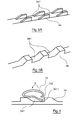
- an embodiment of a blind for a glazed roof according to the invention is presented in a partially deployed position.
- a blind comprises a concealment element 11 whose one end is provided with a draw bar 12.
- Each end of the draw bar 12 is provided with a pad 13 which slides along a fixed guide rail 14 in the frame 32 of a glazed roof 10.
- the occulting element 11 may be formed of an occultation cloth whose end is secured to a winding tube (not shown). According to a variant, it may also be a concealment element composed of one or more rigid elements forming a canopy. In this case, the draw bar can be directly formed in, or by, one of the rigid elements forming the velum.
- Such a shoe comprises a fixing lug 131 intended to cooperate with one end of the draw bar 12. It further comprises first return means comprising two upper leaf blades 132, 133. It also comprises second return means comprising two lateral springs blades 134, 135. As shown in Figure 2, the two upper leaf springs 132, 133 extend on either side of the bracket 131 and are distributed symmetrically with respect to the longitudinal axis The lateral spring blades 134, 135 also extend on either side of the fixing lug 131 and are distributed symmetrically with respect to the longitudinal axis A of the shoe 13.
- the shoe 13 is preferably made of in a plastic material having suitable sliding properties and elasticity, at least with regard to the production of spring blades. Any other suitable material may of course be used for producing the pad 13.
- FIG. 3 illustrates a sectional view of one end of a concealment device according to the invention.
- a shoe 13 is secured to each end of the draw bar 12. To this end, the bracket 131 of the shoe 13 is inserted into a housing 121 formed at each end of the draw bar 12.
- the fastening of the pads 13 the draw bar 12 may for example be reinforced by bonding or riveting the pad or by any other suitable fastening technique.
- a guide rail 31 extends along two sides 322 of the frame 32 along an axis parallel to the longitudinal axis of the vehicle. It has a fixing foot 313 which makes it possible to fix it to the frame 32, for example by means of several screws 33.
- Each rail 31 has an upper guide wall 311 and a lateral guide wall 312, as well as a curved abutment tab 314.
- the section of the rail may be substantially different, and the walls may be formed by particular areas of the rail (for example, if this section is substantially circular, however, there are upper, lower and side areas, playing the same role as the walls listed above).
- the upper guide wall 311 extends in a first plane substantially parallel to the axis defined by the rail 31 and to the axis defined by the draw bar 12.
- the lateral guide wall 312 extends in a plane substantially perpendicular to the foreground.
- the abutment 314 extends substantially parallel to the side wall 312.
- each rail 31 is made of an aluminum alloy. Other materials can of course be implemented.
- the upper spring blades 132, 133 of the pads are intended to come into contact with the upper wall 311 of the rails 31.
- the lateral spring blades 134, 135 are intended to come into contact with the side wall 312 of the rails 31.
- each leaf spring 132, 133, 134, 135 on the upper guide walls 311 and side 312 are offset from the ends of the draw bar 12. These offsets are represented by the arrows D1 and D2. They make it possible to ensure that the spring blades 132, 133, 134, 135 act correctly on the upper wall 311 and on the lateral wall 312 of the rail 31.
- a rack 34 extends on a horizontal portion 321, on each side of the frame 32, along an axis parallel to the longitudinal axis of the vehicle.
- the rack 34 has a succession of notches 341.
- the rack 34 can be made of a plastic or metal material or any other suitable material.
- FIGS. 5a and 5b illustrate two examples of profiles that the rack 34 may present. Other profiles may of course be implemented.
- the draw bar 12 has a lower extension 122.
- This lower extension 122 appears more clearly in FIG. 6.
- the lower extension 122 can be received in notches 341 of the rack 34 and abut against the vertical wall 3411 of each notch 341.
- the upper spring blades 132, 133 can take a locking position illustrated in FIG. 3. In this position, the upper spring blades 132, 133 of each shoe 13, resting on the upper guide wall 311 of each guide rail 13 , act on each end of the draw bar 12 so that the lower extension 122 of the draw bar 12 comes to be housed in a notch 341 of each rack 34. In this way, the draw bar 12 is immobilized and the occulting element 11 is properly held in a predetermined deployed position.
- the lateral spring blades 134, 135 resting on the lateral guide wall 312 of each rail 31 act on the draw bar 12 so as to compensate for the clearances that may exist between the guide rails 31 and the end of the draw bar 12.
- the upper spring blades 132, 133 can take an unlocking position so as to allow the folding or the deployment of the occulting element 11.
- the upper spring blades 132, 133 move into the unlock position when a user acts on the draw bar so as to oppose to the return force of the upper leaf blades 132, 133.
- a user can translate the draw bar 12 according to the arrow A so as to compress the upper spring blades 132, 133 along the upper guide wall 311 of each rail 31, until the extension lower 122 of the draw bar 12 is released from the notches 341 with which it cooperates.
- the user can then fold or deploy the occulting element 11 so as to place it in the folded position or in a predetermined deployed position.
- a rotation of the draw bar 12 according to the arrow B can also allow the passage of the upper spring blades 132, 133 in the unlocked position, and release the lower extension 122 of the notches 341 with which it cooperates.
- the rotation of the pulling bar according to the arrow B facilitates the deployment of the occulting element because it keeps the lower extension 122 substantially horizontally so that it slides to the surface
- the rotation may be replaced by, or combined with, a translation, or an offset, of the drawbar.
- the user After he has placed the occulting element 11 in a desired predetermined extended position (or in the folded position), the user releases the draw bar 12 so that the upper leaf blades 132, 133 pass into their position. lock and that the pull bar is properly locked again.
- the technique according to the invention described in these embodiments relates to a glazed roof concealment device. It can just as easily be applied to the concealment of a windshield, a side window, a rear window, or a luggage compartment by means of roller blinds or awnings.
- FIG. 7 illustrates a method of joining an occulting cloth 71 to the draw bar 12 by means of a bead wire 72 and a hem 73.
- FIG. 8 illustrates an example of a handle 81 making it possible to easily handle the draw bar 12.
Landscapes
- Engineering & Computer Science (AREA)
- Mechanical Engineering (AREA)
- Curtains And Furnishings For Windows Or Doors (AREA)
- Fittings On The Vehicle Exterior For Carrying Loads, And Devices For Holding Or Mounting Articles (AREA)
Applications Claiming Priority (1)
| Application Number | Priority Date | Filing Date | Title |
|---|---|---|---|
| FR0608408A FR2906188B1 (fr) | 2006-09-22 | 2006-09-22 | Dispositif d'occultation a patins equipes de moyens de rappel et vehicule correspondant |
Publications (1)
| Publication Number | Publication Date |
|---|---|
| EP1902880A1 true EP1902880A1 (de) | 2008-03-26 |
Family
ID=38042814
Family Applications (1)
| Application Number | Title | Priority Date | Filing Date |
|---|---|---|---|
| EP07117001A Withdrawn EP1902880A1 (de) | 2006-09-22 | 2007-09-21 | Abdeckungsvorrichtung mit Kufen, die mit Rückholmitteln ausgestattet sind, und entsprechendes Kraftfahrzeug |
Country Status (2)
| Country | Link |
|---|---|
| EP (1) | EP1902880A1 (de) |
| FR (1) | FR2906188B1 (de) |
Cited By (4)
| Publication number | Priority date | Publication date | Assignee | Title |
|---|---|---|---|---|
| FR2925103A1 (fr) * | 2007-12-17 | 2009-06-19 | Peugeot Citroen Automobiles Sa | Module d'occultation avec un support pour une surface vitree ou un panneau transparent, notamment pour vehicule automobile |
| FR2982534A1 (fr) * | 2011-11-16 | 2013-05-17 | Peugeot Citroen Automobiles Sa | Dispositif d'occultation d'un toit de vehicule automobile et procede de mise en oeuvre correspondant |
| CN104085279A (zh) * | 2014-07-18 | 2014-10-08 | 安徽江淮汽车股份有限公司 | 一种汽车的天窗遮阳板总成以及汽车 |
| EP3222452A1 (de) * | 2016-03-21 | 2017-09-27 | Inalfa Roof Systems Group B.V. | Gleitträgeranordnung und dachanordnung für ein fahrzeug |
Families Citing this family (1)
| Publication number | Priority date | Publication date | Assignee | Title |
|---|---|---|---|---|
| DE102011102718B4 (de) | 2011-05-20 | 2014-03-13 | Webasto Ag | Gleitereinheit zur Lagerung eines beweglichen Dachelements eines Fahrzeugdachs und Fahrzeugdach |
Citations (4)
| Publication number | Priority date | Publication date | Assignee | Title |
|---|---|---|---|---|
| EP1415836A1 (de) * | 2002-10-28 | 2004-05-06 | Webasto Vehicle Systems International GmbH | Öffnungsfähige Dachvorrichtung mit Verdunkelungsrollo |
| EP1659013A1 (de) * | 2004-11-22 | 2006-05-24 | Inalfa Roof Systems Group B.V. | Gleitschuh und damit ausgerüstete Sonnenschutzanordnung |
| WO2006053520A2 (de) * | 2004-11-19 | 2006-05-26 | Webasto Ag | Rolloanordnung für ein fahrzeug |
| FR2878889A1 (fr) * | 2004-12-06 | 2006-06-09 | Webasto Systemes Carrosserie S | Dispositif d'occultation a rideau a enrouleur notamment pour vehicule automobile |
-
2006
- 2006-09-22 FR FR0608408A patent/FR2906188B1/fr not_active Expired - Fee Related
-
2007
- 2007-09-21 EP EP07117001A patent/EP1902880A1/de not_active Withdrawn
Patent Citations (4)
| Publication number | Priority date | Publication date | Assignee | Title |
|---|---|---|---|---|
| EP1415836A1 (de) * | 2002-10-28 | 2004-05-06 | Webasto Vehicle Systems International GmbH | Öffnungsfähige Dachvorrichtung mit Verdunkelungsrollo |
| WO2006053520A2 (de) * | 2004-11-19 | 2006-05-26 | Webasto Ag | Rolloanordnung für ein fahrzeug |
| EP1659013A1 (de) * | 2004-11-22 | 2006-05-24 | Inalfa Roof Systems Group B.V. | Gleitschuh und damit ausgerüstete Sonnenschutzanordnung |
| FR2878889A1 (fr) * | 2004-12-06 | 2006-06-09 | Webasto Systemes Carrosserie S | Dispositif d'occultation a rideau a enrouleur notamment pour vehicule automobile |
Cited By (6)
| Publication number | Priority date | Publication date | Assignee | Title |
|---|---|---|---|---|
| FR2925103A1 (fr) * | 2007-12-17 | 2009-06-19 | Peugeot Citroen Automobiles Sa | Module d'occultation avec un support pour une surface vitree ou un panneau transparent, notamment pour vehicule automobile |
| FR2982534A1 (fr) * | 2011-11-16 | 2013-05-17 | Peugeot Citroen Automobiles Sa | Dispositif d'occultation d'un toit de vehicule automobile et procede de mise en oeuvre correspondant |
| CN104085279A (zh) * | 2014-07-18 | 2014-10-08 | 安徽江淮汽车股份有限公司 | 一种汽车的天窗遮阳板总成以及汽车 |
| CN104085279B (zh) * | 2014-07-18 | 2016-02-03 | 安徽江淮汽车股份有限公司 | 一种汽车的天窗遮阳板总成以及汽车 |
| EP3222452A1 (de) * | 2016-03-21 | 2017-09-27 | Inalfa Roof Systems Group B.V. | Gleitträgeranordnung und dachanordnung für ein fahrzeug |
| US9969245B2 (en) | 2016-03-21 | 2018-05-15 | Inalfa Roof Systems Group B.V. | Sliding support arrangement and roof assembly for a vehicle |
Also Published As
| Publication number | Publication date |
|---|---|
| FR2906188B1 (fr) | 2008-12-05 |
| FR2906188A1 (fr) | 2008-03-28 |
Similar Documents
| Publication | Publication Date | Title |
|---|---|---|
| FR2744967A1 (fr) | Dispositif de securite pour l'habitacle d'un vehicule automobile | |
| EP2335956B1 (de) | Abdeckvorrichtung, Fahrzeug und korrespondierendes Herstellungsverfahren | |
| EP1902880A1 (de) | Abdeckungsvorrichtung mit Kufen, die mit Rückholmitteln ausgestattet sind, und entsprechendes Kraftfahrzeug | |
| EP1914095B1 (de) | Abdeckungsvorrichtung mit Schwingarm und seitlichem Abdeckungselement sowie entsprechender Schwingarm und entsprechendes Kraftfahrzeug | |
| EP1921234A1 (de) | Verriegelungsvorrichtung mit deformierbarem Griff für Schiebeflügel, entsprechende Abdeckvorrichtung und entsprechendes Kraftfahrzeug | |
| EP1400385A1 (de) | Gepäckabdeckeinrichtung für Kraftfahrzeuge mit Heckklappe, mit automatischer Steuerung, und entsprechendes Kraftfahrzeug | |
| FR2882090A1 (fr) | Dispositif d'occultation a rideau enrouleur manuel et multi position | |
| FR2903347A1 (fr) | Store a enrouleur a support de cassette,procede d'assemblage et vehicule automobile correspondants | |
| FR2900598A1 (fr) | Dispositif d'occultation pour vehicule automobile a toiles solidarisables, et vehicule automobile correspondant. | |
| EP0741057B1 (de) | Ladagutabdeckung für eine Kraftfahrzeug | |
| EP3967531B1 (de) | Vorrichtung zur abdichtung eines in die karosserie eines fahrzeugs eingelassenen öffnungsfelds, und entsprechendes fahrzeug | |
| EP1852309A1 (de) | Gepäckabdeckungsvorrichtung für Kraftfahrzeuge mit automatischer Teilöffnung und entsprechendes Kraftfahrzeug | |
| FR2901741A1 (fr) | Dispositif d'obturation d'une baie menagee dans un vehicule automobile, a rails non paralleles et pions mobiles, et vehicule correspondant | |
| EP2017105B1 (de) | Abdeckungsrollo für Kraftfahrzeug mit Schwenkzugstange und entsprechendes Fahrzeug | |
| EP2208628B1 (de) | Vorrichtung, die den verglasten Anteil eines Kraftfahrzeugdachs bildet und mit einem Abweiser ausgestattet ist | |
| FR2882970A1 (fr) | Dispositif d'occultation pour vehicule automobile, et vehicule correspondant | |
| FR2866276A1 (fr) | Dispositif d'occultation pour vehicule automobile, et vehicule correspondant | |
| EP1852288B1 (de) | KFZ-Beschattungsvorrichtung mit klappbaren Spriegeln und dazugehöriges Fahrzeug | |
| FR2948900A1 (fr) | Dispositif d'occultation d'un element vitre d'un pavillon de vehicule | |
| EP2730463A1 (de) | Abdeckvorrichtung eines Kofferraumfachs eines Kraftfahrzeugs | |
| FR2902054A1 (fr) | Systeme de cache-bagages a elements de solidarisation ajustables, element de solidarisation, procede de montage et vehicule correspondants | |
| FR2902387A1 (fr) | Dispositif de securite en cas de retournement d'un vehicule | |
| EP1700727B1 (de) | Sonnenschutz für ein Motorfahrzeug, mit komplementärem Schutz und korrespondierendes Motorfahrzeug | |
| FR2959452A1 (fr) | Dispositif d'occultation pour vehicule automobile, et vehicule correspondant. | |
| FR2907399A1 (fr) | Dispositif de separation a deploiement et maintien automatique,et vehicule automobile correspondant |
Legal Events
| Date | Code | Title | Description |
|---|---|---|---|
| PUAI | Public reference made under article 153(3) epc to a published international application that has entered the european phase |
Free format text: ORIGINAL CODE: 0009012 |
|
| AK | Designated contracting states |
Kind code of ref document: A1 Designated state(s): AT BE BG CH CY CZ DE DK EE ES FI FR GB GR HU IE IS IT LI LT LU LV MC MT NL PL PT RO SE SI SK TR |
|
| AX | Request for extension of the european patent |
Extension state: AL BA HR MK YU |
|
| 17P | Request for examination filed |
Effective date: 20080925 |
|
| AKX | Designation fees paid |
Designated state(s): DE FR |
|
| STAA | Information on the status of an ep patent application or granted ep patent |
Free format text: STATUS: THE APPLICATION IS DEEMED TO BE WITHDRAWN |
|
| 18D | Application deemed to be withdrawn |
Effective date: 20100331 |