EP1902689A1 - Glenoid component for shoulder arthroplasty - Google Patents
Glenoid component for shoulder arthroplasty Download PDFInfo
- Publication number
- EP1902689A1 EP1902689A1 EP07253676A EP07253676A EP1902689A1 EP 1902689 A1 EP1902689 A1 EP 1902689A1 EP 07253676 A EP07253676 A EP 07253676A EP 07253676 A EP07253676 A EP 07253676A EP 1902689 A1 EP1902689 A1 EP 1902689A1
- Authority
- EP
- European Patent Office
- Prior art keywords
- triangular cross
- section
- component
- glenoid
- vertex
- Prior art date
- Legal status (The legal status is an assumption and is not a legal conclusion. Google has not performed a legal analysis and makes no representation as to the accuracy of the status listed.)
- Granted
Links
- 241001653121 Glenoides Species 0.000 title claims abstract description 107
- 238000011882 arthroplasty Methods 0.000 title claims abstract description 11
- 238000000034 method Methods 0.000 claims abstract description 19
- 210000002758 humerus Anatomy 0.000 claims description 2
- 210000000323 shoulder joint Anatomy 0.000 claims description 2
- 210000001991 scapula Anatomy 0.000 description 24
- 230000000877 morphologic effect Effects 0.000 description 8
- 210000004095 humeral head Anatomy 0.000 description 7
- 210000000988 bone and bone Anatomy 0.000 description 6
- 239000000463 material Substances 0.000 description 5
- 230000001575 pathological effect Effects 0.000 description 5
- 238000009877 rendering Methods 0.000 description 4
- 239000007787 solid Substances 0.000 description 4
- 239000004698 Polyethylene Substances 0.000 description 3
- 239000004699 Ultra-high molecular weight polyethylene Substances 0.000 description 3
- 210000003484 anatomy Anatomy 0.000 description 3
- 239000011248 coating agent Substances 0.000 description 3
- 238000000576 coating method Methods 0.000 description 3
- 239000007943 implant Substances 0.000 description 3
- 238000002513 implantation Methods 0.000 description 3
- 238000001459 lithography Methods 0.000 description 3
- -1 polyethylene Polymers 0.000 description 3
- 229920000573 polyethylene Polymers 0.000 description 3
- 229920000785 ultra high molecular weight polyethylene Polymers 0.000 description 3
- 230000001419 dependent effect Effects 0.000 description 2
- 238000010586 diagram Methods 0.000 description 2
- 230000013011 mating Effects 0.000 description 2
- 238000005259 measurement Methods 0.000 description 2
- 239000004033 plastic Substances 0.000 description 2
- 229920003023 plastic Polymers 0.000 description 2
- 239000004705 High-molecular-weight polyethylene Substances 0.000 description 1
- 229910001069 Ti alloy Inorganic materials 0.000 description 1
- WAIPAZQMEIHHTJ-UHFFFAOYSA-N [Cr].[Co] Chemical class [Cr].[Co] WAIPAZQMEIHHTJ-UHFFFAOYSA-N 0.000 description 1
- 239000000853 adhesive Substances 0.000 description 1
- 230000001070 adhesive effect Effects 0.000 description 1
- 230000003466 anti-cipated effect Effects 0.000 description 1
- 239000000560 biocompatible material Substances 0.000 description 1
- 239000002639 bone cement Substances 0.000 description 1
- 230000006835 compression Effects 0.000 description 1
- 238000007906 compression Methods 0.000 description 1
- 230000001054 cortical effect Effects 0.000 description 1
- 238000001746 injection moulding Methods 0.000 description 1
- 230000002045 lasting effect Effects 0.000 description 1
- 229910052751 metal Inorganic materials 0.000 description 1
- 239000002184 metal Substances 0.000 description 1
- 229920000642 polymer Polymers 0.000 description 1
- 238000002360 preparation method Methods 0.000 description 1
- 238000007493 shaping process Methods 0.000 description 1
- 238000004513 sizing Methods 0.000 description 1
- 229910001256 stainless steel alloy Inorganic materials 0.000 description 1
- 238000001356 surgical procedure Methods 0.000 description 1
Images


Classifications
-
- A—HUMAN NECESSITIES
- A61—MEDICAL OR VETERINARY SCIENCE; HYGIENE
- A61B—DIAGNOSIS; SURGERY; IDENTIFICATION
- A61B34/00—Computer-aided surgery; Manipulators or robots specially adapted for use in surgery
- A61B34/10—Computer-aided planning, simulation or modelling of surgical operations
-
- A—HUMAN NECESSITIES
- A61—MEDICAL OR VETERINARY SCIENCE; HYGIENE
- A61F—FILTERS IMPLANTABLE INTO BLOOD VESSELS; PROSTHESES; DEVICES PROVIDING PATENCY TO, OR PREVENTING COLLAPSING OF, TUBULAR STRUCTURES OF THE BODY, e.g. STENTS; ORTHOPAEDIC, NURSING OR CONTRACEPTIVE DEVICES; FOMENTATION; TREATMENT OR PROTECTION OF EYES OR EARS; BANDAGES, DRESSINGS OR ABSORBENT PADS; FIRST-AID KITS
- A61F2/00—Filters implantable into blood vessels; Prostheses, i.e. artificial substitutes or replacements for parts of the body; Appliances for connecting them with the body; Devices providing patency to, or preventing collapsing of, tubular structures of the body, e.g. stents
- A61F2/02—Prostheses implantable into the body
- A61F2/30—Joints
- A61F2/40—Joints for shoulders
- A61F2/4081—Glenoid components, e.g. cups
-
- G—PHYSICS
- G06—COMPUTING; CALCULATING OR COUNTING
- G06T—IMAGE DATA PROCESSING OR GENERATION, IN GENERAL
- G06T17/00—Three dimensional [3D] modelling, e.g. data description of 3D objects
-
- A—HUMAN NECESSITIES
- A61—MEDICAL OR VETERINARY SCIENCE; HYGIENE
- A61F—FILTERS IMPLANTABLE INTO BLOOD VESSELS; PROSTHESES; DEVICES PROVIDING PATENCY TO, OR PREVENTING COLLAPSING OF, TUBULAR STRUCTURES OF THE BODY, e.g. STENTS; ORTHOPAEDIC, NURSING OR CONTRACEPTIVE DEVICES; FOMENTATION; TREATMENT OR PROTECTION OF EYES OR EARS; BANDAGES, DRESSINGS OR ABSORBENT PADS; FIRST-AID KITS
- A61F2/00—Filters implantable into blood vessels; Prostheses, i.e. artificial substitutes or replacements for parts of the body; Appliances for connecting them with the body; Devices providing patency to, or preventing collapsing of, tubular structures of the body, e.g. stents
- A61F2/02—Prostheses implantable into the body
- A61F2/30—Joints
- A61F2/3094—Designing or manufacturing processes
-
- A—HUMAN NECESSITIES
- A61—MEDICAL OR VETERINARY SCIENCE; HYGIENE
- A61F—FILTERS IMPLANTABLE INTO BLOOD VESSELS; PROSTHESES; DEVICES PROVIDING PATENCY TO, OR PREVENTING COLLAPSING OF, TUBULAR STRUCTURES OF THE BODY, e.g. STENTS; ORTHOPAEDIC, NURSING OR CONTRACEPTIVE DEVICES; FOMENTATION; TREATMENT OR PROTECTION OF EYES OR EARS; BANDAGES, DRESSINGS OR ABSORBENT PADS; FIRST-AID KITS
- A61F2/00—Filters implantable into blood vessels; Prostheses, i.e. artificial substitutes or replacements for parts of the body; Appliances for connecting them with the body; Devices providing patency to, or preventing collapsing of, tubular structures of the body, e.g. stents
- A61F2/02—Prostheses implantable into the body
- A61F2/30—Joints
- A61F2002/30001—Additional features of subject-matter classified in A61F2/28, A61F2/30 and subgroups thereof
- A61F2002/30108—Shapes
- A61F2002/3011—Cross-sections or two-dimensional shapes
- A61F2002/30138—Convex polygonal shapes
- A61F2002/30156—Convex polygonal shapes triangular
-
- A—HUMAN NECESSITIES
- A61—MEDICAL OR VETERINARY SCIENCE; HYGIENE
- A61F—FILTERS IMPLANTABLE INTO BLOOD VESSELS; PROSTHESES; DEVICES PROVIDING PATENCY TO, OR PREVENTING COLLAPSING OF, TUBULAR STRUCTURES OF THE BODY, e.g. STENTS; ORTHOPAEDIC, NURSING OR CONTRACEPTIVE DEVICES; FOMENTATION; TREATMENT OR PROTECTION OF EYES OR EARS; BANDAGES, DRESSINGS OR ABSORBENT PADS; FIRST-AID KITS
- A61F2/00—Filters implantable into blood vessels; Prostheses, i.e. artificial substitutes or replacements for parts of the body; Appliances for connecting them with the body; Devices providing patency to, or preventing collapsing of, tubular structures of the body, e.g. stents
- A61F2/02—Prostheses implantable into the body
- A61F2/30—Joints
- A61F2002/30001—Additional features of subject-matter classified in A61F2/28, A61F2/30 and subgroups thereof
- A61F2002/30316—The prosthesis having different structural features at different locations within the same prosthesis; Connections between prosthetic parts; Special structural features of bone or joint prostheses not otherwise provided for
- A61F2002/30535—Special structural features of bone or joint prostheses not otherwise provided for
- A61F2002/30604—Special structural features of bone or joint prostheses not otherwise provided for modular
-
- A—HUMAN NECESSITIES
- A61—MEDICAL OR VETERINARY SCIENCE; HYGIENE
- A61F—FILTERS IMPLANTABLE INTO BLOOD VESSELS; PROSTHESES; DEVICES PROVIDING PATENCY TO, OR PREVENTING COLLAPSING OF, TUBULAR STRUCTURES OF THE BODY, e.g. STENTS; ORTHOPAEDIC, NURSING OR CONTRACEPTIVE DEVICES; FOMENTATION; TREATMENT OR PROTECTION OF EYES OR EARS; BANDAGES, DRESSINGS OR ABSORBENT PADS; FIRST-AID KITS
- A61F2/00—Filters implantable into blood vessels; Prostheses, i.e. artificial substitutes or replacements for parts of the body; Appliances for connecting them with the body; Devices providing patency to, or preventing collapsing of, tubular structures of the body, e.g. stents
- A61F2/02—Prostheses implantable into the body
- A61F2/30—Joints
- A61F2/3094—Designing or manufacturing processes
- A61F2/30942—Designing or manufacturing processes for designing or making customized prostheses, e.g. using templates, CT or NMR scans, finite-element analysis or CAD-CAM techniques
- A61F2002/30948—Designing or manufacturing processes for designing or making customized prostheses, e.g. using templates, CT or NMR scans, finite-element analysis or CAD-CAM techniques using computerized tomography, i.e. CT scans
-
- A—HUMAN NECESSITIES
- A61—MEDICAL OR VETERINARY SCIENCE; HYGIENE
- A61F—FILTERS IMPLANTABLE INTO BLOOD VESSELS; PROSTHESES; DEVICES PROVIDING PATENCY TO, OR PREVENTING COLLAPSING OF, TUBULAR STRUCTURES OF THE BODY, e.g. STENTS; ORTHOPAEDIC, NURSING OR CONTRACEPTIVE DEVICES; FOMENTATION; TREATMENT OR PROTECTION OF EYES OR EARS; BANDAGES, DRESSINGS OR ABSORBENT PADS; FIRST-AID KITS
- A61F2/00—Filters implantable into blood vessels; Prostheses, i.e. artificial substitutes or replacements for parts of the body; Appliances for connecting them with the body; Devices providing patency to, or preventing collapsing of, tubular structures of the body, e.g. stents
- A61F2/02—Prostheses implantable into the body
- A61F2/30—Joints
- A61F2/3094—Designing or manufacturing processes
- A61F2/30942—Designing or manufacturing processes for designing or making customized prostheses, e.g. using templates, CT or NMR scans, finite-element analysis or CAD-CAM techniques
- A61F2002/30952—Designing or manufacturing processes for designing or making customized prostheses, e.g. using templates, CT or NMR scans, finite-element analysis or CAD-CAM techniques using CAD-CAM techniques or NC-techniques
-
- A—HUMAN NECESSITIES
- A61—MEDICAL OR VETERINARY SCIENCE; HYGIENE
- A61F—FILTERS IMPLANTABLE INTO BLOOD VESSELS; PROSTHESES; DEVICES PROVIDING PATENCY TO, OR PREVENTING COLLAPSING OF, TUBULAR STRUCTURES OF THE BODY, e.g. STENTS; ORTHOPAEDIC, NURSING OR CONTRACEPTIVE DEVICES; FOMENTATION; TREATMENT OR PROTECTION OF EYES OR EARS; BANDAGES, DRESSINGS OR ABSORBENT PADS; FIRST-AID KITS
- A61F2/00—Filters implantable into blood vessels; Prostheses, i.e. artificial substitutes or replacements for parts of the body; Appliances for connecting them with the body; Devices providing patency to, or preventing collapsing of, tubular structures of the body, e.g. stents
- A61F2/02—Prostheses implantable into the body
- A61F2/30—Joints
- A61F2/3094—Designing or manufacturing processes
- A61F2/30942—Designing or manufacturing processes for designing or making customized prostheses, e.g. using templates, CT or NMR scans, finite-element analysis or CAD-CAM techniques
- A61F2002/30957—Designing or manufacturing processes for designing or making customized prostheses, e.g. using templates, CT or NMR scans, finite-element analysis or CAD-CAM techniques using a positive or a negative model, e.g. moulds
-
- A—HUMAN NECESSITIES
- A61—MEDICAL OR VETERINARY SCIENCE; HYGIENE
- A61F—FILTERS IMPLANTABLE INTO BLOOD VESSELS; PROSTHESES; DEVICES PROVIDING PATENCY TO, OR PREVENTING COLLAPSING OF, TUBULAR STRUCTURES OF THE BODY, e.g. STENTS; ORTHOPAEDIC, NURSING OR CONTRACEPTIVE DEVICES; FOMENTATION; TREATMENT OR PROTECTION OF EYES OR EARS; BANDAGES, DRESSINGS OR ABSORBENT PADS; FIRST-AID KITS
- A61F2/00—Filters implantable into blood vessels; Prostheses, i.e. artificial substitutes or replacements for parts of the body; Appliances for connecting them with the body; Devices providing patency to, or preventing collapsing of, tubular structures of the body, e.g. stents
- A61F2/02—Prostheses implantable into the body
- A61F2/30—Joints
- A61F2/3094—Designing or manufacturing processes
- A61F2/30942—Designing or manufacturing processes for designing or making customized prostheses, e.g. using templates, CT or NMR scans, finite-element analysis or CAD-CAM techniques
- A61F2002/30962—Designing or manufacturing processes for designing or making customized prostheses, e.g. using templates, CT or NMR scans, finite-element analysis or CAD-CAM techniques using stereolithography
-
- A—HUMAN NECESSITIES
- A61—MEDICAL OR VETERINARY SCIENCE; HYGIENE
- A61F—FILTERS IMPLANTABLE INTO BLOOD VESSELS; PROSTHESES; DEVICES PROVIDING PATENCY TO, OR PREVENTING COLLAPSING OF, TUBULAR STRUCTURES OF THE BODY, e.g. STENTS; ORTHOPAEDIC, NURSING OR CONTRACEPTIVE DEVICES; FOMENTATION; TREATMENT OR PROTECTION OF EYES OR EARS; BANDAGES, DRESSINGS OR ABSORBENT PADS; FIRST-AID KITS
- A61F2230/00—Geometry of prostheses classified in groups A61F2/00 - A61F2/26 or A61F2/82 or A61F9/00 or A61F11/00 or subgroups thereof
- A61F2230/0002—Two-dimensional shapes, e.g. cross-sections
- A61F2230/0017—Angular shapes
- A61F2230/0023—Angular shapes triangular
-
- A—HUMAN NECESSITIES
- A61—MEDICAL OR VETERINARY SCIENCE; HYGIENE
- A61F—FILTERS IMPLANTABLE INTO BLOOD VESSELS; PROSTHESES; DEVICES PROVIDING PATENCY TO, OR PREVENTING COLLAPSING OF, TUBULAR STRUCTURES OF THE BODY, e.g. STENTS; ORTHOPAEDIC, NURSING OR CONTRACEPTIVE DEVICES; FOMENTATION; TREATMENT OR PROTECTION OF EYES OR EARS; BANDAGES, DRESSINGS OR ABSORBENT PADS; FIRST-AID KITS
- A61F2240/00—Manufacturing or designing of prostheses classified in groups A61F2/00 - A61F2/26 or A61F2/82 or A61F9/00 or A61F11/00 or subgroups thereof
- A61F2240/001—Designing or manufacturing processes
- A61F2240/002—Designing or making customized prostheses
-
- B—PERFORMING OPERATIONS; TRANSPORTING
- B33—ADDITIVE MANUFACTURING TECHNOLOGY
- B33Y—ADDITIVE MANUFACTURING, i.e. MANUFACTURING OF THREE-DIMENSIONAL [3-D] OBJECTS BY ADDITIVE DEPOSITION, ADDITIVE AGGLOMERATION OR ADDITIVE LAYERING, e.g. BY 3-D PRINTING, STEREOLITHOGRAPHY OR SELECTIVE LASER SINTERING
- B33Y80/00—Products made by additive manufacturing
-
- Y—GENERAL TAGGING OF NEW TECHNOLOGICAL DEVELOPMENTS; GENERAL TAGGING OF CROSS-SECTIONAL TECHNOLOGIES SPANNING OVER SEVERAL SECTIONS OF THE IPC; TECHNICAL SUBJECTS COVERED BY FORMER USPC CROSS-REFERENCE ART COLLECTIONS [XRACs] AND DIGESTS
- Y10—TECHNICAL SUBJECTS COVERED BY FORMER USPC
- Y10T—TECHNICAL SUBJECTS COVERED BY FORMER US CLASSIFICATION
- Y10T29/00—Metal working
- Y10T29/49—Method of mechanical manufacture
Definitions
- This present invention relates to glenoid components for shoulder arthroplasty and methods for making them.
- Arthroplasty is the surgical replacement of one or more bone structures of a joint with one or more prostheses. Shoulder arthroplasty often involves replacement of the glenoid fossa of the scapula with a prosthetic glenoid component.
- the conventional glenoid component typically provides a generally laterally or outwardly facing generally concave bearing surface against which a prosthetic humeral head (or, alternatively, the spared natural humeral head in the case of a glenoid hemi-arthroplasty) may bear during operation of the joint.
- the conventional glenoid component typically also includes a generally medially or inwardly projecting stem for fixing the glenoid component in a cavity constructed by suitably resecting the glenoid fossa and suitably resecting cancellous bone from the glenoid vault.
- a glenoid component is fitted to at least partially fill a cavity formed in the glenoid vault.
- the component has a generally oval inverted dome shape to generally conform to the shape of the vault.
- exact sizing of the glenoid component to the vault cavity is made difficult by the unique anatomy of each patient.
- a series of differently sized glenoid components is provided.
- This invention provides a glenoid component that is more nearly sized and shaped in three-dimensions to fill the cavity in the glenoid vault. It also provides a technique which facilitates preparation of such a component, and especially a component that has more universal applicability to the anatomy of most patients.
- the invention provides a glenoid component for shoulder arthroplasty.
- the component has a bearing portion and further includes a stem portion extending from the bearing portion.
- the stem portion models a normalized or pathologic glenoid vault morphology.
- the invention provides a method for making a glenoid component for shoulder arthroplasty.
- the method includes obtaining a model of a normal or pathologic glenoid vault morphology and further includes producing a portion of the glenoid component based on the model.
- the invention provides a glenoid component for a shoulder joint including at least one of a natural humeral component and a prosthetic humeral component.
- the component includes a means for bearing against at least one of the natural humeral component and the prosthetic humeral component.
- the component further includes a means, extending from the bearing means, for modeling a normal glenoid vault morphology.
- FIG. 1 shows an exploded perspective view of an exemplary shoulder prosthesis 100 including an exemplary glenoid component 120 according to the present invention.
- Prosthesis 100 also includes an exemplary humeral component 140.
- Humeral component 140 is configured in a known manner for implantation in a humerus 160 and replacement of a natural humeral head (not shown) and, accordingly, includes a prosthetic humeral head 180.
- Glenoid component 120 is configured for implantation in a scapula 200 and replacement of a natural glenoid fossa (not shown in FIG. 1).
- Glenoid component 120 includes a bearing 220.
- Bearing 220 is made from a durable biocompatible plastic or any other suitable durable biocompatible material.
- bearing 220 may be made from a polyethylene.
- One particular polyethylene that is well suited for bearing 220 is a high molecular weight polyethylene, for example ultra-high molecular weight polyethylene (“UHMWPE").
- UHMWPE ultra-high molecular weight polyethylene
- a suitable polymer is disclosed in US-6228900 and US-6281264 .
- the bearing 220 includes a generally concave surface 240 that is configured as known for bearing against prosthetic humeral head 180 or, in cases where the natural humeral head is spared, for bearing against the natural humeral head.
- the bearing 220 further includes a post 260, or some other feature or mechanism capable of mating the bearing to a stem element of the glenoid component, such as stem 280 discussed below.
- the glenoid component 120 also includes a stem 280.
- the stem 280 is configured to model a normal or pathologic glenoid vault morphology such that the stem 280 fits within a cavity 300 that may be defined, at least partially, by endosteal walls 320 of scapula 200.
- the present invention may provide a series of rigidly scaled or sized versions of stem 280 for accommodating various glenoid vault sizes that may be presented among different patients.
- the glenoid vault of scapula 200 may include some cancellous bone 340.
- Stem 280 is made from a suitable biocompatible metal such as, for example, a cobalt chromium alloy, a stainless steel alloy, a titanium alloy, or any other suitable durable material.
- stem 280 may include a porous coating to facilitate bone in-growth into glenoid component 120.
- the porous coating may be any suitable porous coating, for example of the kind which is disclosed in US-3855638 .
- Stem 280 can be solid or a thin shell of suitable durable material.
- Stem 280 includes a generally superior surface 360, a generally inferior surface 380, a generally anterior-medial surface 400, a generally posterior-medial surface 420, and a generally lateral surface 440.
- Stem 280 defines a socket 460 that extends inwardly from surface 440. Socket 460 receives post 260 (of bearing 220).
- Stem 280 may also define a through-channel 480 that extends, coaxially with socket 460, through stem 280.
- Glenoid component 120 further includes a fastener 500 in the form of, for example, a screw.
- the screw, or screws may be any screw capable of additionally securing glenoid component 120 within scapula 200.
- the screw may be a cortical screw such as the one which is available from DePuy Orthopaedics Inc under the trade mark DePuy Ace, catalogue number 8150-36-030.
- the screw has a diameter sufficient to properly secure glenoid component 120 within scapula 200 and may, for example, have a diameter of about 2 to 5 mm.
- the screw may have any suitable length capable of properly securing glenoid component 120 within scapula 200.
- the screw may have a length of from 10 to 60 mm.
- the screw may be secured to stem 280 in any suitable manner.
- fastener 500 extends through through-channel 480 (of stem 280). However, it is noted that fastener 500 may be omitted from alternative embodiments.
- Bearing 220 is secured to stem 280 in any suitable manner.
- bearing 220 may be bonded to stem 280, or bearing 220 could be made from polyethylene and compression molded to stem 280.
- the bearing 220 may be glued to stem 280 by, for example, an adhesive.
- bearing 220 may be mechanically interlocked to stem 280 by taper locking or otherwise press-fitting post 260 in socket 460, or post 260 and socket 460 may include any other suitable interlocking features, for example, rib(s), lip(s), detent(s), and/or other protrusion(s) and mating groove(s), channel(s), or indent(s) (not shown).
- bearing 220 and stem 280 may be integrated into a single part made from UHMWPE or any other suitable material, with or without an omission of fastener 500.
- the present invention contemplates a method for preparing a glenoid component that will satisfy a majority of patient anatomies.
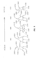
- the steps described in flow diagrams of FIGS. 2a to 2c correspond to one exemplary method used to model the normal or pathologic glenoid vault morphology, and ultimately to prepare an optimally sized and configured implant.
- a suitable sample of human scapulae (“scapulae sample”) is selected to represent a reasonable demographic cross section of an anticipated patient population.
- the scapulae sample included 61 human scapulae selected from different sources, 33 left-sided and 28 right-sided.
- Various criteria were applied to the selection process so that the sample was as representative of the patient population as possible, including height, sex, gender and ethnicity.
- volumetric scan of each scapula in the sample was performed using a Siemens Volume Zoom Scanner (a CT scanner available from Siemens Medical Systems of Malvern, Pennsylvania). It is noted that the initial orientation of the scapulae in the CT images is dependent on the physical placement and orientation of the scapulae within the CT scanner, which is inherently difficult to reproduce. Nevertheless, the scapulae were placed in a supine anatomic position and axial images were obtained in one mm increments (with 0.27 to 0.35 mm in-plane resolution). The images were acquired at 120 kV, 100 mA, using a 180 mm field-of-view, large focal spot, and rotation speed of 0.5 sec.rev -1 . A medium-smooth reconstruction algorithm was used for reconstruction of the images.
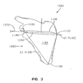
- FIG. 3 shows a rectangular (“Cartesian”) coordinates reference system 1060 relative to the plane body of a typical scapula 1080 as defined by three surface points 1100, 1120, and 1140 of the scapula 1080.
- point 1100 represents an inferior tip of the scapula 1080
- point 1120 represents a medial pole of the scapula 1080 where the spine intersects the scapula 1080
- point 1140 represents the center of the typical glenoid fossa 1160.
- coordinates reference system 1060 defines, among other things, an XZ-plane 1180, an XY-plane 1190, a vector 1200 extending from the medial pole of the scapula to the center of the glenoid fossa 1160, and an X-axis 1220.
- step 1230 the three-dimensional (“3-D") images of the scapulae were re-sampled to align them on coordinates reference system 1060 (see FIG. 3) for subsequent analysis.
- points 1100, 1120, and 1140 were interactively chosen on the 3-D image of each scapula and the scapulae were again re-sampled such that the plane of the body of each scapula was aligned parallel to the XZ-plane 1180 of the coordinates reference system 1060 (see FIG. 3), and such that the vector 1200 extending from the medial pole of the scapula to the center of the glenoid fossa 1160 was parallel to the X-axis 1220 (see FIG. 3).
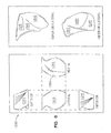
- FIG. 4 shows the superior-inferior (“SI”) dimension 1240 and the anterior-posterior (“AP”) dimension 1260 of the glenoid fossa 1160.
- SI dimension 1240 and the AP dimension 1260 were determined by interactively placing points on the 3-D images using a suitable software program.
- the scapulae sample were arbitrarily divided into six sub-groups based on their SI dimensions 1240 (see FIG. 4) to reduce the initial number of morphological comparisons and to facilitate determination of the relationship between the global or overall typical glenoid vault size and the typical glenoid vault morphology.
- FIG. 5 shows a table listing exemplary range and exemplary average SI dimension for the six sub-groups of scapulae based on their SI dimensions.
- FIG. 6 shows a substantially complete tracing 1320 (toward the inferior end of the typical glenoid fossa 1160) of the endosteal walls 320 of the typical glenoid fossa 1160.
- FIG. 7 shows a partial tracing 1360 (toward the inferior end of the typical glenoid fossa 1160) of the endosteal walls 320 of the typical glenoid fossa 1160 as a result of fossa occlusion in the region of the typical scapular spine 1380.
- Reference line 1400 (FIG.
- Each endosteal boundary was traced on each of the two-dimensional ("2-D") XY-slices of the respective re-sampled image (see FIG. 6), starting at the respective glenoid fossa and extending medially to the scapular spine 1380 (see FIG. 7), but not into the interior of the spine.
- Both the anterior and posterior wall tracings in the region of the spine are terminated at reference line 1400 (see FIG. 7), which was defined to be simultaneously perpendicular to the plane of the respective glenoid fossa and tangential to the surface of the respective endosteal notch.
- each endosteal tracing defining the respective glenoid vault was normalized by its extent in the SI dimension. This measurement was made from the inferior limit of the endosteal walls of the glenoid fossa to the superior limit in the Z-dimension (see FIG. 3) of the image.
- the vaults were rigidly scaled in all three dimensions (i.e., X, Y, and Z) to normalize the SI dimension of the vault tracing to the average within its corresponding sub-grouping. This approach substantially eliminated size differences between the different vaults, facilitating an appropriate shape determination. An assumption was made that right-sided and left-sided scapulae are approximately anatomically symmetrical.
- the normalized vaults within each of the six scapular sub-groupings were spatially aligned (i.e., "registered") using an iterative closet point (“ICP") algorithm such as discussed in Besl P J and McKay N D, "A method for registration of 3-D shapes," IEEE Trans. Pattern Analysis and Machine Intelligence 1992, volume 14, pages 239-256 .
- ICP iterative closet point
- a 3-D model of the normalized glenoid vault morphology was then constructed for each sub-group of the scapulae of the scapulae sample based on the morphological constraints imposed by each of the vaults in the sub-group.
- the set of registered glenoid vaults were overlaid and the approximate average endosteal walls 320 (see FIG. 6 and FIG. 7) of the sub-group were manually digitized.
- Each endosteal boundary was traced on each of the two-dimensional ("2-D") XY-slices of the respective re-sampled image (see FIG.
- a relatively complex 3-D model 1500 (see FIG. 8) approximating the average normalized glenoid vault morphology of the entire scapulae sample was constructed based on the morphological constraints imposed by the models for each sub-group.
- the registered glenoid vaults for the sub-groups were overlaid and the approximate average endosteal walls 320 (see FIG. 6 and FIG. 7) of the sub-group models were manually digitized.
- Each endosteal boundary was again traced on each of the two-dimensional ("2-D") XY-slices of the respective re-sampled image (see FIG.
- FIG. 8 shows views of a volumetric rendering of the relatively complex 3-D model 1500 generated in the previous steps.
- model 1500 includes a generally superior surface 1520, a generally inferior surface 1540, a generally anterior-medial surface 1560, a generally posterior-medial surface 1580, and a generally lateral surface 1600.
- generally superior surface 360 corresponds roughly to generally superior surface 1520
- generally inferior surface 380 corresponds roughly to generally inferior surface 1540
- generally anterior-medial surface 400 corresponds roughly to generally anterior-medial surface 1560
- generally posterior-medial surface 420 corresponds roughly to generally posterior-medial surface 1580
- generally lateral surface 440 corresponds roughly to generally lateral surface 1600.
- intermediate 3-D model 1700 was constructed by inscribing a plurality of mutually parallel triangular cross sections within the boundaries defined by the model walls on a plurality of XY-plane (see FIG. 3) cross-sections of relatively complex 3-D model 1500 (see FIG. 8).
- FIG. 9 shows views of a volumetric rendering of this intermediate 3-D model 1700 of the normalized glenoid vault morphology of the scapulae sample based on relatively complex 3-D model 1500 (see FIG. 8).
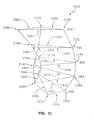
- a simplified 3-D model 1820 (see FIG. 10) of the average normalized glenoid vault morphology of the scapulae sample was constructed by selecting five equidistantly inferior-superior spaced-apart mutually parallel triangular cross sections (1840, 1860, 1880, 1900, 1920) (see FIGS. 10 and 11) from intermediate 3-D model 1700 (see FIG. 9). These triangular cross-sections were selected to account for more than 90% of the volume of intermediate 3-D model 1700 with almost negligible spatial deviation of the anterior and posterior walls. It should be appreciated that simplified 3-D model 1820 thus provides a concise geometrical model of the normalized glenoid vault morphology while substantially preserving the morphological nuances inherent to the endosteal walls 320 (see FIG. 1).
- FIG. 11 shows a superior view of each of the triangular cross sections (1840, 1860, 1880, 1900, 1920) obtained from the simplified 3-D model 1820.
- cross section 1840 includes a generally medially positioned vertex 2000, a generally anteriorly and generally laterally positioned vertex 2020, and a generally posteriorly and generally laterally positioned vertex 2040.
- cross section 1860 includes a generally medially positioned vertex 2060, a generally anteriorly and generally laterally positioned vertex 2080, and a generally posteriorly and generally laterally positioned vertex 2100.
- Cross section 1880 includes a generally medially positioned vertex 2120, a generally anteriorly and generally laterally positioned vertex 2140, and a generally posteriorly and generally laterally positioned vertex 2160.
- the next cross section 1900 includes a generally medially positioned vertex 2180, a generally anteriorly and generally laterally positioned vertex 2200, and a generally posteriorly and generally laterally positioned vertex 2220.
- cross section 1920 includes a generally medially positioned vertex 2240, a generally anteriorly and generally laterally positioned vertex 2260, and a generally posteriorly and generally laterally positioned vertex 2280.
- cross section 1840 includes a "base” edge 2400 extending between vertex 2020 and vertex 2040
- cross section 1860 includes a “base” edge 2420 extending between vertex 2080 and vertex 2100
- cross section 1880 includes a “base” edge 2440 extending between vertex 2140 and vertex 2160
- cross section 1900 includes a "base” edge 2460 extending between vertex 2200 and vertex 2220
- cross section 1920 includes a "base” edge 2680 extending between vertex 2240 and vertex 2280.
- cross section 1840 includes a "left" edge 2500 extending between vertex 2000 and vertex 2020
- cross section 1860 includes a “left” edge 2520 extending between vertex 2060 and vertex 2080
- cross section 1880 includes a "left” edge 2540 extending between vertex 2120 and vertex 2140
- cross section 1900 includes a "left” edge 2560 extending between vertex 2180 and vertex 2200
- cross section 1920 includes a "left” edge 2580 extending between vertex 2240 and vertex 2260.
- cross section 1840 includes a "right” edge 2600 extending between vertex 2000 and vertex 2040
- cross section 1860 includes a “right” edge 2620 extending between vertex 2060 and vertex 2100
- cross section 1880 includes a “right” edge 2640 extending between vertex 2120 and vertex 2160
- cross section 1900 includes a "right” edge 2660 extending between vertex 2180 and vertex 2220
- cross section 1920 includes a "right” edge 2480 extending between vertex 2260 and vertex 2280.
- the respective base edges (2400, 2420, 2440, 2460, 2680) of the triangular cross sections (1840, 1860, 1880, 1900, 1920) define lateral boundaries of simplified 3-D model 1820, corresponding to the region of the typical glenoid fossa 1160 (see FIG. 3). Further, the respective left edges (2500, 2520, 2540, 2560, 2580) of triangular cross sections (1840, 1860, 1880, 1900, 1920) define anterior boundaries of simplified 3-D model 1820, while the respective "right" edges (2600, 2620, 2640, 2660, 2480) of triangular cross sections (1840, 1860, 1880, 1900, 1920) define posterior boundaries of simplified 3-D model 1820.
- the respective generally medially positioned vertexes (2000, 2060, 2120, 2180, 2260) of triangular cross sections (1840, 1860, 1880, 1900, 1920) sweep from a more posterior orientation at the inferior end of simplified 3-D model 1820 to a more anterior orientation at the superior end of simplified 3-D model 1820.
- Each of the triangular cross sections (1840, 1860, 1880, 1900, 1920) has a respective width dimension ("w") and a depth dimension ("d”).
- the table in FIG. 12 summarizes the respective width dimension ("w") (see FIG. 11), depth dimension ("d") (see FIG. 11), and resulting area of triangular cross sections (1840, 1860, 1880, 1900, 1920).
- the table in FIG. 13 lists the coordinates for the respective vertexes of triangular cross sections (1840, 1860, 1880, 1900, 1920) relative to rectangular (“Cartesian") coordinates reference system 1060 (see FIG. 3).
- simplified 3-D model 1820 may be rigidly scaled according to SI size (see FIG. 4) to accommodate larger or smaller glenoid vaults while maintaining the integrity of the basic morphological model.
- stem 280 is initially fashioned in the shape of the simplified 3-D model 1820.
- this step 3000 contemplates loading the coordinates of each of the vertexes defining the simplified 3-D geometrical model 1820 into a suitable stereo lithography system.
- the stereo lithography system may be operated to produce a corresponding 3-D form made of a plastic, wax, or any other suitable material as is known in the art.
- a mold is then prepared from the 3-D form and a stem 280 is fashioned, such as by injection molding using this mold.
- stem 280 may be otherwise suitably produced in accordance with simplified 3-D model 1820 via stereo lithography, by hand, or by any other suitable method (with or without an intervening form or mold) as known.
- the stem 280 is machined to provide the features necessary to prepare the stem for implantation.
- socket 460 is bored into stem 280.
- through-channel 480 is bored (coaxially with socket 460) through stem 280.
- the rough stem produced from the 3-D model may be machined according to other protocols depending upon the interface between the stem 280 and the bearing 220.
- the stem 280 may be formed as a solid or a hollow body and may further be provided with certain surface features to facilitate fixation of the stem within the glenoid vault.
- cancellous bone 340 may first be removed from the glenoid vault of scapula 200 to construct cavity 300, which extends to endosteal walls 320 (see FIG. 1).
- Stem 280 is then inserted into cavity 300 into intimate contact with endosteal walls 320 to facilitate alignment and reliable fixation of glenoid component 120 within scapula 200.
- Bone cement may be used to enhance fixation of the stem within the bone.
- Fastener 480 is inserted through through-channel 480 into engagement with scapula 200. After fastener 480 is fully inserted into scapula 200, post 260 is inserted into socket 460 and bearing 220 is secured to stem 280.
- the glenoid components may be solid or hollow bodies.
- the stem 280 may be formed as a solid implant, but may be preferably at least partially hollow to reduce the weight and material requirements for the component. If the implant component is hollow, it must have sufficient wall thickness to maintain its strength and integrity under maximum expected physiological loads.
- the glenoid stem component of the invention can be is formed to approximate closely a normalized glenoid vault morphology.
- this normalized morphology is generated from a relatively large sample size of human scapulae from which relevant measurements were obtained. It was found that the normalized component dimensions obtained in accordance with the invention well approximated the actual dimensions of the sample population. In particular, it was found that at least 85% of the surface points of the sampled glenoid vaults varied by less than 2.0 mm, which represents a minimal variation given the overall dimensions of the endosteal walls of the vault.
- a morphological model is developed for several discrete groups of glenoid sizes.
- the groups may be preferably grouped by SI (superior-inferior) dimension, as summarized in the table of FIG. 5.
- SI superiorior-inferior
- the simplified model used to create the component mold in the illustrated embodiment corresponded to Group 4, but it is understood that the simplified model for the other groups may be obtained by directly scaling the dimensions as a function of the ratio of SI values.
Landscapes
- Health & Medical Sciences (AREA)
- Engineering & Computer Science (AREA)
- Life Sciences & Earth Sciences (AREA)
- Public Health (AREA)
- General Health & Medical Sciences (AREA)
- Biomedical Technology (AREA)
- Heart & Thoracic Surgery (AREA)
- Surgery (AREA)
- Veterinary Medicine (AREA)
- Animal Behavior & Ethology (AREA)
- Physics & Mathematics (AREA)
- Cardiology (AREA)
- Molecular Biology (AREA)
- Transplantation (AREA)
- Nuclear Medicine, Radiotherapy & Molecular Imaging (AREA)
- Robotics (AREA)
- Vascular Medicine (AREA)
- Medical Informatics (AREA)
- Orthopedic Medicine & Surgery (AREA)
- Oral & Maxillofacial Surgery (AREA)
- Computer Graphics (AREA)
- Geometry (AREA)
- Software Systems (AREA)
- General Physics & Mathematics (AREA)
- Theoretical Computer Science (AREA)
- Prostheses (AREA)
Abstract
Description
- This present invention relates to glenoid components for shoulder arthroplasty and methods for making them.
- Arthroplasty is the surgical replacement of one or more bone structures of a joint with one or more prostheses. Shoulder arthroplasty often involves replacement of the glenoid fossa of the scapula with a prosthetic glenoid component. The conventional glenoid component typically provides a generally laterally or outwardly facing generally concave bearing surface against which a prosthetic humeral head (or, alternatively, the spared natural humeral head in the case of a glenoid hemi-arthroplasty) may bear during operation of the joint. The conventional glenoid component typically also includes a generally medially or inwardly projecting stem for fixing the glenoid component in a cavity constructed by suitably resecting the glenoid fossa and suitably resecting cancellous bone from the glenoid vault.
- Various stem designs have been proposed for ensuring proper alignment and secure and lasting fixation of the glenoid component within the glenoid vault. However, the glenoid vault has a complex morphology. While three-dimensionally shaping a stem for compatibility with the endosteal walls of the glenoid vault can potentially significantly enhance fixation of the glenoid component, historical designs have not taken full advantage of this opportunity.
- One advantageous approach is disclosed in
US-A-2004/0064189 . In this approach, a glenoid component is fitted to at least partially fill a cavity formed in the glenoid vault. The component has a generally oval inverted dome shape to generally conform to the shape of the vault. However, it is acknowledged in this document that exact sizing of the glenoid component to the vault cavity is made difficult by the unique anatomy of each patient. To address this difficulty, it is suggested that a series of differently sized glenoid components is provided. - This invention provides a glenoid component that is more nearly sized and shaped in three-dimensions to fill the cavity in the glenoid vault. It also provides a technique which facilitates preparation of such a component, and especially a component that has more universal applicability to the anatomy of most patients.
- Accordingly, in one aspect, the invention provides a glenoid component for shoulder arthroplasty. The component has a bearing portion and further includes a stem portion extending from the bearing portion. The stem portion models a normalized or pathologic glenoid vault morphology.
- In another aspect, the invention provides a method for making a glenoid component for shoulder arthroplasty. The method includes obtaining a model of a normal or pathologic glenoid vault morphology and further includes producing a portion of the glenoid component based on the model.
- In a further aspect, the invention provides a glenoid component for a shoulder joint including at least one of a natural humeral component and a prosthetic humeral component. The component includes a means for bearing against at least one of the natural humeral component and the prosthetic humeral component. The component further includes a means, extending from the bearing means, for modeling a normal glenoid vault morphology.
- Embodiments of the intention are described below by way of example with reference to the accompanying drawings, in which:
- FIG. 1 shows an exploded perspective view of a shoulder prosthesis including a glenoid component according to the present invention;
- FIG. 2a, FIG. 2b, and FIG. 2c show a flow diagram of a method for configuring the stem of the prosthesis of FIG. 1 to model a normal or pathologic glenoid vault morphology;
- FIG. 3 shows a rectangular ("Cartesian") coordinates reference system relative to the plane body of a typical scapula as defined by three surface points of the scapula;
- FIG. 4 shows the superior-inferior ("SI") dimension and the anterior-posterior ("AP") dimension of the typical glenoid fossa;
- FIG. 5 shows a table listing range and average SI dimension for six sub-groups of scapulae from a scapulae sample based on their SI dimensions;
- FIG. 6 shows a substantially complete tracing (toward the inferior end of the typical glenoid fossa) of the endosteal walls of the typical glenoid fossa;
- FIG. 7 shows a partial tracing (toward the inferior end of the typical glenoid fossa) of the endosteal walls of the typical glenoid fossa as a result of fossa occlusion in the region of the typical scapular spine;
- FIG. 8 shows views of a volumetric rendering of a relatively complex model of the normal glenoid vault morphology of the scapulae sample;
- FIG. 9 shows views of a volumetric rendering of an intermediate 3-D model of the normal glenoid vault morphology of the scapulae sample based on the relatively complex 3-D model of FIG. 8;
- FIG. 10 shows a perspective view of a simplified 3-D model of the average normal glenoid vault morphology of the scapulae sample based on the intermediate 3-D model of FIG. 9;
- FIG. 11 shows a superior view of each of the triangular cross sections of the simplified 3-D model of FIG. 10;
- FIG. 12 shows a table listing the respective width dimension, depth dimension, and resulting area of the triangular cross sections of the simplified 3-D model of FIG. 10; and
- FIG. 13 shows a table listing the coordinates for the respective vertexes of the triangular cross sections of the simplified 3-D model of FIG. 10 relative to the rectangular ("Cartesian") coordinates reference system of FIG. 3.
- Referring to the drawings, FIG. 1 shows an exploded perspective view of an
exemplary shoulder prosthesis 100 including anexemplary glenoid component 120 according to the present invention.Prosthesis 100 also includes an exemplaryhumeral component 140.Humeral component 140 is configured in a known manner for implantation in ahumerus 160 and replacement of a natural humeral head (not shown) and, accordingly, includes a prosthetichumeral head 180. - Glenoid
component 120 is configured for implantation in ascapula 200 and replacement of a natural glenoid fossa (not shown in FIG. 1). Glenoidcomponent 120 includes abearing 220. Bearing 220 is made from a durable biocompatible plastic or any other suitable durable biocompatible material. For example, bearing 220 may be made from a polyethylene. One particular polyethylene that is well suited for bearing 220 is a high molecular weight polyethylene, for example ultra-high molecular weight polyethylene ("UHMWPE"). A suitable polymer is disclosed inUS-6228900 andUS-6281264 . Thebearing 220 includes a generallyconcave surface 240 that is configured as known for bearing against prosthetichumeral head 180 or, in cases where the natural humeral head is spared, for bearing against the natural humeral head. Thebearing 220 further includes apost 260, or some other feature or mechanism capable of mating the bearing to a stem element of the glenoid component, such asstem 280 discussed below. - The
glenoid component 120 also includes astem 280. As discussed further below, thestem 280 is configured to model a normal or pathologic glenoid vault morphology such that thestem 280 fits within acavity 300 that may be defined, at least partially, byendosteal walls 320 ofscapula 200. To this end, it is noted that the present invention may provide a series of rigidly scaled or sized versions ofstem 280 for accommodating various glenoid vault sizes that may be presented among different patients. It should also be appreciated that the glenoid vault ofscapula 200 may include somecancellous bone 340. -
Stem 280 is made from a suitable biocompatible metal such as, for example, a cobalt chromium alloy, a stainless steel alloy, a titanium alloy, or any other suitable durable material. In alternative embodiments,stem 280 may include a porous coating to facilitate bone in-growth intoglenoid component 120. The porous coating may be any suitable porous coating, for example of the kind which is disclosed inUS-3855638 .Stem 280 can be solid or a thin shell of suitable durable material. -
Stem 280 includes a generallysuperior surface 360, a generallyinferior surface 380, a generally anterior-medial surface 400, a generally posterior-medial surface 420, and a generallylateral surface 440.Stem 280 defines asocket 460 that extends inwardly fromsurface 440.Socket 460 receives post 260 (of bearing 220).Stem 280 may also define a through-channel 480 that extends, coaxially withsocket 460, throughstem 280. - Glenoid
component 120 further includes afastener 500 in the form of, for example, a screw. The screw, or screws, may be any screw capable of additionally securingglenoid component 120 withinscapula 200. For example, the screw may be a cortical screw such as the one which is available from DePuy Orthopaedics Inc under the trade mark DePuy Ace, catalogue number 8150-36-030. The screw has a diameter sufficient to properly secureglenoid component 120 withinscapula 200 and may, for example, have a diameter of about 2 to 5 mm. The screw may have any suitable length capable of properly securingglenoid component 120 withinscapula 200. For example, the screw may have a length of from 10 to 60 mm. The screw may be secured to stem 280 in any suitable manner. In the exemplary embodiment,fastener 500 extends through through-channel 480 (of stem 280). However, it is noted thatfastener 500 may be omitted from alternative embodiments. - Bearing 220 is secured to stem 280 in any suitable manner. For example, bearing 220 may be bonded to stem 280, or bearing 220 could be made from polyethylene and compression molded to stem 280. Alternately, the
bearing 220 may be glued to stem 280 by, for example, an adhesive. Alternatively, bearing 220 may be mechanically interlocked to stem 280 by taper locking or otherwise press-fittingpost 260 insocket 460, or post 260 andsocket 460 may include any other suitable interlocking features, for example, rib(s), lip(s), detent(s), and/or other protrusion(s) and mating groove(s), channel(s), or indent(s) (not shown). Additionally, it is noted that in alternative embodiments, bearing 220 and stem 280 may be integrated into a single part made from UHMWPE or any other suitable material, with or without an omission offastener 500. - The present invention contemplates a method for preparing a glenoid component that will satisfy a majority of patient anatomies. Thus, in accordance with one method, the steps described in flow diagrams of FIGS. 2a to 2c correspond to one exemplary method used to model the normal or pathologic glenoid vault morphology, and ultimately to prepare an optimally sized and configured implant.
- In a first step 1020 (FIG. 2a), a suitable sample of human scapulae ("scapulae sample") is selected to represent a reasonable demographic cross section of an anticipated patient population. In the exemplary embodiment, the scapulae sample included 61 human scapulae selected from different sources, 33 left-sided and 28 right-sided. Various criteria were applied to the selection process so that the sample was as representative of the patient population as possible, including height, sex, gender and ethnicity.
- At step 1040 (FIG. 2a), volumetric scan of each scapula in the sample was performed using a Siemens Volume Zoom Scanner (a CT scanner available from Siemens Medical Systems of Malvern, Pennsylvania). It is noted that the initial orientation of the scapulae in the CT images is dependent on the physical placement and orientation of the scapulae within the CT scanner, which is inherently difficult to reproduce. Nevertheless, the scapulae were placed in a supine anatomic position and axial images were obtained in one mm increments (with 0.27 to 0.35 mm in-plane resolution). The images were acquired at 120 kV, 100 mA, using a 180 mm field-of-view, large focal spot, and rotation speed of 0.5 sec.rev-1. A medium-smooth reconstruction algorithm was used for reconstruction of the images.
- FIG. 3 shows a rectangular ("Cartesian") coordinates
reference system 1060 relative to the plane body of atypical scapula 1080 as defined by threesurface points scapula 1080. As at least partially discernable from FIG. 3,point 1100 represents an inferior tip of thescapula 1080,point 1120 represents a medial pole of thescapula 1080 where the spine intersects thescapula 1080, andpoint 1140 represents the center of thetypical glenoid fossa 1160. Further, it should be appreciated that coordinatesreference system 1060 defines, among other things, an XZ-plane 1180, an XY-plane 1190, avector 1200 extending from the medial pole of the scapula to the center of theglenoid fossa 1160, and anX-axis 1220. - At step 1230 (FIG. 2a), the three-dimensional ("3-D") images of the scapulae were re-sampled to align them on coordinates reference system 1060 (see FIG. 3) for subsequent analysis. In the exemplary embodiment, points 1100, 1120, and 1140 were interactively chosen on the 3-D image of each scapula and the scapulae were again re-sampled such that the plane of the body of each scapula was aligned parallel to the XZ-
plane 1180 of the coordinates reference system 1060 (see FIG. 3), and such that thevector 1200 extending from the medial pole of the scapula to the center of theglenoid fossa 1160 was parallel to the X-axis 1220 (see FIG. 3). - FIG. 4 shows the superior-inferior ("SI")
dimension 1240 and the anterior-posterior ("AP")dimension 1260 of theglenoid fossa 1160. At step 1280 (FIG. 2a), theSI dimension 1240 and the AP dimension 1260 (see FIG. 4) of each scapula was determined by interactively placing points on the 3-D images using a suitable software program. - At step 1300 (FIG. 2a), the scapulae sample were arbitrarily divided into six sub-groups based on their SI dimensions 1240 (see FIG. 4) to reduce the initial number of morphological comparisons and to facilitate determination of the relationship between the global or overall typical glenoid vault size and the typical glenoid vault morphology. FIG. 5 shows a table listing exemplary range and exemplary average SI dimension for the six sub-groups of scapulae based on their SI dimensions.
- At step 1420 (FIG. 2a), the
endosteal walls 320 of the glenoid vaults of the scapulae were manually traced and digitized. FIG. 6 shows a substantially complete tracing 1320 (toward the inferior end of the typical glenoid fossa 1160) of theendosteal walls 320 of thetypical glenoid fossa 1160. FIG. 7 shows a partial tracing 1360 (toward the inferior end of the typical glenoid fossa 1160) of theendosteal walls 320 of thetypical glenoid fossa 1160 as a result of fossa occlusion in the region of the typicalscapular spine 1380. Reference line 1400 (FIG. 7) is discussed further below. Each endosteal boundary was traced on each of the two-dimensional ("2-D") XY-slices of the respective re-sampled image (see FIG. 6), starting at the respective glenoid fossa and extending medially to the scapular spine 1380 (see FIG. 7), but not into the interior of the spine. Both the anterior and posterior wall tracings in the region of the spine are terminated at reference line 1400 (see FIG. 7), which was defined to be simultaneously perpendicular to the plane of the respective glenoid fossa and tangential to the surface of the respective endosteal notch. - At step 1440 (FIG. 2a), each endosteal tracing defining the respective glenoid vault was normalized by its extent in the SI dimension. This measurement was made from the inferior limit of the endosteal walls of the glenoid fossa to the superior limit in the Z-dimension (see FIG. 3) of the image. The vaults were rigidly scaled in all three dimensions (i.e., X, Y, and Z) to normalize the SI dimension of the vault tracing to the average within its corresponding sub-grouping. This approach substantially eliminated size differences between the different vaults, facilitating an appropriate shape determination. An assumption was made that right-sided and left-sided scapulae are approximately anatomically symmetrical. Under this assumption, right-sided vaults were mirrored about the XZ-plane (see FIG. 3) to allow morphological determinations to be made within the entire sample. In the exemplary embodiment, the normalized vaults within each of the six scapular sub-groupings were spatially aligned (i.e., "registered") using an iterative closet point ("ICP") algorithm such as discussed in Besl P J and McKay N D, "A method for registration of 3-D shapes," IEEE Trans. Pattern Analysis and Machine Intelligence 1992, .
- At step 1460 (FIG. 2b), a 3-D model of the normalized glenoid vault morphology was then constructed for each sub-group of the scapulae of the scapulae sample based on the morphological constraints imposed by each of the vaults in the sub-group. For each sub-group, the set of registered glenoid vaults were overlaid and the approximate average endosteal walls 320 (see FIG. 6 and FIG. 7) of the sub-group were manually digitized. Each endosteal boundary was traced on each of the two-dimensional ("2-D") XY-slices of the respective re-sampled image (see FIG. 6), starting at the respective glenoid fossa and extending medially to the scapular spine 1380 (see FIG. 7), but not into the interior of the spine. Both the anterior and posterior wall tracings in the region of the spine were terminated at reference line 1400 (see FIG. 7), which was defined to be simultaneously perpendicular to the plane of the respective glenoid fossa and tangential to the surface of the respective endosteal notch. The resulting 3-D model satisfied the endosteal wall boundaries for each vault within the group.
- At step 1480 (FIG. 2b), a relatively complex 3-D model 1500 (see FIG. 8) approximating the average normalized glenoid vault morphology of the entire scapulae sample was constructed based on the morphological constraints imposed by the models for each sub-group. The registered glenoid vaults for the sub-groups were overlaid and the approximate average endosteal walls 320 (see FIG. 6 and FIG. 7) of the sub-group models were manually digitized. Each endosteal boundary was again traced on each of the two-dimensional ("2-D") XY-slices of the respective re-sampled image (see FIG. 6), starting at the respective glenoid fossa and extending medially to the scapular spine 1380 (see FIG. 7), but not into the interior of the spine. Both the anterior and posterior wall tracings in the region of the spine were terminated at reference line 1400 (see FIG. 7), which was defined to be simultaneously perpendicular to the plane of the respective glenoid fossa and tangential to the surface of the respective endosteal notch. The resulting 3-
D model 1500 satisfies the endosteal wall boundaries for each vault within the scapulae sample. - FIG. 8 shows views of a volumetric rendering of the relatively complex 3-
D model 1500 generated in the previous steps. As at least partially discernable in FIG. 8,model 1500 includes a generallysuperior surface 1520, a generallyinferior surface 1540, a generally anterior-medial surface 1560, a generally posterior-medial surface 1580, and a generallylateral surface 1600. It should be appreciated that generally superior surface 360 (of stem 280) corresponds roughly to generallysuperior surface 1520, generally inferior surface 380 (of stem 280) corresponds roughly to generallyinferior surface 1540, generally anterior-medial surface 400 (of stem 280) corresponds roughly to generally anterior-medial surface 1560, generally posterior-medial surface 420 (of stem 280) corresponds roughly to generally posterior-medial surface 1580, and generally lateral surface 440 (of stem 280) corresponds roughly to generallylateral surface 1600. - At step 1720 (FIG. 2b), intermediate 3-
D model 1700 was constructed by inscribing a plurality of mutually parallel triangular cross sections within the boundaries defined by the model walls on a plurality of XY-plane (see FIG. 3) cross-sections of relatively complex 3-D model 1500 (see FIG. 8). FIG. 9 shows views of a volumetric rendering of this intermediate 3-D model 1700 of the normalized glenoid vault morphology of the scapulae sample based on relatively complex 3-D model 1500 (see FIG. 8). - At step 1800 (FIG. 2b), a simplified 3-D model 1820 (see FIG. 10) of the average normalized glenoid vault morphology of the scapulae sample was constructed by selecting five equidistantly inferior-superior spaced-apart mutually parallel triangular cross sections (1840, 1860, 1880, 1900, 1920) (see FIGS. 10 and 11) from intermediate 3-D model 1700 (see FIG. 9). These triangular cross-sections were selected to account for more than 90% of the volume of intermediate 3-
D model 1700 with almost negligible spatial deviation of the anterior and posterior walls. It should be appreciated that simplified 3-D model 1820 thus provides a concise geometrical model of the normalized glenoid vault morphology while substantially preserving the morphological nuances inherent to the endosteal walls 320 (see FIG. 1). - A perspective view of this simplified 3-
D model 1820 of the average normalized glenoid vault morphology of the scapulae sample is shown in FIG. 10. FIG. 11 shows a superior view of each of the triangular cross sections (1840, 1860, 1880, 1900, 1920) obtained from the simplified 3-D model 1820. As at least partially discernable from FIGS. 10 and 11,cross section 1840 includes a generally medially positionedvertex 2000, a generally anteriorly and generally laterally positionedvertex 2020, and a generally posteriorly and generally laterally positionedvertex 2040. Similarly,cross section 1860 includes a generally medially positionedvertex 2060, a generally anteriorly and generally laterally positionedvertex 2080, and a generally posteriorly and generally laterally positionedvertex 2100.Cross section 1880 includes a generally medially positionedvertex 2120, a generally anteriorly and generally laterally positionedvertex 2140, and a generally posteriorly and generally laterally positionedvertex 2160. Thenext cross section 1900 includes a generally medially positionedvertex 2180, a generally anteriorly and generally laterally positionedvertex 2200, and a generally posteriorly and generally laterally positionedvertex 2220. Finally,cross section 1920 includes a generally medially positionedvertex 2240, a generally anteriorly and generally laterally positionedvertex 2260, and a generally posteriorly and generally laterally positionedvertex 2280. - Further,
cross section 1840 includes a "base"edge 2400 extending betweenvertex 2020 andvertex 2040,cross section 1860 includes a "base"edge 2420 extending betweenvertex 2080 andvertex 2100,cross section 1880 includes a "base"edge 2440 extending betweenvertex 2140 andvertex 2160,cross section 1900 includes a "base"edge 2460 extending betweenvertex 2200 andvertex 2220, andcross section 1920 includes a "base"edge 2680 extending betweenvertex 2240 andvertex 2280. - In addition,
cross section 1840 includes a "left"edge 2500 extending betweenvertex 2000 andvertex 2020,cross section 1860 includes a "left"edge 2520 extending betweenvertex 2060 andvertex 2080,cross section 1880 includes a "left"edge 2540 extending betweenvertex 2120 andvertex 2140,cross section 1900 includes a "left"edge 2560 extending betweenvertex 2180 andvertex 2200, andcross section 1920 includes a "left"edge 2580 extending betweenvertex 2240 andvertex 2260. - Finally,
cross section 1840 includes a "right"edge 2600 extending betweenvertex 2000 andvertex 2040,cross section 1860 includes a "right"edge 2620 extending betweenvertex 2060 andvertex 2100,cross section 1880 includes a "right"edge 2640 extending betweenvertex 2120 andvertex 2160,cross section 1900 includes a "right"edge 2660 extending betweenvertex 2180 andvertex 2220, andcross section 1920 includes a "right"edge 2480 extending betweenvertex 2260 andvertex 2280. - The respective base edges (2400, 2420, 2440, 2460, 2680) of the triangular cross sections (1840, 1860, 1880, 1900, 1920) define lateral boundaries of simplified 3-
D model 1820, corresponding to the region of the typical glenoid fossa 1160 (see FIG. 3). Further, the respective left edges (2500, 2520, 2540, 2560, 2580) of triangular cross sections (1840, 1860, 1880, 1900, 1920) define anterior boundaries of simplified 3-D model 1820, while the respective "right" edges (2600, 2620, 2640, 2660, 2480) of triangular cross sections (1840, 1860, 1880, 1900, 1920) define posterior boundaries of simplified 3-D model 1820. The respective generally medially positioned vertexes (2000, 2060, 2120, 2180, 2260) of triangular cross sections (1840, 1860, 1880, 1900, 1920) sweep from a more posterior orientation at the inferior end of simplified 3-D model 1820 to a more anterior orientation at the superior end of simplified 3-D model 1820. - Each of the triangular cross sections (1840, 1860, 1880, 1900, 1920) has a respective width dimension ("w") and a depth dimension ("d"). The table in FIG. 12 summarizes the respective width dimension ("w") (see FIG. 11), depth dimension ("d") (see FIG. 11), and resulting area of triangular cross sections (1840, 1860, 1880, 1900, 1920). The table in FIG. 13 lists the coordinates for the respective vertexes of triangular cross sections (1840, 1860, 1880, 1900, 1920) relative to rectangular ("Cartesian") coordinates reference system 1060 (see FIG. 3).
- It is contemplated that simplified 3-
D model 1820 may be rigidly scaled according to SI size (see FIG. 4) to accommodate larger or smaller glenoid vaults while maintaining the integrity of the basic morphological model. - At step 3000 (FIG. 2c),
stem 280 is initially fashioned in the shape of the simplified 3-D model 1820. In one embodiment, thisstep 3000 contemplates loading the coordinates of each of the vertexes defining the simplified 3-D geometrical model 1820 into a suitable stereo lithography system. The stereo lithography system may be operated to produce a corresponding 3-D form made of a plastic, wax, or any other suitable material as is known in the art. A mold is then prepared from the 3-D form and astem 280 is fashioned, such as by injection molding using this mold. In alternative embodiments stem 280 may be otherwise suitably produced in accordance with simplified 3-D model 1820 via stereo lithography, by hand, or by any other suitable method (with or without an intervening form or mold) as known. - In subsequent steps, the
stem 280 is machined to provide the features necessary to prepare the stem for implantation. Thus, at step 3020 (FIG. 2c),socket 460 is bored intostem 280. At step 3040 (FIG. 2c), through-channel 480 is bored (coaxially with socket 460) throughstem 280. It should be understood that the rough stem produced from the 3-D model may be machined according to other protocols depending upon the interface between thestem 280 and thebearing 220. It is further contemplated that thestem 280 may be formed as a solid or a hollow body and may further be provided with certain surface features to facilitate fixation of the stem within the glenoid vault. - The improved stem may then be implanted in accordance with known surgical procedures. For instance,
cancellous bone 340 may first be removed from the glenoid vault ofscapula 200 to constructcavity 300, which extends to endosteal walls 320 (see FIG. 1).Stem 280 is then inserted intocavity 300 into intimate contact withendosteal walls 320 to facilitate alignment and reliable fixation ofglenoid component 120 withinscapula 200. Bone cement may be used to enhance fixation of the stem within the bone.Fastener 480 is inserted through through-channel 480 into engagement withscapula 200. Afterfastener 480 is fully inserted intoscapula 200,post 260 is inserted intosocket 460 and bearing 220 is secured to stem 280. - The glenoid components may be solid or hollow bodies. In particular, the
stem 280 may be formed as a solid implant, but may be preferably at least partially hollow to reduce the weight and material requirements for the component. If the implant component is hollow, it must have sufficient wall thickness to maintain its strength and integrity under maximum expected physiological loads. - The glenoid stem component of the invention can be is formed to approximate closely a normalized glenoid vault morphology. In the embodiments discussed above, this normalized morphology is generated from a relatively large sample size of human scapulae from which relevant measurements were obtained. It was found that the normalized component dimensions obtained in accordance with the invention well approximated the actual dimensions of the sample population. In particular, it was found that at least 85% of the surface points of the sampled glenoid vaults varied by less than 2.0 mm, which represents a minimal variation given the overall dimensions of the endosteal walls of the vault.
- In generating the vault models for the different groups noted above, it was discovered that for the entire set of vault geometries, 98.5% of the surface points comprising the interior surface models varied by less than 2.0 mm. This finding refuted the a prior assumption that vault morphology was dependent upon the global vault size. As a result, a single vault model was derived from the group models using the same steps described above. This final model is depicted in FIG. 9. From that model of the actual glenoid vault morphology for the entire sample population, the simplified geometric model was developed as described above. This simplified model was found to account for over 80% of the volume of the model of the actual sample population, while also preserving the morphological nuances inherent to the endosteal surfaces of the glenoid vault.
- In one aspect of the invention, a morphological model is developed for several discrete groups of glenoid sizes. The groups may be preferably grouped by SI (superior-inferior) dimension, as summarized in the table of FIG. 5. The simplified model used to create the component mold in the illustrated embodiment corresponded to
Group 4, but it is understood that the simplified model for the other groups may be obtained by directly scaling the dimensions as a function of the ratio of SI values.
Claims (15)
- A glenoid component for shoulder arthroplasty, which comprises a bearing portion configured to engage a bearing element associated with the humerus, and a stem portion connected to said bearing portion, in which the stem portion models a normalized glenoid vault morphology.
- The component of claim 1, wherein the bearing portion includes a generally concave bearing surface.
- The component of claim 1, wherein the stem portion is defined by a plurality of generally triangular cross sections spaced apart along a dimension of said stem portion.
- The component of claim 3, wherein the stem portion includes a plurality of mutually substantially parallel triangular cross sections.
- The component of claim 4, wherein said triangular cross sections are substantially equidistant.
- The component of claim 4, wherein said plurality of mutually parallel triangular cross sections includes:a first triangular cross section having a width and having a depth about 2.8 times the width;a second triangular cross section having a width about 2.2 times the width of the first triangular cross section and having a depth about 2 times the width of the first triangular cross section;a third triangular cross section having a width about 2.2 times the width of the first triangular cross section and having a depth about 1.8 times the width of the first triangular cross section;a fourth triangular cross section having a width about 1.7 times the width of the first triangular cross section and having a depth about 2 times the width of the first triangular cross section; anda fifth triangular cross section having a width about equal to the width of the first triangular cross section and having a depth about 2.2 times the width of the first triangular cross section.
- The component of claim 6, wherein:the first triangular cross section includes a vertex relatively positioned at Cartesian coordinates (X,Y,Z) of about (28, 8, 0), the first triangular cross section includes a vertex relatively positioned at Cartesian coordinates (X,Y,Z) of about (0, 15, 0), the first triangular cross section includes a vertex relatively positioned at Cartesian coordinates (X,Y,Z) of about (28, 18, 0),the second triangular cross section includes a vertex relatively positioned at Cartesian coordinates (X,Y,Z) of about (29, 1, 8), the second triangular cross section includes a vertex relatively positioned at Cartesian coordinates (X,Y,Z) of about (9, 14, 8), the second triangular cross section includes a vertex relatively positioned at Cartesian coordinates (X,Y,Z) of about (28, 23, 8),the third triangular cross section includes a vertex relatively positioned at Cartesian coordinates (X,Y,Z) of about (29, 0.5, 16), the third triangular cross section includes a vertex relatively positioned at Cartesian coordinates (X,Y,Z) of about (10.5, 11, 16), the third triangular cross section includes a vertex relatively positioned at Cartesian coordinates (X,Y,Z) of about (28, 23, 16),the fourth triangular cross section includes a vertex relatively positioned at Cartesian coordinates (X,Y,Z) of about (29, 2.5, 24), the fourth triangular cross section includes a vertex relatively positioned at Cartesian coordinates (X,Y,Z) of about (8, 7, 24), the fourth triangular cross section includes a vertex relatively positioned at Cartesian coordinates (X,Y,Z) of about (28, 20, 24),the fifth triangular cross section includes a vertex relatively positioned at Cartesian coordinates (X,Y,Z) of about (29, 3.5, 32.5), the fifth triangular cross section includes a vertex relatively positioned at Cartesian coordinates (X,Y,Z) of about (6, 0, 32.5), and the fifth triangular cross section includes a vertex relatively positioned at Cartesian coordinates (X,Y,Z) of about (28.5, 14, 32.5).
- The component of claim 1, wherein the stem portion is hollow.
- A method for making a glenoid component for shoulder arthroplasty, the method comprising:obtaining a model of a glenoid vault morphology normalized from a population of a plurality of scapulae; andproducing a stem portion of the glenoid component based on the model.
- The method of claim 9, wherein the step of obtaining a model includes generating the model of the normalized glenoid vault morphology defined by a plurality of cross sections.
- The method of claim 10, wherein each of the plurality of cross sections is a substantially triangular cross section.
- The method of claim 11, wherein the substantially triangular cross sections are mutually substantially parallel.
- The method of claim 12, wherein the substantially triangular cross sections are substantially equidistant.
- The method of claim 11 wherein the mutually parallel triangular cross sections includes exactly five triangular cross sections.
- A glenoid component for a shoulder joint including at least one of a natural humeral component and a prosthetic humeral component, the component comprising:means for bearing against at least one of the natural humeral component and the prosthetic humeral component; andmeans, connected to the bearing means, for engaging the glenoid vault, including a body modelled from a normalized glenoid vault morphology.
Applications Claiming Priority (1)
| Application Number | Priority Date | Filing Date | Title |
|---|---|---|---|
| US11/524,335 US7604665B2 (en) | 2006-09-20 | 2006-09-20 | Glenoid component for shoulder arthroplasty |
Publications (2)
| Publication Number | Publication Date |
|---|---|
| EP1902689A1 true EP1902689A1 (en) | 2008-03-26 |
| EP1902689B1 EP1902689B1 (en) | 2011-11-09 |
Family
ID=38669626
Family Applications (1)
| Application Number | Title | Priority Date | Filing Date |
|---|---|---|---|
| EP07253676A Active EP1902689B1 (en) | 2006-09-20 | 2007-09-17 | Glenoid component for shoulder arthroplasty |
Country Status (8)
| Country | Link |
|---|---|
| US (5) | US7604665B2 (en) |
| EP (1) | EP1902689B1 (en) |
| JP (1) | JP5165314B2 (en) |
| CN (1) | CN101156810B (en) |
| AT (1) | ATE532485T1 (en) |
| AU (1) | AU2007216831B2 (en) |
| DK (1) | DK1902689T3 (en) |
| ES (1) | ES2373748T3 (en) |
Cited By (12)
| Publication number | Priority date | Publication date | Assignee | Title |
|---|---|---|---|---|
| EP2201913A1 (en) * | 2008-12-23 | 2010-06-30 | DePuy Products, Inc. | Shoulder prosthesis with vault-filling structure |
| US8231683B2 (en) | 2009-12-08 | 2012-07-31 | Depuy Products, Inc. | Shoulder prosthesis assembly having glenoid rim replacement structure |
| US8465548B2 (en) | 2010-11-24 | 2013-06-18 | DePuy Synthes Products, LLC | Modular glenoid prosthesis |
| US8480750B2 (en) | 2010-11-24 | 2013-07-09 | DePuy Synthes Products, LLC | Modular glenoid prosthesis |
| US8556980B2 (en) | 2004-09-27 | 2013-10-15 | DePuy Synthes Products, LLC | Glenoid augment and associated method |
| US9149362B2 (en) | 2004-09-27 | 2015-10-06 | DePuy Synthes Products, Inc. | Instrument for preparing an implant support surface and associated method |
| US10357373B2 (en) | 2014-01-03 | 2019-07-23 | Tornier, Inc. | Reverse shoulder systems and methods |
| US10405993B2 (en) | 2013-11-13 | 2019-09-10 | Tornier Sas | Shoulder patient specific instrument |
| US10716676B2 (en) | 2008-06-20 | 2020-07-21 | Tornier Sas | Method for modeling a glenoid surface of a scapula, apparatus for implanting a glenoid component of a shoulder prosthesis, and method for producing such a component |
| US10959742B2 (en) | 2017-07-11 | 2021-03-30 | Tornier, Inc. | Patient specific humeral cutting guides |
| US11065016B2 (en) | 2015-12-16 | 2021-07-20 | Howmedica Osteonics Corp. | Patient specific instruments and methods for joint prosthesis |
| US11166733B2 (en) | 2017-07-11 | 2021-11-09 | Howmedica Osteonics Corp. | Guides and instruments for improving accuracy of glenoid implant placement |
Families Citing this family (112)
| Publication number | Priority date | Publication date | Assignee | Title |
|---|---|---|---|---|
| US8303665B2 (en) | 2004-06-15 | 2012-11-06 | Tornier Sas | Glenoidal component, set of such components and shoulder prosthesis incorporating such a glenoidal component |
| US7922769B2 (en) | 2004-09-27 | 2011-04-12 | Depuy Products, Inc. | Modular glenoid prosthesis and associated method |
| US8241293B2 (en) | 2006-02-27 | 2012-08-14 | Biomet Manufacturing Corp. | Patient specific high tibia osteotomy |
| US8298237B2 (en) | 2006-06-09 | 2012-10-30 | Biomet Manufacturing Corp. | Patient-specific alignment guide for multiple incisions |
| US8535387B2 (en) | 2006-02-27 | 2013-09-17 | Biomet Manufacturing, Llc | Patient-specific tools and implants |
| US8591516B2 (en) | 2006-02-27 | 2013-11-26 | Biomet Manufacturing, Llc | Patient-specific orthopedic instruments |
| US8407067B2 (en) | 2007-04-17 | 2013-03-26 | Biomet Manufacturing Corp. | Method and apparatus for manufacturing an implant |
| US8858561B2 (en) | 2006-06-09 | 2014-10-14 | Blomet Manufacturing, LLC | Patient-specific alignment guide |
| US8092465B2 (en) | 2006-06-09 | 2012-01-10 | Biomet Manufacturing Corp. | Patient specific knee alignment guide and associated method |
| US20150335438A1 (en) | 2006-02-27 | 2015-11-26 | Biomet Manufacturing, Llc. | Patient-specific augments |
| US8377066B2 (en) | 2006-02-27 | 2013-02-19 | Biomet Manufacturing Corp. | Patient-specific elbow guides and associated methods |
| US10278711B2 (en) | 2006-02-27 | 2019-05-07 | Biomet Manufacturing, Llc | Patient-specific femoral guide |
| US8568487B2 (en) | 2006-02-27 | 2013-10-29 | Biomet Manufacturing, Llc | Patient-specific hip joint devices |
| US8864769B2 (en) | 2006-02-27 | 2014-10-21 | Biomet Manufacturing, Llc | Alignment guides with patient-specific anchoring elements |
| US9907659B2 (en) | 2007-04-17 | 2018-03-06 | Biomet Manufacturing, Llc | Method and apparatus for manufacturing an implant |
| US8473305B2 (en) | 2007-04-17 | 2013-06-25 | Biomet Manufacturing Corp. | Method and apparatus for manufacturing an implant |
| US9289253B2 (en) | 2006-02-27 | 2016-03-22 | Biomet Manufacturing, Llc | Patient-specific shoulder guide |
| US9173661B2 (en) | 2006-02-27 | 2015-11-03 | Biomet Manufacturing, Llc | Patient specific alignment guide with cutting surface and laser indicator |
| US7967868B2 (en) | 2007-04-17 | 2011-06-28 | Biomet Manufacturing Corp. | Patient-modified implant and associated method |
| US9918740B2 (en) | 2006-02-27 | 2018-03-20 | Biomet Manufacturing, Llc | Backup surgical instrument system and method |
| US8603180B2 (en) | 2006-02-27 | 2013-12-10 | Biomet Manufacturing, Llc | Patient-specific acetabular alignment guides |
| US9339278B2 (en) | 2006-02-27 | 2016-05-17 | Biomet Manufacturing, Llc | Patient-specific acetabular guides and associated instruments |
| US8133234B2 (en) | 2006-02-27 | 2012-03-13 | Biomet Manufacturing Corp. | Patient specific acetabular guide and method |
| US8070752B2 (en) | 2006-02-27 | 2011-12-06 | Biomet Manufacturing Corp. | Patient specific alignment guide and inter-operative adjustment |
| US9113971B2 (en) | 2006-02-27 | 2015-08-25 | Biomet Manufacturing, Llc | Femoral acetabular impingement guide |
| US9345548B2 (en) | 2006-02-27 | 2016-05-24 | Biomet Manufacturing, Llc | Patient-specific pre-operative planning |
| US8608749B2 (en) | 2006-02-27 | 2013-12-17 | Biomet Manufacturing, Llc | Patient-specific acetabular guides and associated instruments |
| US8608748B2 (en) | 2006-02-27 | 2013-12-17 | Biomet Manufacturing, Llc | Patient specific guides |
| US8282646B2 (en) | 2006-02-27 | 2012-10-09 | Biomet Manufacturing Corp. | Patient specific knee alignment guide and associated method |
| US9795399B2 (en) | 2006-06-09 | 2017-10-24 | Biomet Manufacturing, Llc | Patient-specific knee alignment guide and associated method |
| US9179983B2 (en) * | 2007-08-14 | 2015-11-10 | Zimmer, Inc. | Method of determining a contour of an anatomical structure and selecting an orthopaedic implant to replicate the anatomical structure |
| US8265949B2 (en) | 2007-09-27 | 2012-09-11 | Depuy Products, Inc. | Customized patient surgical plan |
| US20090088763A1 (en) | 2007-09-30 | 2009-04-02 | Aram Luke J | Customized Patient-Specific Bone Cutting Block with External Reference |
| US8357111B2 (en) | 2007-09-30 | 2013-01-22 | Depuy Products, Inc. | Method and system for designing patient-specific orthopaedic surgical instruments |
| US8170641B2 (en) | 2009-02-20 | 2012-05-01 | Biomet Manufacturing Corp. | Method of imaging an extremity of a patient |
| DE102009028503B4 (en) | 2009-08-13 | 2013-11-14 | Biomet Manufacturing Corp. | Resection template for the resection of bones, method for producing such a resection template and operation set for performing knee joint surgery |
| US9512445B2 (en) | 2009-08-31 | 2016-12-06 | The Cleveland Clinic Foundation | Humeral joint replacement component |
| FR2955481B1 (en) | 2010-01-27 | 2013-06-14 | Tornier Sa | DEVICE AND METHOD FOR GLENOIDAL CHARACTERIZATION OF PROSTHETIC OR RESURFACING OMOPLATE |
| FR2955247B1 (en) | 2010-01-21 | 2013-04-26 | Tornier Sa | GLENOIDAL COMPONENT OF SHOULDER PROSTHESIS |
| US8632547B2 (en) | 2010-02-26 | 2014-01-21 | Biomet Sports Medicine, Llc | Patient-specific osteotomy devices and methods |
| US9066727B2 (en) | 2010-03-04 | 2015-06-30 | Materialise Nv | Patient-specific computed tomography guides |
| US9271744B2 (en) | 2010-09-29 | 2016-03-01 | Biomet Manufacturing, Llc | Patient-specific guide for partial acetabular socket replacement |
| FR2966343B1 (en) | 2010-10-22 | 2012-12-07 | Tornier Sa | SET OF GLENOIDIAN COMPONENTS OF SHOULDER PROSTHESIS |
| US9968376B2 (en) | 2010-11-29 | 2018-05-15 | Biomet Manufacturing, Llc | Patient-specific orthopedic instruments |
| FR2971144A1 (en) | 2011-02-08 | 2012-08-10 | Tornier Sa | GLENOIDAL IMPLANT FOR SHOULDER PROSTHESIS AND SURGICAL KIT |
| US20120253467A1 (en) | 2011-02-13 | 2012-10-04 | Mark Frankle | Shoulder Arthroplasty Systems and Configurations for Components Thereof |
| US9241745B2 (en) | 2011-03-07 | 2016-01-26 | Biomet Manufacturing, Llc | Patient-specific femoral version guide |
| US8551177B2 (en) | 2011-03-18 | 2013-10-08 | DePuy Synthes Products, LLC | Revision glenoid kit |
| US9763679B2 (en) | 2011-03-18 | 2017-09-19 | DePuy Synthes Products, Inc. | Combination driver/anti-rotation handle for shoulder arthroplasty |
| US9820758B2 (en) | 2011-03-18 | 2017-11-21 | DePuy Synthes Products, Inc. | Combination reamer/drill bit for shoulder arthoplasty |
| US9226830B2 (en) | 2011-03-18 | 2016-01-05 | DePuy Synthes Products, Inc. | Device and method for retroversion correction for shoulder arthroplasty |
| US8764836B2 (en) | 2011-03-18 | 2014-07-01 | Lieven de Wilde | Circular glenoid method for shoulder arthroplasty |
| US8715289B2 (en) | 2011-04-15 | 2014-05-06 | Biomet Manufacturing, Llc | Patient-specific numerically controlled instrument |
| US9675400B2 (en) | 2011-04-19 | 2017-06-13 | Biomet Manufacturing, Llc | Patient-specific fracture fixation instrumentation and method |
| US8956364B2 (en) | 2011-04-29 | 2015-02-17 | Biomet Manufacturing, Llc | Patient-specific partial knee guides and other instruments |
| US8668700B2 (en) | 2011-04-29 | 2014-03-11 | Biomet Manufacturing, Llc | Patient-specific convertible guides |
| US8532807B2 (en) | 2011-06-06 | 2013-09-10 | Biomet Manufacturing, Llc | Pre-operative planning and manufacturing method for orthopedic procedure |
| EP2717792A2 (en) | 2011-06-08 | 2014-04-16 | Howmedica Osteonics Corp. | Patient-specific cutting guide for the shoulder |
| US9084618B2 (en) | 2011-06-13 | 2015-07-21 | Biomet Manufacturing, Llc | Drill guides for confirming alignment of patient-specific alignment guides |
| US8764760B2 (en) | 2011-07-01 | 2014-07-01 | Biomet Manufacturing, Llc | Patient-specific bone-cutting guidance instruments and methods |
| US20130001121A1 (en) | 2011-07-01 | 2013-01-03 | Biomet Manufacturing Corp. | Backup kit for a patient-specific arthroplasty kit assembly |
| US8597365B2 (en) | 2011-08-04 | 2013-12-03 | Biomet Manufacturing, Llc | Patient-specific pelvic implants for acetabular reconstruction |
| US9066734B2 (en) | 2011-08-31 | 2015-06-30 | Biomet Manufacturing, Llc | Patient-specific sacroiliac guides and associated methods |
| US9295497B2 (en) | 2011-08-31 | 2016-03-29 | Biomet Manufacturing, Llc | Patient-specific sacroiliac and pedicle guides |
| US9386993B2 (en) | 2011-09-29 | 2016-07-12 | Biomet Manufacturing, Llc | Patient-specific femoroacetabular impingement instruments and methods |
| US9451973B2 (en) | 2011-10-27 | 2016-09-27 | Biomet Manufacturing, Llc | Patient specific glenoid guide |
| US9301812B2 (en) | 2011-10-27 | 2016-04-05 | Biomet Manufacturing, Llc | Methods for patient-specific shoulder arthroplasty |
| WO2013062848A1 (en) | 2011-10-27 | 2013-05-02 | Biomet Manufacturing Corporation | Patient-specific glenoid guides |
| US9554910B2 (en) | 2011-10-27 | 2017-01-31 | Biomet Manufacturing, Llc | Patient-specific glenoid guide and implants |
| KR20130046337A (en) | 2011-10-27 | 2013-05-07 | 삼성전자주식회사 | Multi-view device and contol method thereof, display apparatus and contol method thereof, and display system |
| US9439768B2 (en) | 2011-12-08 | 2016-09-13 | Imds Llc | Glenoid vault fixation |
| US9414927B2 (en) | 2011-12-08 | 2016-08-16 | Imds Llc | Shoulder arthroplasty |
| US9237950B2 (en) | 2012-02-02 | 2016-01-19 | Biomet Manufacturing, Llc | Implant with patient-specific porous structure |
| US9498334B2 (en) | 2012-03-27 | 2016-11-22 | DePuy Synthes Products, Inc. | Glenoid defect-filling component |
| US9248022B2 (en) | 2012-03-27 | 2016-02-02 | DePuy Synthes Products, Inc. | Method of implanting a glenoid defect-filling component |
| US10206792B2 (en) | 2012-03-31 | 2019-02-19 | Depuy Ireland Unlimited Company | Orthopaedic surgical system for determining joint forces of a patients knee joint |
| US20140128985A1 (en) | 2012-11-07 | 2014-05-08 | Roy W. Sanders | Joint Arthroplasty Systems, Methods, and Components |
| US9788957B2 (en) | 2012-12-07 | 2017-10-17 | Cleveland Clinic Foundation | Glenoid vault fixation |
| US9204977B2 (en) | 2012-12-11 | 2015-12-08 | Biomet Manufacturing, Llc | Patient-specific acetabular guide for anterior approach |
| US9060788B2 (en) | 2012-12-11 | 2015-06-23 | Biomet Manufacturing, Llc | Patient-specific acetabular guide for anterior approach |
| US9839438B2 (en) | 2013-03-11 | 2017-12-12 | Biomet Manufacturing, Llc | Patient-specific glenoid guide with a reusable guide holder |
| US9044330B2 (en) * | 2013-03-12 | 2015-06-02 | DePuy Synthes Products, Inc. | System and method for implanting a secondary glenoid prosthesis |
| US9579107B2 (en) | 2013-03-12 | 2017-02-28 | Biomet Manufacturing, Llc | Multi-point fit for patient specific guide |
| US9826981B2 (en) | 2013-03-13 | 2017-11-28 | Biomet Manufacturing, Llc | Tangential fit of patient-specific guides |
| US9498233B2 (en) | 2013-03-13 | 2016-11-22 | Biomet Manufacturing, Llc. | Universal acetabular guide and associated hardware |
| US9517145B2 (en) | 2013-03-15 | 2016-12-13 | Biomet Manufacturing, Llc | Guide alignment system and method |
| US20150112349A1 (en) | 2013-10-21 | 2015-04-23 | Biomet Manufacturing, Llc | Ligament Guide Registration |
| US9962266B2 (en) | 2015-09-11 | 2018-05-08 | Deltoid, Llc | Arthroplasty components |
| US10433969B2 (en) | 2013-12-30 | 2019-10-08 | United Orthopedic Corp. | Arthroplasty implants and methods for orienting joint prosthesis |
| JP6465856B2 (en) * | 2014-03-14 | 2019-02-06 | マイクロエア・サージカル・インストゥルメンツ・エルエルシー | Balloon implant device |
| US10282488B2 (en) | 2014-04-25 | 2019-05-07 | Biomet Manufacturing, Llc | HTO guide with optional guided ACL/PCL tunnels |
| US9408616B2 (en) | 2014-05-12 | 2016-08-09 | Biomet Manufacturing, Llc | Humeral cut guide |
| US9681960B2 (en) | 2014-05-16 | 2017-06-20 | Howmedica Osteonics Corp. | Guides for fracture system |
| US10575968B2 (en) | 2014-05-16 | 2020-03-03 | Howmedica Osteonics Corp. | Guides for fracture system |
| US9561040B2 (en) | 2014-06-03 | 2017-02-07 | Biomet Manufacturing, Llc | Patient-specific glenoid depth control |
| US9839436B2 (en) | 2014-06-03 | 2017-12-12 | Biomet Manufacturing, Llc | Patient-specific glenoid depth control |
| US9826994B2 (en) | 2014-09-29 | 2017-11-28 | Biomet Manufacturing, Llc | Adjustable glenoid pin insertion guide |
| US9833245B2 (en) | 2014-09-29 | 2017-12-05 | Biomet Sports Medicine, Llc | Tibial tubercule osteotomy |
| US9820868B2 (en) | 2015-03-30 | 2017-11-21 | Biomet Manufacturing, Llc | Method and apparatus for a pin apparatus |
| US10722374B2 (en) | 2015-05-05 | 2020-07-28 | Tornier, Inc. | Convertible glenoid implant |
| CN104970885A (en) * | 2015-05-20 | 2015-10-14 | 傅勇 | Multi-functional surgical plastic system |
| US10226262B2 (en) | 2015-06-25 | 2019-03-12 | Biomet Manufacturing, Llc | Patient-specific humeral guide designs |
| US10568647B2 (en) | 2015-06-25 | 2020-02-25 | Biomet Manufacturing, Llc | Patient-specific humeral guide designs |
| USD835276S1 (en) | 2015-09-11 | 2018-12-04 | United Orthopedic Corporation | Keeled glenoid |
| CN105411657B (en) * | 2015-12-23 | 2018-06-05 | 雷俊虎 | Orthopaedics glenoid lip of articulation of humerus fix tool system |
| US11833055B2 (en) | 2016-02-28 | 2023-12-05 | Integrated Shoulder Collaboration, Inc. | Shoulder arthroplasty implant system |
| US10172714B2 (en) | 2016-02-28 | 2019-01-08 | Consortium Of Focused Orthopedists, Llc | Shoulder arthroplasty implant system |
| US10722310B2 (en) | 2017-03-13 | 2020-07-28 | Zimmer Biomet CMF and Thoracic, LLC | Virtual surgery planning system and method |
| WO2019079104A2 (en) | 2017-10-16 | 2019-04-25 | Imascap Sas | Shoulder implants and methods of use and assembly |
| US11051829B2 (en) | 2018-06-26 | 2021-07-06 | DePuy Synthes Products, Inc. | Customized patient-specific orthopaedic surgical instrument |
| US20220265290A1 (en) | 2019-08-09 | 2022-08-25 | Howmedica Osteonics Corp. | Apparatuses and methods for implanting glenoid prostheses |
| WO2023086512A1 (en) * | 2021-11-10 | 2023-05-19 | 3D Shoulder, Llc | Systems and methods for patient specific shoulder arthroplasty |
Citations (6)
| Publication number | Priority date | Publication date | Assignee | Title |
|---|---|---|---|---|
| GB2297257A (en) * | 1995-01-24 | 1996-07-31 | Corin Medical Ltd | Shoulder prosthesis with meniscal component |
| US6228900B1 (en) | 1996-07-09 | 2001-05-08 | The Orthopaedic Hospital And University Of Southern California | Crosslinking of polyethylene for low wear using radiation and thermal treatments |
| US6281264B1 (en) | 1995-01-20 | 2001-08-28 | The Orthopaedic Hospital | Chemically crosslinked ultrahigh molecular weight polyethylene for artificial human joints |
| FR2825263A1 (en) * | 2001-05-30 | 2002-12-06 | Tecknimed | Shoulder joint prosthesis has cap on humerus to engage socket with movement limiting stop surfaces |
| EP1402853A2 (en) * | 2002-09-27 | 2004-03-31 | Depuy Products, Inc. | Concave resurfacing glenoid prosthesis |
| EP1639967A1 (en) * | 2004-09-27 | 2006-03-29 | DePuy Products, Inc. | Modular glenoid prosthesis |
Family Cites Families (14)
| Publication number | Priority date | Publication date | Assignee | Title |
|---|---|---|---|---|
| US3061977A (en) * | 1959-05-27 | 1962-11-06 | Goodyear Aircraft Corp | Spherically domed structures |
| EP0425714A1 (en) * | 1989-10-28 | 1991-05-08 | Metalpraecis Berchem + Schaberg Gesellschaft Für Metallformgebung Mbh | Process for manufacturing an implantable joint prosthesis |
| JPH05269155A (en) * | 1992-03-23 | 1993-10-19 | Nikon Corp | Artificial bone designing device |
| US7618451B2 (en) * | 2001-05-25 | 2009-11-17 | Conformis, Inc. | Patient selectable joint arthroplasty devices and surgical tools facilitating increased accuracy, speed and simplicity in performing total and partial joint arthroplasty |
| US6428578B2 (en) * | 1998-03-18 | 2002-08-06 | Sct Incorporated | Modular prosthesis and connector therefor |
| US6488715B1 (en) * | 2000-01-30 | 2002-12-03 | Diamicron, Inc. | Diamond-surfaced cup for use in a prosthetic joint |
| DE60138275D1 (en) * | 2000-05-01 | 2009-05-20 | Arthro Surface Inc | SYSTEM FOR REPAIRING A JOINT SURFACE |
| JP2002085434A (en) * | 2000-09-18 | 2002-03-26 | Fuji Photo Film Co Ltd | Template data storing device and recording medium |
| FR2816200A1 (en) * | 2000-11-06 | 2002-05-10 | Praxim | DETERMINING THE POSITION OF A KNEE PROSTHESIS |
| US20030055507A1 (en) * | 2001-09-11 | 2003-03-20 | Incumed, Incorporated | Modular prosthesis and insertion tool for bone structures |
| WO2004008943A2 (en) * | 2002-07-19 | 2004-01-29 | Osteotech, Inc. | Process for selecting bone for transplantation |
| ITUD20030092A1 (en) * | 2003-04-30 | 2004-11-01 | Lima Lto Spa | PROSTHESIS FOR THE JOINT OF THE SHOULDER. |
| FR2860425B1 (en) * | 2003-10-01 | 2006-05-26 | Biomet Merck France | HUMERAL IMPLANT FOR PROSTHESIS OF THE SHOULDER |
| CN100418494C (en) * | 2005-04-21 | 2008-09-17 | 上海第二医科大学附属第九人民医院 | Double spherical artificial shoulder joint |
-
2006
- 2006-09-20 US US11/524,335 patent/US7604665B2/en active Active
-
2007
- 2007-09-17 EP EP07253676A patent/EP1902689B1/en active Active
- 2007-09-17 AT AT07253676T patent/ATE532485T1/en active
- 2007-09-17 DK DK07253676.6T patent/DK1902689T3/en active
- 2007-09-17 ES ES07253676T patent/ES2373748T3/en active Active
- 2007-09-19 AU AU2007216831A patent/AU2007216831B2/en not_active Ceased
- 2007-09-19 JP JP2007242788A patent/JP5165314B2/en not_active Expired - Fee Related
- 2007-09-20 CN CN2007101527549A patent/CN101156810B/en not_active Expired - Fee Related
-
2009
- 2009-09-23 US US12/565,039 patent/US20100016975A1/en not_active Abandoned
-
2015
- 2015-06-01 US US14/726,717 patent/US10182867B2/en active Active
-
2019
- 2019-01-04 US US16/240,177 patent/US10918442B2/en active Active
-
2021
- 2021-01-19 US US17/152,385 patent/US20210196388A1/en active Pending
Patent Citations (7)
| Publication number | Priority date | Publication date | Assignee | Title |
|---|---|---|---|---|
| US6281264B1 (en) | 1995-01-20 | 2001-08-28 | The Orthopaedic Hospital | Chemically crosslinked ultrahigh molecular weight polyethylene for artificial human joints |
| GB2297257A (en) * | 1995-01-24 | 1996-07-31 | Corin Medical Ltd | Shoulder prosthesis with meniscal component |
| US6228900B1 (en) | 1996-07-09 | 2001-05-08 | The Orthopaedic Hospital And University Of Southern California | Crosslinking of polyethylene for low wear using radiation and thermal treatments |
| FR2825263A1 (en) * | 2001-05-30 | 2002-12-06 | Tecknimed | Shoulder joint prosthesis has cap on humerus to engage socket with movement limiting stop surfaces |
| EP1402853A2 (en) * | 2002-09-27 | 2004-03-31 | Depuy Products, Inc. | Concave resurfacing glenoid prosthesis |
| US20040064189A1 (en) | 2002-09-27 | 2004-04-01 | Maroney Brian John | Concave resurfacing prosthesis |
| EP1639967A1 (en) * | 2004-09-27 | 2006-03-29 | DePuy Products, Inc. | Modular glenoid prosthesis |
Cited By (23)
| Publication number | Priority date | Publication date | Assignee | Title |
|---|---|---|---|---|
| US9149362B2 (en) | 2004-09-27 | 2015-10-06 | DePuy Synthes Products, Inc. | Instrument for preparing an implant support surface and associated method |
| US8556980B2 (en) | 2004-09-27 | 2013-10-15 | DePuy Synthes Products, LLC | Glenoid augment and associated method |
| US11432930B2 (en) | 2008-06-20 | 2022-09-06 | Tornier Sas | Method for modeling a glenoid surface of a scapula, apparatus for implanting a glenoid component of a shoulder prosthesis, and method for producing such a component |
| US10716676B2 (en) | 2008-06-20 | 2020-07-21 | Tornier Sas | Method for modeling a glenoid surface of a scapula, apparatus for implanting a glenoid component of a shoulder prosthesis, and method for producing such a component |
| EP2201913A1 (en) * | 2008-12-23 | 2010-06-30 | DePuy Products, Inc. | Shoulder prosthesis with vault-filling structure |
| US8231683B2 (en) | 2009-12-08 | 2012-07-31 | Depuy Products, Inc. | Shoulder prosthesis assembly having glenoid rim replacement structure |
| US8961611B2 (en) | 2010-11-24 | 2015-02-24 | DePuy Synthes Products, LLC | Modular glenoid prosthesis |
| US8480750B2 (en) | 2010-11-24 | 2013-07-09 | DePuy Synthes Products, LLC | Modular glenoid prosthesis |
| US8465548B2 (en) | 2010-11-24 | 2013-06-18 | DePuy Synthes Products, LLC | Modular glenoid prosthesis |
| US9301848B2 (en) | 2010-11-24 | 2016-04-05 | DePuy Synthes Products, Inc. | Modular glenoid prosthesis |
| US11179249B2 (en) | 2013-11-13 | 2021-11-23 | Tornier Sas | Shoulder patient specific instrument |
| US10405993B2 (en) | 2013-11-13 | 2019-09-10 | Tornier Sas | Shoulder patient specific instrument |
| US10357373B2 (en) | 2014-01-03 | 2019-07-23 | Tornier, Inc. | Reverse shoulder systems and methods |
| US11065016B2 (en) | 2015-12-16 | 2021-07-20 | Howmedica Osteonics Corp. | Patient specific instruments and methods for joint prosthesis |
| US11980377B2 (en) | 2015-12-16 | 2024-05-14 | Howmedica Osteonics Corp. | Patient specific instruments and methods for joint prosthesis |
| US10959742B2 (en) | 2017-07-11 | 2021-03-30 | Tornier, Inc. | Patient specific humeral cutting guides |
| US11076873B2 (en) | 2017-07-11 | 2021-08-03 | Howmedica Osteonics Corp. | Patient specific humeral cutting guides |
| US11166733B2 (en) | 2017-07-11 | 2021-11-09 | Howmedica Osteonics Corp. | Guides and instruments for improving accuracy of glenoid implant placement |
| US11234721B2 (en) | 2017-07-11 | 2022-02-01 | Howmedica Osteonics Corp. | Guides and instruments for improving accuracy of glenoid implant placement |
| US11278299B2 (en) | 2017-07-11 | 2022-03-22 | Howmedica Osteonics Corp | Guides and instruments for improving accuracy of glenoid implant placement |
| US11399851B2 (en) | 2017-07-11 | 2022-08-02 | Howmedica Osteonics Corp. | Guides and instruments for improving accuracy of glenoid implant placement |
| US11918239B2 (en) | 2017-07-11 | 2024-03-05 | Howmedica Osteonics Corp. | Guides and instruments for improving accuracy of glenoid implant placement |
| US12035929B2 (en) | 2017-07-11 | 2024-07-16 | Howmedica Osteonics Corp. | Patient specific humeral cutting guides |
Also Published As
| Publication number | Publication date |
|---|---|
| JP5165314B2 (en) | 2013-03-21 |
| JP2008073526A (en) | 2008-04-03 |
| DK1902689T3 (en) | 2012-02-13 |
| US10918442B2 (en) | 2021-02-16 |
| US7604665B2 (en) | 2009-10-20 |
| ES2373748T3 (en) | 2012-02-08 |
| EP1902689B1 (en) | 2011-11-09 |
| AU2007216831B2 (en) | 2012-03-29 |
| US20150257848A1 (en) | 2015-09-17 |
| ATE532485T1 (en) | 2011-11-15 |
| US20190133691A1 (en) | 2019-05-09 |
| US10182867B2 (en) | 2019-01-22 |
| AU2007216831A1 (en) | 2008-04-03 |
| US20210196388A1 (en) | 2021-07-01 |
| US20080140209A1 (en) | 2008-06-12 |
| US20100016975A1 (en) | 2010-01-21 |
| CN101156810A (en) | 2008-04-09 |
| CN101156810B (en) | 2011-06-15 |
Similar Documents
| Publication | Publication Date | Title |
|---|---|---|
| US10918442B2 (en) | Glenoid component for shoulder arthroplasty | |
| US8597365B2 (en) | Patient-specific pelvic implants for acetabular reconstruction | |
| US9827106B2 (en) | Implant with patient-specific porous structure | |
| EP3570787B1 (en) | Modular augment component | |
| US20050065628A1 (en) | Customized prosthesis and method of designing and manufacturing a customized prosthesis by utilizing computed tomography data | |
| US10960454B2 (en) | Acetabular prosthesis | |
| US20150342616A1 (en) | Patient-specific instruments for total hip arthroplasty | |
| US20070118243A1 (en) | Personal fit medical implants and orthopedic surgical instruments and methods for making | |
| US20100100193A1 (en) | Patient matched hip system | |
| US20130053968A1 (en) | Patient Specific Joint Prosthesis | |
| JPS58185152A (en) | Artificial leg or implant and production thereof | |
| Rahmati et al. | An improved methodology for design of custom‐made hip prostheses to be fabricated using additive manufacturing technologies | |
| US20240245517A1 (en) | 3d printed monoblock orthopaedic surgical implant with customized patient-specific augment | |
| WO2019009929A1 (en) | Systems and methods for designing and manufacturing orthopedic joint replacement implants and their instruments | |
| Rahmati et al. | Application of rapid prototyping for development of custom–made orthopedics prostheses: an investigative study |
Legal Events
| Date | Code | Title | Description |
|---|---|---|---|
| PUAI | Public reference made under article 153(3) epc to a published international application that has entered the european phase |
Free format text: ORIGINAL CODE: 0009012 |
|
| AK | Designated contracting states |
Kind code of ref document: A1 Designated state(s): AT BE BG CH CY CZ DE DK EE ES FI FR GB GR HU IE IS IT LI LT LU LV MC MT NL PL PT RO SE SI SK TR |
|
| AX | Request for extension of the european patent |
Extension state: AL BA HR MK YU |
|
| 17P | Request for examination filed |
Effective date: 20080527 |
|
| 17Q | First examination report despatched |
Effective date: 20080701 |
|
| AKX | Designation fees paid |
Designated state(s): AT BE BG CH CY CZ DE DK EE ES FI FR GB GR HU IE IS IT LI LT LU LV MC MT NL PL PT RO SE SI SK TR |
|
| GRAP | Despatch of communication of intention to grant a patent |
Free format text: ORIGINAL CODE: EPIDOSNIGR1 |
|
| GRAS | Grant fee paid |
Free format text: ORIGINAL CODE: EPIDOSNIGR3 |
|
| GRAA | (expected) grant |
Free format text: ORIGINAL CODE: 0009210 |
|
| AK | Designated contracting states |
Kind code of ref document: B1 Designated state(s): AT BE BG CH CY CZ DE DK EE ES FI FR GB GR HU IE IS IT LI LT LU LV MC MT NL PL PT RO SE SI SK TR |
|
| REG | Reference to a national code |
Ref country code: GB Ref legal event code: FG4D |
|
| REG | Reference to a national code |
Ref country code: CH Ref legal event code: EP |
|
| REG | Reference to a national code |
Ref country code: CH Ref legal event code: NV Representative=s name: E. BLUM & CO. AG PATENT- UND MARKENANWAELTE VSP |
|
| REG | Reference to a national code |
Ref country code: IE Ref legal event code: FG4D |
|
| REG | Reference to a national code |
Ref country code: SE Ref legal event code: TRGR |
|
| REG | Reference to a national code |
Ref country code: DE Ref legal event code: R096 Ref document number: 602007018583 Country of ref document: DE Effective date: 20120119 |
|
| REG | Reference to a national code |
Ref country code: NL Ref legal event code: T3 Ref country code: ES Ref legal event code: FG2A Ref document number: 2373748 Country of ref document: ES Kind code of ref document: T3 Effective date: 20120208 |
|
| REG | Reference to a national code |
Ref country code: DK Ref legal event code: T3 |
|
| LTIE | Lt: invalidation of european patent or patent extension |
Effective date: 20111109 |
|
| PG25 | Lapsed in a contracting state [announced via postgrant information from national office to epo] |
Ref country code: IS Free format text: LAPSE BECAUSE OF FAILURE TO SUBMIT A TRANSLATION OF THE DESCRIPTION OR TO PAY THE FEE WITHIN THE PRESCRIBED TIME-LIMIT Effective date: 20120309 Ref country code: LT Free format text: LAPSE BECAUSE OF FAILURE TO SUBMIT A TRANSLATION OF THE DESCRIPTION OR TO PAY THE FEE WITHIN THE PRESCRIBED TIME-LIMIT Effective date: 20111109 |
|
| PG25 | Lapsed in a contracting state [announced via postgrant information from national office to epo] |
Ref country code: GR Free format text: LAPSE BECAUSE OF FAILURE TO SUBMIT A TRANSLATION OF THE DESCRIPTION OR TO PAY THE FEE WITHIN THE PRESCRIBED TIME-LIMIT Effective date: 20120210 Ref country code: PL Free format text: LAPSE BECAUSE OF FAILURE TO SUBMIT A TRANSLATION OF THE DESCRIPTION OR TO PAY THE FEE WITHIN THE PRESCRIBED TIME-LIMIT Effective date: 20111109 Ref country code: SI Free format text: LAPSE BECAUSE OF FAILURE TO SUBMIT A TRANSLATION OF THE DESCRIPTION OR TO PAY THE FEE WITHIN THE PRESCRIBED TIME-LIMIT Effective date: 20111109 Ref country code: LV Free format text: LAPSE BECAUSE OF FAILURE TO SUBMIT A TRANSLATION OF THE DESCRIPTION OR TO PAY THE FEE WITHIN THE PRESCRIBED TIME-LIMIT Effective date: 20111109 Ref country code: PT Free format text: LAPSE BECAUSE OF FAILURE TO SUBMIT A TRANSLATION OF THE DESCRIPTION OR TO PAY THE FEE WITHIN THE PRESCRIBED TIME-LIMIT Effective date: 20120309 |
|
| PG25 | Lapsed in a contracting state [announced via postgrant information from national office to epo] |
Ref country code: CY Free format text: LAPSE BECAUSE OF FAILURE TO SUBMIT A TRANSLATION OF THE DESCRIPTION OR TO PAY THE FEE WITHIN THE PRESCRIBED TIME-LIMIT Effective date: 20111109 |
|
| PG25 | Lapsed in a contracting state [announced via postgrant information from national office to epo] |
Ref country code: CZ Free format text: LAPSE BECAUSE OF FAILURE TO SUBMIT A TRANSLATION OF THE DESCRIPTION OR TO PAY THE FEE WITHIN THE PRESCRIBED TIME-LIMIT Effective date: 20111109 Ref country code: EE Free format text: LAPSE BECAUSE OF FAILURE TO SUBMIT A TRANSLATION OF THE DESCRIPTION OR TO PAY THE FEE WITHIN THE PRESCRIBED TIME-LIMIT Effective date: 20111109 Ref country code: SK Free format text: LAPSE BECAUSE OF FAILURE TO SUBMIT A TRANSLATION OF THE DESCRIPTION OR TO PAY THE FEE WITHIN THE PRESCRIBED TIME-LIMIT Effective date: 20111109 Ref country code: BG Free format text: LAPSE BECAUSE OF FAILURE TO SUBMIT A TRANSLATION OF THE DESCRIPTION OR TO PAY THE FEE WITHIN THE PRESCRIBED TIME-LIMIT Effective date: 20120209 |
|
| PG25 | Lapsed in a contracting state [announced via postgrant information from national office to epo] |
Ref country code: RO Free format text: LAPSE BECAUSE OF FAILURE TO SUBMIT A TRANSLATION OF THE DESCRIPTION OR TO PAY THE FEE WITHIN THE PRESCRIBED TIME-LIMIT Effective date: 20111109 |
|
| PLBE | No opposition filed within time limit |
Free format text: ORIGINAL CODE: 0009261 |
|
| STAA | Information on the status of an ep patent application or granted ep patent |
Free format text: STATUS: NO OPPOSITION FILED WITHIN TIME LIMIT |
|
| 26N | No opposition filed |
Effective date: 20120810 |
|
| REG | Reference to a national code |
Ref country code: DE Ref legal event code: R097 Ref document number: 602007018583 Country of ref document: DE Effective date: 20120810 |
|
| PG25 | Lapsed in a contracting state [announced via postgrant information from national office to epo] |
Ref country code: MC Free format text: LAPSE BECAUSE OF NON-PAYMENT OF DUE FEES Effective date: 20120930 |
|
| PG25 | Lapsed in a contracting state [announced via postgrant information from national office to epo] |
Ref country code: MT Free format text: LAPSE BECAUSE OF FAILURE TO SUBMIT A TRANSLATION OF THE DESCRIPTION OR TO PAY THE FEE WITHIN THE PRESCRIBED TIME-LIMIT Effective date: 20111109 |
|
| PG25 | Lapsed in a contracting state [announced via postgrant information from national office to epo] |
Ref country code: TR Free format text: LAPSE BECAUSE OF FAILURE TO SUBMIT A TRANSLATION OF THE DESCRIPTION OR TO PAY THE FEE WITHIN THE PRESCRIBED TIME-LIMIT Effective date: 20111109 |
|
| PG25 | Lapsed in a contracting state [announced via postgrant information from national office to epo] |
Ref country code: LU Free format text: LAPSE BECAUSE OF NON-PAYMENT OF DUE FEES Effective date: 20120917 |
|
| PG25 | Lapsed in a contracting state [announced via postgrant information from national office to epo] |
Ref country code: HU Free format text: LAPSE BECAUSE OF FAILURE TO SUBMIT A TRANSLATION OF THE DESCRIPTION OR TO PAY THE FEE WITHIN THE PRESCRIBED TIME-LIMIT Effective date: 20070917 |
|
| PGFP | Annual fee paid to national office [announced via postgrant information from national office to epo] |
Ref country code: ES Payment date: 20150810 Year of fee payment: 9 Ref country code: FI Payment date: 20150909 Year of fee payment: 9 |
|
| PGFP | Annual fee paid to national office [announced via postgrant information from national office to epo] |
Ref country code: BE Payment date: 20150911 Year of fee payment: 9 Ref country code: AT Payment date: 20150825 Year of fee payment: 9 Ref country code: SE Payment date: 20150911 Year of fee payment: 9 |
|
| PGFP | Annual fee paid to national office [announced via postgrant information from national office to epo] |
Ref country code: DK Payment date: 20150910 Year of fee payment: 9 |
|
| PGFP | Annual fee paid to national office [announced via postgrant information from national office to epo] |
Ref country code: NL Payment date: 20150909 Year of fee payment: 9 |
|
| REG | Reference to a national code |
Ref country code: FR Ref legal event code: PLFP Year of fee payment: 10 |
|
| PG25 | Lapsed in a contracting state [announced via postgrant information from national office to epo] |
Ref country code: BE Free format text: LAPSE BECAUSE OF NON-PAYMENT OF DUE FEES Effective date: 20160930 |
|
| REG | Reference to a national code |
Ref country code: DK Ref legal event code: EBP Effective date: 20160930 |
|
| PG25 | Lapsed in a contracting state [announced via postgrant information from national office to epo] |
Ref country code: FI Free format text: LAPSE BECAUSE OF NON-PAYMENT OF DUE FEES Effective date: 20160917 Ref country code: SE Free format text: LAPSE BECAUSE OF NON-PAYMENT OF DUE FEES Effective date: 20160918 |
|
| REG | Reference to a national code |
Ref country code: SE Ref legal event code: EUG |
|
| REG | Reference to a national code |
Ref country code: NL Ref legal event code: MM Effective date: 20161001 |
|
| REG | Reference to a national code |
Ref country code: AT Ref legal event code: MM01 Ref document number: 532485 Country of ref document: AT Kind code of ref document: T Effective date: 20160917 |
|
| PG25 | Lapsed in a contracting state [announced via postgrant information from national office to epo] |
Ref country code: NL Free format text: LAPSE BECAUSE OF NON-PAYMENT OF DUE FEES Effective date: 20161001 |
|
| REG | Reference to a national code |
Ref country code: FR Ref legal event code: PLFP Year of fee payment: 11 |
|
| PG25 | Lapsed in a contracting state [announced via postgrant information from national office to epo] |
Ref country code: AT Free format text: LAPSE BECAUSE OF NON-PAYMENT OF DUE FEES Effective date: 20160917 |
|
| REG | Reference to a national code |
Ref country code: BE Ref legal event code: MM Effective date: 20160930 |
|
| PG25 | Lapsed in a contracting state [announced via postgrant information from national office to epo] |
Ref country code: DK Free format text: LAPSE BECAUSE OF NON-PAYMENT OF DUE FEES Effective date: 20160930 |
|
| PG25 | Lapsed in a contracting state [announced via postgrant information from national office to epo] |
Ref country code: ES Free format text: LAPSE BECAUSE OF NON-PAYMENT OF DUE FEES Effective date: 20160918 |
|
| REG | Reference to a national code |
Ref country code: ES Ref legal event code: FD2A Effective date: 20180628 |
|
| REG | Reference to a national code |
Ref country code: FR Ref legal event code: PLFP Year of fee payment: 12 |
|
| PGFP | Annual fee paid to national office [announced via postgrant information from national office to epo] |
Ref country code: IT Payment date: 20220811 Year of fee payment: 16 Ref country code: IE Payment date: 20220809 Year of fee payment: 16 Ref country code: GB Payment date: 20220728 Year of fee payment: 16 Ref country code: DE Payment date: 20220609 Year of fee payment: 16 |
|
| PGFP | Annual fee paid to national office [announced via postgrant information from national office to epo] |
Ref country code: FR Payment date: 20220808 Year of fee payment: 16 |
|
| PGFP | Annual fee paid to national office [announced via postgrant information from national office to epo] |
Ref country code: CH Payment date: 20221001 Year of fee payment: 16 |
|
| REG | Reference to a national code |
Ref country code: DE Ref legal event code: R119 Ref document number: 602007018583 Country of ref document: DE |
|
| REG | Reference to a national code |
Ref country code: CH Ref legal event code: PL |
|
| GBPC | Gb: european patent ceased through non-payment of renewal fee |
Effective date: 20230917 |
|
| REG | Reference to a national code |
Ref country code: IE Ref legal event code: MM4A |
|
| PG25 | Lapsed in a contracting state [announced via postgrant information from national office to epo] |
Ref country code: IE Free format text: LAPSE BECAUSE OF NON-PAYMENT OF DUE FEES Effective date: 20230917 |
|
| PG25 | Lapsed in a contracting state [announced via postgrant information from national office to epo] |
Ref country code: GB Free format text: LAPSE BECAUSE OF NON-PAYMENT OF DUE FEES Effective date: 20230917 |
|
| PG25 | Lapsed in a contracting state [announced via postgrant information from national office to epo] |
Ref country code: CH Free format text: LAPSE BECAUSE OF NON-PAYMENT OF DUE FEES Effective date: 20230930 |
|
| PG25 | Lapsed in a contracting state [announced via postgrant information from national office to epo] |
Ref country code: IE Free format text: LAPSE BECAUSE OF NON-PAYMENT OF DUE FEES Effective date: 20230917 Ref country code: GB Free format text: LAPSE BECAUSE OF NON-PAYMENT OF DUE FEES Effective date: 20230917 Ref country code: FR Free format text: LAPSE BECAUSE OF NON-PAYMENT OF DUE FEES Effective date: 20230930 Ref country code: DE Free format text: LAPSE BECAUSE OF NON-PAYMENT OF DUE FEES Effective date: 20240403 Ref country code: CH Free format text: LAPSE BECAUSE OF NON-PAYMENT OF DUE FEES Effective date: 20230930 |