EP1902253B1 - Verfahren und vorrichtung zur erhöhung der von einem natürlichen brennstoffgas produzierten brennenergie - Google Patents
Verfahren und vorrichtung zur erhöhung der von einem natürlichen brennstoffgas produzierten brennenergie Download PDFInfo
- Publication number
- EP1902253B1 EP1902253B1 EP06757922A EP06757922A EP1902253B1 EP 1902253 B1 EP1902253 B1 EP 1902253B1 EP 06757922 A EP06757922 A EP 06757922A EP 06757922 A EP06757922 A EP 06757922A EP 1902253 B1 EP1902253 B1 EP 1902253B1
- Authority
- EP
- European Patent Office
- Prior art keywords
- natural gas
- gas
- electromagnetic
- units
- oil
- Prior art date
- Legal status (The legal status is an assumption and is not a legal conclusion. Google has not performed a legal analysis and makes no representation as to the accuracy of the status listed.)
- Active
Links
Images


Classifications
-
- F—MECHANICAL ENGINEERING; LIGHTING; HEATING; WEAPONS; BLASTING
- F02—COMBUSTION ENGINES; HOT-GAS OR COMBUSTION-PRODUCT ENGINE PLANTS
- F02M—SUPPLYING COMBUSTION ENGINES IN GENERAL WITH COMBUSTIBLE MIXTURES OR CONSTITUENTS THEREOF
- F02M27/00—Apparatus for treating combustion-air, fuel, or fuel-air mixture, by catalysts, electric means, magnetism, rays, sound waves, or the like
- F02M27/04—Apparatus for treating combustion-air, fuel, or fuel-air mixture, by catalysts, electric means, magnetism, rays, sound waves, or the like by electric means, ionisation, polarisation or magnetism
- F02M27/045—Apparatus for treating combustion-air, fuel, or fuel-air mixture, by catalysts, electric means, magnetism, rays, sound waves, or the like by electric means, ionisation, polarisation or magnetism by permanent magnets
-
- F—MECHANICAL ENGINEERING; LIGHTING; HEATING; WEAPONS; BLASTING
- F23—COMBUSTION APPARATUS; COMBUSTION PROCESSES
- F23K—FEEDING FUEL TO COMBUSTION APPARATUS
- F23K5/00—Feeding or distributing other fuel to combustion apparatus
- F23K5/002—Gaseous fuel
- F23K5/007—Details
-
- F—MECHANICAL ENGINEERING; LIGHTING; HEATING; WEAPONS; BLASTING
- F23—COMBUSTION APPARATUS; COMBUSTION PROCESSES
- F23K—FEEDING FUEL TO COMBUSTION APPARATUS
- F23K2300/00—Pretreatment and supply of liquid fuel
- F23K2300/10—Pretreatment
- F23K2300/101—Application of magnetism or electricity
-
- F—MECHANICAL ENGINEERING; LIGHTING; HEATING; WEAPONS; BLASTING
- F23—COMBUSTION APPARATUS; COMBUSTION PROCESSES
- F23K—FEEDING FUEL TO COMBUSTION APPARATUS
- F23K2400/00—Pretreatment and supply of gaseous fuel
- F23K2400/10—Pretreatment
Definitions
- the invention refers to a process and an installation for increasing the burning energy of a natural fuel gas upon burning the same for domestic or industrial purposes.
- the process comprises supplying the natural gas into an inlet chamber, at the bottom of a first housing, passing the natural gas through a plurality of holes grouped within several spaced arrays on a distributor plate in the inlet chamber into a magnet chamber having a plurality of sets of vertically arranged magnets, placed in front of the hole arrays, each of them producing a magnetic flux which acts on the natural gas in order to magnetically treat the natural gas passing through the sets of magnets, thereafter, the natural gas is discharged from the magnet chamber at its upper side, and an inlet chamber located at the bottom of the second housing is supplied with this gas, said inlet chamber is located downstream from the first housing, wherein the natural gas passes, through a plurality of holes grouped within several spaced arrays on a distributor plate in the second housing, into another magnet chamber in the second housing which has a plurality of sets of vertically arranged magnets placed in front of the holes arrays
- the device for increasing the efficiency of the fuel consisting of a natural gas comprises a natural gas source, a first housing containing a first inlet chamber at the lower side of the said first housing, the said natural gas source communicating with the first inlet chamber for supplying natural gas thereto, a first magnet chamber in the first housing being located downstream from the first inlet chamber, said magnet chamber having a plurality of sets of vertically arranged magnets for applying a magnetic flux to the natural gas flowing upwards through the magnets, said first inlet chamber and the first magnet chamber being separated from each other by a distributor plate having a plurality of spaced holes extending in a plurality of spaced arrays for supplying the natural gas into the first magnet chamber, a second housing being located downstream from the first housing and having a second inlet chamber communicating with the first chamber wherein the sets of magnets in the first housing are placed, so that the natural gas thus treated be supplied into the second housing, a second magnet chamber in the second housing being located downstream from the second inlet chamber, a plurality of sets of vertically arranged
- each set of ringshaped magnets generates a magnetic field producing an axial magnetic field resultant which determines a reduced action on the increase of the natural gas molecule energy, if the temperature of the natural gas passing through the sets of magnets is not correlated with the zero fluctuations of the vacuum, fact that determines the increase of the burning energy.
- the gas energy increase is relatively low, several modules for the gas treatment in series have to be mounted, in order to ensure, under these circumstances, the correlation between the gas mass and the magnetic flux treating the natural gas.
- the technical problem solved by this invention consists in ensuring some optimum conditions for increasing the burning energy of the natural fuel gas under the circumstances of an optimum correlation between the physical-chemical factors which achieve this increase of energy, namely, between the magnetic field action and the thermal field action upon the moving natural gas molecule.
- the process eliminates the disadvantages shown before in that it comprises the steps of supplying the natural gas, which natural gas can preferably be methane, through a treatment chamber confined by a cylindrical-shaped wall made up of a diamagnetic material, in front of which some electromagnetic units are placed in a spiral shape, of said electromagnetic units the terminal ones are diametrically opposed relatively to the longitudinal vertical axis of the chamber, thereby creating a rotating magnetic field which acts on the gas with only one polarity, under the circumstances in which a rotating thermal field created by the cores of the electromagnetic units maintained at a temperature in a range between 31°C and 65°C acts simultaneously on the gas, thereby an energy transfer being ensured, from the zero fluctuations of the vacuum towards the mass of natural gas passing upwards through the said chamber, before entering the chamber, the gas being pre-heated and having a temperature between 18°C and 30°C and in the end, the gas thus treated is directed towards a burner.
- the electromagnetic units can be supplied with electric power having the same intensity, if parallelly connected, or different intensities if serially connected, with decreasing values in the direction of the natural gas flow through the treatment chamber; situation in which the value of the magnetic field ranges between 0,1 and 0,8 T, each electromagnetic unit being maintained at the same temperature ranging between 31° C and 65° C.
- characteristic to the process is also the fact that the magnetic flux provided by the core of each electromagnetic unit has a value ranging between 0,03 W and 0,228 W, irrespective of the connection in series or parallel of the electromagnetic units.
- said installation according to the invention comprises a reactor equipped with some electromagnetic units arranged about a pipe made of diamagnetic material, each unit having a metal core placed inside an electric coil provided with some electrical connection ends, a heat exchange tank with the role of maintaining the electromagnetic unit at a constant temperature that defines the thermal field, the said core being in contact with the diamagnetic pipe, that forms a chamber wherethrough the natural gas circulates in order to be treated by the created fields, and the said electromagnetic units are arranged in spiral shape and disposed on stages, each having preferably three electromagnetic units, each electromagnetic unit within a stage being rotated relative to another corresponding electromagnetic unit within the previous stage, by an angle ranging from 70° to 73°, so that between the first and the sixth stage there is performed a complete 360° rotation, the said electromagnetic units being positioned by introducing them into some orifices of a thermally insulating
- Another characteristic of the invention consists in the fact that, inside the heat exchange tank, the oil used as a thermal medium is introduced through a supply pipe and is taken over therefrom through a discharge pipe, said pipes having equal diameters, but the length of the supply pipe being longer than the length of the other pipe, the ratio between these lengths being in the range between 2 and 2,5, all the heat exchange tanks being serially connected through the supply pipe of one unit and the discharge pipe of the following unit.
- Another characteristic of the invention consists in that the ratio between the diameter of the pipe passing through the reactor and the conduit for the natural gas supply connected therewith is between 3 and 6.
- the installation for increasing the burning energy produced by the natural gas comprises a reactor A and a heat circuit B.
- the heat circuit comprises a tank R for the oil used as a thermal medium which heats the natural gas, wherein there are placed a number of electric resistors, not shown in figures, for heating the oil, an oil cooler E; a pump P to push the oil, a circuit not shown in the figures for the transport of the oil from the tank R to a series of electromagnetic units 1 in the reactor A.
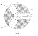
- the reactor A comprises the units 1, which are preferably 18 in number, being geometrically arranged three by three on a stage, situation in which each stage is rotated relatively to the previous stage by an angle of 72 degrees.
- the units 1 are arranged inside a thermally insulating support 3, preferably made up of wood, each being positioned in one of the holes 4.
- Each unit 1 has a metal core 6, whose surface is in direct contact with a vertical pipe 2 made up of a diamagnetic material, which confines a treatment chamber a.
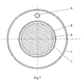
- An electromagnetic unit 1 comprises a metal core 6, an electric coil 8 used as a source of generating a magnetic field.
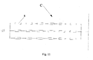
- the coils 8 of the units 1 are power supplied through a number of connecting ends 11, preferably arranged on three rows, connected in parallel, to six coils 8 serially connected within the wiring diagram of the electric panel C.
- Each unit 1 is equipped with a heat exchange tank 7 having the role of maintaining the unit 1 at a constant temperature ranging between 31°C and 65°C. By maintaining the unit 1 at the working temperature, there is greatly increased the probability of connection between the magnetic field produced by the metal core 6 placed inside the coil 8, and the magnetic momentum of spin of the zero pairs.
- the oil used as a thermal medium flows inside the tank 7, being introduced thereinto through a supply pipe 9, and wherefrom it is taken over by a discharge pipe 10.
- the pipes 9 and 10 have equal diameters, but the pipe 9 is longer than the discharge pipe 10, the ratio between their lengths being of 2 - 2,5, so as to have a swirling flow of oil inside the tank 7, fact that leads to a uniform heating or cooling of the electromagnetic unit 1.
- the oil takes over the heat in excess or brings a heat uptake in the case of a temperature lower than the working temperature, such operations being necessary for maintaining the unit 1 at the working temperature.
- the pipe 9 of a unit 1 is connected to the pipe 10 of the following electromagnetic unit 1, in the succession of the 18 units 1, thereby achieving the series connection of all 18 tanks 7, so that the oil pushed by the pump P could pass successively therethrough.
- the circuit B provides the heating of the oil through the heating resistors placed inside the tank R wherein the oil is stored. At the same time the cooling of the oil can also be carried out by its being passed through the oil radiator E.
- the pumping of the oil into the tanks 7 of the 18 units 1 is achieved by means of the pump P, which carry out both the oil supply of the electromagnetic units 1 and the transfer of the oil discharged therefrom.
- the oil transport circuit comprises some thermally insulated conduits which make the series connection of the tanks 7 in the 18 electromagnetic units 1 with the oil tank R by means of the pump P which carries out the oil flow in closed-circuit.
- the oil radiator E for cooling the oil is located within the oil transport circuit and is driven only when there is necessary to discharge the heat in excess, as a consequence of exceeding the working temperature.
- the electric panel C carries out the electric power supply by means of a rectifier 20 which supplies, electric power at a required voltage for generating the magnetic field to all the 18 units 1. Also, the electric panel C provides the power supply of the electric resistors inside the tank R, as well as the power supply needed for driving a ventilating unit that the cooler E is equipped with, in order to cool the oil and to drive the pump P. In order to maintain the 18 electromagnetic units 1 at an established working temperature, a thermocouple 17 for the oil and a thermocouple 18 for the units 1 are provided, together with a number of relays 16 for driving the pump P supplied with electric power from the electric panel C.
- a central unit 14 there are actuated the power supply and the disconnection of the relays 15 and 16, of the thermocouples 17, 18 and 19, and of the rectifier 20, in order to maintain the units 1 at the working temperature by correlating the values of the temperature parameters given by the thermocouple 17 for the oil and by the thermocouple 18 set in each electromagnetic unit 1.
- the central unit 14 also controls the power supply of the electric resistors in the tank R and the pump P when the temperature of the electromagnetic units 1 is lower than the temperature needed for the reactor A.
- the oil is heated in the tank R by means of the electric resistors, and circulated through the heat circuit by means of the pump P, thereby getting into the tanks 7 of the units 1, fact that leads to the heating of the metal core 6, which thus reaches the optimum temperature needed for the connection with the zero fluctuations of the vacuum for increasing the burning energy released upon the combustion of the gas treated in the reactor A.
- the central unit 14 also controls the cooling of the units 1 by ceasing the power supply of the electric resistors when the thermocouple 18 records a higher temperature than the temperature needed in the reactor A. By flowing the oil inside the cooler E and by starting-up the cooling ventilating unit, the oil is cooled, releasing the heat in excess taken over from the units 1 through the heat exchange tanks 7, outside the reactor A.
- the units 1 are cooled and their temperature is lowered up to reaching the working temperature of the reactor A, when the zero vacuum energy can be extracted for increasing the burning energy produced by the natural gas flowing through the reactor A.
- the heating and the cooling of the electromagnetic unit 1 is achieved in an optimum time interval when the heated or cooled oil, as the case may be, is introduced into each tank 7 through the pipe 9 and is discharged through the pipe 10, thereby achieving a swirling flow without high temperature gradients inside the electromagnetic unit 1.
- the decreasing values of the magnetic field can be ensured, in the flowing direction of the natural gas through the treatment chamber confined within the pipe 2 , in said situation, the value of the magnetic field being between 0,1 and 0,8 T, each electromagnetic unit being maintained at the same temperature ranging between 31° C and 65°C.
- each electromagnetic unit 1 has a value ranging between 0,030 ... 0,228 Wb, irrespective of the connections in series or in parallel of the electromagnetic units 1.
- the series or parallel connections of the electromagnetic units 1 should preferably be carried out in series in hot weather (in summer, respectively), and in parallel in cold weather (in winter, respectively).
- the coil 8 provides, by means of the core 6, a continuous magnetic field outside thereof.
- This field is necessary for the operation of the electromagnetic unit 1 in order to balance, in the area adjacent to the diamagnetic pipe 2, the magnetic momentum of the zero pairs occurring upon the vacuum fluctuation.
- the natural gas path consists of a conduit D for the inlet of the gas, said conduit crosses the oil tank R, which makes a pre-heating of the natural gas, the pipe 2 passes axially through the reactor A, crossing a hole 5 cut in the support 3 for the electromagnetic units 1.
- the pipe 2 carries out the natural gas exposure to the physical action of the rotating magnetic and thermal fields of the electromagnetic units 1, is in direct contact with the ends of the metal cores 6 and is connected to the conduit D for the inlet of the gas in order to be pre-heated, through a supply connection 12.
- a connection 13 for the outlet of the natural gas achieves the connection between the diamagnetic pipe 2 and the conduit D for the outlet of the natural gas towards some natural gas burners not shown in figures.
- the fluctuation of the spatial metrics modifies the eigen values of the energy levels for the layers of electrons within the atoms, the Srodinger equation having in this case a dynamic aspect.
- These changes within the energy spectrum of the electrons inside the atoms last for an extremely short period of time, according to the life time of the zero fluctuations of the vacuum, the possible energy in excess released within an exothermal chemical reaction being imperceptible.
- the electromagnetic units 1 produce a polarization of the zero vacuum pairs.
- the particle-antiparticle pairs occurring in vacuum according to the Heisenberg principle have magnetic momentum of spin.
- the electromagnetic units 1 cause the spin of these particle-antiparticle pairs to remain blocked in a spatial region coinciding with the diamagnetic pipe 2 wherethrough the natural gas passes.
- the heating of the electromagnetic units 1 to the working temperature leads to achieving a powerful connection between the magnetic field of the electromagnetic units 1 and the spin of the zero pairs which occur within the vacuum fluctuations.
- the metrics of the space is stabilized for a relatively long period of time, sufficient for the atoms comprised in the natural gas composition to modify their own levels of energy upon their passing through this zone.
- the natural gas molecule includes this energy in excess caused by the modification of the metrics inside the reactor A and carries the same onto the path inside the pipe 2, this energy in excess being released within the chemical reactions of combusting the natural gas.
- An increase of the gas burning energy takes place in the reactor A, by the action of the 18 electromagnetic units 1 which are maintained during their operation at a certain working temperature.
- the natural gas is introduced into the installation through the gas conduit at a pressure within 2,5 and 3,5 bar, the conduit crosses the tank R, thereby achieving a pre-heating of the tank to the working temperature of the reactor A, thereafter it undergoes an expansion within the diamagnetic pipe 2.
- the ratio between the diameter of the pipe 2 passing through the reactor A and the conduit D connected therewith for the natural gas supply ranges between 3 and 6.
- the natural gas slows down its transport speed inside the diamagnetic pipe 2, remaining for 1-2 seconds under the action of the 18 electromagnetic units 1 which determine the modification of the quantum energy levels of the molecules.
- the electromagnetic units 1 are brought to the working temperature through the action of the heated oil passing through the tanks 7 and carry out the energetic addition within the gas molecule by freezing the space metrics at a quantum level and extracting the zero vacuum energy. After the gas gets out of the diamagnetic pipe 2, it is handled towards the burners, where the caloric excess caused by the extraction of a part of the zero energy of the vacuum is pointed out. By increasing the caloric power, the new quantity of gas to be burnt is smaller than in the situation when the natural gas does not include a part of the zero energy of the vacuum that is extracted in the reactor A.
- the invention ensures an important economy of natural gas, leading to the substantial reduction of the energy expenses.
- the invention is liable of being standardized to the effect that it can be sized for any natural gas flow rate chosen for the technological heating processes.
- the installation for increasing the caloric power of the natural gas employs the electric power to operate, consequently it is not electromagnetically polluting, it does not release noxious substances into the environment, it is carried out by using usual materials, it is secure and easy to use and to maintain.
- the ratio between the electric power consumed for operating the reactor A and the supplementary energy extracted from the zero fluctuations of the vacuum is 1/24.
- the large-scale application of the installation can lead to lowering the heating expenses for the population during the winter, fact that, from a social viewpoint, can be a real advantage. Its application in industry can lead to sensitive reductions of the energy expenses for the energy-consuming production sectors and implicitly to the reduction in price of certain products destined to the market.
Landscapes
- Engineering & Computer Science (AREA)
- Chemical & Material Sciences (AREA)
- Combustion & Propulsion (AREA)
- Mechanical Engineering (AREA)
- General Engineering & Computer Science (AREA)
- Chemical Kinetics & Catalysis (AREA)
- Physical Or Chemical Processes And Apparatus (AREA)
- Feeding And Controlling Fuel (AREA)
- Fluidized-Bed Combustion And Resonant Combustion (AREA)
- Gas Burners (AREA)
- Waste-Gas Treatment And Other Accessory Devices For Furnaces (AREA)
- Liquid Carbonaceous Fuels (AREA)
Claims (6)
- Verfahren zur Erhöhung der von Erdgas erzeugten Verbrennungsenergie, gekennzeichnet durch die Schritte, dass das Erdgas einer Behandlungskammer zugeführt wird, die von einer aus diamagnetischem Material hergestellten, zylinderförmigen Wand begrenzet ist, außerhalb der spiralförmig eine Anzahl von elektromagnetischen Einheiten angeordnet ist, von welchen die am Ende gelegenen bezüglich der Längs-Vertikalachse der Kammer diametral gegenüberliegen, um ein rotierendes magnetisches Feld zu erzeugen, welches nur in einer Polarität auf das Gas wirkt, unter der Vorraussetzung, dass gleichzeitig ein rotierendes thermisches Feld, das von den auf einer Temperatur zwischen 31° C und 65° C gehaltenen Kernen der elektromagnetischen Einheiten erzeugt wird, auf das Gas einwirkt, wodurch ein Energietransfer von den Nullfluktuationen des Vakuums zur der Erdgasmasse, welche die Kammer in einem nach oben verlaufen Fluss durchsetzt, gewährleistet ist, und das Gas vor seinem Eintritt in die Kammer vorgewärmt wird und eine zwischen 18° C und 30° C liegende Temperatur beisitzt, und schließlich das so behandelte Gas in Richtung eines Brenners geleitet wird.
- Verfahren nach Anspruch 1, bei welchem die elektromagnetischen Einheiten mit Strom versorgt werden können, wobei sie in Parallelschaltung die gleiche feldstärke oder in Serienschaltung unterschiedliche Feldstärke aufweisen, wobei deren Wert in Flussrichtung des Erdgases durch die Behandlungskammer abnimmt, und dabei die Stärke des magnetischen Feldes zwischen 0,1 und 0,8 T liegt und jede elektromagnetische Einheit auf der gleichen Temperatur zwischen 31° C und 65° C gehalten wird.
- Verfahren nach Anspruch 1 und Anspruch 2, bei welchem der magnetische Fluss durch den Kern jeder elektromagnetischen Einheit gewährleistet ist und, unabhängig davon, ob die elektromagnetischen Einheiten in Serie oder parallel geschalten sind, einen Wert zwischen 0,03 und 0,228 Wb aufweist.
- Anlage zur Durchführung des Verfahrens nach den Ansprüchen 1 bis 3, angewendet zur Erhöhung der von dem Erdgas erzeugten Brennenergie auf Grund der gleichzeitigen Einwirkung eines Magnetfeldes und eines thermischen Feldes auf das Gas, dadurch gekennzeichnet, dass sie aufweist einen Reaktor (A), der mit einer Anzahl elektromagnetischer, um ein aus diamagnetischem Material hergestelltes Rohr (2) hierum angeordneter Einheiten (1) ausgestattet ist, wobei jede Einheit (1) einen Metallkern (6) besitzt, welcher innerhalb einer mit elektrischen Anschlussenden (11) versehenen elektrischen Spule (8) angeordnet ist, einen Wärmeaustauschbehälter (7), welcher die Aufhabe hat, die elektromagnetische Einheit (1) auf einer das Wärmefeld definierenden, konstanten Temperatur zu halten, wobei der Kern (6) in Kontakt mit dem diamagnetischen Rohr (2) steht, welches eine Kammer (a) bildet, durch welche das Erdgas zirkuliert, um durch die erzeugten Felder behandelt zu werden, und die Einheiten (1) in Spiralform und in Stufen angeordnet sind, von welchen jede vorzugsweise drei Einheilen (1) besitzt, wobei jede Einheit (1) einer Stufe bezüglich einer anderen korrespondierenden Einheit (1) innerhalb der vorgehenden Stufe um einen zwischen 70° bis 73° liegenden Winkel verdreht ist, sodass zwischen der ersten und der sechsten Stufe eine komplette 360° Drehung erreicht wird, und die Einheiten (1) dadurch positioniert sind, dass sie in eine Anzahl von Öffnungen (4) eines thermisch isolierenden Halters (3) eingeführt werden, sodass die Endelektromagnetischen Einheiten (1) am Ende bezüglich der Längs-Vertikalachse des diamagnetischen Rohres (2) diametral gegenüber angeordnet sind, wodurch sich ein rotierendes magnetisches Feld mit einer einzigen Polung und ein rotierendes thermisches Feld ergibt, welche beide auf das Gas einwirken, ebenso einen Wärmekreislauf (B), der einen Behälter (R) zur Aufnahme des Öls von den Wärmeaustauschbehältern (7) besitzt, wobei in diesem Behälter (R) einige elektrische Heizwiderstände angeordnet sind, und nach Hochlaufen der Anlage das Öl durch die Wärmeaustauschbehälter (7) zirkuliert und darauffolgend zum Kühlen des Öls durch einen Radiator (E) geführt wird, und das gekühlt Öl in diesem Behälter ( R) mittels einer Pumpe (P) in die Wärmeaustauschbehälter (7) geführt wird, welche in dem Aufbau der elektromagnetischen Einheiten (1) des Reaktors (A) enthalten sind, sowie einen elektrischen Schaltschrank (C) zur Versorgung der elektrischen Spulen (8) mit elektrischem Strom, und Leitungen (D) für den Einlass bzw. Auslass des Erdgases in die bzw, aus der Kammer (a), wobei die Einlassleitung (D) durch den Behälter (R) in dem das Öl erwärmt wird, verläuft.
- Anlage nach Anspruch 4, dadurch gekennzeichnet, dass das als Wärmeträger verwendete Öl über eine Zufuhrleitung (9) in den Wärmeaustauschbehälter (7) geführt wird und über eine Abfuhrleitung (10) von hier abgeführt wird, wobei die Leitungen (9) und (10) gleichen Durchmesser besitzen, die Länge der Zufuhrleitung (9) jedoch größer ist als die Länge der anderen Leitung (10), und das Verhältnis der Längen dieser Leitungen zwischen 2 und 2,5 liegt, und sodann durch die Zufuhrleitung (9) einer Einheit (1) und durch die Abfuhrleitung (10) der folgenden Einheit (1), wodurch erreicht wird, dass alle Wärmeaustauschbehälter (7) in Serie miteinander verbunden sind.
- Anlage nach Anspruch 4, dadurch gekennzeichnet, dass das Verhältnis des Durchmessers des den Reaktor (A) durchsetzenden Rohres (2) und der daran angeschlossenen Leitung (D) zum Zuführen des Erdgases einen Wert zwischen 3 und 6 aufweist.
Priority Applications (3)
| Application Number | Priority Date | Filing Date | Title |
|---|---|---|---|
| SI200630600T SI1902253T1 (sl) | 2005-05-26 | 2006-05-19 | Postopek in naprava za povečanje zgorevalne energije naravnega gorilnega plina |
| PL06757922T PL1902253T3 (pl) | 2005-05-26 | 2006-05-19 | Sposób i urządzenie do zwiększania energii spalania paliwowego gazu ziemnego |
| CY20101100338T CY1110003T1 (el) | 2005-05-26 | 2010-04-14 | Μεθοδος και εγκατασταση για αυξηση της ενεργειας καυσης που παραγεται απο ενα καυσιμο φυσικο αεριο |
Applications Claiming Priority (3)
| Application Number | Priority Date | Filing Date | Title |
|---|---|---|---|
| RO200500503 | 2005-05-26 | ||
| ROA200600191A RO121655B1 (ro) | 2005-05-26 | 2006-03-23 | Procedeu şi instalaţie pentru creşterea energiei de combustie produsă de un gaz natural combustibil |
| PCT/RO2006/000010 WO2006126905A2 (en) | 2005-05-26 | 2006-05-19 | Process and installation for increasing the burning energy produced by a natural fuel gas |
Publications (3)
| Publication Number | Publication Date |
|---|---|
| EP1902253A2 EP1902253A2 (de) | 2008-03-26 |
| EP1902253B1 true EP1902253B1 (de) | 2010-01-27 |
| EP1902253B9 EP1902253B9 (de) | 2010-10-27 |
Family
ID=37452471
Family Applications (1)
| Application Number | Title | Priority Date | Filing Date |
|---|---|---|---|
| EP06757922A Active EP1902253B9 (de) | 2005-05-26 | 2006-05-19 | Verfahren und vorrichtung zur erhöhung der von einem natürlichen brennstoffgas produzierten brennenergie |
Country Status (22)
| Country | Link |
|---|---|
| US (1) | US8202083B2 (de) |
| EP (1) | EP1902253B9 (de) |
| JP (1) | JP2008542676A (de) |
| CN (1) | CN101184956A (de) |
| AP (1) | AP1964A (de) |
| AT (1) | ATE456771T1 (de) |
| AU (1) | AU2006250096B2 (de) |
| CA (1) | CA2608586C (de) |
| CY (1) | CY1110003T1 (de) |
| DE (1) | DE602006012049D1 (de) |
| DK (1) | DK1902253T5 (de) |
| EA (1) | EA014335B1 (de) |
| ES (1) | ES2339700T3 (de) |
| HR (1) | HRP20100196T1 (de) |
| NO (1) | NO330052B1 (de) |
| PL (1) | PL1902253T3 (de) |
| PT (1) | PT1902253E (de) |
| RO (1) | RO121655B1 (de) |
| RS (1) | RS51256B (de) |
| SI (1) | SI1902253T1 (de) |
| UA (1) | UA84526C2 (de) |
| WO (1) | WO2006126905A2 (de) |
Families Citing this family (4)
| Publication number | Priority date | Publication date | Assignee | Title |
|---|---|---|---|---|
| US8714967B2 (en) * | 2010-02-19 | 2014-05-06 | Roy Lee Garrison | High velocity burner apparatus and method |
| RO127836B1 (ro) * | 2012-03-12 | 2013-12-30 | Aurel Enache | Instalaţie pentru tratarea unui combustibil în vederea creşterii puterii calorice |
| RU152297U1 (ru) | 2012-10-15 | 2015-05-20 | Сергей Петрович СИДОРЕНКО | Проточная магнитная ячейка и устройство для магнитной обработки текучих сред на её основе |
| US9943092B1 (en) * | 2014-12-22 | 2018-04-17 | Roy Lee Garrison | Liquid processing system and method |
Family Cites Families (16)
| Publication number | Priority date | Publication date | Assignee | Title |
|---|---|---|---|---|
| US3277631A (en) * | 1962-11-28 | 1966-10-11 | Soudure Electr Autogene | Process and apparatus for separation of a gas mixture |
| GB1048304A (en) * | 1964-04-28 | 1966-11-16 | Central Electr Generat Board | Improvements in or relating to magnetohydrodynamic electrical generator systems |
| US3439899A (en) * | 1967-02-27 | 1969-04-22 | Magneto Dynamics Inc | Method for the production and control of fluidized beds |
| US4136016A (en) * | 1975-09-03 | 1979-01-23 | Exxon Research & Engineering Co. | Hydrocarbon conversion process utilizing a magnetic field in a fluidized bed of catalitic particles |
| US4238183A (en) * | 1979-04-30 | 1980-12-09 | Robinson T Garrett | Method and device for increasing efficiency of natural gas fuel |
| US4254558A (en) * | 1979-07-31 | 1981-03-10 | Exxon Research & Engineering Co. | Louvered magnetically stabilized fluid cross-flow contactor and processes for using the same |
| US4254557A (en) * | 1979-07-31 | 1981-03-10 | Exxon Research And Engineering Co. | Magnetically stabilized fluid cross-flow contactor and process for using the same |
| JPS61211619A (ja) * | 1986-01-24 | 1986-09-19 | Himeji Denshi Kk | 液体の改質装置 |
| US4755288A (en) * | 1986-09-12 | 1988-07-05 | Mitchell John | Apparatus and system for magnetically treating fluids |
| US5637226A (en) * | 1995-08-18 | 1997-06-10 | Az Industries, Incorporated | Magnetic fluid treatment |
| WO1997039284A1 (en) * | 1996-04-17 | 1997-10-23 | Velke William H | Combustion method and device for fluid hydrocarbon fuels |
| US5882514A (en) * | 1996-08-22 | 1999-03-16 | Fletcher; Charles J. | Apparatus for magnetically treating fluids |
| GB2323215B (en) * | 1997-03-14 | 2000-06-07 | Paragon Energy Conservation Sy | Fluid treatment device |
| US6271509B1 (en) * | 1997-04-04 | 2001-08-07 | Robert C. Dalton | Artificial dielectric device for heating gases with electromagnetic energy |
| US6235202B1 (en) * | 1998-11-16 | 2001-05-22 | Archimedes Technology Group, Inc. | Tandem plasma mass filter |
| HU227097B1 (hu) | 2004-11-03 | 2010-07-28 | Tamas Szalai | Mágneses kezelõegység folyékony és légnemû anyagokhoz |
-
2006
- 2006-03-23 RO ROA200600191A patent/RO121655B1/ro unknown
- 2006-05-19 DK DK06757922.7T patent/DK1902253T5/da active
- 2006-05-19 WO PCT/RO2006/000010 patent/WO2006126905A2/en not_active Ceased
- 2006-05-19 AT AT06757922T patent/ATE456771T1/de active
- 2006-05-19 CN CNA2006800183453A patent/CN101184956A/zh active Pending
- 2006-05-19 RS RSP-2010/0170A patent/RS51256B/sr unknown
- 2006-05-19 PL PL06757922T patent/PL1902253T3/pl unknown
- 2006-05-19 HR HR20100196T patent/HRP20100196T1/hr unknown
- 2006-05-19 UA UAA200714079A patent/UA84526C2/ru unknown
- 2006-05-19 AU AU2006250096A patent/AU2006250096B2/en not_active Ceased
- 2006-05-19 SI SI200630600T patent/SI1902253T1/sl unknown
- 2006-05-19 PT PT06757922T patent/PT1902253E/pt unknown
- 2006-05-19 US US11/920,965 patent/US8202083B2/en not_active Expired - Fee Related
- 2006-05-19 EA EA200702681A patent/EA014335B1/ru not_active IP Right Cessation
- 2006-05-19 JP JP2008513397A patent/JP2008542676A/ja active Pending
- 2006-05-19 AP AP2007004288A patent/AP1964A/xx active
- 2006-05-19 ES ES06757922T patent/ES2339700T3/es active Active
- 2006-05-19 CA CA2608586A patent/CA2608586C/en not_active Expired - Fee Related
- 2006-05-19 EP EP06757922A patent/EP1902253B9/de active Active
- 2006-05-19 DE DE602006012049T patent/DE602006012049D1/de active Active
-
2007
- 2007-12-06 NO NO20076296A patent/NO330052B1/no not_active IP Right Cessation
-
2010
- 2010-04-14 CY CY20101100338T patent/CY1110003T1/el unknown
Also Published As
| Publication number | Publication date |
|---|---|
| SI1902253T1 (sl) | 2010-05-31 |
| PL1902253T3 (pl) | 2010-07-30 |
| RS51256B (sr) | 2010-12-31 |
| CN101184956A (zh) | 2008-05-21 |
| AU2006250096A1 (en) | 2006-11-30 |
| ES2339700T3 (es) | 2010-05-24 |
| CY1110003T1 (el) | 2015-01-14 |
| US8202083B2 (en) | 2012-06-19 |
| DK1902253T3 (da) | 2010-05-17 |
| ATE456771T1 (de) | 2010-02-15 |
| AP2007004288A0 (en) | 2007-12-31 |
| HRP20100196T1 (hr) | 2010-05-31 |
| NO330052B1 (no) | 2011-02-07 |
| ES2339700T9 (es) | 2011-03-01 |
| PT1902253E (pt) | 2010-04-22 |
| DK1902253T5 (da) | 2011-02-14 |
| WO2006126905B1 (en) | 2007-04-12 |
| EP1902253B9 (de) | 2010-10-27 |
| DE602006012049D1 (de) | 2010-03-18 |
| CA2608586C (en) | 2010-02-09 |
| WO2006126905A3 (en) | 2007-03-01 |
| RO121655B1 (ro) | 2008-01-30 |
| EP1902253A2 (de) | 2008-03-26 |
| NO20076296L (no) | 2008-02-25 |
| US20090325109A1 (en) | 2009-12-31 |
| CA2608586A1 (en) | 2006-11-30 |
| EA014335B1 (ru) | 2010-10-29 |
| WO2006126905A2 (en) | 2006-11-30 |
| EA200702681A1 (ru) | 2008-08-29 |
| AP1964A (en) | 2009-03-03 |
| JP2008542676A (ja) | 2008-11-27 |
| UA84526C2 (ru) | 2008-10-27 |
| AU2006250096B2 (en) | 2010-04-15 |
Similar Documents
| Publication | Publication Date | Title |
|---|---|---|
| JP5372927B2 (ja) | 水を単体ガスに使用箇所で安価かつカーボンフリーに解離して水素関連発電を行う方法と装置 | |
| US10317070B2 (en) | Integrated combustion device power saving system | |
| NZ207176A (en) | Plasma generator:control of arc root position | |
| EP1902253B9 (de) | Verfahren und vorrichtung zur erhöhung der von einem natürlichen brennstoffgas produzierten brennenergie | |
| US20080044781A1 (en) | Method of solid fuel combustion intensification | |
| CN101413398A (zh) | 矿井乏风瓦斯氧化装置的加热启动系统 | |
| CN109952661A (zh) | 具有集成热电发电器的干式低NOx燃烧器 | |
| CN206204355U (zh) | 一种辐射加热装置 | |
| HK1114160A (en) | Process and installation for increasing the burning energy produced by a natural fuel gas | |
| EP3710767A1 (de) | Hochtemperaturofen | |
| RU2139236C1 (ru) | Установка для производства водорода, сажи и алмазов | |
| KR200393116Y1 (ko) | 자력화장치를 구비한 에너지 절감용 보일러 | |
| CN104848244B (zh) | 一种水解离混合气体燃料装置和方法 | |
| US12523373B1 (en) | Method and apparatus for thermal remediation of contaminant impacted media with hybrid energy systems | |
| US5100630A (en) | Water powered magneto generator for the production of nitrogen and phosphorus fertilizer apparatus | |
| CZ2021545A3 (cs) | Způsob rozkladu vody na plynný vodík a kyslík a zařízení k provedení tohoto způsobu | |
| JPH07332876A (ja) | 雰囲気炉 | |
| JP2011069600A (ja) | 電子活性機能水を利用する燃焼方法及びその装置 | |
| EP2798280A1 (de) | Verfahren zum erwärmen von flüssigkeiten und vorrichtung zu seiner durchführung | |
| RO125778A0 (ro) | Instalaţie şi procedeu pentru creşterea energiei de combustie produsă de un gaz natural combustibil | |
| CZ2007542A3 (cs) | Intenzifikacní zpusob spalování tuhých paliv | |
| JPS63254350A (ja) | ガス空間加熱ユニツト及び住居その他を加熱する方法 | |
| JP2002081639A (ja) | ボイラー燃焼効率増幅装置 |
Legal Events
| Date | Code | Title | Description |
|---|---|---|---|
| PUAI | Public reference made under article 153(3) epc to a published international application that has entered the european phase |
Free format text: ORIGINAL CODE: 0009012 |
|
| 17P | Request for examination filed |
Effective date: 20071214 |
|
| AK | Designated contracting states |
Kind code of ref document: A2 Designated state(s): AT BE BG CH CY CZ DE DK EE ES FI FR GB GR HU IE IS IT LI LT LU LV MC NL PL PT RO SE SI SK TR |
|
| AX | Request for extension of the european patent |
Extension state: AL BA HR MK YU |
|
| EL | Fr: translation of claims filed | ||
| GRAP | Despatch of communication of intention to grant a patent |
Free format text: ORIGINAL CODE: EPIDOSNIGR1 |
|
| GRAJ | Information related to disapproval of communication of intention to grant by the applicant or resumption of examination proceedings by the epo deleted |
Free format text: ORIGINAL CODE: EPIDOSDIGR1 |
|
| GRAP | Despatch of communication of intention to grant a patent |
Free format text: ORIGINAL CODE: EPIDOSNIGR1 |
|
| GRAS | Grant fee paid |
Free format text: ORIGINAL CODE: EPIDOSNIGR3 |
|
| GRAA | (expected) grant |
Free format text: ORIGINAL CODE: 0009210 |
|
| AK | Designated contracting states |
Kind code of ref document: B1 Designated state(s): AT BE BG CH CY CZ DE DK EE ES FI FR GB GR HU IE IS IT LI LT LU LV MC NL PL PT RO SE SI SK TR |
|
| AX | Request for extension of the european patent |
Extension state: AL BA HR MK YU |
|
| REG | Reference to a national code |
Ref country code: GB Ref legal event code: FG4D |
|
| REG | Reference to a national code |
Ref country code: CH Ref legal event code: EP |
|
| REG | Reference to a national code |
Ref country code: IE Ref legal event code: FG4D |
|
| REF | Corresponds to: |
Ref document number: 602006012049 Country of ref document: DE Date of ref document: 20100318 Kind code of ref document: P |
|
| REG | Reference to a national code |
Ref country code: HR Ref legal event code: TUEP Ref document number: P20100196 Country of ref document: HR |
|
| REG | Reference to a national code |
Ref country code: CH Ref legal event code: NV Representative=s name: E. BLUM & CO. AG PATENT- UND MARKENANWAELTE VSP |
|
| REG | Reference to a national code |
Ref country code: GR Ref legal event code: EP Ref document number: 20100400777 Country of ref document: GR Ref country code: NL Ref legal event code: T3 |
|
| REG | Reference to a national code |
Ref country code: PT Ref legal event code: SC4A Free format text: AVAILABILITY OF NATIONAL TRANSLATION Effective date: 20100415 |
|
| REG | Reference to a national code |
Ref country code: RO Ref legal event code: EPE |
|
| REG | Reference to a national code |
Ref country code: SE Ref legal event code: TRGR |
|
| REG | Reference to a national code |
Ref country code: DK Ref legal event code: T3 |
|
| REG | Reference to a national code |
Ref country code: ES Ref legal event code: FG2A Ref document number: 2339700 Country of ref document: ES Kind code of ref document: T3 |
|
| REG | Reference to a national code |
Ref country code: HR Ref legal event code: T1PR Ref document number: P20100196 Country of ref document: HR |
|
| REG | Reference to a national code |
Ref country code: SK Ref legal event code: T3 Ref document number: E 7086 Country of ref document: SK |
|
| REG | Reference to a national code |
Ref country code: PL Ref legal event code: T3 |
|
| PG25 | Lapsed in a contracting state [announced via postgrant information from national office to epo] |
Ref country code: PL Free format text: LAPSE BECAUSE OF FAILURE TO SUBMIT A TRANSLATION OF THE DESCRIPTION OR TO PAY THE FEE WITHIN THE PRESCRIBED TIME-LIMIT Effective date: 20100127 |
|
| REG | Reference to a national code |
Ref country code: HU Ref legal event code: AG4A Ref document number: E008062 Country of ref document: HU |
|
| PLBE | No opposition filed within time limit |
Free format text: ORIGINAL CODE: 0009261 |
|
| STAA | Information on the status of an ep patent application or granted ep patent |
Free format text: STATUS: NO OPPOSITION FILED WITHIN TIME LIMIT |
|
| PGFP | Annual fee paid to national office [announced via postgrant information from national office to epo] |
Ref country code: CY Payment date: 20100510 Year of fee payment: 5 |
|
| 26N | No opposition filed |
Effective date: 20101028 |
|
| REG | Reference to a national code |
Ref country code: DK Ref legal event code: T5 |
|
| REG | Reference to a national code |
Ref country code: EE Ref legal event code: LD4A Ref document number: E004252 Country of ref document: EE |
|
| PG25 | Lapsed in a contracting state [announced via postgrant information from national office to epo] |
Ref country code: IT Free format text: LAPSE BECAUSE OF NON-PAYMENT OF DUE FEES Effective date: 20100519 |
|
| REG | Reference to a national code |
Ref country code: HR Ref legal event code: ODRP Ref document number: P20100196 Country of ref document: HR Payment date: 20110518 Year of fee payment: 6 |
|
| PGFP | Annual fee paid to national office [announced via postgrant information from national office to epo] |
Ref country code: CH Payment date: 20110525 Year of fee payment: 6 Ref country code: CZ Payment date: 20110420 Year of fee payment: 6 Ref country code: FR Payment date: 20110517 Year of fee payment: 6 Ref country code: ES Payment date: 20110520 Year of fee payment: 6 Ref country code: SE Payment date: 20110502 Year of fee payment: 6 Ref country code: PT Payment date: 20110502 Year of fee payment: 6 Ref country code: LV Payment date: 20110505 Year of fee payment: 6 Ref country code: MC Payment date: 20110502 Year of fee payment: 6 Ref country code: LU Payment date: 20110504 Year of fee payment: 6 Ref country code: LT Payment date: 20110506 Year of fee payment: 6 Ref country code: IS Payment date: 20110502 Year of fee payment: 6 Ref country code: IE Payment date: 20110429 Year of fee payment: 6 Ref country code: GR Payment date: 20110531 Year of fee payment: 6 Ref country code: TR Payment date: 20110516 Year of fee payment: 6 |
|
| PGRI | Patent reinstated in contracting state [announced from national office to epo] |
Ref country code: IT Effective date: 20110616 |
|
| PGFP | Annual fee paid to national office [announced via postgrant information from national office to epo] |
Ref country code: PL Payment date: 20110504 Year of fee payment: 6 Ref country code: SI Payment date: 20110503 Year of fee payment: 6 Ref country code: SK Payment date: 20110512 Year of fee payment: 6 Ref country code: NL Payment date: 20110516 Year of fee payment: 6 Ref country code: HU Payment date: 20110505 Year of fee payment: 6 Ref country code: GB Payment date: 20110526 Year of fee payment: 6 Ref country code: FI Payment date: 20110502 Year of fee payment: 6 Ref country code: AT Payment date: 20110502 Year of fee payment: 6 Ref country code: BE Payment date: 20110502 Year of fee payment: 6 Ref country code: BG Payment date: 20110527 Year of fee payment: 6 Ref country code: DK Payment date: 20110503 Year of fee payment: 6 Ref country code: EE Payment date: 20110531 Year of fee payment: 6 |
|
| PGFP | Annual fee paid to national office [announced via postgrant information from national office to epo] |
Ref country code: DE Payment date: 20110502 Year of fee payment: 6 Ref country code: IT Payment date: 20110512 Year of fee payment: 6 |
|
| PG25 | Lapsed in a contracting state [announced via postgrant information from national office to epo] |
Ref country code: CY Free format text: LAPSE BECAUSE OF NON-PAYMENT OF DUE FEES Effective date: 20110519 |
|
| REG | Reference to a national code |
Ref country code: HR Ref legal event code: PBON Ref document number: P20100196 Country of ref document: HR Effective date: 20120520 |
|
| REG | Reference to a national code |
Ref country code: PT Ref legal event code: MM4A Free format text: LAPSE DUE TO NON-PAYMENT OF FEES Effective date: 20121119 |
|
| BERE | Be: lapsed |
Owner name: ENACHE, AUREL Effective date: 20120531 Owner name: LUCA, LIVIU Effective date: 20120531 |
|
| REG | Reference to a national code |
Ref country code: NL Ref legal event code: V1 Effective date: 20121201 |
|
| REG | Reference to a national code |
Ref country code: LT Ref legal event code: MM4D Effective date: 20120519 |
|
| PG25 | Lapsed in a contracting state [announced via postgrant information from national office to epo] |
Ref country code: MC Free format text: LAPSE BECAUSE OF NON-PAYMENT OF DUE FEES Effective date: 20120531 |
|
| REG | Reference to a national code |
Ref country code: CH Ref legal event code: PL |
|
| REG | Reference to a national code |
Ref country code: SE Ref legal event code: EUG |
|
| REG | Reference to a national code |
Ref country code: AT Ref legal event code: MM01 Ref document number: 456771 Country of ref document: AT Kind code of ref document: T Effective date: 20120519 |
|
| REG | Reference to a national code |
Ref country code: DK Ref legal event code: EBP |
|
| GBPC | Gb: european patent ceased through non-payment of renewal fee |
Effective date: 20120519 |
|
| PG25 | Lapsed in a contracting state [announced via postgrant information from national office to epo] |
Ref country code: EE Free format text: LAPSE BECAUSE OF NON-PAYMENT OF DUE FEES Effective date: 20120531 Ref country code: SK Free format text: LAPSE BECAUSE OF NON-PAYMENT OF DUE FEES Effective date: 20120519 Ref country code: LI Free format text: LAPSE BECAUSE OF NON-PAYMENT OF DUE FEES Effective date: 20120531 Ref country code: FI Free format text: LAPSE BECAUSE OF NON-PAYMENT OF DUE FEES Effective date: 20120519 Ref country code: LT Free format text: LAPSE BECAUSE OF NON-PAYMENT OF DUE FEES Effective date: 20120519 Ref country code: HU Free format text: LAPSE BECAUSE OF NON-PAYMENT OF DUE FEES Effective date: 20120520 Ref country code: CH Free format text: LAPSE BECAUSE OF NON-PAYMENT OF DUE FEES Effective date: 20120531 Ref country code: IS Free format text: LAPSE BECAUSE OF FAILURE TO SUBMIT A TRANSLATION OF THE DESCRIPTION OR TO PAY THE FEE WITHIN THE PRESCRIBED TIME-LIMIT Effective date: 20121201 Ref country code: CZ Free format text: LAPSE BECAUSE OF NON-PAYMENT OF DUE FEES Effective date: 20120519 Ref country code: AT Free format text: LAPSE BECAUSE OF NON-PAYMENT OF DUE FEES Effective date: 20120519 |
|
| REG | Reference to a national code |
Ref country code: SK Ref legal event code: MM4A Ref document number: E 7086 Country of ref document: SK Effective date: 20120519 |
|
| REG | Reference to a national code |
Ref country code: GR Ref legal event code: ML Ref document number: 20100400777 Country of ref document: GR Effective date: 20121204 |
|
| REG | Reference to a national code |
Ref country code: EE Ref legal event code: MM4A Ref document number: E004252 Country of ref document: EE Effective date: 20120531 |
|
| REG | Reference to a national code |
Ref country code: IE Ref legal event code: MM4A |
|
| PG25 | Lapsed in a contracting state [announced via postgrant information from national office to epo] |
Ref country code: GR Free format text: LAPSE BECAUSE OF NON-PAYMENT OF DUE FEES Effective date: 20121204 Ref country code: PT Free format text: LAPSE BECAUSE OF NON-PAYMENT OF DUE FEES Effective date: 20121119 Ref country code: BE Free format text: LAPSE BECAUSE OF NON-PAYMENT OF DUE FEES Effective date: 20120531 Ref country code: IT Free format text: LAPSE BECAUSE OF NON-PAYMENT OF DUE FEES Effective date: 20120519 Ref country code: SE Free format text: LAPSE BECAUSE OF NON-PAYMENT OF DUE FEES Effective date: 20120520 Ref country code: LV Free format text: LAPSE BECAUSE OF NON-PAYMENT OF DUE FEES Effective date: 20120519 |
|
| REG | Reference to a national code |
Ref country code: SI Ref legal event code: KO00 Effective date: 20130128 |
|
| REG | Reference to a national code |
Ref country code: FR Ref legal event code: ST Effective date: 20130131 |
|
| REG | Reference to a national code |
Ref country code: DE Ref legal event code: R119 Ref document number: 602006012049 Country of ref document: DE Effective date: 20121201 |
|
| PG25 | Lapsed in a contracting state [announced via postgrant information from national office to epo] |
Ref country code: NL Free format text: LAPSE BECAUSE OF NON-PAYMENT OF DUE FEES Effective date: 20121201 |
|
| PG25 | Lapsed in a contracting state [announced via postgrant information from national office to epo] |
Ref country code: DK Free format text: LAPSE BECAUSE OF NON-PAYMENT OF DUE FEES Effective date: 20120531 Ref country code: IE Free format text: LAPSE BECAUSE OF NON-PAYMENT OF DUE FEES Effective date: 20120519 Ref country code: FR Free format text: LAPSE BECAUSE OF NON-PAYMENT OF DUE FEES Effective date: 20120531 Ref country code: GB Free format text: LAPSE BECAUSE OF NON-PAYMENT OF DUE FEES Effective date: 20120519 |
|
| PG25 | Lapsed in a contracting state [announced via postgrant information from national office to epo] |
Ref country code: SI Free format text: LAPSE BECAUSE OF NON-PAYMENT OF DUE FEES Effective date: 20120520 |
|
| PG25 | Lapsed in a contracting state [announced via postgrant information from national office to epo] |
Ref country code: DE Free format text: LAPSE BECAUSE OF NON-PAYMENT OF DUE FEES Effective date: 20121201 |
|
| PG25 | Lapsed in a contracting state [announced via postgrant information from national office to epo] |
Ref country code: BG Free format text: LAPSE BECAUSE OF NON-PAYMENT OF DUE FEES Effective date: 20121231 |
|
| PG25 | Lapsed in a contracting state [announced via postgrant information from national office to epo] |
Ref country code: PL Free format text: LAPSE BECAUSE OF NON-PAYMENT OF DUE FEES Effective date: 20120519 |
|
| REG | Reference to a national code |
Ref country code: PL Ref legal event code: LAPE |
|
| PG25 | Lapsed in a contracting state [announced via postgrant information from national office to epo] |
Ref country code: ES Free format text: LAPSE BECAUSE OF NON-PAYMENT OF DUE FEES Effective date: 20120520 |
|
| PGFP | Annual fee paid to national office [announced via postgrant information from national office to epo] |
Ref country code: RO Payment date: 20120323 Year of fee payment: 7 |
|
| REG | Reference to a national code |
Ref country code: ES Ref legal event code: FD2A Effective date: 20131031 |
|
| PG25 | Lapsed in a contracting state [announced via postgrant information from national office to epo] |
Ref country code: TR Free format text: LAPSE BECAUSE OF NON-PAYMENT OF DUE FEES Effective date: 20120519 Ref country code: RO Free format text: LAPSE BECAUSE OF NON-PAYMENT OF DUE FEES Effective date: 20130519 |
|
| PG25 | Lapsed in a contracting state [announced via postgrant information from national office to epo] |
Ref country code: LU Free format text: LAPSE BECAUSE OF NON-PAYMENT OF DUE FEES Effective date: 20120519 |