EP1901579A2 - Microphone module and mounting structure adapted to portable electronic device - Google Patents
Microphone module and mounting structure adapted to portable electronic device Download PDFInfo
- Publication number
- EP1901579A2 EP1901579A2 EP07017239A EP07017239A EP1901579A2 EP 1901579 A2 EP1901579 A2 EP 1901579A2 EP 07017239 A EP07017239 A EP 07017239A EP 07017239 A EP07017239 A EP 07017239A EP 1901579 A2 EP1901579 A2 EP 1901579A2
- Authority
- EP
- European Patent Office
- Prior art keywords
- housing
- microphone module
- circuit board
- mount portion
- extended portions
- Prior art date
- Legal status (The legal status is an assumption and is not a legal conclusion. Google has not performed a legal analysis and makes no representation as to the accuracy of the status listed.)
- Withdrawn
Links
Images


Classifications
-
- H—ELECTRICITY
- H04—ELECTRIC COMMUNICATION TECHNIQUE
- H04R—LOUDSPEAKERS, MICROPHONES, GRAMOPHONE PICK-UPS OR LIKE ACOUSTIC ELECTROMECHANICAL TRANSDUCERS; ELECTRIC HEARING AIDS; PUBLIC ADDRESS SYSTEMS
- H04R1/00—Details of transducers, loudspeakers or microphones
- H04R1/08—Mouthpieces; Microphones; Attachments therefor
-
- H—ELECTRICITY
- H04—ELECTRIC COMMUNICATION TECHNIQUE
- H04M—TELEPHONIC COMMUNICATION
- H04M1/00—Substation equipment, e.g. for use by subscribers
- H04M1/02—Constructional features of telephone sets
- H04M1/03—Constructional features of telephone transmitters or receivers, e.g. telephone hand-sets
-
- H—ELECTRICITY
- H04—ELECTRIC COMMUNICATION TECHNIQUE
- H04R—LOUDSPEAKERS, MICROPHONES, GRAMOPHONE PICK-UPS OR LIKE ACOUSTIC ELECTROMECHANICAL TRANSDUCERS; ELECTRIC HEARING AIDS; PUBLIC ADDRESS SYSTEMS
- H04R1/00—Details of transducers, loudspeakers or microphones
- H04R1/02—Casings; Cabinets ; Supports therefor; Mountings therein
-
- H—ELECTRICITY
- H04—ELECTRIC COMMUNICATION TECHNIQUE
- H04R—LOUDSPEAKERS, MICROPHONES, GRAMOPHONE PICK-UPS OR LIKE ACOUSTIC ELECTROMECHANICAL TRANSDUCERS; ELECTRIC HEARING AIDS; PUBLIC ADDRESS SYSTEMS
- H04R1/00—Details of transducers, loudspeakers or microphones
- H04R1/06—Arranging circuit leads; Relieving strain on circuit leads
-
- H—ELECTRICITY
- H05—ELECTRIC TECHNIQUES NOT OTHERWISE PROVIDED FOR
- H05K—PRINTED CIRCUITS; CASINGS OR CONSTRUCTIONAL DETAILS OF ELECTRIC APPARATUS; MANUFACTURE OF ASSEMBLAGES OF ELECTRICAL COMPONENTS
- H05K1/00—Printed circuits
- H05K1/02—Details
- H05K1/14—Structural association of two or more printed circuits
- H05K1/141—One or more single auxiliary printed circuits mounted on a main printed circuit, e.g. modules, adapters
-
- H—ELECTRICITY
- H04—ELECTRIC COMMUNICATION TECHNIQUE
- H04R—LOUDSPEAKERS, MICROPHONES, GRAMOPHONE PICK-UPS OR LIKE ACOUSTIC ELECTROMECHANICAL TRANSDUCERS; ELECTRIC HEARING AIDS; PUBLIC ADDRESS SYSTEMS
- H04R2499/00—Aspects covered by H04R or H04S not otherwise provided for in their subgroups
- H04R2499/10—General applications
- H04R2499/11—Transducers incorporated or for use in hand-held devices, e.g. mobile phones, PDA's, camera's
-
- H—ELECTRICITY
- H05—ELECTRIC TECHNIQUES NOT OTHERWISE PROVIDED FOR
- H05K—PRINTED CIRCUITS; CASINGS OR CONSTRUCTIONAL DETAILS OF ELECTRIC APPARATUS; MANUFACTURE OF ASSEMBLAGES OF ELECTRICAL COMPONENTS
- H05K1/00—Printed circuits
- H05K1/02—Details
- H05K1/0284—Details of three-dimensional rigid printed circuit boards
-
- H—ELECTRICITY
- H05—ELECTRIC TECHNIQUES NOT OTHERWISE PROVIDED FOR
- H05K—PRINTED CIRCUITS; CASINGS OR CONSTRUCTIONAL DETAILS OF ELECTRIC APPARATUS; MANUFACTURE OF ASSEMBLAGES OF ELECTRICAL COMPONENTS
- H05K2201/00—Indexing scheme relating to printed circuits covered by H05K1/00
- H05K2201/04—Assemblies of printed circuits
- H05K2201/049—PCB for one component, e.g. for mounting onto mother PCB
-
- H—ELECTRICITY
- H05—ELECTRIC TECHNIQUES NOT OTHERWISE PROVIDED FOR
- H05K—PRINTED CIRCUITS; CASINGS OR CONSTRUCTIONAL DETAILS OF ELECTRIC APPARATUS; MANUFACTURE OF ASSEMBLAGES OF ELECTRICAL COMPONENTS
- H05K2201/00—Indexing scheme relating to printed circuits covered by H05K1/00
- H05K2201/09—Shape and layout
- H05K2201/09009—Substrate related
- H05K2201/09072—Hole or recess under component or special relationship between hole and component
-
- H—ELECTRICITY
- H05—ELECTRIC TECHNIQUES NOT OTHERWISE PROVIDED FOR
- H05K—PRINTED CIRCUITS; CASINGS OR CONSTRUCTIONAL DETAILS OF ELECTRIC APPARATUS; MANUFACTURE OF ASSEMBLAGES OF ELECTRICAL COMPONENTS
- H05K2201/00—Indexing scheme relating to printed circuits covered by H05K1/00
- H05K2201/10—Details of components or other objects attached to or integrated in a printed circuit board
- H05K2201/10007—Types of components
- H05K2201/10083—Electromechanical or electro-acoustic component, e.g. microphone
Definitions
- a housing 85 including the cavity S2 and the sound hole 83 is formed using the resin mold 73 and the cover board 75.
- Extended portions 87 which are extended from the housing 85 in a horizontal direction perpendicular to the opening direction C of the sound hole 83, are formed using the extended portions of the leads 77, which are extended from the resin mold 73.
- the leads 77 serve as external connection terminals that are electrically connected to the microphone chip 15.
- the surface 117a of the housing 117 of the microphone module 101 is lower than the opposite surface 45 of the circuit board 7; but this is not a restriction. That is, the surface 117a of the housing 117 can be placed substantially in the same plane with the opposite surface 45 of the circuit board 7; alternatively, it can be placed higher than the opposite surface 45 of the circuit board 7.
- the microphone module 101 which is installed in the portable electronic device 102 by way of the aforementioned mounting structure, is arranged in such a way that the housing 117, which vertically projects above the surfaces 123a of the extended portions 123, is inserted into and engaged with the through-hole 47 of the circuit board 7, wherein it is possible to reduce the projection height of the microphone module 101, which vertically projects from the mount portion 9 of the circuit board 7.
- FIG. 10 shows a potable electronic device 155 incorporating a microphone module 145, which is mounted on a circuit board 147 in such a way that the surface 117a of the housing 117 is directed to a mount portion 149 of the circuit board 147.
- it is necessary to form a through-hole 151 which allows a sound hole 115 to communicate with the exterior, in the circuit board 147. Due to the aforementioned constitution of the microphone module 145 mounted on the circuit board 147, even when an opposite surface 153 of the circuit board 147 is positioned opposite to the sound port 6a of the housing 6, the sound hole 115 can directly face the sound port 6a via the through-hole 151 of the circuit board 147.
- an anti-sound-leak gasket 157 be arranged between the sound port 6a of the housing 6 and the through-hole 151 of the circuit board 147, which are positioned opposite to each other.
Landscapes
- Engineering & Computer Science (AREA)
- Signal Processing (AREA)
- Physics & Mathematics (AREA)
- Acoustics & Sound (AREA)
- Microelectronics & Electronic Packaging (AREA)
- Details Of Audible-Bandwidth Transducers (AREA)
- Telephone Set Structure (AREA)
- Transmitters (AREA)
- Electrostatic, Electromagnetic, Magneto- Strictive, And Variable-Resistance Transducers (AREA)
Abstract
Description
- The present invention relates to microphone modules for receiving and detecting sounds. The present invention also relates to mounting structures for installing microphone modules in portable electronic devices.
- This application claims priority on
Japanese Patent Application No. 2006-244268 - Conventionally-known portable electronic devices such as portable telephones and cellular phones are equipped with microphone modules for receiving and detecting sounds. For example,
U.S. Patent Application Publication No. 2006/0116180 teaches an acoustic transducer module, i.e., a miniature silicon condenser microphone module adapted to micro-electromechanical systems (MEMS). This type of the microphone module includes an external connection terminal and a sound hole to enter sound, both of which are formed on the exterior surface of a housing having a hollow cavity. This microphone module is mounted on a mount portion of a circuit board included in the housing of a portable electronic device. The external connection terminal of the microphone module is brought into contact with a connection pad formed on the mount portion, thus establishing an electrical connection between the circuit board and the microphone module. - When the conventionally-known microphone module is installed in the portable electronic device, it is necessary to precisely mount the microphone module on the mount portion of the circuit board in such a way that a sound port of the housing of the portable electronic device, which allows the entry of sound, is positioned opposite to the sound hole of the housing of the microphone module. For this reason, it is necessary to appropriately change the positions of the external connection terminal and sound hole formed on the exterior surface of the housing of the microphone module in consideration of the position of the mount portion of the circuit board in relation to the sound port of the housing of the portable electronic device.
- When the mount portion of the circuit board is positioned opposite to the sound port of the portable electronic device, it is necessary to form the sound hole and the external connection terminal on the opposite surfaces positioned opposite to each other within the exterior of the housing of the microphone module.
- When the prescribed surface of the circuit board opposite to its mount portion is positioned opposite to the sound port of the portable electronic device, it is necessary to form both the sound hole and the external connection terminal on the same surface within the exterior of the housing of the microphone module. In this case, it is necessary to form a through-hole running through the circuit board in its thickness direction, via which the sound hole of the microphone module directly faces the sound port of the portable electronic device.
- As described above, the conventionally-known microphone module is troublesome because it is necessary to change the positions of the external connection terminal and sound hole within the exterior in response to the position of the mount portion of the circuit board, which is positioned relative to the sound port of the portable electronic device. This reduces the degree of freedom in mounting the microphone module on the mount portion of the circuit board.
- Since the conventionally-known microphone module is designed to suit the mount portion of the circuit board, the height of the microphone module substantially matches the projection height realized by the microphone module projecting from the mount portion of the circuit board. This causes a limitation for reducing the size of the housing in which the microphone module is mounted on the circuit board.
- It is an object of the present invention to provide a microphone module and its mounting structure, by which the degree of freedom is increased with respect to the mounting operation of the microphone module installed in the portable electronic device.
- It is another object of the present invention to provide a portable electronic device having a reduced thickness, which realizes stable installation of the microphone module by use of the mounting structure.
- In a first aspect of the present invention, a microphone module includes a housing having a hollow cavity and a sound hole, via which the hollow cavity communicates with the exterior, a microphone chip for detecting sound inside of the hollow cavity, a plurality of external connection terminals that are electrically connected to the microphone chip, and a plurality of extended portions that are horizontally extended from both ends of the housing in the direction perpendicular to the opening direction of the sound hole, wherein the external connection terminals are each elongated onto one of surfaces and backsides of the extended portions, and wherein the housing partially projects from the surfaces of the extended portions.
- The housing of the microphone module is inserted into a recess or through-hole of the circuit board and is then mounted on the mount portion of the circuit board, wherein the depth of the recess is larger than the projection height of the housing that projects from the surfaces of the extended portions. Herein, the housing is inserted into the through-hole in such a way that the surfaces of the extended portions come in contact with the mount portion of the circuit board in the periphery of the through-hole, whereby the external connection terminals formed on the surfaces of the extended portions are brought into contact with connection pads that are formed in the periphery of the through-hole on the mount portion of the circuit board, thus reliably establishing an electrical connection between the microphone module and the circuit board. ,
- Since the housing is partially held inside the through-hole of the circuit board, it is possible to reduce the projection height of the microphone module; it is possible to avoid the positional deviation of the microphone module relative to the circuit board; and it is possible to improve the mounting strength (or packaging strength) of the microphone module mounted on the circuit board.
- In the above, the external connection terminals are each elongated onto the backside of the housing, which is positioned opposite to the surfaces of the extended portions. Since the external connection terminals are exposed on both of the surfaces and backsides of the extended portions, it is possible to reliably mount the microphone module without changing the positions of the external connection terminals in such a way that the surfaces of the extended portions are positioned opposite to the mount portion of the circuit board, alternatively, in such a way that the backsides of the extended portions are positioned opposite to the mount portion of the circuit board. In addition, even when the sound hole is opened in either the surface or backside of the housing, it is possible to reliably mount the microphone module on the circuit board in such a way that the sound hole is opened above the mount portion, or the sound hole is opened above the opposite surface of the circuit board opposite to the mount portion.
- When the sound hole is formed at a height above the surfaces of the extended portions of the housing, a ring-shaped anti-sound-leak gasket is attached to the microphone module before the microphone module is mounted on the circuit board in such a way that the backsides of the extended portions are positioned opposite to the mount portion of the circuit board. That is, when the housing, which partially projects from the surfaces of the extended portions, is engaged inside of the ring-shaped anti-sound-leak gasket, the terminal portion of the anti-sound-leak gasket comes in contact with the surfaces of the extended portions; hence, it is possible to easily establish positioning of the anti-sound-leak gasket relative to the microphone module. This eliminates the necessity of attaching the anti-sound-leak gasket to the microphone module after the microphone module is mounted on the circuit board; hence, it is possible to reliably maintain an electrical connection between the microphone module and the circuit board.
- In addition, the housing is constituted of a substrate for fixedly mounting the microphone chip on the surface thereof and a cover member that covers the surface of the substrate so as to form the hollow cavity, wherein the extended portions are formed using the substrate and are extended externally from the cover member. Furthermore, the extended portions are formed using a plurality of leads, each having a conductivity, which serve as the external connection terminals, wherein the housing is formed using a resin mold for sealing the leads.
- Alternatively, the microphone module is basically constituted of a main body and a support for mounting and supporting the main body. The main body is constituted of a housing having a hollow cavity, a microphone chip that is arranged inside of the hollow cavity so as to detect sound, and a plurality of external connection terminals that are each electrically connected to the microphone chip. The housing has a sound hole for communicating the hollow cavity to the exterior, and the external connection terminals are each elongated onto the backside of the housing in the direction perpendicular to the opening direction of the sound hole. The support is constituted of a mount portion that is positioned opposite to the backside of the housing so as to mount the main body, a plurality of extended portions that are horizontally extended externally of the mount portion in the direction perpendicular to the opening direction of the sound hole, and a plurality of intermediate connection terminals that are elongated from the mount portion to the extended portions. The intermediate connection terminals are elongated onto the surfaces of the extended portions lying in parallel with the mount portion.
- In the above, the main body of the microphone module is fixed to the support such that the backside of the housing is directed to the mount portion of the support, wherein the external connection terminals exposed on the backside of the housing are electrically connected to the intermediate connection terminals formed on the mount portion of the support. The intermediate connection terminals are each elongated toward the surfaces of the extended portions; this makes is possible to reliably mount the microphone module on the circuit board by simply directing the surface of the housing to the mount portion. Even when the main body of the microphone module is removed from the support, it is possible to reliably mount the main body on the circuit board by simply directing the backside of the housing toward the mount portion of the circuit board. This makes it possible to easily mount the microphone module on the circuit board by changing the direction of the housing relative to the mount portion of the circuit board without changing the positions of the external connection terminals. Even when the sound hole is opened in either the surface or backside of the housing, it is possible to reliably mount the microphone module on the circuit board such that the sound hole is opened above the mount portion of the circuit board or above the opposite surface of the circuit board.
- Moreover, the heights of the surfaces of the extended portions measured from the mount portion are lower than the height of the main body mounted on the mount portion of the support. Herein, the housing is inserted into the through-hole of the circuit board such that the surfaces of the extended portions come in contact with the mount portion of the circuit board in the periphery of the through-hole, wherein the intermediate connection terminals formed on the surfaces of the extended portions are brought into contact with the connection pads formed on the mount surface of the circuit board in the periphery of the through-hole, thus electrically connecting the main body of the microphone module to the circuit board.
- In a second aspect of the present invention, the microphone module is mounted on the mount portion of the circuit board by way of a mounting structure. Herein, the microphone module includes a housing having a hollow cavity and a sound hole for communicating the hollow cavity with the exterior, a microphone chip that is arranged inside of the hollow cavity so as to detect sound, a plurality of extended portions that are horizontally extended from the housing in the direction perpendicular to the opening direction of the sound hole, and a plurality of connection terminals that are formed in the extended portions and are electrically connected to the microphone chip. When the housing is inserted into a hole running through the mount portion of the circuit board, the extended portions come in contact with the mount portion so that the connection terminals come in contact with the connection pads formed on the mount portion of the circuit board, thus establishing an electrical connection between the microphone module and the circuit board.
- In a third aspect of the present invention, the microphone module is mounted on the mount portion of the circuit board incorporated in the housing of a portable electronic device. When the housing is inserted into a hole running through the mount portion of the circuit board, the extended portions come in contact with the mount portion so that the connection terminals come in contact with the connection pads formed on the mount portion of the circuit board, thus establishing an electrical connection between the microphone module and the circuit board.
- These and other objects, aspects, and embodiments of the present invention will be described in more detail with reference to the following drawings, in which:
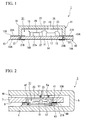
- FIG. 1 is a cross-sectional view showing the constitution of a microphone module in accordance with a first embodiment of the present invention;
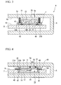
- FIG. 2 is a cross-sectional view showing a portable electronic device equipped with the microphone module;
- FIG. 3 is a cross-sectional view showing another portable electronic device equipped with the microphone module;
- FIG. 4 is a cross-sectional view showing a first variation of the portable electronic device shown in FIG. 2;
- FIG. 5 is a cross-sectional view showing a second variation of the portable electronic device shown in FIG. 2;
- FIG. 6 is a cross-sectional view showing the constitution of a microphone module in accordance with a second embodiment of the present invention;
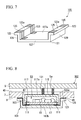
- FIG. 7 is a perspective view showing the structure of a support for mounting and supporting the microphone module shown in FIG. 6;
- FIG. 8 is a cross-sectional view showing the constitution of a portable electronic device incorporating the microphone module of FIG. 6 by way of the support shown in FIG. 7;
- FIG. 9 is a cross-sectional view showing the constitution of another portable electronic device incorporating the microphone module of FIG. 6;
- FIG. 10 is a cross-sectional view showing a first variation of the portable electronic device shown in FIG. 8; and
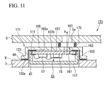
- FIG. 11 is a cross-sectional view showing a second variation of the portable electronic device shown in FIG. 8.
- The present invention will be described in further detail by way of examples with reference to the accompanying drawings.
- A
microphone module 1 according to a first embodiment of the present invention will be described with reference to FIGS. 1 to 3. - As shown in FIGS. 2 and 3, the
microphone module 1 is designed to suithousings microphone module 1 is designed in a shape, which can be mounted onmount portions circuit boards housings electronic devices 3 and 4 respectively. - As shown in FIG. 1, the
microphone module 1 includes asubstrate 11 having a rectangular shape in plan view, amicrophone chip 15 and acontrol circuit chip 17 fixed onto asurface 13 of thesubstrate 11, and acover member 19, which covers a part of thesurface 13 of thesubstrate 11 including themicrophone chip 15 and thecontrol circuit chip 17 so as to form a hollow cavity S together with thesubstrate 11. Herein, peripheral portions (or extended portions) of thesubstrate 11 are horizontally extended in opposite directions externally from the side walls of thecover member 19. - The
substrate 11 has a multilayered wiring substrate, in which a plurality ofexternal connection terminals 21 are formed on thesubstrate 11 so as to electrically connect themicrophone chip 15 and thecontrol circuit chip 17 to thecircuit board 7 or 8 (see FIGS. 2 and 3). Each of theexternal connection terminals 21 are exposed on thesurface 13 and abackside 14 of thesubstrate 11. Specifically, a first portion 2 1 A of theexternal connection terminal 21, which is exposed on thesurface 13 of thesubstrate 11, is elongated horizontally from the inside to the outside of the cavity S1. Asecond portion 21 B of theexternal connection terminal 21, which is exposed on thebackside 14 of thesubstrate 11, is positioned inward with respect to the extended portions of thesubstrate 11 extended externally from the side walls of thecover member 19. - A
sound hole 25, which allows the cavity S1 to communicate with the exterior, is formed at a prescribed position of atop portion 23 of thecover member 19 that is positioned opposite to thesurface 13 of thesubstrate 11. The opening direction A of thesound hole 25 lies vertical to thesurface 13 of thesubstrate 11. - The
microphone chip 15 is constituted such that adiaphragm 29 covers aninner hole 27a of a ring-shapedsupport 27. Thediaphragm 29 detects sound by way of vibration; hence, themicrophone chip 15 forms a sound pressure sensor that converts vibration of thediaphragm 29 into electric signals. - The
microphone chip 15 is fixed on thesurface 13 of thesubstrate 11 by use of a die bonding material (not shown) in such a way that thediaphragm 29 is positioned opposite to thesurface 13 of thesubstrate 11 via theinner hole 27a. - The
control circuit chip 17 drives and controls themicrophone chip 15. Specifically, thecontrol circuit chip 17 includes an amplifier for amplifying electric signals from themicrophone chip 15, a digital signal processor (DSP) for processing electric signals in form of digital signals, and an analog-to-digital (A/D) converter. Similar to themicrophone chip 15, thecontrol circuit chip 17 is fixed on thesurface 13 of thesubstrate 11 by use of the die bond material (not shown). - The
control circuit chip 17 is electrically connected to themicrophone chip 15 via afirst wire 31, while it is also electrically connected to the first portion 2 1 A of theexternal connection terminal 21, which is exposed inside of the cavity S1, via asecond wire 33. This makes it possible to electrically connect themicrophone chip 15 to theexternal terminal 21. - In the
microphone module 1 having the aforementioned constitution, ahousing 41 forming thecavity S 1 and thesound hole 25 is constituted of thecover member 19 and the prescribed part of thesubstrate 11 covered with thecover member 19. The extended portions of thesubstrate 11, which are extended externally from the side walls of thecover member 19, are defined asextended portions 43, which are extended from the exterior of thehousing 41 in horizontal directions perpendicular to the opening direction A of thesound hole 25. - Therefore, the
microphone module 1 has the extendedportions 43, which are reversely extended from both sides of thehousing 41, whereby thehousing 41 vertically projects fromsurfaces 13A of theextended portions 43, which correspond to thesurface 13 of thesubstrate 11. Theexternal connection terminals 21 are vertically elongated along the opening direction of thesound hole 25 from thesurfaces 13A of theextended portions 43 to thebackside 14B of thehousing 41, which is positioned opposite to thesurfaces 13A of theextended portions 43. In other words, theexternal connection terminal 21 does not exist inbacksides 14A of theextended portions 43, which correspond to thebackside 14 of thesubstrate 11. - In the manufacturing of the
microphone module 1, themicrophone chip 15 and thecontrol circuit chip 17 are fixed onto thesurface 13 of thesubstrate 11 in which theexternal connection terminals 21 are formed in advance; then, themicrophone chip 15 is electrically connected to thecontrol circuit chip 17 via thefirst wire 31, and thecontrol circuit chip 17 is electrically connected to theexternal connection terminal 21; thereafter, thecover member 19 having thesound hole 25 is fixed onto thesurface 13 of thesubstrate 11. - Next, the mounting structure of the
microphone module 1, which is mounted on the mount portion of the circuit board of themicrophone module 1, as well as a portable electronic device having the mounting structure will be described with reference to FIGS. 2 and 3. - The
housing 5 of the portableelectronic device 3 shown in FIG. 2 has asound port 5a to allow the entry of sound, and thehousing 6 of the portable electronic device 4 shown in FIG. 3 has asound port 6a to allow the entry of sound. Herein, the portableelectronic device 3 has a mounting structure for mounting themicrophone module 1 on amount portion 9 of acircuit board 7 at a prescribed position relative to thesound port 5a of thehousing 5, and the portable electronic device 4 has a mounting structure for mounting themicrophone module 1 on amount portion 10 of acircuit board 8 at a prescribed position relative to thesound port 6a of thehousing 6. These mounting structures differ from each other depending upon the positioning of themount portions - In the portable
electronic device 3 shown in FIG. 2 in which asurface 45 of thecircuit board 7 positioned opposite to themount portion 9 is directed to thesound port 5a of thehousing 5, a through-hole 47 running through thecircuit board 7 in its thickness direction is formed in advance so as to allow thehousing 41 to be inserted therein. When thehousing 41 is inserted into the through-hole 47 from themount portion 9, thesurfaces 13A of theextended portions 43 come in contact with themount portion 9 in the periphery of the through-hole 47.Connection pads 49 are formed in advance in connection with themount portion 9 in the periphery of the through-hole 47; hence, theexternal connection terminals 21 exposed on thesurfaces 13A of theextended portions 43 come in contact with theconnection pads 49 so as to establish an electrical connection between themicrophone module 1 and thecircuit board 7. In the above, themicrophone module 1 is arranged in such a way that thesound hole 25 is opened upwardly relative to thesurface 45 of thecircuit board 7 and is directed to thesound port 5a of thehousing 5 of the portableelectronic device 3. - A ring-shaped anti-sound-
leak gasket 51 is inserted between thesound hole 25 and thesound port 5a, whereby it prevents sound, which is introduced into thehousing 5 via thesound port 5a, from dispersing inside of thehousing 5; thus, it is possible to efficiently propagate sound into thecavity S 1. The shape of the anti-sound-leak gasket 51 is not necessarily limited to the ring shape but can be arbitrarily designed in any shape suiting the shaping of thesound hole 25 and thesound port 5a. - In FIG. 2, the exterior of the
top portion 23 of themicrophone module 1 forming thesound hole 25 is placed substantially in the same plane as thesurface 45 of thecircuit board 7; but this is not a restriction. For example, thetop portion 43 of themicrophone module 1 can be placed at a position that is lower than thesurface 45 of thecircuit board 7, or it can be placed at a position projecting from thesurface 45 of thecircuit board 7. - In the portable electronic device 4 shown in FIG. 3 in which the
mount portion 10 of thecircuit board 8 is positioned opposite to thesound port 6a of thehousing 6, it is unnecessary to form the through-hole 47, wherein themicrophone module 1 is mounted on thecircuit board 8 under the condition in which thebackside 14B of thehousing 41 is positioned opposite to themount portion 10 of thecircuit board 8 having theconnection pad 49. This makes it possible for thesecond portion 21 B of theexternal connection terminal 21, which is exposed on thebackside 14B of thehousing 41, to come in contact with theconnection pad 49, thus establishing an electrical connection between themicrophone module 1 and thecircuit board 8. Thesound hole 25 of themicrophone module 1 is opened upwardly above themount portion 10 of thecircuit board 8 so as to directly face thesound port 6a of thehousing 6. - In the above, a ring-shaped anti-sound-
leak gasket 53 is not directly held between thesound hole 25 of themicrophone module 1 and thesound port 6a of thehousing 6 but is directly attached to themicrophone module 1. That is, thehousing 41 of themicrophone module 1, which vertically projects from thesurfaces 13A of theextended portions 43 of thesubstrate 11, is inserted into the ring-shaped anti-sound-leak gasket 53 so that the lower portion of the anti-sound-leak gasket 53 is brought into contact with thesurfaces 13A of theextended portions 43 of thesubstrate 11. Herein, the interior of the anti-sound-leak gasket 53 is shaped to substantially match the shape of thehousing 41. - The aforementioned structure makes it easy to establish the prescribed positioning between the
microphone module 1 and the anti-sound-leak gasket 53. Since the upper portion of the anti-sound-leak gasket 53 must be brought into contact with aninterior surface 6b of thehousing 6, the upper portion of the anti-sound-leak gasket 53 projects upwardly from the exterior of thetop portion 23 of thehousing 41 when themicrophone module 1 is fixed into the portable electronic device 4. - When the
microphone module 1 is installed in the portableelectronic device 3 by use of the aforementioned mounting structure shown in FIG. 2, thehousing 41 is inserted into and engaged with the through-hole 47 of thecircuit board 7; hence, it is possible to reduce the projection height of themicrophone module 1 projecting from themount portion 9 of thecircuit board 7. This prevents themicrophone module 1 from disturbing parts of the portableelectronic device 3 even when thecircuit board 7 is arranged inside of thehousing 5 of the portableelectronic device 3; hence, it is possible to easily increase the degree of freedom in designing the portableelectronic device 3. In addition, it is possible to easily reduce the thickness of the portableelectronic device 3 including thecircuit board 7. - Due to the insertion of the
housing 41 into the through-hole 47 of thecircuit board 7, it is possible to avoid the positional deviation of themicrophone module 1 relative to thecircuit board 7; hence, it is possible to improve the mounting strength (or packaging strength) of themicrophone module 1 mounted on thecircuit board 7. - In the portable electronic device 4 shown in FIG. 3 in which the
microphone module 1 is mounted on thecircuit board 8 in such a way that thebackside 14B of thehousing 41 is positioned opposite to themount portion 10 of thecircuit board 8, it is possible to attach the anti-sound-leak gasket 53 to themicrophone module 1 in advance before themicrophone module 1 is mounted on thecircuit board 8. In other words, it is unnecessary to attach the anti-sound-leak gasket 53 to themicrophone module 1 after themicrophone module 1 is mounted on thecircuit board 8. Thus, it is possible to maintain a reliable electrical connection between themicrophone module 1 and thecircuit board 8. - As described above, in the portable
electronic device 3 shown in FIG. 2, themicrophone module 1 is mounted on thecircuit board 7 in such a way that surfaces 13A of theextended portions 43 are positioned opposite to themount surface 9. Alternatively, in the portable electronic device 4 shown in FIG. 3, themicrophone module 1 is mounted on thecircuit board 8 in such a way that thebackside 14B of thehousing 41 is positioned opposite to themount portion 10. This improves the degree of freedom in mounting themicrophone module 1 on thecircuit boards electronic devices 3 and 4. - The
microphone module 1 is constituted of thesubstrate 11 and thecover member 19, wherein thefirst portion 21A and thesecond portion 21B of theexternal connection terminal 21, which is used to establish an electrical connection with thecircuit boards substrate 11 only. This makes it possible to produce themicrophone module 1 with ease. - The first embodiment is designed such that the
sound hole 25 is formed on thetop portion 23 of thecover member 19; but this is not a restriction. That is, it is simply required that thehousing 41 be constituted of at least a part of thesubstrate 11 and thecover member 19, and the opening direction of thesound hole 25 be perpendicular to theextended portions 43 of thesubstrate 11. For this reason, the portableelectronic device 3 shown in FIG. 2 can be modified in a variety of ways. - FIG. 4 shows a first variation of the portable
electronic device 3 incorporating amicrophone module 61, in which asound hole 55 is formed to run through thesubstrate 11 in its thickness direction so as to allow thecavity S 1 to communicate the exterior. In this case, thesurfaces 13A of theextended portions 43 lie opposite to and along the opening direction B of thesound hole 55. - In FIG. 4, the
microphone module 61 having thesound hole 55, which is opened in thebackside 14 of thesubstrate 11, is installed in the portableelectronic device 3 in such a way that thesurfaces 13A of theextended portions 43 are positioned opposite to themount portion 9 of thecircuit board 7. Similar to the portableelectronic device 3 shown in FIG. 2, it is necessary to form the through-hole 47 for the insertion of thehousing 41 in thecircuit board 7. When themicrophone module 61 is modified such that thebackside 14 of thesubstrate 11 is positioned opposite to themount portion 9 of thecircuit board 7, it is necessary to form another through-hole (not shown) allowing thesound hole 55 to be opened with the exterior. - In the first embodiment, the
external terminals 21 are formed on thebackside 14B of thehousing 41; but this is not a restriction. For example, theexternal connection terminals 21 can be formed on thebackside 14A of theextended portions 43; or they can be formed on thebacksides 14A of theextended portions 43 as well as thebackside 14B of thesubstrate 11. - The
external connection terminals 21, which are electrically connected to themicrophone chip 15, are not necessarily formed on thebacksides 14A of theextended portions 43 and thebackside 14B of thesubstrate 11; that is, they can be formed on only thesurfaces 13A of theextended portions 43. This modification allows thehousing 41 to be reliably inserted into the through-hole 47 of thecircuit board 17; hence, it is possible to reduce the projection height of themicrophone module mount portion 9 of thecircuit board 7. - In the first embodiment, the
microphone module 1 is constituted of thesubstrate 11 and thecover member 9; but this is not a restriction. FIG. 5 shows a second variation of the portableelectronic device 3 incorporating amicrophone module 71, which is constituted of aresin mold 73, acover board 75, and a plurality of leads 77. - The
resin mold 73 is constituted of a bottom 79 having a rectangular shape in plan view and aside wall 81 that projects vertically from the periphery of asurface 79a of the bottom 79. Themicrophone chip 15 and thecontrol circuit chip 17 are fixed onto thesurface 79a of the bottom 79. - The
cover board 75 is fixed to the upper end of theside wall 81 and is thus positioned opposite to thesurface 79a of the bottom 79. Thecover board 75 joins theresin mold 73 so as to form a hollow cavity S2. Asound hole 83 is formed to run through thecover member 75 in its thickness direction so as to allow the cavity S2 to communicate the exterior. Thesound hole 83 has an opening direction C perpendicular to thesurface 79a of the bottom 79. - The leads 77 are each composed of a metal material having conductivity. The leads 77 are sealed with the
resin mold 73 in such a way that the first ends thereof are exposed in the cavity S2, and the second ends thereof are extended from the side portion of themold resin 73. - The
control circuit chip 17 is electrically connected to the first end of thelead 77 via thesecond wire 33, thus allowing themicrophone chip 15 to be electrically connected to thelead 77. In themicrophone module 71, the prescribed portions of theresin mold 73 project externally fromsurfaces 77A at the second ends of theleads 77, whilebacksides 77B of the second ends of theleads 77 are formed in substantially the same plane as abackside 79b of theresin mold 73. - In the aforementioned constitution, a
housing 85 including the cavity S2 and thesound hole 83 is formed using theresin mold 73 and thecover board 75.Extended portions 87, which are extended from thehousing 85 in a horizontal direction perpendicular to the opening direction C of thesound hole 83, are formed using the extended portions of theleads 77, which are extended from theresin mold 73. The leads 77 serve as external connection terminals that are electrically connected to themicrophone chip 15. - Similar to the
microphone module 1, themicrophone module 71 having the aforementioned constitution can be mounted on themount portion 9 of thecircuit board 7 that is positioned relative to thesound port 5a of thehousing 5. - For example, when the
opposite surface 45 of thecircuit board 7 is directed toward thesound port 5a of thehousing 5, thehousing 85 is inserted into the through-hole 47 of thecircuit board 7 from themount portion 9, so that thesurfaces 77A of theleads 77, which are extended from theresin mold 73, come in contact with theconnection pads 49 formed on the periphery of the through-hole 47, thus establishing electric connection with thecircuit board 7. In this state, themicrophone module 71 is installed in the portable electronic device such that thesound hole 83 is opened upwardly above theopposite surface 45 of thecircuit board 7 so as to directly face thesound port 5a of thehousing 5. - The
microphone module 71 offers effects similar to those of themicrophone modules microphone module 71, which is formed by sealing the leads 77 (serving as the external connection terminals and the extended portions 87) with theresin mold 73. - In the
microphone modules housings surfaces extended portions backsides extended portions - Next, a
microphone module 101 according to a second embodiment of the present invention will be described in detail with reference to FIGS. 6 to 9, wherein parts identical to those of themicrophone module 1 as well as parts identical to those of the portableelectronic devices 3 and 4 are designated by the same reference numerals; hence, the descriptions thereof will be omitted as necessary. - As shown in FIG. 6, the
microphone module 101 is constituted of amain body 103 and asupport 105 for mounting and supporting themain body 103. - The
main body 103 of themicrophone module 101 is constituted of asubstrate 107 having a rectangular shape in plan view, themicrophone chip 15 and thecontrol circuit chip 17 both fixed onto asurface 107a of thesubstrate 107, and acover member 109 that entirely covers thesurface 107a of thesubstrate 107 including themicrophone chip 15 and thecontrol circuit chip 17 so as to form a hollow cavity S3 with thesubstrate 107. - The
substrate 107 is a multilayered wiring substrate, in which a plurality ofexternal connection terminals 111 are formed to electrically connect themicrophone chip 15 and thecontrol circuit chip 17, which are arranged inside of the cavity S3, to thecircuit boards external connection terminals 111 are each exposed on both of thesurface 107a and abackside 107b of thesubstrate 107, wherein the prescribed portions of theexternal connection terminals 111 exposed on thesurface 107a of thesubstrate 107 are exposed inside of the cavity S3. - A
sound hole 115 allowing the cavity S3 to communicate the exterior is formed at a prescribed position of atop portion 113 of thecover member 109, which is positioned opposite to thesurface 107a of thesubstrate 107. The opening direction D of thesound hole 115 is perpendicular to thesurface 107a of thesubstrate 107. - A
housing 117 having the cavity S3 and thesound hole 115 is formed using thesubstrate 107 and thecover member 109. Herein, thebackside 107b of thesubstrate 107 forms the backside of thehousing 117, and the exterior surface of thetop portion 113 having thesound hole 115 forms asurface 117a of thehousing 117. - As shown in FIGS. 6 and 7, the
support 105 is constituted of amount portion 121 for mounting themain body 103 of themicrophone module 101, a pair ofextended portions 123, which are extended horizontally from themount portion 121 in a direction perpendicular to the opening direction D of thesound hole 115, and a plurality ofintermediate connection terminals 125, which are elongated from themount portion 121 to theextended portions 123. - The
mount portion 121 is constituted of amount area 127a having a rectangular shape in plan view, on which themain body 103 of themicrophone module 101 is mounted opposite to thebackside 107b of thesubstrate 107, and a pair ofside walls 129 that vertically project from both ends of themount area 127a. Hence, themain body 103 of themicrophone module 101 is precisely mounted on themount area 127a defined between theside walls 129. Theextended portions 123 are extended outwardly from the upper ends of theside walls 129; hence, they are positioned externally of themount area 127a in plan view. - The
intermediate connection terminals 125 are formed at the prescribed positions in contact with theexternal connection terminals 111 under the condition in which themain body 103 of themicrophone module 101 is mounted on themount area 127a of themount portion 121. Themain body 103 of themicrophone module 101 is fixed to thesupport 105 in such a way that thebackside 107b of thehousing 117 is positioned opposite to themount area 127a of themount portion 121, thus electrically connecting theexternal connection terminals 111 to theintermediate connection terminals 125. Incidentally, theintermediate connection terminals 125 are each horizontally extended along themount area 127a, vertically elongated along theside walls 129, and horizontally elongated alongsurfaces 123a of theextended portions 123, which are vertically elevated from themount area 127a and which are horizontally extended externally of and in parallel with themount area 127a. - Heights of the
surfaces 123a of theextended portions 123 measured from themount area 127a are determined such that they are lower than the height of themain body 103 of themicrophone module 101 mounted on themount area 127a. - Next, a mounting structure for mounting the
microphone module 101 on thecircuit board 7 as well as a portableelectronic device 102 incorporating themicrophone module 101 will be described with reference to FIG. 8. - In FIG. 8, the
microphone module 101 is mounted on themount portion 9 of thecircuit board 7 installed in the portableelectronic device 102 in such a way that theopposite surface 45 of thecircuit board 7 opposite to themount portion 9 is directed toward thesound port 5a of thehousing 5. That is, when thehousing 117 of themicrophone module 101 is inserted into the through-hole 47 from themount portion 9 of thecircuit board 7, thesurfaces 123a of theextended portions 123 come in contact with themount portion 9 in the periphery of the through-hole 47. Since theconnection pads 49 are formed on themount portion 9 in the periphery of the through-hole 47, theintermediate connection terminals 125 formed on thesurfaces 123a of theextended portions 123 are brought into contact with theconnection pads 49, thus establishing an electrical connection between thecircuit board 7 and the external connection terminals of themain body 103 of themicrophone module 101. - In the above, the
microphone module 101 is mounted on thecircuit board 7 in such a way that thesurface 117a of thehousing 117 is directed to themount portion 9; hence, thesound hole 115 of themicrophone module 101 is opened vertically relative to theopposite surface 45 of thecircuit board 7 so as to directly face thesound port 5a of thehousing 5 of the portableelectronic device 102. - A ring-shaped anti-sound-
leak gasket 131 is held between thesound hole 115 and thesound port 5a, which are positioned opposite to each other. Thus, it is possible to prevent sound, which is introduced into thehousing 5 via thesound port 5a, from being dispersed inside of thehousing 5; that is, the ring-shaped anti-sound-leak gasket 131 makes it possible to efficiently propagate sound into the cavity S3. - In FIG. 8, the
surface 117a of thehousing 117 of themicrophone module 101 is lower than theopposite surface 45 of thecircuit board 7; but this is not a restriction. That is, thesurface 117a of thehousing 117 can be placed substantially in the same plane with theopposite surface 45 of thecircuit board 7; alternatively, it can be placed higher than theopposite surface 45 of thecircuit board 7. - FIG. 9 shows a portable
electronic device 104 in which themicrophone module 101 is mounted on thecircuit board 8 whosemount portion 10 is directed to thesound port 6a of thehousing 6, wherein themain body 103 of themicrophone module 101 is removed from thesupport 105, which is not necessarily used, and is thus reliably mounted on thecircuit board 8. - In the above, the through-
hole 47 is not necessary so that themain body 103 of themicrophone module 101 is simply mounted on thecircuit board 8 under the condition in which thebackside 107b of thehousing 117 is positioned opposite to themount portion 10 having theconnection pads 49. Herein, theexternal connection terminals 111 exposed on thebackside 107b of thehousing 117 are brought into contact with theconnection pads 49, thus establishing an electrical connection between themicrophone module 101 and thecircuit board 8. Herein, themicrophone module 101 is installed in the portableelectronic device 104 in such a way that thesound hole 115 is opened above themount portion 10 of thecircuit board 8 so as to directly face thesound port 6a of thehousing 6. - In FIG. 8, similar to the
microphone module 1, themicrophone module 101, which is installed in the portableelectronic device 102 by way of the aforementioned mounting structure, is arranged in such a way that thehousing 117, which vertically projects above thesurfaces 123a of theextended portions 123, is inserted into and engaged with the through-hole 47 of thecircuit board 7, wherein it is possible to reduce the projection height of themicrophone module 101, which vertically projects from themount portion 9 of thecircuit board 7. - Due to the insertion of the
housing 117 into the through-hole 47 of thecircuit board 7, it is possible to reliably avoid the positional deviation of themicrophone module 101 relative to thecircuit board 7; hence, it is possible to improve the mounting strength (or packaging strength) of themicrophone module 101 mounted on thecircuit board 7. - As shown in FIGS. 8 and 9, the
main body 103 of themicrophone module 101, which is detached from thesupport 105, can be reliably and easily mounted on thecircuit board housing 117. Thus, it is possible to improve the degree of freedom in mounting themicrophone module 101 on thecircuit boards electronic devices - In the second embodiment, the
main body 103 of themicrophone module 101, which is mounted on themount area 127a of themount portion 121, vertically projects above thesurfaces 123a of theextended portions 123; but this is not a restriction. For example, as shown in FIG. 10, a support 141 is designed to completely incorporate themain body 103 of themicrophone module 101 within amount portion 143. Herein, thesurfaces 123a of theextended portions 123 can be adjusted in height in such a way that they are substantially placed in the same plane as thesurface 117a of thehousing 117 having thesound hole 115. Alternatively, the heights of thesurfaces 123a of theextended portions 123 are higher than the height of themain body 103 of themicrophone module 101. - FIG. 10 shows a potable
electronic device 155 incorporating amicrophone module 145, which is mounted on acircuit board 147 in such a way that thesurface 117a of thehousing 117 is directed to amount portion 149 of thecircuit board 147. In this case, it is necessary to form a through-hole 151, which allows asound hole 115 to communicate with the exterior, in thecircuit board 147. Due to the aforementioned constitution of themicrophone module 145 mounted on thecircuit board 147, even when anopposite surface 153 of thecircuit board 147 is positioned opposite to thesound port 6a of thehousing 6, thesound hole 115 can directly face thesound port 6a via the through-hole 151 of thecircuit board 147. In the portableelectronic device 155, it is preferable that an anti-sound-leak gasket 157 be arranged between thesound port 6a of thehousing 6 and the through-hole 151 of thecircuit board 147, which are positioned opposite to each other. - As shown in FIG. 7, the
mount portion 121 for mounting themicrophone module 101 is constituted of the bottom 127 having a rectangular shape in plan view and theside walls 129 that vertically project from both ends of the bottom127; but this is not a restriction. That is, themount portion 121 can be simply formed using the bottom 127 only. In this modification, theextended portions 123 are directly and horizontally extended from the periphery of the bottom 127. In short, this modification indicates that thesupport 105 is formed substantially in a rectangular shape, wherein when themain body 103 of themicrophone module 101 is fixed onto themount portion 121, thehousing 117 entirely projects from thesurfaces 123a of theextended portions 123. - In the aforementioned modification, the
microphone module 101 can be mounted on the circuit board while thehousing 117 is inserted into the through-hole of the circuit board; hence, it is possible to further reduce the projection height of themicrophone module 101 vertically projecting from the mount portion of the circuit board. - In the
mount portion 121, theintermediate connection terminals 125 are elongated onto thesurfaces 123a of theextended portions 123; alternatively, they can be elongated onto the backsides of theextended portions 123, or they can be elongated onto the backside of the bottom 127 opposite to themount area 127a. In this modification, themain body 103 of themicrophone module 101 is unnecessarily removed from thesupport 105, wherein thesurface 117a of thehousing 117 having thesound hole 115 can be easily arranged on both of themount portion 9 andopposite surface 45 of thecircuit board 7. - The
external connection terminals 111 of themain body 103 of themicrophone module 101 are exposed on thebackside 107b of thehousing 117 along the opening direction of thesound hole 115; but this is not a restriction. FIG. 11 shows a portableelectronic device 173 incorporating amicrophone module 171 whosemain body 103 is mounted on themount portion 9 of thecircuit board 7 by way of asupport 163, wherein they are exposed on thebackside 107b of thehousing 117 having asound hole 161 lying along an opening direction E. That is, thesound hole 161 is formed at a prescribed position of asubstrate 107 having thebackside 107b, on which theexternal connection terminals 111 are exposed. - When the
main body 103 of themicrophone module 171, in which thesound hole 161 is opened on thebackside 107b of thesubstrate 107, is mounted on amount area 165a of thesupport 163, thesound hole 161 is exposed to communicate the exterior via aninterconnection hole 167 running through a bottom 165 in its thickness direction. - When the
microphone module 171 is installed in the portableelectronic device 173, it is necessary to insert agasket 175 between theinterconnection hole 167 of thesupport 163 and thesound port 5a of thehousing 5. - When the heights of the
surfaces 123a of theextended portions 123, which are positioned opposite to amount portion 165a of thesupport 163, is lower than the height of themain body 103 of themicrophone module 171, it is necessary to form the through-hole 47 for use in the insertion of thehousing 117 in thecircuit board 7 on which themicrophone module 171 is mounted. - In the
microphone modules surfaces extended portions mount portion 9 of thecircuit board 7, it is necessary to form the through-hole 47 running through thecircuit board 7 in its thickness direction; but this is not a restriction. That is, the first and second embodiments require that at least a recess be formed in themount portion 9 of thecircuit board 7 so as to enable the insertion of thehousings housings surfaces extended portions - Lastly, the present invention is not necessarily limited to the aforementioned embodiments, which can be further modified within the scope of the invention defined by the appended claims.
Claims (8)
- A microphone module comprising:a housing having a hollow cavity and a sound hole, via which the hollow cavity communicates an exterior;a microphone chip for detecting sound, which is arranged inside of the hollow cavity;a plurality of external connection terminals that are electrically connected to the microphone chip; anda plurality of extended portions that are horizontally extended from both ends of the housing in a direction perpendicular to an opening direction of the sound hole,wherein the plurality of external connection terminals are each elongated onto a surface or a backside of the extended portions, and
wherein the housing partially projects from the surfaces of the extended portions. - A microphone module according to claim 1, wherein the plurality of external connection terminals are each elongated onto a backside of the housing, which is positioned opposite to the surfaces of the extended portions.
- A microphone module according to claim 1, wherein the housing is constituted of a substrate for fixedly mounting the microphone chip on a surface thereof and a cover member that covers the surface of the substrate so as to form the hollow cavity, and wherein the extended portions are formed using the substrate and are extended externally of the cover member.
- A microphone module according to claim 1, wherein the plurality of extended portions are formed using a plurality of leads, each having a conductivity, which serve as the plurality of external connection terminals, and wherein the housing is formed using a resin mold for sealing the plurality of leads.
- A microphone module comprising:a main body, which is constituted of a housing having a hollow cavity, a microphone chip that is arranged inside of the hollow cavity so as to detect sound, and a plurality of external connection terminals that are each electrically connected to the microphone chip, wherein the housing has a sound hole for communicating the hollow cavity to an exterior, and wherein the plurality of external connection terminals are each elongated onto a backside of the housing in a direction perpendicular to an opening direction of the sound hole; anda support for mounting and supporting the main body, wherein the support is constituted of a mount portion that is positioned opposite to the backside of the housing so as to mount the main body, a plurality of extended portions that are horizontally extended externally from the mount portion in a direction perpendicular to the opening direction of the sound hole, and a plurality of intermediate connection terminals that are elongated from the mount portion to the extended portions, andwherein the intermediate connection terminals are elongated onto surfaces of the extended portions lying in parallel with the mount portion.
- A microphone module according to claim 5, wherein heights of the surfaces of the extended portions measured from the mount portion are lower than a height of the main body mounted on the mount portion.
- A mounting structure for mounting a microphone module on a mount portion of a circuit board, wherein the microphone module includes a housing having a hollow cavity and a sound hole for communicating the hollow cavity with an exterior, a microphone chip that is arranged inside of the hollow cavity so as to detect sound, a plurality of extended portions that are horizontally extended from the housing in a direction perpendicular to an opening direction of the sound hole, and a plurality of connection terminals that are formed in the extended portions and are electrically connected to the microphone chip, and wherein when the housing is inserted into a hole running through the mount portion of the circuit board, the extended portions come in contact with the mount portion so that the plurality of connection terminals come in contact with a plurality of connection pads formed on the mount portion of the circuit board, thus establishing an electrical connection between the microphone module and the circuit board.
- A portable electronic device in which a microphone module is mounted on a mount portion of a circuit board incorporated in a housing, wherein the microphone module includes a housing having a hollow cavity and a sound hole for communicating the hollow cavity with an exterior, a microphone chip that is arranged inside of the hollow cavity so as to detect sound, a plurality of extended portions that are horizontally extended from the housing in a direction perpendicular to an opening direction of the sound hole, and a plurality of connection terminals that are formed in the extended portions and are electrically connected to the microphone chip, and wherein when the housing is inserted into a hole running through the mount portion of the circuit board, the extended portions come in contact with the mount portion so that the plurality of connection terminals come in contact with a plurality of connection pads formed on the mount portion of the circuit board, thus establishing an electrical connection between the microphone module and the circuit board.
Applications Claiming Priority (1)
| Application Number | Priority Date | Filing Date | Title |
|---|---|---|---|
| JP2006244268A JP2008067173A (en) | 2006-09-08 | 2006-09-08 | Microphone module, its attaching structure and mobile electronic device |
Publications (2)
| Publication Number | Publication Date |
|---|---|
| EP1901579A2 true EP1901579A2 (en) | 2008-03-19 |
| EP1901579A3 EP1901579A3 (en) | 2009-10-14 |
Family
ID=39004803
Family Applications (1)
| Application Number | Title | Priority Date | Filing Date |
|---|---|---|---|
| EP07017239A Withdrawn EP1901579A3 (en) | 2006-09-08 | 2007-09-03 | Microphone module and mounting structure adapted to portable electronic device |
Country Status (6)
| Country | Link |
|---|---|
| US (1) | US20080123891A1 (en) |
| EP (1) | EP1901579A3 (en) |
| JP (1) | JP2008067173A (en) |
| KR (1) | KR20080023144A (en) |
| CN (1) | CN101141828A (en) |
| TW (1) | TW200826716A (en) |
Cited By (3)
| Publication number | Priority date | Publication date | Assignee | Title |
|---|---|---|---|---|
| US8340735B2 (en) | 2010-08-06 | 2012-12-25 | Research In Motion Limited | Electromagnetic shielding and an acoustic chamber for a microphone in a mobile electronic device |
| EP2357844A4 (en) * | 2008-12-12 | 2013-10-30 | Funai Electric Co | MICROPHONE UNIT AND VOICE INPUT DEVICE USING THE SAME |
| EP2416544B1 (en) * | 2010-08-06 | 2015-04-29 | BlackBerry Limited | Electromagnetic Shielding and an Acoustic Chamber for a Microphone in a Mobile Electronic Device |
Families Citing this family (32)
| Publication number | Priority date | Publication date | Assignee | Title |
|---|---|---|---|---|
| US8306252B2 (en) * | 2007-01-05 | 2012-11-06 | Apple Inc. | Integrated microphone assembly for personal media device |
| US8126138B2 (en) | 2007-01-05 | 2012-02-28 | Apple Inc. | Integrated speaker assembly for personal media device |
| US8290546B2 (en) | 2009-02-23 | 2012-10-16 | Apple Inc. | Audio jack with included microphone |
| US8280080B2 (en) * | 2009-04-28 | 2012-10-02 | Avago Technologies Wireless Ip (Singapore) Pte. Ltd. | Microcap acoustic transducer device |
| US8571249B2 (en) * | 2009-05-29 | 2013-10-29 | General Mems Corporation | Silicon microphone package |
| JP2011055300A (en) * | 2009-09-02 | 2011-03-17 | Fujitsu Ltd | Portable terminal device |
| JP2011114506A (en) * | 2009-11-26 | 2011-06-09 | Funai Electric Co Ltd | Microphone unit |
| US20120025335A1 (en) * | 2010-07-28 | 2012-02-02 | Avago Technologies Wireless Ip (Singapore) Pte. Ltd. | Microelectromechanical systems (mems) package |
| US20120161258A1 (en) | 2010-12-28 | 2012-06-28 | Loeppert Peter V | Package with a cmos die positioned underneath a mems die |
| CN102572036B (en) * | 2010-12-28 | 2014-07-09 | 歌尔声学股份有限公司 | Electronic product |
| DE112010006098T5 (en) * | 2010-12-28 | 2014-03-20 | Knowles Electronics, Llc | Package with a arranged under a MEMS chip CMOS chip |
| CN102740186A (en) * | 2011-03-31 | 2012-10-17 | 英业达股份有限公司 | Audio interface structure and electronic device using the structure |
| US9066172B2 (en) | 2012-09-28 | 2015-06-23 | Apple Inc. | Acoustic waveguide and computing devices using same |
| US10097918B2 (en) | 2013-01-23 | 2018-10-09 | Infineon Technologies Ag | Chip arrangement and a method for manufacturing the same |
| US9380369B2 (en) | 2013-02-14 | 2016-06-28 | Apple Inc. | Microphone seal |
| JP6175261B2 (en) * | 2013-03-27 | 2017-08-02 | 京セラ株式会社 | Electronic equipment with microphone |
| US9942655B2 (en) * | 2013-09-20 | 2018-04-10 | Infineon Technologies Ag | Sound processing |
| GB2521448B (en) * | 2013-12-20 | 2021-07-21 | Nokia Technologies Oy | An apparatus and method for providing an apparatus comprising a covering portion for an electronic device |
| US10812900B2 (en) | 2014-06-02 | 2020-10-20 | Invensense, Inc. | Smart sensor for always-on operation |
| CN105916084B (en) * | 2015-02-23 | 2019-11-12 | 因文森斯公司 | The intelligence sensor of always-on operation |
| US10281485B2 (en) | 2016-07-29 | 2019-05-07 | Invensense, Inc. | Multi-path signal processing for microelectromechanical systems (MEMS) sensors |
| US10271121B2 (en) * | 2016-09-23 | 2019-04-23 | Apple Inc. | Shock mounted transducer assembly |
| EP3593221A4 (en) | 2017-04-24 | 2020-10-28 | Hewlett-Packard Development Company, L.P. | MICROPHONE MODULE FOR COMPUTING DEVICE |
| JP6635605B2 (en) * | 2017-10-11 | 2020-01-29 | 国立研究開発法人理化学研究所 | Current introduction terminal, pressure holding device and X-ray imaging device having the same |
| TWM574274U (en) * | 2018-08-20 | 2019-02-11 | 和碩聯合科技股份有限公司 | Radio electronic device and its radio structure |
| KR102167493B1 (en) * | 2018-11-20 | 2020-10-19 | 주식회사 이엠텍 | Actuator |
| CN115668983B (en) | 2020-04-22 | 2025-08-26 | 哈曼国际工业有限公司 | Microelectromechanical System (MEMS) microphone assembly |
| KR102775396B1 (en) * | 2020-08-04 | 2025-03-04 | 삼성전자주식회사 | Electronic device including microphone module |
| JP7858261B2 (en) * | 2021-02-03 | 2026-05-14 | ホシデン株式会社 | Microphone unit |
| US12225146B2 (en) | 2021-03-02 | 2025-02-11 | Apple Inc. | Acoustic module for handheld electronic device |
| US11962960B2 (en) * | 2021-07-19 | 2024-04-16 | Samsung Electronics Co., Ltd. | Electronic device including sound component assembly |
| US11863925B2 (en) | 2021-10-12 | 2024-01-02 | Harman International Industries, Incorporated | Apparatus and method for MEMS microphone performance via back volume |
Family Cites Families (6)
| Publication number | Priority date | Publication date | Assignee | Title |
|---|---|---|---|---|
| DE10142655A1 (en) * | 2001-08-31 | 2003-04-03 | Epcos Ag | component assembly |
| JP2004135223A (en) * | 2002-10-15 | 2004-04-30 | Hosiden Corp | Condenser microphone and manufacturing method therefor |
| US7382048B2 (en) * | 2003-02-28 | 2008-06-03 | Knowles Electronics, Llc | Acoustic transducer module |
| EP1722596A4 (en) * | 2004-03-09 | 2009-11-11 | Panasonic Corp | ELECTRET CONDENSER MICROPHONE |
| KR100712149B1 (en) * | 2004-04-27 | 2007-04-27 | 호시덴 가부시기가이샤 | Electret-condenser microphone |
| SG130158A1 (en) * | 2005-08-20 | 2007-03-20 | Bse Co Ltd | Silicon based condenser microphone and packaging method for the same |
-
2006
- 2006-09-08 JP JP2006244268A patent/JP2008067173A/en active Pending
-
2007
- 2007-09-03 EP EP07017239A patent/EP1901579A3/en not_active Withdrawn
- 2007-09-05 KR KR1020070089828A patent/KR20080023144A/en not_active Ceased
- 2007-09-06 TW TW096133304A patent/TW200826716A/en unknown
- 2007-09-06 CN CNA2007101472993A patent/CN101141828A/en active Pending
- 2007-09-06 US US11/899,578 patent/US20080123891A1/en not_active Abandoned
Cited By (5)
| Publication number | Priority date | Publication date | Assignee | Title |
|---|---|---|---|---|
| EP2357844A4 (en) * | 2008-12-12 | 2013-10-30 | Funai Electric Co | MICROPHONE UNIT AND VOICE INPUT DEVICE USING THE SAME |
| US8823115B2 (en) | 2008-12-12 | 2014-09-02 | Funai Electric Co., Ltd. | Microphone unit and voice input device using same |
| US8340735B2 (en) | 2010-08-06 | 2012-12-25 | Research In Motion Limited | Electromagnetic shielding and an acoustic chamber for a microphone in a mobile electronic device |
| US8918150B2 (en) | 2010-08-06 | 2014-12-23 | Blackberry Limited | Electromagnetic shielding and an acoustic chamber for a microphone in a mobile electronic device |
| EP2416544B1 (en) * | 2010-08-06 | 2015-04-29 | BlackBerry Limited | Electromagnetic Shielding and an Acoustic Chamber for a Microphone in a Mobile Electronic Device |
Also Published As
| Publication number | Publication date |
|---|---|
| TW200826716A (en) | 2008-06-16 |
| KR20080023144A (en) | 2008-03-12 |
| JP2008067173A (en) | 2008-03-21 |
| CN101141828A (en) | 2008-03-12 |
| EP1901579A3 (en) | 2009-10-14 |
| US20080123891A1 (en) | 2008-05-29 |
Similar Documents
| Publication | Publication Date | Title |
|---|---|---|
| US20080123891A1 (en) | Microphone module and mounting structure adapted to portable electronic device | |
| US10257610B2 (en) | Microphone module with sound pipe | |
| US8625832B2 (en) | Packages and methods for packaging microphone devices | |
| US7560811B2 (en) | Semiconductor device | |
| US9998812B2 (en) | Surface mountable microphone package, a microphone arrangement, a mobile phone and a method for recording microphone signals | |
| US8520878B2 (en) | Microphone unit | |
| JP2008187607A (en) | Semiconductor device | |
| KR100966681B1 (en) | Semiconductor device, lead frame and its microphone package | |
| US20100322451A1 (en) | MEMS Microphone | |
| KR20090013067A (en) | Semiconductor device, preliminary mold package, and manufacturing method thereof | |
| JP2009038053A (en) | Semiconductor sensor device | |
| US8155366B2 (en) | Transducer package with interior support frame | |
| WO2025236683A1 (en) | Combined sensor and smart wearable device | |
| CN117294977A (en) | Sensor packaging structure, sensor and electronic equipment | |
| JPH0983623A (en) | Fitting structure for close-talking microphone | |
| JP2007060389A (en) | Silicon microphone package | |
| CN219981037U (en) | MEMS microphones and electronic equipment | |
| CN211089966U (en) | MEMS microphone and electronic equipment | |
| CN217389002U (en) | MEMS vibration sensor | |
| JP2009055082A (en) | Microphone package | |
| CN213186451U (en) | Microphone and electronic device | |
| CN115426603B (en) | Microphones and electronic equipment | |
| CN113905318B (en) | Microphone structure | |
| CN112118522A (en) | MEMS microphone | |
| CN219627855U (en) | Microphone assembly and electronic device |
Legal Events
| Date | Code | Title | Description |
|---|---|---|---|
| PUAI | Public reference made under article 153(3) epc to a published international application that has entered the european phase |
Free format text: ORIGINAL CODE: 0009012 |
|
| AK | Designated contracting states |
Kind code of ref document: A2 Designated state(s): AT BE BG CH CY CZ DE DK EE ES FI FR GB GR HU IE IS IT LI LT LU LV MC MT NL PL PT RO SE SI SK TR |
|
| AX | Request for extension of the european patent |
Extension state: AL BA HR MK YU |
|
| PUAL | Search report despatched |
Free format text: ORIGINAL CODE: 0009013 |
|
| AK | Designated contracting states |
Kind code of ref document: A3 Designated state(s): AT BE BG CH CY CZ DE DK EE ES FI FR GB GR HU IE IS IT LI LT LU LV MC MT NL PL PT RO SE SI SK TR |
|
| AX | Request for extension of the european patent |
Extension state: AL BA HR MK RS |
|
| AKX | Designation fees paid | ||
| STAA | Information on the status of an ep patent application or granted ep patent |
Free format text: STATUS: THE APPLICATION IS DEEMED TO BE WITHDRAWN |
|
| 18D | Application deemed to be withdrawn |
Effective date: 20100415 |
|
| REG | Reference to a national code |
Ref country code: DE Ref legal event code: 8566 |