EP1901465B1 - Verfahren zur aufwärtsstrecken-synchronisationsherstellung auf der basis der vereinigten übertragungstechnologie und der übertragungsmatrix dafür - Google Patents
Verfahren zur aufwärtsstrecken-synchronisationsherstellung auf der basis der vereinigten übertragungstechnologie und der übertragungsmatrix dafür Download PDFInfo
- Publication number
- EP1901465B1 EP1901465B1 EP05772885.9A EP05772885A EP1901465B1 EP 1901465 B1 EP1901465 B1 EP 1901465B1 EP 05772885 A EP05772885 A EP 05772885A EP 1901465 B1 EP1901465 B1 EP 1901465B1
- Authority
- EP
- European Patent Office
- Prior art keywords
- matrix
- uplink
- transmission
- row
- user equipment
- Prior art date
- Legal status (The legal status is an assumption and is not a legal conclusion. Google has not performed a legal analysis and makes no representation as to the accuracy of the status listed.)
- Expired - Lifetime
Links
Images
Classifications
-
- H—ELECTRICITY
- H04—ELECTRIC COMMUNICATION TECHNIQUE
- H04B—TRANSMISSION
- H04B1/00—Details of transmission systems, not covered by a single one of groups H04B3/00 - H04B13/00; Details of transmission systems not characterised by the medium used for transmission
- H04B1/69—Spread spectrum techniques
- H04B1/707—Spread spectrum techniques using direct sequence modulation
- H04B1/7073—Synchronisation aspects
-
- H—ELECTRICITY
- H04—ELECTRIC COMMUNICATION TECHNIQUE
- H04L—TRANSMISSION OF DIGITAL INFORMATION, e.g. TELEGRAPHIC COMMUNICATION
- H04L25/00—Baseband systems
- H04L25/02—Details ; arrangements for supplying electrical power along data transmission lines
- H04L25/03—Shaping networks in transmitter or receiver, e.g. adaptive shaping networks
- H04L25/03006—Arrangements for removing intersymbol interference
- H04L25/03012—Arrangements for removing intersymbol interference operating in the time domain
- H04L25/03019—Arrangements for removing intersymbol interference operating in the time domain adaptive, i.e. capable of adjustment during data reception
- H04L25/03038—Arrangements for removing intersymbol interference operating in the time domain adaptive, i.e. capable of adjustment during data reception with a non-recursive structure
-
- H—ELECTRICITY
- H04—ELECTRIC COMMUNICATION TECHNIQUE
- H04J—MULTIPLEX COMMUNICATION
- H04J11/00—Orthogonal multiplex systems, e.g. using WALSH codes
- H04J11/0023—Interference mitigation or co-ordination
- H04J11/0026—Interference mitigation or co-ordination of multi-user interference
- H04J11/003—Interference mitigation or co-ordination of multi-user interference at the transmitter
- H04J11/0033—Interference mitigation or co-ordination of multi-user interference at the transmitter by pre-cancellation of known interference, e.g. using a matched filter, dirty paper coder or Thomlinson-Harashima precoder
-
- H—ELECTRICITY
- H04—ELECTRIC COMMUNICATION TECHNIQUE
- H04L—TRANSMISSION OF DIGITAL INFORMATION, e.g. TELEGRAPHIC COMMUNICATION
- H04L25/00—Baseband systems
- H04L25/02—Details ; arrangements for supplying electrical power along data transmission lines
- H04L25/0202—Channel estimation
- H04L25/0224—Channel estimation using sounding signals
-
- H—ELECTRICITY
- H04—ELECTRIC COMMUNICATION TECHNIQUE
- H04L—TRANSMISSION OF DIGITAL INFORMATION, e.g. TELEGRAPHIC COMMUNICATION
- H04L25/00—Baseband systems
- H04L25/02—Details ; arrangements for supplying electrical power along data transmission lines
- H04L25/0202—Channel estimation
- H04L25/024—Channel estimation channel estimation algorithms
- H04L25/0242—Channel estimation channel estimation algorithms using matrix methods
-
- H—ELECTRICITY
- H04—ELECTRIC COMMUNICATION TECHNIQUE
- H04L—TRANSMISSION OF DIGITAL INFORMATION, e.g. TELEGRAPHIC COMMUNICATION
- H04L25/00—Baseband systems
- H04L25/02—Details ; arrangements for supplying electrical power along data transmission lines
- H04L25/03—Shaping networks in transmitter or receiver, e.g. adaptive shaping networks
- H04L25/03006—Arrangements for removing intersymbol interference
- H04L2025/03592—Adaptation methods
- H04L2025/03598—Algorithms
- H04L2025/03611—Iterative algorithms
- H04L2025/03617—Time recursive algorithms
- H04L2025/03624—Zero-forcing
-
- H—ELECTRICITY
- H04—ELECTRIC COMMUNICATION TECHNIQUE
- H04W—WIRELESS COMMUNICATION NETWORKS
- H04W56/00—Synchronisation arrangements
- H04W56/004—Synchronisation arrangements compensating for timing error of reception due to propagation delay
- H04W56/0045—Synchronisation arrangements compensating for timing error of reception due to propagation delay compensating for timing error by altering transmission time
-
- H—ELECTRICITY
- H04—ELECTRIC COMMUNICATION TECHNIQUE
- H04W—WIRELESS COMMUNICATION NETWORKS
- H04W56/00—Synchronisation arrangements
- H04W56/0055—Synchronisation arrangements determining timing error of reception due to propagation delay
- H04W56/0065—Synchronisation arrangements determining timing error of reception due to propagation delay using measurement of signal travel time
Definitions
- the present invention pertains to the mobile communication systems in TDD (Time Division Duplex) and FDD (Frequency Division Duplex), especially to the establishment method of uplink synchronization in these communication systems.
- the receiver obtains the timing information of received signals.
- both uplink and downlink can be asynchronous.
- the base station and the user employ path searching and tracking in order to obtain timing information of the signals sent out by the other side, especially the timing information of the first path of received signals.
- the path searching and tracking employ a method of performing long-term weighted average for signal energy and then using the resultant information for processing.
- the searching window of the path can be very large in a FDD mobile communication system.
- the length of searching window of a path in a WCDMA system can be of more than 96 chips, thereby, the estimation error within a short time period will not greatly affect the subsequent performances of the system.
- CDMA systems based on TDD all employ special pilot code structure. Its constructing method is to make the channel estimation values with different Midamble (the training sequence portion in the time slot burst structure) shifts in the same time slot be located in different windows for the same channel estimation result, moreover, the window width is comparable to the largest time delay of the path.
- the length of common channel estimation window in TD-SCDMA system is of 16 chips, while the largest delay of path that can be of more than 15.3 chips. This requires that the received signals of any side in the system possess the characteristics of synchronization or quasi-synchronization, and in particular, the base station must know the starting location of user equipment (UE) transmission signals and track it, and inform UE to perform timing adjustment to achieve the goal of synchronization or quasi-synchronization.
- UE user equipment
- the downlink signal is transmitted synchronously, therefore as for the UE, it can use physical channel (e.g. DwPCH and P-CCPCH) that always possesses signal transmission to perform synchronous searching and tracking; however, in the uplink direction, in order to meet the goal of synchronization or quasi-synchronization, the system needs to execute two steps of initial synchronization establishment and synchronization control, wherein, the former one is the basis for the latter and it is also the premise for realizing the system function.
- physical channel e.g. DwPCH and P-CCPCH
- the synchronization process has a slight difference for uplink initial signals, but every base station chooses the receiving timing of uplink initial signals as the basis for processing.
- the channel delay expanding characteristics causes an inherent error of the base station in determining the initial signal timing, and thereby affects the realization of the system function.
- a Chinese patent titled as "A building and maintaining method of SCDMA communication link" with patent application number of 97118934 .X discloses an establishment method of uplink synchronization, as shown in figure 2 , wherein it comprises following steps: step 21, UE estimates the distance between itself and the base station; step 22, UE determines the transmission timing based on the estimated distance; step 23, UE transmits signals; step 24, the base station obtains the location of the first path of the received signals; step 25, the network instructs UE to adjust the transmission timing; step 26, UE adjusts transmission timing.
- the base station can use the tail path of the received UpPTS (uplink pilot time slot) as the initial timing for receiving UpPTS, leading to the misreading of user timing information, which will significantly have an impact on the users under channel conditions with a large time delay expansion, and will even lead to the result that the users can not complete the accessing process. Therefore, improving the uplink synchronization establishment process of TDD mobile communication system that includes TD-SCDMA and TD-CDMA will greatly motivate the development and maturity of related systems.
- the technology problem needs to be solved in the present invention is to propose an establishment method of uplink synchronization based on the joint transmission technology, enabling base stations in TDD mobile communication system of uplink synchronization and quasi-synchronization to precisely instruct UE to complete establishment process of uplink synchronization.
- the present invention provides an establishment method of uplink synchronization based on the joint transmission technology to be applied in the mobile communication system, wherein it comprises following steps of:
- the above method also possesses the following characteristic: in said step (a), UE performs channel estimation for the downlink pilot time slot or primary common control physical channel.
- the above method also possesses the following characteristic: in said step (a), when UE is processing channel estimation, it uses the long-term filtering result of channel estimation to obtain the path location, while at the same time it uses the instantaneous channel estimation result to obtain the channel estimation value of the related path.
- the above method also possesses the following characteristic: in said step (b), the distance to the base station is estimated according to the power of received signals and then the transmission timing is calculated; or alternatively, UE is assumed to locate at a certain place in the network, and the transmission timing is designated based on the receiving timing.
- said transmission matrix A is constructed with the convolution of spread spectrum sequence and channel estimation result.
- Said matrix d is composed of signals that are intended to be transmitted and the elements "zero".
- said above method also possesses the following characteristic: in said step (c), said matrix d is a one-dimension matrix containing 143N elements constructed by adding several zeroes after the uplink synchronous sequence which is originally intended to be sent.
- said noise matrix is the local noise detected by UE, or alternatively, it is obtained by estimating the SNR (signal noise ratio) of uplink pilot time slot at the base station side.
- the above method also possesses the following characteristic: in said step (d), the Minimum Mean Square Error-Block Linear Equalizer (MMSE-BLE) method, its simplified algorithm, or Zero Forcing-Block Linear Equalizer (ZF-BLE) will be used to solve the signal e .
- MMSE-BLE Minimum Mean Square Error-Block Linear Equalizer
- ZF-BLE Zero Forcing-Block Linear Equalizer
- the above method also possesses the following characteristic: in said step (f), the moment of the largest related energy output is used as the timing of uplink signal.
- step (f) said base station also determines whether there is another peak value that is smaller than the largest peak value and the difference between them is smaller than a set range. If there is, it can be considered that there are two users using the same accessing code to access, then the flow directly exits; otherwise, step (g) is executed again.
- Another technical problem that needs to be solved in the present invention is to propose a transmission matrix in TD-SCDMA system and a generation method thereof, so as to enable said transmission matrix to eliminate the channel delay characteristics after the conversion of uplink synchronous sequence.
- the present invention provides a generation method of the transmission matrix in the TD-SCDMA system, wherein it comprises following steps:
- the present invention also provides a transmission matrix in the TD-SCDMA system, wherein it has following characteristics:
- the present invention eliminates the channel delay characteristics, therefore it can more accurately compute the initial signal timing and obtain a more accurate time adjustment; what's more, it can precisely instruct UE to complete the establishment process of uplink synchronization. Therefore the present invention has fundamentally solved the problem of low probability of success in uplink synchronization establishment.
- TDD mobile communication system is based on TDD, in other words, the downlink and the uplink use the same frequency, and therefore the downlink and the uplink are with the same wireless transmission environment.
- the channel impulse responses are with correlation within a certain time range, as a result, the channel impulse response of uplink and the channel impulse response of downlink have correlation within a certain time range and can be considered as equal.
- the present invention utilizes channel symmetry and channel time correlation of the downlink and the uplink in TDD mobile communication system, and then it proposes the joint transmission technology that can be applied in UE. Moreover, it applies this technology in the uplink synchronization establishment process in a TDD mobile communication system, and based on the simple processing performed by UE, the base station can accurately detect the timing of uplink signals by performing related calculations.
- TD-SCDMA system will be described with reference to the drawings in order to further describe the technical features and functional specialties of the present invention, however, it is not intended to limit the protection scope of the present invention. In reality, both TD-SCDMA system and WCDMA system can employ the same method.
- the longest time interval between the Midamble of time slot 0 and time slot UpPTS is less than one time slot, furthermore the longest time interval between DwPTS and the time slot UpPTS is less than half of one time slot, therefore it can be considered that the channel impulse response of uplink UpPTS is equal to the channel impulse response of downlink time slot 0 or downlink DwPTS.
- both the broadcast channel of time slot 0 and the DwPTS part utilize fixed power for consecutive transmission.
- both the signals are with high SNR and their channel estimation results are with high accuracy.
- a choice can be made based on the processing capability of UE. If UE has a high processing capability, then a DwPTS part can be chosen for channel estimation.
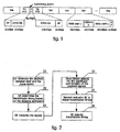
- the method of present embodiment comprises the following steps:
- the present embodiment uses the long-term filtering result of channel estimation to accurately obtain the path location, and at the same time it uses the instantaneous channel estimation result to obtain the channel estimation value of the related path, thereby improves the accuracy of channel estimation. But it can also use other channel estimation methods.
- Step 32 UE determines the transmission timing of the transmission signals for uplink synchronization time slot
- UE can estimate the distance to the base station and then computes the transmission timing; it also can be assumed that UE is at a certain location in the network, thereby using the set transmission timing. For example: assuming that UE is on the edge of the cell, the transmission timing can be set to be 96 chips prior to the receiving timing. Other methods can be used as well.
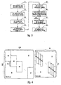
- Step 33 based on the downlink estimation result, UE constructs a 143*128-dimension transmission matrix A constructed with the convolution of spread spectrum sequence and channel estimation result. Meanwhile, it needs to construct a 1*143-dimension matrix d consisted of signals that will be transmitted and the elements "zero";
- Matrix A is constructed from eight parallel matrixes B, while matrix B is also constructed by sixteen parallel matrixes H T , wherein H T is the 16*1-dimension matrix represented by the channel estimation result.
- the construction method for matrix B is as follows: a new matrix of 31N*16 is constructed, wherein the first H T matrix is placed between the first column in the first row and the first column in the 16 th row within the newly constructed matrix, the next H T matrix is placed closely to the right of last H T matrix and the starting row is always added by one, and after arranging sixteen H T matrixes, other elements in the newly constructed matrix of 31N* 16 are filled with zeroes.
- the construction method for matrix A is as follows: a new matrix of 143N*128 is constructed, wherein the first B matrix is placed between first column in the first row and the 16th column in the 31 st row within the newly constructed matrix, the next B matrix is placed closely to the right of last B matrix and the starting row is always added by 16, and after arranging eight B matrixes, other elements in the newly constructed matrix of 143N*128 are filled with zeroes.
- the matrix [ S , 15 ⁇ 0 ⁇ ] T , namely fifteen zeroes are added after the uplink synchronous sequence that is originally intended to be transmitted to form a one-dimension matrix with 143 elements.
- UE can use MMSE-BLE, ZF-BLE methods and so on in the joint detection technology to solve the signal e .
- R e I
- a *T represents the transpose matrix of the conjugate matrix of A; ê c,MMSE-BLE represents the real transmission signal e ; R n is nominally named as noise space correlation matrix; R e is nominally named as signal space correlation matrix; R n -1 is the inverse matrix of R n ;
- the flow is exactly the same as the flow of the joint detection algorithm. It can also use Cholesky decomposition algorithm, approximate decomposition algorithm, as well as FFT, Schur algorithms, etc..
- Step 35 the UE utilizes the alternative signal e to replace the original uplink synchronous sequence for transmission, and its transmission timing can utilize the result from step 32;
- Step 36 the base station estimates the received signal by correlator, and sets the moment of the largest energy output as the timing for uplink signals, therefore deducts the time adjustments which is to be performed by UE to reach uplink synchronization;
- UE can also use the supplementary method of FFT. If it is discovered that in the searching window, there exists another peak value that is smaller than the largest peak value and the difference between them is smaller than x dB (x can be set between 0-20 dB). It can be believed that there are two users using the same access code to access, then the flow directly exits; otherwise, step 37 is executed.
- Step 37 based on the obtained information, the network instructs UE to finish the uplink signal transmission timing adjustment.
- this information is transmitted through the specific field in FPACH channel.
- Step 38 UE adjusts the transmission timing of the uplink signals based on the orders from network.
- the uplink signal can obtain the uplink synchronization at the side of base station.
- This communication process can further enter the tracking phase of uplink synchronization.
- the method of present invention eliminates the channel delay characteristics. Therefore it can more accurately compute the initial signal timing and obtain a more accurate time adjustment. What's more, it can precisely instruct UE to complete the establishment process of uplink synchronization.
- the present invention has fundamentally solved the problem of low probability of success in uplink synchronization establishment.
- the method used in the present invention is not limited in TD-SCDMA system.
- the method is respectively applied in TD-CDMA or WCDMA system, and uses the same flow in figure 3 , the only difference lies in the constructed matrix A and d , whose construction method is displayed in other patents and papers.
- the China Patent with the application number 03137628.2 and titled "A method of joint optimization for signals based on the joint detection and joint transmission technologies" discloses a construction method for matrix A and d in TD-SCDMA and WCDMA systems.
- the uplink access of TD-SCDMA system uses a special time slot structure and as a result, it proposes a generation method for the transmission matrix A of TD-SCDMA uplink accessing time slot in said embodiment of the present invention.
- the dimension of matrix A and B is determined by the width of the sequence that is intended to transmit and the window length of channel estimation. Besides, its dimension will change according to the value of the over sampling rate.
- the construction methods for matrix B and A are the same, but the dimension becomes larger; for example, the B matrix is of 31N*16, while A matrix is of 143N* 128, wherein N is an positive integer bigger than or equal to one.
- the dimension changes due to the over sampling rate can be considered as the same changes in the above example.
- the method in the present invention can be used in TD-SCDMA, TD-CDMA or WCDMA systems, and enable the base stations in such mobile communication systems to precisely instruct UE to finish the establishment process of uplink synchronization. It possesses the industry practicability.
Landscapes
- Engineering & Computer Science (AREA)
- Computer Networks & Wireless Communication (AREA)
- Signal Processing (AREA)
- Power Engineering (AREA)
- Physics & Mathematics (AREA)
- Mathematical Physics (AREA)
- Mobile Radio Communication Systems (AREA)
Claims (12)
- Herstellungsverfahren zur Uplink-Synchronisation auf der Basis einer Übertragungsgemeinschaftstechnologie, die in einem Mobilkommunikationssystem verwendet wird, und das die folgenden Schritte umfasst:(a) Ausführen einer Kanalschätzung für einen Downlink-Kanal nahe einem Uplink-Kanal durch eine Nutzerausrüstung, wobei die Kanalimpulsantwort des Uplink-Kanals und die Kanalimpulsantwort des Downlink-Kanals eine Korrelation innerhalb eines bestimmten Zeitbereichs aufweisen,(b) Bestimmen eines Sendezeitpunktes für Sendesignale eines Uplink-Synchronzeitschlitzes durch Nutzerausrüstung;(c) Erstellen einer Sendematrix A und einer Matrix d, die zu Signalen in Bezug steht, die ursprünglich dafür vorgesehen waren, durch Nutzerausrüstung auf der Basis eines Downlink-Kanalschätzungsergebnisses gesendet zu werden;(d) Lösen von d=Ae+n durch Nutzerausrüstung, Erhalten eines konvertierten Signals e, wobei n eine Rauschmatrix ist;(e) Verwenden des konvertierten Signals e zum Ersetzen einer ursprünglichen Uplink-Synchronsequenz zum Senden durch Nutzerausrüstung, und Verwenden des in Schritt (b) bestimmten Sendezeitpunktes beim Senden;(f) Schätzen empfangener Signale über einen Korrelator durch eine Basisstation, Erhalten eines Zeitablaufs von Uplink-Signalen, und Ableiten von Zeitjustierungen, die durch Nutzerausrüstung ausgeführt werden müssen, um eine Uplink-Synchronisation zu erreichen;(g) Instruieren von Nutzerausrüstung, Justierungen für den Sendezeitpunkt von Uplink-Signalen auf der Basis von erhaltenen Informationen durch das Netzwerk zu vollenden, und Justieren der Sendezeitpunkte von Uplink-Signalen durch Nutzerausrüstung, wodurch die Herstellung einer Uplink-Synchronisation erreicht wird.
- Verfahren nach Anspruch 1, wobei in dem Schritt (a) eine Nutzerausrüstung eine Kanalschätzung für einen Downlink-Pilotzeitschlitz oder einen primären gemeinsamen physischen Steuerungskanal ausführt.
- Verfahren nach Anspruch 1, wobei in dem Schritt (a), wenn eine Nutzerausrüstung eine Kanalschätzung ausführt, sie ein Langzeitfilterungsergebnis der Kanalschätzung verwendet, um die Position eines Pfades zu erhalten, und sie gleichzeitig ein Augenblicks-Kanalschätzungsergebnis verwendet, um einen Kanalschätzungswert eines zugehörigen Pfades zu erhalten.
- Verfahren nach Anspruch 1, wobei in dem Schritt (b) die Entfernung zu der Basisstation entsprechend der Stärke empfangener Signale geschätzt wird und dann der Sendezeitpunkt berechnet wird; oder es wird unter der Annahme, dass sich eine Nutzerausrüstung an einer bestimmten Position in einem Netz befindet, der Sendezeitpunkt auf der Basis eines Empfangszeitpunktes bestimmt wird.
- Verfahren nach Anspruch 1, wobei die Sendematrix A mit einer Faltung der Spreizspektrumsequenz und des Kanalschätzungsergebnisses erstellt wird, und die Matrix d durch Signale, die gesendet werden sollen, und Elemente "null" gebildet wird.
- Verfahren nach Anspruch 1 oder 5, wobei das Kommunikationssystem ein TD-SCDMA-System ist und das Kanalschätzungsergebnis in Schritt (a) als H = [h1, h2 ..., h16N] aufgezeichnet wird, wobei N eine Oversampling-Rate ist und eine ganze Zahl von mindestens 1 ist, und eine HT-Matrix als eine transponierte Matrix von H definiert wird, wobei dann in Schritt (c) die Sendematrix A durch folgende Schritte erstellt werden kann:(c1) zuerst Erstellen einer Matrix B gemäß folgendem Verfahren: eine neue Matrix aus 31 N × 16 wird erstellt, wobei eine erste HT-Matrix zwischen einer ersten Spalte in einer ersten Reihe und einer ersten Spalte in einer 16. Reihe innerhalb der neu erstellten Matrix angeordnet wird; als Nächstes wird eine HT-Matrix rechts nahe neben der zuletzt angeordneten HT-Matrix angeordnet, und eine Startreihe wird immer um eins hinzugefügt; nachdem sechzehn HT-Matrizes angeordnet wurden, werden andere Elemente in der neu erstellten Matrix aus 31 N × 16 mit Nullen gefüllt;(c2) dann Erstellen einer neuen Matrix aus 143Nx128, wobei eine erste B-Matrix zwischen einer ersten Spalte in einer ersten Reihe und einer 16. Spalte in einer 31. Reihe innerhalb der neu erstellten Matrix angeordnet wird; als Nächstes wird die B-Matrix rechts nahe neben der zuletzt angeordneten B-Matrix angeordnet, und eine Startreihe wird immer um 16 hinzugefügt; nachdem acht B-Matrizes angeordnet wurden, werden andere Elemente in der neu erstellten Matrix aus 143Nx128 mit Nullen gefüllt.
- Verfahren nach Anspruch 6, wobei in dem Schritt (c) die Matrix d eine eindimensionale Matrix ist, die 143N Elemente enthält und die erstellt wird, indem nach einer Uplink-Synchronsequenz, die ursprünglich gesendet werden sollte, mehrere Nullen hinzugefügt werden.
- Verfahren nach Anspruch 1, wobei die Rauschmatrix ein lokales Rauschen ist, das durch eine Nutzerausrüstung detektiert wird, oder sie wird durch Schätzen des SNR (Signal-Rausch-Verhältnisses) eines Uplink-Pilotzeitschlitzes auf der Basisstationsseite erhalten.
- Verfahren nach Anspruch 1, wobei in dem Schritt (d) ein Minimum Mean Square Error-Block Linear Equalizer (MMSE-BLE), sein vereinfachter Algorithmus oder ein Zero Forcing-Block Linear Equalizer (ZF-BLE) verwendet wird, um das Signal e zu lösen.
- Verfahren nach Anspruch 1, wobei in dem Schritt (f) ein Moment einer größten zugehörigen Energieabgabe als ein Zeitpunkt von Uplink-Signalen verwendet wird.
- Verfahren nach Anspruch 1, wobei in dem Schritt (f) die Basisstation auch bestimmt, ob es einen weiteren Spitzenwert innerhalb des Suchfensters gibt, der kleiner als ein größter Spitzenwert ist, und eine Differenz zwischen ihm und dem größten Spitzenwert kleiner als ein eingestellter Bereich ist, und wenn ja, so kann angenommen werden, dass zwei Nutzer denselben Zugangscode für den Zugang verwenden, woraufhin der Verfahrensablauf abbricht; anderenfalls wird Schritt (g) erneut ausgeführt.
- Verfahren nach Anspruch 1, wobei die Sendematrix A eine 143N×128-dimensionale Matrix ist, die acht Matrizes B enthält, eine erste B-Matrix zwischen einer ersten Spalte in einer ersten Reihe und einer 16. Spalte in einer 31. Reihe innerhalb der Sendematrix angeordnet wird; als Nächstes wird die B-Matrix rechts nahe neben der zuletzt angeordneten B-Matrix angeordnet, eine Startreihe wird immer um 16 hinzugefügt, und die anderen Elemente sind Nullen;
wobei die B-Matrix eine 31 N×16-dimensionale Matrix ist, die sechzehn HT-Matrizes enthält, wobei eine erste HT-Matrix zwischen einer ersten Spalte in einer ersten Reihe und einer ersten Spalte in einer 16. Reihe innerhalb der B-Matrix angeordnet wird; als Nächstes wird eine HT-Matrix rechts nahe neben der zuletzt angeordneten HT-Matrix angeordnet, und eine Startreihe wird immer um eins hinzugefügt; und die anderen Elemente sind Nullen;
wobei die Matrix HT eine transponierte Matrix von Matrix H ist, wobei die Matrix H eine eindimensionale Matrix ist, die durch das Kanalschätzungsergebnis, H = [h1, h2 ..., h16N], erstellt wird, wobei N eine Oversampling-Rate ist und eine ganze Zahl von mindestens eins ist.
Applications Claiming Priority (1)
| Application Number | Priority Date | Filing Date | Title |
|---|---|---|---|
| PCT/CN2005/000989 WO2007003071A1 (fr) | 2005-07-06 | 2005-07-06 | Procédé d’établissement de synchronisation de liaison ascendante reposant sur la technologie de transmission unifiée et matrice de transmission idoine |
Publications (3)
| Publication Number | Publication Date |
|---|---|
| EP1901465A1 EP1901465A1 (de) | 2008-03-19 |
| EP1901465A4 EP1901465A4 (de) | 2012-12-05 |
| EP1901465B1 true EP1901465B1 (de) | 2016-06-15 |
Family
ID=37604080
Family Applications (1)
| Application Number | Title | Priority Date | Filing Date |
|---|---|---|---|
| EP05772885.9A Expired - Lifetime EP1901465B1 (de) | 2005-07-06 | 2005-07-06 | Verfahren zur aufwärtsstrecken-synchronisationsherstellung auf der basis der vereinigten übertragungstechnologie und der übertragungsmatrix dafür |
Country Status (5)
| Country | Link |
|---|---|
| US (1) | US8300574B2 (de) |
| EP (1) | EP1901465B1 (de) |
| KR (1) | KR100925763B1 (de) |
| CN (1) | CN101133582B (de) |
| WO (1) | WO2007003071A1 (de) |
Families Citing this family (12)
| Publication number | Priority date | Publication date | Assignee | Title |
|---|---|---|---|---|
| CN1992556B (zh) * | 2005-12-27 | 2010-12-29 | 展讯通信(上海)有限公司 | 上行链路的同步方法及系统 |
| CN101420263A (zh) * | 2007-10-23 | 2009-04-29 | 中国移动通信集团公司 | 一种数据信息发送方法及其装置 |
| US8780790B2 (en) * | 2008-01-07 | 2014-07-15 | Qualcomm Incorporated | TDD operation in wireless communication systems |
| US8442566B2 (en) * | 2009-01-07 | 2013-05-14 | Samsung Electronics Co., Ltd. | Coordinated multipoint (CoMP) joint transmission using channel information feedback and higher rank dedicated beam-forming |
| CN101895308B (zh) * | 2009-05-22 | 2013-10-23 | 鼎桥通信技术有限公司 | 多覆盖区小区的上行信号检测方法和下行信号发送方法 |
| CN101938826B (zh) * | 2009-06-30 | 2013-06-12 | 中兴通讯股份有限公司 | 用于长期演进系统的上行同步控制方法和装置 |
| CN102448162B (zh) * | 2010-10-11 | 2014-07-16 | 中兴通讯股份有限公司 | 一种lte系统中上行发射定时控制方法与装置 |
| US20140078934A1 (en) * | 2011-05-10 | 2014-03-20 | Nokia Corporation | Delay feedback for coordinated multi-point transmission |
| US9609630B2 (en) * | 2014-02-21 | 2017-03-28 | Blackberry Limited | Uplink antenna selection device and method |
| CN106304313A (zh) * | 2015-05-21 | 2017-01-04 | 中兴通讯股份有限公司 | 定时偏移的处理方法及装置 |
| US10572770B2 (en) * | 2018-06-15 | 2020-02-25 | Intel Corporation | Tangent convolution for 3D data |
| US10915793B2 (en) * | 2018-11-08 | 2021-02-09 | Huawei Technologies Co., Ltd. | Method and system for converting point cloud data for use with 2D convolutional neural networks |
Family Cites Families (13)
| Publication number | Priority date | Publication date | Assignee | Title |
|---|---|---|---|---|
| CN1047047C (zh) | 1997-10-05 | 1999-12-01 | 北京信威通信技术有限公司 | 同步码分多址通信链路的建立和保持方法 |
| WO2003007520A1 (en) * | 2001-07-13 | 2003-01-23 | Linkair Communications, Inc. | A method and system for fast synchronization of uplink and a receiver for base station's access channel |
| US7224942B2 (en) | 2001-07-26 | 2007-05-29 | Telefonaktiebolaget Lm Ericsson (Publ) | Communications system employing non-polluting pilot codes |
| US6741653B2 (en) * | 2002-07-01 | 2004-05-25 | Interdigital Technology Corporation | Data detection for codes with non-uniform spreading factors |
| AU2003256426A1 (en) * | 2002-08-20 | 2004-03-11 | Interdigital Technology Corporation | Efficient joint detection |
| KR100557102B1 (ko) * | 2002-09-07 | 2006-03-03 | 삼성전자주식회사 | 이동통신 시스템에서 직교부호의 길이에 상관없는 공동검출 수신 장치 및 방법 |
| JPWO2004093476A1 (ja) * | 2003-04-16 | 2006-07-13 | 日本電気株式会社 | 移動通信システム、基地局、移動局、及びそれらに用いる無線通信方法 |
| CN1549612A (zh) * | 2003-05-19 | 2004-11-24 | 皇家飞利浦电子股份有限公司 | 无线通信网络中点到点对等通信的上行链路同步保持的方法和装置 |
| CN100420313C (zh) * | 2003-06-18 | 2008-09-17 | 北京邮电大学 | 基于联合检测联合发送技术的联合优化信号处理方法 |
| CN1622502A (zh) * | 2003-11-27 | 2005-06-01 | 皇家飞利浦电子股份有限公司 | 在tdd cdma通信体系中用于支持下行链路联合检测的方法和装置 |
| US20050175074A1 (en) * | 2004-02-11 | 2005-08-11 | Interdigital Technology Corporation | Wireless communication method and apparatus for performing multi-user detection using reduced length channel impulse responses |
| KR100918747B1 (ko) * | 2006-02-07 | 2009-09-24 | 삼성전자주식회사 | 직교 주파수 분할 다중 접속 방식을 사용하는 이동 통신시스템에서 상향링크 신호 송신 장치 및 방법 |
| KR100833064B1 (ko) | 2006-12-13 | 2008-05-27 | 에스케이 텔레콤주식회사 | Td-scdma 시스템의 동기 제어방법 및 이에 적용되는 장치 |
-
2005
- 2005-07-06 EP EP05772885.9A patent/EP1901465B1/de not_active Expired - Lifetime
- 2005-07-06 KR KR1020087001221A patent/KR100925763B1/ko not_active Expired - Fee Related
- 2005-07-06 CN CN2005800487577A patent/CN101133582B/zh not_active Expired - Fee Related
- 2005-07-06 WO PCT/CN2005/000989 patent/WO2007003071A1/zh not_active Ceased
- 2005-07-06 US US11/916,482 patent/US8300574B2/en not_active Expired - Fee Related
Also Published As
| Publication number | Publication date |
|---|---|
| EP1901465A1 (de) | 2008-03-19 |
| CN101133582B (zh) | 2011-02-02 |
| KR20080019712A (ko) | 2008-03-04 |
| WO2007003071A1 (fr) | 2007-01-11 |
| US8300574B2 (en) | 2012-10-30 |
| CN101133582A (zh) | 2008-02-27 |
| US20090303889A1 (en) | 2009-12-10 |
| EP1901465A4 (de) | 2012-12-05 |
| KR100925763B1 (ko) | 2009-11-11 |
Similar Documents
| Publication | Publication Date | Title |
|---|---|---|
| KR100557102B1 (ko) | 이동통신 시스템에서 직교부호의 길이에 상관없는 공동검출 수신 장치 및 방법 | |
| EP1158690B1 (de) | Pfadsucherkreislauf in welchem ein empfangenes Signal in eine Mehrzahl von FFT-Fenstern aufgeteilt wird | |
| EP1269646B1 (de) | Korrelationsfilter für den rückkanal in einem drahtlosen cdma system mit mehreren bit-raten | |
| US6370397B1 (en) | Search window delay tracking in code division multiple access communication systems | |
| CN101814931B (zh) | Td-scdma系统中多普勒频移估计和补偿的方法 | |
| EP1901465B1 (de) | Verfahren zur aufwärtsstrecken-synchronisationsherstellung auf der basis der vereinigten übertragungstechnologie und der übertragungsmatrix dafür | |
| JP2004525539A (ja) | 単一ユーザ検出 | |
| CN100508414C (zh) | Td-scdma系统中的下行同步校准方法和装置 | |
| KR20050005414A (ko) | 무선 수신기에서 채널 추정 | |
| CN1992556B (zh) | 上行链路的同步方法及系统 | |
| US7489732B2 (en) | Decreasing computational complexity of TD-SCDMA measurement process | |
| KR20050075553A (ko) | 다중반송파 코드분할다중접속 시스템에서의 역방향 파일럿설계 방법 | |
| KR100504360B1 (ko) | 수신기 및 수신 방법 | |
| US6925110B2 (en) | Signal processing method and device for a spread spectrum radio communication receiver | |
| EP1892869B1 (de) | Mehrcodesatz-kanalschätzungsverfahren in einem zeitschlitz-cdma-system | |
| US20050265496A1 (en) | Wireless system | |
| KR100605890B1 (ko) | 협대역 시분할 듀플렉싱 부호분할 다중 접속통신시스템에서 채널 추정 향상 장치 및 방법 | |
| CN101175296A (zh) | 一种上行多码集联合检测方法及系统 | |
| CN102111183B (zh) | 一种grake接收机及其合并权值计算方法 | |
| CN100388648C (zh) | 码分多址系统中用于降低接收干扰的装置 | |
| CN100388649C (zh) | 利用权值序列对信号序列进行加权处理的装置 | |
| CN100586035C (zh) | 用于降低码分多址系统中接收干扰的方法 | |
| CN2932835Y (zh) | 对加权相关结果进行归一化处理的装置 | |
| CN2932833Y (zh) | 对信号进行加权扩频的装置 | |
| CN2924933Y (zh) | 对信号进行加权扩频的装置 |
Legal Events
| Date | Code | Title | Description |
|---|---|---|---|
| PUAI | Public reference made under article 153(3) epc to a published international application that has entered the european phase |
Free format text: ORIGINAL CODE: 0009012 |
|
| 17P | Request for examination filed |
Effective date: 20080117 |
|
| AK | Designated contracting states |
Kind code of ref document: A1 Designated state(s): AT BE BG CH CY CZ DE DK EE ES FI FR GB GR HU IE IS IT LI LT LU LV MC NL PL PT RO SE SI SK TR |
|
| DAX | Request for extension of the european patent (deleted) | ||
| REG | Reference to a national code |
Ref country code: DE Ref legal event code: R079 Ref document number: 602005049531 Country of ref document: DE Free format text: PREVIOUS MAIN CLASS: H04J0013000000 Ipc: H04J0011000000 |
|
| A4 | Supplementary search report drawn up and despatched |
Effective date: 20121105 |
|
| RIC1 | Information provided on ipc code assigned before grant |
Ipc: H04L 25/02 20060101ALI20121029BHEP Ipc: H04J 11/00 20060101AFI20121029BHEP |
|
| GRAP | Despatch of communication of intention to grant a patent |
Free format text: ORIGINAL CODE: EPIDOSNIGR1 |
|
| INTG | Intention to grant announced |
Effective date: 20160108 |
|
| RIN1 | Information on inventor provided before grant (corrected) |
Inventor name: DING, MEILING |
|
| GRAS | Grant fee paid |
Free format text: ORIGINAL CODE: EPIDOSNIGR3 |
|
| GRAA | (expected) grant |
Free format text: ORIGINAL CODE: 0009210 |
|
| AK | Designated contracting states |
Kind code of ref document: B1 Designated state(s): AT BE BG CH CY CZ DE DK EE ES FI FR GB GR HU IE IS IT LI LT LU LV MC NL PL PT RO SE SI SK TR |
|
| REG | Reference to a national code |
Ref country code: CH Ref legal event code: EP Ref country code: GB Ref legal event code: FG4D |
|
| REG | Reference to a national code |
Ref country code: IE Ref legal event code: FG4D |
|
| REG | Reference to a national code |
Ref country code: AT Ref legal event code: REF Ref document number: 806983 Country of ref document: AT Kind code of ref document: T Effective date: 20160715 |
|
| REG | Reference to a national code |
Ref country code: FR Ref legal event code: PLFP Year of fee payment: 12 |
|
| REG | Reference to a national code |
Ref country code: DE Ref legal event code: R096 Ref document number: 602005049531 Country of ref document: DE |
|
| REG | Reference to a national code |
Ref country code: LT Ref legal event code: MG4D |
|
| REG | Reference to a national code |
Ref country code: NL Ref legal event code: MP Effective date: 20160615 |
|
| PG25 | Lapsed in a contracting state [announced via postgrant information from national office to epo] |
Ref country code: LT Free format text: LAPSE BECAUSE OF FAILURE TO SUBMIT A TRANSLATION OF THE DESCRIPTION OR TO PAY THE FEE WITHIN THE PRESCRIBED TIME-LIMIT Effective date: 20160615 Ref country code: FI Free format text: LAPSE BECAUSE OF FAILURE TO SUBMIT A TRANSLATION OF THE DESCRIPTION OR TO PAY THE FEE WITHIN THE PRESCRIBED TIME-LIMIT Effective date: 20160615 |
|
| REG | Reference to a national code |
Ref country code: AT Ref legal event code: MK05 Ref document number: 806983 Country of ref document: AT Kind code of ref document: T Effective date: 20160615 |
|
| PG25 | Lapsed in a contracting state [announced via postgrant information from national office to epo] |
Ref country code: GR Free format text: LAPSE BECAUSE OF FAILURE TO SUBMIT A TRANSLATION OF THE DESCRIPTION OR TO PAY THE FEE WITHIN THE PRESCRIBED TIME-LIMIT Effective date: 20160916 Ref country code: LV Free format text: LAPSE BECAUSE OF FAILURE TO SUBMIT A TRANSLATION OF THE DESCRIPTION OR TO PAY THE FEE WITHIN THE PRESCRIBED TIME-LIMIT Effective date: 20160615 Ref country code: NL Free format text: LAPSE BECAUSE OF FAILURE TO SUBMIT A TRANSLATION OF THE DESCRIPTION OR TO PAY THE FEE WITHIN THE PRESCRIBED TIME-LIMIT Effective date: 20160615 Ref country code: SE Free format text: LAPSE BECAUSE OF FAILURE TO SUBMIT A TRANSLATION OF THE DESCRIPTION OR TO PAY THE FEE WITHIN THE PRESCRIBED TIME-LIMIT Effective date: 20160615 |
|
| PG25 | Lapsed in a contracting state [announced via postgrant information from national office to epo] |
Ref country code: BE Free format text: LAPSE BECAUSE OF NON-PAYMENT OF DUE FEES Effective date: 20160731 |
|
| PG25 | Lapsed in a contracting state [announced via postgrant information from national office to epo] |
Ref country code: EE Free format text: LAPSE BECAUSE OF FAILURE TO SUBMIT A TRANSLATION OF THE DESCRIPTION OR TO PAY THE FEE WITHIN THE PRESCRIBED TIME-LIMIT Effective date: 20160615 Ref country code: CZ Free format text: LAPSE BECAUSE OF FAILURE TO SUBMIT A TRANSLATION OF THE DESCRIPTION OR TO PAY THE FEE WITHIN THE PRESCRIBED TIME-LIMIT Effective date: 20160615 Ref country code: RO Free format text: LAPSE BECAUSE OF FAILURE TO SUBMIT A TRANSLATION OF THE DESCRIPTION OR TO PAY THE FEE WITHIN THE PRESCRIBED TIME-LIMIT Effective date: 20160615 Ref country code: SK Free format text: LAPSE BECAUSE OF FAILURE TO SUBMIT A TRANSLATION OF THE DESCRIPTION OR TO PAY THE FEE WITHIN THE PRESCRIBED TIME-LIMIT Effective date: 20160615 Ref country code: IT Free format text: LAPSE BECAUSE OF FAILURE TO SUBMIT A TRANSLATION OF THE DESCRIPTION OR TO PAY THE FEE WITHIN THE PRESCRIBED TIME-LIMIT Effective date: 20160615 Ref country code: IS Free format text: LAPSE BECAUSE OF FAILURE TO SUBMIT A TRANSLATION OF THE DESCRIPTION OR TO PAY THE FEE WITHIN THE PRESCRIBED TIME-LIMIT Effective date: 20161015 |
|
| PG25 | Lapsed in a contracting state [announced via postgrant information from national office to epo] |
Ref country code: ES Free format text: LAPSE BECAUSE OF FAILURE TO SUBMIT A TRANSLATION OF THE DESCRIPTION OR TO PAY THE FEE WITHIN THE PRESCRIBED TIME-LIMIT Effective date: 20160615 Ref country code: PT Free format text: LAPSE BECAUSE OF FAILURE TO SUBMIT A TRANSLATION OF THE DESCRIPTION OR TO PAY THE FEE WITHIN THE PRESCRIBED TIME-LIMIT Effective date: 20161017 Ref country code: PL Free format text: LAPSE BECAUSE OF FAILURE TO SUBMIT A TRANSLATION OF THE DESCRIPTION OR TO PAY THE FEE WITHIN THE PRESCRIBED TIME-LIMIT Effective date: 20160615 Ref country code: AT Free format text: LAPSE BECAUSE OF FAILURE TO SUBMIT A TRANSLATION OF THE DESCRIPTION OR TO PAY THE FEE WITHIN THE PRESCRIBED TIME-LIMIT Effective date: 20160615 Ref country code: BE Free format text: LAPSE BECAUSE OF FAILURE TO SUBMIT A TRANSLATION OF THE DESCRIPTION OR TO PAY THE FEE WITHIN THE PRESCRIBED TIME-LIMIT Effective date: 20160615 |
|
| REG | Reference to a national code |
Ref country code: CH Ref legal event code: PL |
|
| REG | Reference to a national code |
Ref country code: DE Ref legal event code: R097 Ref document number: 602005049531 Country of ref document: DE |
|
| PG25 | Lapsed in a contracting state [announced via postgrant information from national office to epo] |
Ref country code: MC Free format text: LAPSE BECAUSE OF FAILURE TO SUBMIT A TRANSLATION OF THE DESCRIPTION OR TO PAY THE FEE WITHIN THE PRESCRIBED TIME-LIMIT Effective date: 20160615 |
|
| PLBE | No opposition filed within time limit |
Free format text: ORIGINAL CODE: 0009261 |
|
| STAA | Information on the status of an ep patent application or granted ep patent |
Free format text: STATUS: NO OPPOSITION FILED WITHIN TIME LIMIT |
|
| PG25 | Lapsed in a contracting state [announced via postgrant information from national office to epo] |
Ref country code: CH Free format text: LAPSE BECAUSE OF NON-PAYMENT OF DUE FEES Effective date: 20160731 Ref country code: LI Free format text: LAPSE BECAUSE OF NON-PAYMENT OF DUE FEES Effective date: 20160731 |
|
| REG | Reference to a national code |
Ref country code: IE Ref legal event code: MM4A |
|
| 26N | No opposition filed |
Effective date: 20170316 |
|
| PG25 | Lapsed in a contracting state [announced via postgrant information from national office to epo] |
Ref country code: DK Free format text: LAPSE BECAUSE OF FAILURE TO SUBMIT A TRANSLATION OF THE DESCRIPTION OR TO PAY THE FEE WITHIN THE PRESCRIBED TIME-LIMIT Effective date: 20160615 |
|
| REG | Reference to a national code |
Ref country code: FR Ref legal event code: PLFP Year of fee payment: 13 |
|
| PG25 | Lapsed in a contracting state [announced via postgrant information from national office to epo] |
Ref country code: IE Free format text: LAPSE BECAUSE OF NON-PAYMENT OF DUE FEES Effective date: 20160706 |
|
| PG25 | Lapsed in a contracting state [announced via postgrant information from national office to epo] |
Ref country code: LU Free format text: LAPSE BECAUSE OF NON-PAYMENT OF DUE FEES Effective date: 20160706 Ref country code: SI Free format text: LAPSE BECAUSE OF FAILURE TO SUBMIT A TRANSLATION OF THE DESCRIPTION OR TO PAY THE FEE WITHIN THE PRESCRIBED TIME-LIMIT Effective date: 20160615 |
|
| PG25 | Lapsed in a contracting state [announced via postgrant information from national office to epo] |
Ref country code: HU Free format text: LAPSE BECAUSE OF FAILURE TO SUBMIT A TRANSLATION OF THE DESCRIPTION OR TO PAY THE FEE WITHIN THE PRESCRIBED TIME-LIMIT; INVALID AB INITIO Effective date: 20050706 Ref country code: CY Free format text: LAPSE BECAUSE OF FAILURE TO SUBMIT A TRANSLATION OF THE DESCRIPTION OR TO PAY THE FEE WITHIN THE PRESCRIBED TIME-LIMIT Effective date: 20160615 |
|
| PG25 | Lapsed in a contracting state [announced via postgrant information from national office to epo] |
Ref country code: TR Free format text: LAPSE BECAUSE OF FAILURE TO SUBMIT A TRANSLATION OF THE DESCRIPTION OR TO PAY THE FEE WITHIN THE PRESCRIBED TIME-LIMIT Effective date: 20160615 |
|
| REG | Reference to a national code |
Ref country code: FR Ref legal event code: PLFP Year of fee payment: 14 |
|
| PG25 | Lapsed in a contracting state [announced via postgrant information from national office to epo] |
Ref country code: BG Free format text: LAPSE BECAUSE OF FAILURE TO SUBMIT A TRANSLATION OF THE DESCRIPTION OR TO PAY THE FEE WITHIN THE PRESCRIBED TIME-LIMIT Effective date: 20160615 |
|
| PGFP | Annual fee paid to national office [announced via postgrant information from national office to epo] |
Ref country code: FR Payment date: 20180711 Year of fee payment: 14 Ref country code: DE Payment date: 20180723 Year of fee payment: 14 |
|
| PGFP | Annual fee paid to national office [announced via postgrant information from national office to epo] |
Ref country code: GB Payment date: 20180718 Year of fee payment: 14 |
|
| REG | Reference to a national code |
Ref country code: DE Ref legal event code: R119 Ref document number: 602005049531 Country of ref document: DE |
|
| GBPC | Gb: european patent ceased through non-payment of renewal fee |
Effective date: 20190706 |
|
| PG25 | Lapsed in a contracting state [announced via postgrant information from national office to epo] |
Ref country code: DE Free format text: LAPSE BECAUSE OF NON-PAYMENT OF DUE FEES Effective date: 20200201 Ref country code: GB Free format text: LAPSE BECAUSE OF NON-PAYMENT OF DUE FEES Effective date: 20190706 |
|
| PG25 | Lapsed in a contracting state [announced via postgrant information from national office to epo] |
Ref country code: FR Free format text: LAPSE BECAUSE OF NON-PAYMENT OF DUE FEES Effective date: 20190731 |