EP1901447A1 - Wireless communication terminal apparatus and cqi selecting method - Google Patents
Wireless communication terminal apparatus and cqi selecting method Download PDFInfo
- Publication number
- EP1901447A1 EP1901447A1 EP06796493A EP06796493A EP1901447A1 EP 1901447 A1 EP1901447 A1 EP 1901447A1 EP 06796493 A EP06796493 A EP 06796493A EP 06796493 A EP06796493 A EP 06796493A EP 1901447 A1 EP1901447 A1 EP 1901447A1
- Authority
- EP
- European Patent Office
- Prior art keywords
- channel quality
- quality indicator
- cqi
- signal
- modulation
- Prior art date
- Legal status (The legal status is an assumption and is not a legal conclusion. Google has not performed a legal analysis and makes no representation as to the accuracy of the status listed.)
- Withdrawn
Links
Images


Classifications
-
- H—ELECTRICITY
- H04—ELECTRIC COMMUNICATION TECHNIQUE
- H04L—TRANSMISSION OF DIGITAL INFORMATION, e.g. TELEGRAPHIC COMMUNICATION
- H04L1/00—Arrangements for detecting or preventing errors in the information received
- H04L1/0001—Systems modifying transmission characteristics according to link quality, e.g. power backoff
- H04L1/0002—Systems modifying transmission characteristics according to link quality, e.g. power backoff by adapting the transmission rate
- H04L1/0003—Systems modifying transmission characteristics according to link quality, e.g. power backoff by adapting the transmission rate by switching between different modulation schemes
-
- H—ELECTRICITY
- H04—ELECTRIC COMMUNICATION TECHNIQUE
- H04W—WIRELESS COMMUNICATION NETWORKS
- H04W48/00—Access restriction; Network selection; Access point selection
- H04W48/08—Access restriction or access information delivery, e.g. discovery data delivery
-
- H—ELECTRICITY
- H04—ELECTRIC COMMUNICATION TECHNIQUE
- H04L—TRANSMISSION OF DIGITAL INFORMATION, e.g. TELEGRAPHIC COMMUNICATION
- H04L1/00—Arrangements for detecting or preventing errors in the information received
- H04L1/0001—Systems modifying transmission characteristics according to link quality, e.g. power backoff
- H04L1/0009—Systems modifying transmission characteristics according to link quality, e.g. power backoff by adapting the channel coding
-
- H—ELECTRICITY
- H04—ELECTRIC COMMUNICATION TECHNIQUE
- H04L—TRANSMISSION OF DIGITAL INFORMATION, e.g. TELEGRAPHIC COMMUNICATION
- H04L1/00—Arrangements for detecting or preventing errors in the information received
- H04L1/0001—Systems modifying transmission characteristics according to link quality, e.g. power backoff
- H04L1/0015—Systems modifying transmission characteristics according to link quality, e.g. power backoff characterised by the adaptation strategy
-
- H—ELECTRICITY
- H04—ELECTRIC COMMUNICATION TECHNIQUE
- H04L—TRANSMISSION OF DIGITAL INFORMATION, e.g. TELEGRAPHIC COMMUNICATION
- H04L1/00—Arrangements for detecting or preventing errors in the information received
- H04L1/0001—Systems modifying transmission characteristics according to link quality, e.g. power backoff
- H04L1/0023—Systems modifying transmission characteristics according to link quality, e.g. power backoff characterised by the signalling
- H04L1/0026—Transmission of channel quality indication
-
- H—ELECTRICITY
- H04—ELECTRIC COMMUNICATION TECHNIQUE
- H04L—TRANSMISSION OF DIGITAL INFORMATION, e.g. TELEGRAPHIC COMMUNICATION
- H04L5/00—Arrangements affording multiple use of the transmission path
- H04L5/003—Arrangements for allocating sub-channels of the transmission path
- H04L5/0044—Arrangements for allocating sub-channels of the transmission path allocation of payload
- H04L5/0046—Determination of how many bits are transmitted on different sub-channels
-
- H—ELECTRICITY
- H04—ELECTRIC COMMUNICATION TECHNIQUE
- H04L—TRANSMISSION OF DIGITAL INFORMATION, e.g. TELEGRAPHIC COMMUNICATION
- H04L5/00—Arrangements affording multiple use of the transmission path
- H04L5/003—Arrangements for allocating sub-channels of the transmission path
- H04L5/0058—Allocation criteria
- H04L5/006—Quality of the received signal, e.g. BER, SNR, water filling
-
- H—ELECTRICITY
- H04—ELECTRIC COMMUNICATION TECHNIQUE
- H04W—WIRELESS COMMUNICATION NETWORKS
- H04W88/00—Devices specially adapted for wireless communication networks, e.g. terminals, base stations or access point devices
- H04W88/02—Terminal devices
-
- H—ELECTRICITY
- H04—ELECTRIC COMMUNICATION TECHNIQUE
- H04W—WIRELESS COMMUNICATION NETWORKS
- H04W88/00—Devices specially adapted for wireless communication networks, e.g. terminals, base stations or access point devices
- H04W88/08—Access point devices
-
- H—ELECTRICITY
- H04—ELECTRIC COMMUNICATION TECHNIQUE
- H04L—TRANSMISSION OF DIGITAL INFORMATION, e.g. TELEGRAPHIC COMMUNICATION
- H04L27/00—Modulated-carrier systems
- H04L27/26—Systems using multi-frequency codes
- H04L27/2601—Multicarrier modulation systems
- H04L27/2626—Arrangements specific to the transmitter only
-
- H—ELECTRICITY
- H04—ELECTRIC COMMUNICATION TECHNIQUE
- H04L—TRANSMISSION OF DIGITAL INFORMATION, e.g. TELEGRAPHIC COMMUNICATION
- H04L27/00—Modulated-carrier systems
- H04L27/26—Systems using multi-frequency codes
- H04L27/2601—Multicarrier modulation systems
- H04L27/2647—Arrangements specific to the receiver only
Definitions
- the present invention relates to a radio communication terminal apparatus and a CQI (Channel Quality Indicator) selecting method.
- the AMC Adaptive Modulation and Coding
- the AMC Adaptive Modulation and Coding technique is adopted as a transmission scheme for high-speed packet transmission for changing a modulation scheme and coding rate adaptively in response to fluctuation of propagation environment.
- downlink quality is measured all the time in a communication terminal apparatus (hereinafter “UE” which means user equipment), and transmits measurement results (with downlink quality information) to a base station apparatus (hereinafter "Node B") in uplink.
- Node B selects a MCS (Modulation and Coding Scheme), which is a combination of a modulation scheme and a coding rate, based on downlink quality information and transmits downlink packets using the selected MCS.
- MCS Modulation and Coding Scheme
- Patent Document 1 discloses an improved AMC technique.
- Patent Document 1 discloses techniques of: dividing transmission schemes (i.e. modulation schemes) into a plurality of groups; deciding in which group a selected transmission scheme is included; transmitting group information when the group information is changed; and transmitting information that specifies the transmission scheme from the group at regular intervals.
- transmission schemes i.e. modulation schemes
- Patent Document 2 discloses another improved AMCtechnique.
- PatentDocument2 disclosesatechnique of reporting downlink quality information in a long period (long cycle) than the TTI (Transmission Time Interval), selecting a communication terminal preliminarily based on the report, and further reporting downlink quality information on the preliminarily-selected communication terminal in a short cycle.
- CQI is used for downlink quality information to be transmitted from UE to Node B.
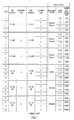
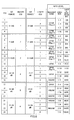
- FIG.1 illustrates a CQI table.
- the matching modulation scheme is QPSK (with a repetition factor of four), coding rate R is 7/16, and the number of information bits is 700.
- the number of information bits is the number of data bits not yet subj ected to coding to be actually transmitted.
- the CQI of level 1 and the CQI of level 2 have the same number of bits after coding, 800bits, buthavedifferent numbers of bits before coding, 100 bits and 200 bits, respectively. Further, in this case, the higher CQI is reported in a long cycle and the lower CQI is reported in a short cycle.
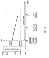
- FIG.2A illustrates changes of received SIR (Signal to Interference Ratio) in UE over time, where the vertical axis is SIR and the horizontal axis is time.
- SIR Signal to Interference Ratio
- the SIR is 5.5 dB and the CQI level is 6, so that the higher CQI of 2 and the lower CQI of 2 are reported.
- the SIR is 4.5 dB and the CQI level is 5, so that the lower CQI of 1 is reported.
- the SIR is 3 dB and the CQI level is 4, so that the higher CQI is 1 and the lower CQI is 4.
- time t2 is not in the higher CQI report cycle, and so the lower CQI level 4 alone is reported. Consequently, at Node B, the higher CQI is 2 and the lower CQI is 4, so that the CQI level is recognized to be 8, resulting in a wrong CQI recognition between UE and Node B, as shown in FIG.2B . That is, during a long cycle, even when there is SIR fluctuation over the higher CQI level, there is a problem that the higher CQI cannot be changed.
- the wireless communication terminal apparatus of the present invention employs a configuration having: a storage section that stores channel quality indicator information comprising higher channel quality indicators specifying channel quality indicator groups divided by levels and lower channel quality indicators specifying channel quality indicators in a group specified by a higher channel quality indicator and specifying part of channel quality indicators in an adj acent group of the group specified by the higher channel quality indicator; a channel quality indicator signal generating section that generates a higher channel quality indicator signal in a first cycle and a lower channel quality indicator signal in a second cycle shorter than the first cycle, according to the channel quality indicator information; and a transmitting section that transmits the generated higher channel quality indicator signal and lower channel quality indicator signal.
- the present invention enables accurate CQI selection by dividing CQI' s into groups by levels and reporting higher CQI's specifying groups in a long cycle and lower CQI's specifying CQI's in groups in a short cycle.
- FIG.3 is a block diagram showing the configuration of Node B 100 according to Embodiment 1 of the present invention.
- higher CQI signal decoding section 101 decodes the higher CQI signals of all subbands from signals transmitted by UE and received at the antenna, and outputs the decoded higher CQI's to subband scheduling section 102.
- Subband scheduling section 102 determines UE assigned per subband according to the higher CQI's of all subbands outputted from higher CQI signal decoding section 101, and outputs the determined UE' s and the subband numbers assigned to the UE' s (hereinafter collectively referred to as "scheduling information") to higher MCS determining section 104, higher MCS assignment signal generating section 108 and data signal generating section 110.
- CQI table storage section 103 CQI's are divided into groups by levels, and higher CQI's specifying groups and lower CQI's specifying CQI's included in the groups are associated with each other. Further, higher CQI's and lower CQI' s corresponds to higher MCS' s and lower MCS' s, respectively. Further, the SIR of a lower CQI is set to overlap with the SIR of the higher CQI of adj acent levels of the higher CQI associated with that lower CQI. By the way, the CQI table will be described later in detail.
- Higher MCS determining section 104 recognizes the UE to be assigned to a subband from scheduling information outputted from subband scheduling section 102, detects the higher MCS associated with the higher CQI of this UE from CQI table storage section 103, and determines assigning the detected higherMCS to the UE.
- HigherMCS determining section 104 outputs the determined higher MCS to MCS determining section 107 and higher MCS assignment signal generating section 108.
- Lower CQI signal decoding section 105 decodes the lower CQI signals from signals transmitted by the UE and received at the antenna, and outputs the decoded lower CQI's to lower MCS determining section 106.
- LowerMCS determining section 106 detects fromCQI table storage section 103 the lower MCS associated with the lower CQI outputted from lower CQI signal decoding section 105, and determines to assign the detected lower MCS to the UE. Further, lower MCS determining section 106 outputs the determined lower MCS to MCS determining section 107 and lower MCS assignment signal generating section 109.
- MCS determining section 107 determines the MCS using the higher MCS outputted from higher MCS determining section 104 and the lower MCS outputted from lower MCS determining section 106, and outputs the determined MCS to data signal generating section 110.
- Higher MCS assignment signal generating section 108 generates a higher MCS assignment signal including the ID of UE assigned subbands, the subband number and the higher MCS assigned to the UE, according to the scheduling information outputted from subband scheduling section 102 and the higher MCS outputted from higher MCS determining section 104, and outputs the generated higher MCS assignment signal to multiplexing section 112.
- Lower MCS assignment signal generating section 109 generates a lower MCS assignment signal according to the MCS outputted from lower MCS determining section 106 and outputs the generated lower MCS assignment signal to multiplexing section 112.
- Data signal generating section 110 performs modulation and coding on data to be transmitted to the UE assigned subbands using the MCS outputted from MCS determining section 107, according to the scheduling information outputted from subband scheduling section 102, and outputs data signals subjected to modulation and coding to multiplexing section 112.
- Pilot signal generating section 111 generates a pilot signal and outputs the generated signal to multiplexing section 112.
- Multiplexing section 112 multiplexes the higher MCS assignment signal, the lower MCS assignment signal, the data signal and the pilot signal, and outputs the multiplex signal to IFFT section 113, and IFFT section 113 converts the frequency domain signal into a time domain signal by performing an IFFT (Inverse Fast Fourier Transform) on the multiplex signal. That is, multiplexing section 112 frequency-multiplexes the multiplex signal over a plurality of orthogonal subbands, and the multiplex signal subjected to frequency multiplexing is outputted to GI inserting section 114.
- IFFT Inverse Fast Fourier Transform
- GI inserting section 114 inserts a GI (Guard Interval) into the signal outputted from IFFT section 113 and transmits the signal subjected to GI insertion to the UE via the antenna.
- GI Guard Interval
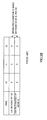
- the CQI table provided in CQI table storage section 103 will be described below using FIG.4 .
- FIG.4 there are 24 levels of CQI's and these 24 levels are divided into six groups per four levels each. These groups are specified by six higher CQI levels and the four levels in each group are specified by four lower CQI levels.
- the higher CQI level 1 is associated with received SIR 0 to 4 dB in the UE
- the higher CQI level 2 is associated with received SIR 4 to 8 dB.
- received SIR is associated with higher CQI's per 4 dB up to 24 dB
- SIR -1 to 5 dB is associated with the lower CQI level 1 to 4 associated with the higher CQI level 1
- SIR 2 to 9 dB is associated with the lower CQI level 1 to 4 associated with the higher CQI level 2
- the SIR of the lower CQI is set to overlap with the SIR of the higher CQI of adjacent levels of the higher CQI associated with that lower CQI.
- higher CQI's correspond to modulation schemes as higher MCS's
- lower CQI's correspond to coding rates and the numbers of information bits as lower MCS.
- the higher CQI level 1 corresponds to the higher MCS level 1 (QPSK, with a repetition factor of eight)
- the lower CQI level 1 corresponds to the lower MCS level 1 and the coding rate R of 1/4.
- the number of information bits is determined by the higher MCS and the lower MCS.
- FIG.5 is a block diagram showing the configuration of UE 200 according to Embodiment 1 of the present invention.
- GI removing section 201 removes a GI from the signal received in antenna and outputs the signal subjected to GI removal to FFT section 202.
- FFT section 202 converts the time domain signal into a frequency domain signal by performing an FFT (Fast Fourier Transform) on the signal outputted from GI removing section 201 and outputs the signal subjected to FFT to demultiplexing section 203.
- FFT Fast Fourier Transform
- Demultiplexing section 203 demultiplexes the signal outputted from FFT section 202 into the higher MCS assignment signal, the lower MCS assignment signal, the data signal and the pilot signal, and outputs the higher MCS assignment signal to higher MCS assignment signal decoding section 204, the lower MCS assignment signal to lower MCS assignment signal decoding section 205, the data signal to data signal decoding section 206 and the pilot signal to pilot signal decoding section 207.
- Higher MCS assignment signal decoding section 204 decodes the higher MCS assignment signal outputted from demultiplexing section 203 and decides whether or not Node B assigns the UE to subbands according to the result of decoding. The result of decision is outputted to lower MCS assignment signal decoding section 205.
- lower MCS assignment signal decoding section 205 decodes the lower MCS assignment signal outputted from demultiplexing section 203.
- the decoded lower MCS assignment signal is outputted to data signal decoding section 206.
- Data signal decoding section 206 decodes the data signal outputted fromdemultiplexing section 203 according to the lower MCS assignment signal outputted from lowerMCS assignment signal decoding section 205.
- Pilot signal decoding section 207 decodes the pilot signal outputted from demultiplexing section 203, outputs, when the decision result from higher MCS assignment signal decoding section 204 shows that subbands are assigned to the UE, the decoded signal to higher CQI signal generating section 209 and lower CQI signal generating section 210, and outputs, when the decision result from higher MCS assignment signal decoding section 204 shows that subbands are not assigned to the UE, the decoded signal to higher CQI signal generating section 209 alone.
- CQI table storage section 208 stores the same CQI table as stored in CQI table storage section 103 of Node B 100.
- Higher CQI signal generating section 209 measures the received SIR according to the pilot signal outputted from pilot signal decoding section 207, detects the higher CQI associated with the received SIR from CQI table 208, generates a higher CQI signal and transmits the generated higher CQI signal to Node B 100.
- Lower CQI signal generating section 210 measures the received SIR according to the pilot signal outputted from pilot signal decoding section 207, detects the lower CQI associated with the received SIR from CQI table storage section 208, generates a lower CQI signal and outputs the generated lower CQI signal to Node B 100.
- step (hereinafter abbreviated to "ST") 401 of FIG. 6 UE 200 transmits higher CQI signals associated with received SIRs of all subbands to Node B 100, and, in ST402, Node B 100 determines subbands and the higher MCS to be assigned to UE 200 according to the higher CQI signals.
- Node B 100 transmits the higherMCS assignment signal to UE 200, and, in ST404, UE 200 transmits to Node B 100 the lower CQI signal associated with only subbands assigned by the higher MCS assignment signal.
- Node B 100 determines transmission data and its coding rate according to the higher MCS determined in ST402 and the lower CQI transmitted in ST404, and, in ST406, transmits the lower MCS assignment signal to UE 200.
- ST407 Node B 100 transmits data to UE 200
- the processing in ST408 is the same as in ST404, and, after ST408, ST404 to ST407 are repeated three times in a cycle of 2.5 msecs.
- ST409 is the same as ST401 and is performed 10 msecs after the processing of ST401 is performed.
- FIG. 7A illustrates changes of received SIR in UE 200 over time, where the vertical axis is SIR and the horizontal axis is time.
- the SIR is 3 dB and the CQI level is 5, so that the higher CQI is 2 and the lower CQI is 1.
- the SIR associated with a lower CQI is set to overlap with the SIR of adjacent levels of the higher CQI associated with that lower CQI, so that it is possible to respond to fluctuation of SIR over the higher CQI level, even when the higher CQI cannot be changed during a long cycle, by changing the lower CQI, consequently enabling accurate CQI selection and synchronized CQI recognition between UE and Node B.
- Node B according to Embodiment 2 of the present invention is the same as in FIG.3 and the configuration of UE according to Embodiment 2 of the present invention is the same as in FIG.5 , and, consequently, detailed explanations thereof will be omitted.
- the CQI table provided in CQI table storage sections 103 and 208 is different from FIG. 4 , and, consequently, this CQI table will be explained using FIGs.8 and 9 .
- the CQI table shown in FIG.8 is made using the CQI table shown in FIG.1 , as shown in FIG.9 .
- the MCS level associated with the higher CQI level 2 and the lower CQI level 1 is changed such that the MCS level corresponds to the higher CQI level 1 and the lower CQI level 4
- the MCS level associated with the higher CQI level 2 and the lower CQI level 3 is changed such that the MCS level corresponds to the higher CQI level 3 and the lower CQI level 1.
- the above-described change is made for each higher CQI level.
- Embodiment 2 by making the step width of the number of information bits smaller in the CQI table, it is possible to select CQI accurately.
- each function block employed in the description of each of the aforementioned embodiments may typically be implemented as an LSI constituted by an integrated circuit. These may be individual chips or partially or totally contained on a single chip. "LSI” is adopted here but this may also be referred to as “IC,” “system LSI,” “super LSI,” or “ultra LSI” depending on differing extents of integration.
- circuit integration is not limited to LSI's, and implementation using dedicated circuitry or general purpose processors is also possible.
- FPGA Field Programmable Gate Array
- reconfigurable processor where connections and settings of circuit cells in an LSI can be reconfigured is also possible.
- the radio communication terminal apparatus and the CQI selecting method of the present invention provide an advantage of enabling accurate CQI selection and are applicable to, for example, communication terminal apparatus in OFDM radio communication systems.
Landscapes
- Engineering & Computer Science (AREA)
- Signal Processing (AREA)
- Computer Networks & Wireless Communication (AREA)
- Quality & Reliability (AREA)
- Computer Security & Cryptography (AREA)
- Mobile Radio Communication Systems (AREA)
Applications Claiming Priority (2)
| Application Number | Priority Date | Filing Date | Title |
|---|---|---|---|
| JP2005238020 | 2005-08-18 | ||
| PCT/JP2006/316136 WO2007020958A1 (ja) | 2005-08-18 | 2006-08-17 | 無線通信端末装置及びcqi選択方法 |
Publications (1)
| Publication Number | Publication Date |
|---|---|
| EP1901447A1 true EP1901447A1 (en) | 2008-03-19 |
Family
ID=37757615
Family Applications (1)
| Application Number | Title | Priority Date | Filing Date |
|---|---|---|---|
| EP06796493A Withdrawn EP1901447A1 (en) | 2005-08-18 | 2006-08-17 | Wireless communication terminal apparatus and cqi selecting method |
Country Status (9)
| Country | Link |
|---|---|
| US (1) | US7853217B2 (ru) |
| EP (1) | EP1901447A1 (ru) |
| JP (1) | JP4818271B2 (ru) |
| KR (1) | KR20080045134A (ru) |
| CN (1) | CN101243624A (ru) |
| BR (1) | BRPI0614986A2 (ru) |
| CA (1) | CA2617727A1 (ru) |
| RU (1) | RU2008105885A (ru) |
| WO (1) | WO2007020958A1 (ru) |
Cited By (1)
| Publication number | Priority date | Publication date | Assignee | Title |
|---|---|---|---|---|
| US7864698B2 (en) | 2006-06-26 | 2011-01-04 | Panasonic Corporation | Radio communication device and CQI generation method |
Families Citing this family (16)
| Publication number | Priority date | Publication date | Assignee | Title |
|---|---|---|---|---|
| US7830977B2 (en) * | 2006-05-01 | 2010-11-09 | Intel Corporation | Providing CQI feedback with common code rate to a transmitter station |
| KR20080041096A (ko) * | 2007-03-13 | 2008-05-09 | 엘지전자 주식회사 | 무선 통신 시스템에서 피드백 정보를 이용한 링크 적응방법 |
| US8417255B2 (en) | 2007-03-16 | 2013-04-09 | Qualcomm Incorporated | Data transmission and power control in a multihop relay communication system |
| KR101329872B1 (ko) * | 2007-06-08 | 2013-11-15 | 샤프 가부시키가이샤 | 이동 통신 시스템, 기지국 장치, 이동국 장치 및 통신 방법 |
| US9668265B2 (en) | 2008-03-28 | 2017-05-30 | Qualcomm Inc. | Technique for mitigating interference in a celllar wireless communication netwok |
| CN101572585B (zh) * | 2008-04-29 | 2013-01-02 | 华为技术有限公司 | 数据mcs与cqi码率间映射关系的获取方法和装置 |
| US8761824B2 (en) | 2008-06-27 | 2014-06-24 | Qualcomm Incorporated | Multi-carrier operation in a wireless communication network |
| JP2010016674A (ja) * | 2008-07-04 | 2010-01-21 | Fujitsu Ltd | 無線通信装置、無線通信システム、及び無線通信方法 |
| US20110122811A1 (en) * | 2008-07-07 | 2011-05-26 | Nortel Networks Limited | Codebook restructure, differential encoding/decoding and scheduling |
| US20110122963A1 (en) * | 2008-07-07 | 2011-05-26 | Jun Yuan | Codebook restructure, differential encoding/decoding, and scheduling |
| KR101003588B1 (ko) * | 2008-10-31 | 2010-12-22 | 삼성전기주식회사 | 무선 통신용 간섭 검출 장치 및 간섭 검출 방법 |
| EP2282418A3 (en) * | 2009-06-23 | 2011-03-09 | Alcatel Lucent | A station comprising at least two transmit antennas, and a method of transmitting therefrom |
| WO2012030271A1 (en) * | 2010-09-03 | 2012-03-08 | Telefonaktiebolaget L M Ericsson (Publ) | Scheduling multiple users on a shared communication channel in a wireless communication system |
| US20140086190A1 (en) * | 2011-05-10 | 2014-03-27 | Ntt Docomo, Inc. | Mobile station device, communication method, and computer program |
| JP5874002B2 (ja) * | 2011-11-10 | 2016-03-01 | パナソニックIpマネジメント株式会社 | 送信装置及び送信方法 |
| CN112929980A (zh) | 2019-12-06 | 2021-06-08 | 中兴通讯股份有限公司 | 初始mcs值确定方法、电子设备及存储介质 |
Family Cites Families (19)
| Publication number | Priority date | Publication date | Assignee | Title |
|---|---|---|---|---|
| JP3904807B2 (ja) | 1999-06-04 | 2007-04-11 | 株式会社半導体エネルギー研究所 | 表示装置 |
| JP3589992B2 (ja) | 2001-02-27 | 2004-11-17 | 松下電器産業株式会社 | 通信装置及び伝送方式選択方法 |
| JP3984799B2 (ja) | 2001-04-19 | 2007-10-03 | 松下電器産業株式会社 | 無線送信装置及び無線通信方法 |
| KR100493079B1 (ko) * | 2001-11-02 | 2005-06-02 | 삼성전자주식회사 | 고속 순방향 패킷 접속 방식을 사용하는 광대역 부호 분할다중 접속 통신 시스템에서 순방향 채널 품질을 보고하는장치 및 방법 |
| KR100879942B1 (ko) * | 2002-02-16 | 2009-01-22 | 엘지전자 주식회사 | 채널품질지시자 코딩을 위한 기저수열 생성방법 |
| US7103325B1 (en) * | 2002-04-05 | 2006-09-05 | Nortel Networks Limited | Adaptive modulation and coding |
| DK1568185T3 (da) * | 2002-12-04 | 2011-07-11 | Interdigital Tech Corp | Pålidelighedsdetektering af kanalkvalitetsindikator (CQI) og anvendelse af effektstyring i ydre sløjfe |
| EP1593222A1 (de) * | 2003-02-14 | 2005-11-09 | Siemens Aktiengesellschaft | Verfahren zur datenübertragung |
| JP2004312458A (ja) * | 2003-04-08 | 2004-11-04 | Matsushita Electric Ind Co Ltd | 基地局装置および適応変調方法 |
| US7013143B2 (en) * | 2003-04-30 | 2006-03-14 | Motorola, Inc. | HARQ ACK/NAK coding for a communication device during soft handoff |
| KR100640461B1 (ko) * | 2003-07-30 | 2006-10-30 | 삼성전자주식회사 | 직교 주파수 분할 다중 접속 방식을 사용하는 이동 통신시스템에서 서브 채널 할당 장치 및 방법 |
| GB2404539B (en) * | 2003-07-31 | 2006-06-14 | Fujitsu Ltd | Adaptive modulation and coding |
| JP4211032B2 (ja) * | 2003-08-15 | 2009-01-21 | 富士通株式会社 | 通信品質制御機能を有する通信装置 |
| JP4215601B2 (ja) | 2003-09-05 | 2009-01-28 | 富士通株式会社 | 無線通信装置 |
| JP2005136773A (ja) | 2003-10-31 | 2005-05-26 | Sony Ericsson Mobilecommunications Japan Inc | 無線伝送システム、送信側装置および受信側装置 |
| JP2005238020A (ja) | 2004-02-24 | 2005-09-08 | Touzai Kagaku Sangyo Kk | 薬液注入装置 |
| JP4506360B2 (ja) * | 2004-08-16 | 2010-07-21 | 富士通株式会社 | 移動局 |
| JP2006174279A (ja) * | 2004-12-17 | 2006-06-29 | Fujitsu Ltd | 無線基地局、移動局 |
| US7764743B2 (en) * | 2005-08-05 | 2010-07-27 | Alcatel-Lucent Usa Inc. | Methods of channel coding for communication systems |
-
2006
- 2006-08-17 EP EP06796493A patent/EP1901447A1/en not_active Withdrawn
- 2006-08-17 BR BRPI0614986-3A patent/BRPI0614986A2/pt not_active Application Discontinuation
- 2006-08-17 JP JP2007531014A patent/JP4818271B2/ja not_active Expired - Fee Related
- 2006-08-17 RU RU2008105885/09A patent/RU2008105885A/ru not_active Application Discontinuation
- 2006-08-17 KR KR1020087003675A patent/KR20080045134A/ko active IP Right Grant
- 2006-08-17 US US12/063,841 patent/US7853217B2/en active Active
- 2006-08-17 CN CNA2006800296589A patent/CN101243624A/zh not_active Withdrawn
- 2006-08-17 CA CA002617727A patent/CA2617727A1/en not_active Withdrawn
- 2006-08-17 WO PCT/JP2006/316136 patent/WO2007020958A1/ja active Application Filing
Non-Patent Citations (1)
| Title |
|---|
| See references of WO2007020958A1 * |
Cited By (1)
| Publication number | Priority date | Publication date | Assignee | Title |
|---|---|---|---|---|
| US7864698B2 (en) | 2006-06-26 | 2011-01-04 | Panasonic Corporation | Radio communication device and CQI generation method |
Also Published As
| Publication number | Publication date |
|---|---|
| US7853217B2 (en) | 2010-12-14 |
| JP4818271B2 (ja) | 2011-11-16 |
| JPWO2007020958A1 (ja) | 2009-03-26 |
| WO2007020958A1 (ja) | 2007-02-22 |
| BRPI0614986A2 (pt) | 2011-04-26 |
| RU2008105885A (ru) | 2009-08-20 |
| CA2617727A1 (en) | 2007-02-22 |
| KR20080045134A (ko) | 2008-05-22 |
| CN101243624A (zh) | 2008-08-13 |
| US20090111384A1 (en) | 2009-04-30 |
Similar Documents
| Publication | Publication Date | Title |
|---|---|---|
| EP1901447A1 (en) | Wireless communication terminal apparatus and cqi selecting method | |
| US11825477B2 (en) | System and method for performing resource allocation in radio communication | |
| KR101239600B1 (ko) | 이동국 장치, 기지국 장치 및 cqi 보고 방법 | |
| US7733977B2 (en) | Radio transmission device and radio transmission method | |
| KR20100138261A (ko) | 무선통신 시스템에서 참조신호의 할당방법 및 그 장치, 그 장치를 이용한 송수신장치 | |
| KR20110122959A (ko) | 광대역 무선통신 시스템에서 사운딩 신호 송수신을 위한 장치 및 방법 |
Legal Events
| Date | Code | Title | Description |
|---|---|---|---|
| PUAI | Public reference made under article 153(3) epc to a published international application that has entered the european phase |
Free format text: ORIGINAL CODE: 0009012 |
|
| 17P | Request for examination filed |
Effective date: 20080131 |
|
| AK | Designated contracting states |
Kind code of ref document: A1 Designated state(s): AT BE BG CH CY CZ DE DK EE ES FI FR GB GR HU IE IS IT LI LT LU LV MC NL PL PT RO SE SI SK TR |
|
| DAX | Request for extension of the european patent (deleted) | ||
| RAP1 | Party data changed (applicant data changed or rights of an application transferred) |
Owner name: PANASONIC CORPORATION |
|
| STAA | Information on the status of an ep patent application or granted ep patent |
Free format text: STATUS: THE APPLICATION HAS BEEN WITHDRAWN |
|
| 18W | Application withdrawn |
Effective date: 20120618 |
|
| DAX | Request for extension of the european patent (deleted) |