EP1901226A2 - Hierarchische Miniatur-Sicherheitsmarkierungen - Google Patents
Hierarchische Miniatur-Sicherheitsmarkierungen Download PDFInfo
- Publication number
- EP1901226A2 EP1901226A2 EP07110368A EP07110368A EP1901226A2 EP 1901226 A2 EP1901226 A2 EP 1901226A2 EP 07110368 A EP07110368 A EP 07110368A EP 07110368 A EP07110368 A EP 07110368A EP 1901226 A2 EP1901226 A2 EP 1901226A2
- Authority
- EP
- European Patent Office
- Prior art keywords
- marks
- security mark
- security
- groups
- rules
- Prior art date
- Legal status (The legal status is an assumption and is not a legal conclusion. Google has not performed a legal analysis and makes no representation as to the accuracy of the status listed.)
- Ceased
Links
Images


Classifications
-
- G—PHYSICS
- G06—COMPUTING OR CALCULATING; COUNTING
- G06K—GRAPHICAL DATA READING; PRESENTATION OF DATA; RECORD CARRIERS; HANDLING RECORD CARRIERS
- G06K19/00—Record carriers for use with machines and with at least a part designed to carry digital markings
-
- H—ELECTRICITY
- H04—ELECTRIC COMMUNICATION TECHNIQUE
- H04N—PICTORIAL COMMUNICATION, e.g. TELEVISION
- H04N1/00—Scanning, transmission or reproduction of documents or the like, e.g. facsimile transmission; Details thereof
- H04N1/32—Circuits or arrangements for control or supervision between transmitter and receiver or between image input and image output device, e.g. between a still-image camera and its memory or between a still-image camera and a printer device
- H04N1/32101—Display, printing, storage or transmission of additional information, e.g. ID code, date and time or title
- H04N1/32144—Display, printing, storage or transmission of additional information, e.g. ID code, date and time or title embedded in the image data, i.e. enclosed or integrated in the image, e.g. watermark, super-imposed logo or stamp
-
- G—PHYSICS
- G06—COMPUTING OR CALCULATING; COUNTING
- G06F—ELECTRIC DIGITAL DATA PROCESSING
- G06F15/00—Digital computers in general; Data processing equipment in general
Definitions
- the exemplary embodiment relates to the digital imaging arts. It finds particular application in conjunction with a method and apparatus for utilizing miniature security marks for watermarking documents and may be used to distinguish authentic documents from counterfeit documents.
- Machine readable information in the form of watermarks, barcodes, and the like has been embedded into images on paper for a variety of applications, such as document identification and authenticity verification.
- the code is generally invisible or visually unobstructive and may be decoded by a device which is capable of reading the information.
- Current counterfeit prevention systems are frequently based on the use of digital watermarks.
- Digital watermarking is a technique which allows a user to add information (e.g., copyright notices, security codes, identification data, etc.) to digital image signals and documents. Such data can be in a group of bits describing information pertaining to the signal or to the author of the signal (e.g., name, place, etc.).
- Most common watermarking methods for images work in spatial or frequency domains.
- the simplest method involves flipping the lowest-order bit of chosen pixels in a gray scale or color image. This tends to work well only if the image will not be subject to any human or noisy modification.
- a more robust watermark can be embedded in an image in the same way that a watermark is added to paper. Such techniques may superimpose a watermark symbol over an area of the picture and then add some fixed intensity value for the watermark to the varied pixel values of the image. The resulting watermark may be visible or invisible depending upon the value (large or small, respectively) of the watermark intensity.
- Spatial watermarking can also be applied using color separation. In this way, the watermark appears in only one of the color separations. This renders the watermark visibly subtle such that it is difficult to detect under regular viewing.
- extraction hardware and/or software is generally employed. As the digital watermarks usually have fairly large footprints, detectors employed to read the digital watermarks often require significant buffering storage. Consequently, this increases the detection costs, particularly if the watermark extraction is implemented in hardware.
- U.S. Patent No. 7,002,704 discloses a system for rendering an electronic image representation associated with a software application program.
- the system includes a host processor programmed to execute the software application program, a temporary storage device associated with the host processor, a printer interfaced to the host processor, and a software program operative on the host processor for determining whether the electronic image representation is of a predetermined document type by examining at least a portion of the electronic image representation when stored in the temporary storage device during the course of printing the electronic image representation at the printer.
- U.S. Patent No. 6,694,042 discloses printing documents and other objects with machine readable indicia, such as steganographic digital watermarks or barcodes, for enabling document management functions.
- the indicia can be added as part of the printing process, such as by printer driver software, by a Postscript engine in a printer.
- the indicia can encode data about the document, or can encode an identifier that references a database record containing such data.
- a suitable optical input device e.g., a webcam
- U.S. Application Serial No. 11/317,768 discloses a system which applies a security mark to a recipient, such as an image or document.
- a data reception component receives information from one or more sources.
- a security mark generation component generates at least one miniature security mark (MSM) configuration based at least in part upon the information from the data reception component.
- An application component applies the at least one MSM configuration to one or more recipients.
- MSM miniature security mark
- a system for generating a security mark includes a data reception component that receives information.
- a security mark generation component in communication with the data reception component, generates at least one security mark configuration based at least in part upon the received information.
- the at least one security mark configuration includes a plurality of marks.
- An application component applies one configuration of the at least one security mark configurations to a recipient, the applied security mark configuration obeying a predetermined set of rules which include at least one rule which defines a spatial relationship between a first group of the plurality of marks and a second group of the plurality of marks.
- the applied security mark configuration comprises a first group of the plurality of marks and at least a second group of the plurality of marks.
- each of the first and at least second groups of marks comprises at least three marks.
- each of the at least three marks in the first and at least second groups of marks is identical in at least one of size, shape, and color to the others of the at least three marks.
- the first group of marks and the at least second group of marks obey a first set of rules which define inter-group spatial relationships between groups of marks, the first group of marks obeying a second set of rules which defines intra-group spatial relationships between marks in a group, the at least second group of marks obeying the second set of rules.
- the at least second group of the plurality of marks comprises at least two second groups of marks.
- the first set of rules define a permitted spacing between groups of marks as a function of a fixed spacing. In a further embodiment the first set of rules define a permitted spacing between groups of marks as a function of a fixed spacing in two mutually perpendicular directions.
- the application component applies the security mark with at least one of printing, engraving, embossing, discoloration and material removal of the recipient.
- the information received is representative of at least one of an origin of manufacture, a date, a time, a serial number, and an alphanumeric string.
- a method for applying a security mark to a recipient includes generating at least one security mark configuration representative of information to be applied to a recipient.
- the at least one security mark configuration includes a plurality of marks which obey rules which provide a limited flexibility in the positioning of groups of the marks.
- One configuration of the at least one security mark configurations is applied to a recipient.
- the applied security mark configuration obeys a predetermined set of rules which include at least one rule which defines a spatial relationship between a first group of the plurality of marks and a second group of the plurality of marks.
- a computer readable medium comprises instructions for performing the method described above.
- a recipient includes an image and a machine readable security mark embedded therein.
- the security mark includes a collection of miniature marks including a plurality of groups of marks.
- the groups of marks each include marks which obey predefined intra-group spatial relationships.
- the groups of marks obey at least one predefined inter-group spatial relationship which permits a limited number of different spatial configurations of the groups of marks.
- a method for detecting a security mark includes inputting image data, processing at least a portion of the image data to identify a collection of marks which potentially comprises a security mark, subjecting the image data to a predetermined set of rules for the security mark including at least one rule which defines a spatial relationship between first and second groups of marks in a collection of the marks, and where the image data meets the predetermined set of rules, optionally implementing a computer implemented process.
- a computer readable medium comprises instructions for performing the method described before.
- a system for detection of security marks includes a detection component for generating a signal representative of image data, an extraction component for extracting from the image data a security mark where present.
- the security mark includes a collection of marks.
- An interpretation component interprets the extracted security mark.
- the interpretation component interprets a plurality of different configurations of the security mark in the same manner. Each of the configurations obeys a predetermined set of rules which define spatial relationships between marks in first and second groups of the marks and at least one spatial relationship between the first and second groups of the marks.
- an implementation component is provided for implementing a computer implemented process in accordance with the interpretation.
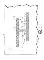
- FIGURE 1 is a greatly enlarged top view of a security mark proximate a visible character on a recipient, according to the exemplary embodiment
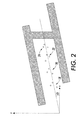
- FIGURES 2 and 3 are greatly enlarged illustrations of other exemplary security marks proximate a visible character
- FIGURE 4 is a further enlarged view of a portion of the security mark of FIGURE 1;
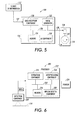
- FIGURE 5 is a functional block diagram of an exemplary embodiment of a system that applies a security mark to a recipient
- FIGURE 6 is a functional block diagram of an exemplary embodiment of a system that detects, extracts and interprets data contained within a security mark;
- FIGURES 7 and 8 are flow charts illustrating an exemplary method of extracting information from a security mark.
- U.S. Application Serial No. 11/317,768 discloses a system which applies a miniature security mark (MSM) to a recipient, such as a digital image or a rendered image.
- MSM miniature security mark
- the MSM is a collection of small, virtually invisible marks having a particular configuration. Such marks have an advantage in that they can be embedded in paper documents that are to be protected (e.g., currency notes) and detected with relatively simple detection techniques. Such detection techniques are thus amenable to use with printing systems with little associated processing capability, such as printers designed specifically for printing camera images by a simple link to the camera or memory card, without requiring access to a stand alone personal computer.
- MSM miniature security marks
- the detection rate of these miniature security marks tends to increase as the number of marks in the collection increases. Where only a limited number of marks is used, false alarm rates tend to increase. For example, 10-15 marks may be used for accurate detection. Additionally, if the marks making up the MSM are placed too close together, they may become visible to the naked eye, which may be undesirable for some applications. These two factors can thus place a constraint on the minimum area occupied by the MSM. Moreover, if the marks comprising the MSM are too close to an edge of the host image, the edge may interfere with detection.
- the techniques described in Application Serial No. 11/317,768 are particularly suited to use in fairly large, smooth (low contrast) regions of an image.
- the collection of marks forming an MSM has a hierarchical structure (a "hierarchical miniature security mark" or HMSM) in which the collection comprises groups of marks whose relative positions and orientations are specified by a set of rules.
- HMSM hierarchical miniature security mark
- the exemplary embodiment allows high accuracy in detection of the HMSM, even when the HMSM includes a relatively few marks or is located in or adjacent to a relatively high contrast area of an image, such as an edge or a visible character.
- a group of marks in the HMSM may be spaced from a second group of the marks by a visible character or portion thereof which does not form a part of the HMSM.
- the rules specifying the inter-group relationships allow the two groups to be identified as part of the HMSM.
- a system for generating a security mark includes a data reception component which receives information.
- a security mark generation component generates at least one security mark configuration based at least in part upon the information from the data reception component.
- the security mark configuration obeys a predetermined set of rules for a hierarchical security mark comprising a collection of marks, including at least one rule which defines a relationship between first and second groups of marks.
- An application component applies the at least one security mark configuration to one or more recipients.
- the security mark generation component may select from a plurality of configurations which obey the set of rules, a configuration which meets predetermined selection criteria.
- the criteria may be defined to output a suitable configuration which can be incorporated into an image such that each group of marks is located in a region which provides sufficient contrast for the marks in the group to be subsequently detectable.
- a method for generating a security mark includes applying a collection of marks to a recipient, the collection of marks including groups of marks which obey predefined inter-group and intra-group spatial relationships.
- the inter-group spatial relationships permit a limited number of different configurations which provides flexibility in the positioning of the groups of marks.
- a system for detection of security marks includes means for extracting a security mark as described herein from a recipient in which it has been embedded and interpreting the mark and optionally for implementing a computer implemented process based on the interpretation.
- a method for detecting a security mark includes inputting image data, processing at least a portion of the image data to identify a collection of marks which potentially comprises a security mark, subjecting the image data to a predetermined set of rules for the security mark including at least one rule which defines a relationship between first and second groups of marks, and, where the image data meets the predetermined set of rules, optionally implementing a computer implemented process.
- a computer readable medium includes instructions, which, when executed on a processor, causes the processor to perform the embedding and/or detection method.
- the inputting of image data may include inputting stored image data from an image data file or scanning a physical document to generate the image data for an image rendered on the document.
- Security marks are considered to be machine readable if techniques are available for automatically obtaining information from signals that include information about the marks. Security marks are considered to be visible if humans generally perceive the marks with an unaided eye.
- a security mark can be any mark (e.g., depression, impression, raised, overlay, combination thereof, or the like) that is applied to a recipient.
- the recipient may be a digital image, such as a graphic, a picture, a body of text, or a physical instantiation of such an image, such as a physical document formed on a physical medium.
- the physical document can be formed by marking the physical medium, such as a physical sheet of paper, plastic, velum, glass, or other suitable physical print media substrate for images, with a marking material, such as ink ortoner, generally referred to as printing.
- the security mark may be applied in the same or a different process from that used to form an image.
- the document may be rendered on a single sheet or multiple sheets by a standard office printer (e.g., ink-jet, laser, etc.) or a large clustered on-demand document printer.
- a physical recipient can comprise any material upon which a security mark can be placed and subsequently detected and extracted.
- an MSM is a security mark which comprises a collection of marks which obey a predetermined set of rules governing relationships between marks in the collection.
- the marks in the collection are generally miniature marks, i.e., marks of a size which while being capable of being machine readable, are too small to be visible.
- the individual marks in the collection may have a size of between about 1 micrometer and several hundred micrometers, and sufficiently spaced from each other such that they are virtually invisible to the naked eye
- a hierarchical MSM (an HMSM) is an MSM in which groups of marks obey a predetermined set of rules governing relationships between groups in the collection.
- the machine-readable information provided by the MSM is decoded, and used to invoke a computer implemented process.
- the computer implemented process may be any suitable process which is implemented automatically as a result of the detection of an HMSM or the detection of an absence of an HMSM.
- the computer implemented process may include permitting/prohibiting copying of the recipient in which the HMSM is detected/not detected, alerting a user by a signal, such as a visible or audible signal, that a recipient can/cannot be copied or advising the user of some other action which should be taken, preventing removal/destruction or otherwise preventing access to the recipient or reuse of the recipient in which the HMSM was detected/not detected, or other computer implemented processes.
- a signal such as a visible or audible signal
- one or more security marks can be placed on the product. Such security marks can be detected and extracted at a later time for verification purposes.
- the security mark can contain information that can be detected, extracted and/or interpreted. Such information can be employed, for example, to prevent counterfeiting by verifying that the information contained within the security mark is accurate.
- the information can be used to verify the authenticity of the recipient to which the security mark is applied.
- the information may be contained in the mark by virtue of the configuration of the miniature marks in the collection which may be associated, e.g., in memory, with particular information from which the MSM is derived.
- the marks in the MSM generally serve two purposes: (1) identification of the collection of marks as a security mark, and (2) providing information, such as information about the recipient which the security mark protects.
- all of the marks in the collection are used for both purposes.
- selected one(s) of the marks are used for only one of the purposes.
- specific aspects of the marks and/or their configuration are used for one or both of these purposes.
- an HMSM is a security mark which comprises a collection of marks (typically miniature marks) with a hierarchical structure.
- the hierarchical structure may include at least two levels, although more than two levels may be employed, such as three or more levels.
- a first level the top level in the exemplary embodiment
- spatial relationships the relative positions and/or orientations
- each of the groups of marks comprising a plurality of marks.
- the spatial relationships of the groups of marks may be defined by a first set of rules.
- a second level of the hierarchy the bottom level in the exemplary embodiment
- spatial relationships between marks within each group are defined. This enables a flexible structure that can fit many different image contexts. In genera, the flexibility is provided by the first level rules.
- the second level rules may constrain the marks within each group to fixed spatial relationships with the other marks in the group.
- each group of marks in the HMSM may have an identical spatial configuration, e.g., in terms of its size and shape, although its orientation in space may be rotated, as compared with other groups.
- the first level rules may permit a plurality of different configurations of the groups of marks, from which a particular configuration which best fits the intended recipient may be selected.
- the first level rules may permit a least two, and in some embodiments, three, four, five, six or more different configurations.
- the configurations may include configurations in which the groups are arranged generally along the same axis and configurations in which two or more groups are aligned generally with a second axis spaced from the first axis (such as in a triangle, square, rectangle, diamond, or other polygonal arrangement).
- some groups may be spaced from other groups by different spacings. The rules thus accommodate different configurations which permit one or more groups to be spaced from another group or groups by a part of the image.
- first level spatial rules define inter-group spatial relationships.
- first level spatial rules may specify one or more of:
- the spacing (distance) between proximate groups may be expressed as a function of a fixed distance, such as kn where k is a variable multiplier and may be an integer which can assume any value between maximum and minimum values and n may be a fixed number of pixels, such as 10, 20, or 50 pixels.
- the spacing may be defined in mutually perpendicular directions (x and y), such as cross process and process directions in an image to be printed.
- the group as a whole may be considered, rather than an individual mark in each group.
- orientation may be considered with respect to one (or more) of the marks in each group.
- the group as a whole may be considered, such as its center, rather than an individual mark in each group.
- the center of a group may be defined in a variety of ways, depending on the arrangement of marks in the group. For example, the center of a group which occupies corners of a triangle may be located at the intersection of lines joining the midpoints of the sides with opposite corners. For less regular shapes, the weighted center of all marks may be taken as the center. Alternatively relative positions of two groups may be considered with respect to one (or more) of the marks in each group.
- the distance rules may be specified to avoid having two groups overlapping each other. Groups overlap when one or more marks of a first group fall within a perimeter of the marks forming another group. By avoiding overlap, each group can be readily identified by the detecting system.
- group centers, or selected reference marks within the groups may be at least a minimum distance from each other so as to avoid a mark of a first group falling within a perimeter defined by the marks of a second group in all of the permitted configurations.
- centers of the groups are spaced by a distance which exceeds a distance between any pair of marks in the group, or exceeds a distance between any mark of a group and the center of the group, e.g., by a factor of at least two.
- First level rules may also include other rules, such as rules which place numerical limitations, e.g.:
- second level spatial rules i.e., rules for a group of marks define intra-group spatial relationships.
- second level rules may specify one or more spatial relationships selected from:
- the second level rules may also specify other features of the marks, such as:
- the rules may require that all of the groups forming the collection have the same set of intra-group relationships to the other groups of marks. In other embodiments, fewer than all the groups of marks have the same intra-group relationship to each other. For example, a rule may specify that a certain specific number of groups or a predefined minimum and/or maximum number of the groups forming the collection obey the same set of intra-group relationships. Additionally, between groups of marks, the groups in the collection may all have the same set of inter-group relationships or one or more groups in the collection of marks may have a different inter-group relationship. Thus the configuration of the marks for each group may or may not be identical. The rules governing a particular hierarchical security mark define which inter-group and intra-group relationships must be obeyed for the collection to be identified as a HMSM of that particular configuration.
- each of a plurality of groups of marks in the collection includes at least three marks.
- at least a first of the groups of marks includes N marks which have the same spatial relationship to each other (i.e., obey the same set of second level spatial relationship rules) as N marks of a second of the groups of marks, where N is an integer which is at least 2 and can be for example, 3, 4, or 5, etc.
- N is less than 20, e.g., less than 10.
- at least P groups of marks have N marks which obey the same set of second level spatial relationship rules, where P is an integer which is at least 2, and can be, for example, 3, 4, 5, or 6, etc.
- P is less than 20, e.g., less than 10.
- At least R of the P groups obey the same set of inter-group rules, where R is an integer which is at least 2 and can be up to P.
- at least nine miniature security marks form an HMSM such as from about 9 to 30 miniature marks, and in one embodiment, about 12-20 miniature marks, which may be in at least three groups.
- each group is identified. Additionally, the relative positions and orientations of the groups are determined to establish whether the rules specified are established. To design the rules that specify the relative orientations and positions among the groups, two considerations are helpful. First, particularly where host images may differ, the rules should provide sufficient flexibility to enable the resulting MSMs to take different configurations that fit into the context of the host image. Second, the rules should also provide enough discriminating power so that the detection errors are within acceptable levels.
- an exemplary security mark 10 in the form of a HMSM is illustrated.
- the security mark 10 is located in an area 12 of an image 14 which is determined to be of an acceptable level of image smoothness for detection of the security mark. Areas of the image considered too dark (i.e., providing insufficient contrast with the marks to permit detection or which are otherwise unsuitable for location of the security marks) are indicated by the hatched area 16.
- area 12 may be a white background area or an area of low contrast
- area 16 may be a portion of text in the image.
- the security mark 10 may be embedded in the image 14 and may be physically embodied on a suitable recipient, e.g., a substrate 17, such as paper.
- the illustrated substrate 17 can be employed within a particular product, such as a document, e.g., a title, a license, a visa, a passport, a bill of currency, a check, or the like.
- a document e.g., a title, a license, a visa, a passport, a bill of currency, a check, or the like.
- a single security mark 10 is illustrated, a plurality of security marks can be applied in substantially any location on the recipient.
- the marks 28, 30, 32 in each group have an identical configuration (specified by second level rules). Specifically, as shown in FIGURE 4, which shows group 18 byway of example, the marks in each group are arranged at corners of an imaginary triangle with a geometric center C and having two sides 34, 36 of equal length a which subtend an angle ⁇ and a third side 38 of length b.
- the intra-group configuration of the marks in a group 18 ignores the orientation of the group of marks in space.
- the marks locations are determined by a set of rules which provide a limited flexibility in the relative positioning of the groups of marks.
- each mark 28, 30, 32 in the collection is represented by an unfilled circle of the same size although it will be appreciated that the marks may have different shapes.
- the marks can be circles, ellipses, regular polyhedra, such as triangles squares, or the like and can have substantially any color outline and/or fill.
- one or more of the marks has a different color, size, and/or shape or other distinguishable feature from other marks in the collection.
- the marks have a size s (expressed in terms of its maximum diameter) which is less than one half of a distance between centers of two most closely adjacent marks in a group such that the space between two marks t exceeds the size s of a mark by a factor of, for example, at least 2 (t ⁇ 2s).
- first level rules are specified by the first level rules as:
- the first level rules in this example are defined such that no group overlaps a second group, e.g., by ensuring at least one of ⁇ x and ⁇ y exceeds the projection of the group ⁇ x g and ⁇ y g in the respective direction ⁇ and ⁇ +90°.
- no two groups in the HMSM are overlapping (fall within the same perimeter) and are readily distinguished as a group.
- Another way to distinguish groups is to specify that, in all cases, a minimum distance between a mark of a first group and a mark of a second group is greater than a maximum distance between two marks within the same group.
- the configurations of FIGURES 2 and 3 also represent HMSMs according to the above specification.
- the flexible configuration makes them readily fit to the different image contents.
- direction ⁇ is about 30° from the x axis.
- a first pair of groups 18, 20 is thus aligned with a first axis x 1 and a second pair of groups 22, 24 is thus aligned with a second axis x 2 .
- Axis x 1 is spaced from and parallel with axis x 2 .
- rules for detection of the security mark may specify latitude limits within which the above rules are considered to be obeyed.
- the value of the latitude limit ⁇ selected may depend on the capabilities of the MSM detection system and on the degree of tolerance for false positives, as well as the accuracy of the rendering device and/or the smoothness of the substrate on which the HMSM is rendered.
- the second level rules in the illustrated embodiment specify:
- some of the second level rules such as the attributes and values of a and ⁇ may have an associated latitude limit for detection, although in general, the value of N is not permitted to vary within latitude limits.
- a collection of marks which simultaneously satisfies all the preselected rules for a given hierarchical security mark i.e., within the predefined latitude limits is recognized as an acceptable configuration of the hierarchical security mark.
- Some of the marks in the HMSM may be anchor marks, as described in U.S. Application Serial No. 11/317,768 .
- the anchor marks may provide two reference points for the MSM configuration. Such reference points allow data to be extracted regardless of the scale, orientation, truncation, image degradation, or the like of the security mark.
- systems employed to extract data from the security mark are not dependent on a perfect, properly oriented security mark in order to extract data contained therein. As a result, recipient handling does not have to be constrained.
- the anchor marks may have a different size, shape, color, or other distinguishable feature from the remaining marks ("data marks").
- the anchor marks may be in the same group or in different groups.
- a security mark has a MSM configuration that includes at least one data mark per group and at least one anchor mark per group.
- the marks may have different colors and/or shapes.
- the anchor marks within an MSM configuration have at least one attribute (e.g., size, shape, color, etc.) that is different from the data mark(s) in the group.
- no anchor mark can have all the same attributes of any data mark.
- the hierarchical structure described above finds application in the protection of documents, such as counterfeit protection. It can also be applied to general digital watermarking. Conventionally, certain regions in an image are considered to be not suitable for embedding digital watermarks. For example, totally white regions tend to be difficult to hide watermarking noise. Very dark regions tend to make watermarks more difficult to survive the printing/scanning process. By decomposing a digital watermark of large size into several smaller sub-watermarks, these problems are more readily overcome. The additional rules for specifying the relative orientations and positions among the groups help to partially compensate for the information loss caused by the decomposition.
- Anchor marks can be employed, as described in copending Application Serial No. 11/317,768. However, the use of a hierarchical structure in the present application reduces the number of marks which provide a given detection accuracy, such that anchor marks are generally not needed.
- the marks in the hierarchical security mark can be used, collectively or individually, to represent information.
- one or more of the location(s), size(s), color(s) and/or shape(s) of the one or more data marks and/or their inter/intra group spatial relationships can designate the information contained therein.
- information can be stored in and extracted from a HMSM configuration utilizing one or more algorithms.
- the algorithms may comprise processing instructions which compare one or more of the location(s), size(s), color(s), shape(s) of the one or more data marks and/or their inter/intra group spatial relationships and/or number of groups embedded in a recipient with those of one or more stored values for HMSMs which are associated in memory with one or more stored parameters.
- the stored parameters may enable authentication of a document, e.g. by providing information identifying the document in which the HMSM is intended to be embedded, e.g.: a 10 dollar bill; a passport or other travel document issued in a particular year or from a particular issuing office; or identify the owner or source of the document.
- the stored parameters may identify whether the document may be copied, e.g., by identifying the document as a copyrighted document or a security document in which copying is limited in some way. Additional groups of marks may be provided to increase the amount of information. For example, all currency denominations may have a HMSM as exemplified in FIGURES 1 to 3. A fifth group of marks may be added to the four for denominations above a certain value.
- the illustrated system 100 includes a source of information 110 which supplies information 112 to be embedded in a recipient 114 to a generating component 116, which generates a HMSM in accordance with the information, and an application component 118, in communication with the MSM generation component, for embedding the generated HMSM in an image to be applied to recipient 114.
- the illustrated generating component 116 includes a data reception component 120, which receives the input information 112, a processing component 122, which executes instructions for generating a security mark based on the received information, and a memory 124 which stores the processing instructions, all interconnected by a data/control bus 126.
- memory 124 may be combined with processor 122 as a single chip.
- Memory 124 may include data reception component 120.
- the MSM generating component 116 may be any suitable computing device for processing and storing data, such as a general purpose computer or combination processor and memory device. In one embodiment, the MSM generating component 116 may form a part of a dedicated device, such as a printer 118.
- the data reception component 120 can comprise memory for storing the information received from the source of information and may also store a set of rules for the security mark which are developed by the processor based on the information.
- the memory may represent any type of computer readable medium which incorporates alterable memory.
- the alterable memory whether volatile or non-volatile, can be implemented by using any one or more of static or dynamic RAM, a floppy disk and disk drive, a writeable or rewriteable optical disk and disk drive, a hard drive, flash memory or the like.
- the data reception component 120 receives information data from one or more sources 110. Such sources can be one or more databases, processing components, etc.
- Data received by the reception component 120 can be representative of substantially any desired quantity or quality such as origin of manufacture, date, time, serial number, currency value, combination thereof or simply an arbitrary alphanumeric string.
- the data is proprietary and may be encoded such that only a limited number of users can interpret the data. Such information can be utilized to verify the authenticity of the recipient to which the security mark is applied.
- the processing component 122 can be any suitable processing component which can convert received data into at least one hierarchical miniature security mark (HMSM)which is placed in a particular configuration. Suitable processing components are instantiated in general purpose computers or dedicated devices. Information from the data reception component 120 can be employed to generate one or more security marks.
- the marks that comprise an HMSM configuration can be composed via one or more algorithms stored in memory 124 that convert the received data to a set of rules governing permitted configurations of marks that are representative of the received data. Additionally, the processor may derive a set of permitted configurations which obey the rules.
- the algorithm can utilize one or more equations, methodologies, work flows, or the like to determine one or more of the locations, sizes and shapes of one or more marks in the HMSM. Such a determination can be made based at least in part upon one or more aspects of one or more disparate marks.
- the algorithms can employ substantially any method to determine the location, size, shape, etc. of the marks within a prospective HMSM configuration. For example, key dependency, mathematical morphology, etc. can be employed. Algorithms utilizing mathematical morphology can process an image utilizing a structuring element, erosion and/or dilation, for example. Informed embedding can be employed utilizing blind extraction. In one example, various techniques are employed to create compact non-authentic regions and to remove noise due to high quality compression from a false detection map. Utilizing mathematical morphology, the tampered regions can be located and noise (e.g., from lossy compression, etc.) is reduced. In another embodiment, an algorithm that creates a geometrically invariant feature based security mark is created. Such a mark remains constant under rotation, scale, translation, etc.
- the memory component 124 can store one or more algorithms, look up tables, or the like for generating a particular MSM configuration. New algorithms to be employed by the security mark generation component 116 can be transmitted to the memory component 124. In this manner, algorithms can be stored, viewed, edited, organized and retrieved for subsequent use. Selection of an algorithm can be based on a plurality of factors such as data source, user preference, time constraints, footprint constraints, data constraints, surface type, and the like.
- the memory 124 may be implemented using any appropriate combination of alterable, volatile or non-volatile memory or non-alterable, or fixed, memory.
- the alterable memory whether volatile or non-volatile, can be implemented by using any one or more of static or dynamic RAM, a floppy disk and disk drive, a writeable or rewriteable optical disk and disk drive, a hard drive, flash memory or the like.
- the non-alterable or fixed memory can be implemented using anyone or more of ROM, PROM, EPROM, EEPROM, and gaps in optical ROM disk, such as a CD ROM or DVD ROM disk and disk drive, or the like.
- the source of information 112, HMSM generator 116, and application component 118 may be interconnected by links 127, 128 for communication therebetween.
- Suitable links include one or more of wired and wireless links, internet or intranet connections, or the like.
- an artificial intelligence (Al) component 130 can be employed to select one or more appropriate algorithms from a set of available algorithms.
- the Al component 130 can employ information received from one or more sources (e.g., databases, processors, machine control systems, etc.) to determine an appropriate algorithm.
- one or more parameters can be detected and employed to determine an appropriate algorithm.
- the appropriate algorithm can be determined by machine learning wherein one or more training sets of data with examples of desired results and/or undesired results for data format and/or processing techniques can be utilized to train the system.
- initial conditions based on one or more features that indicate desired results, can be utilized. Such initial conditions can be adjusted over time and associated with returned results in order to improve discrimination.
- the processor 116 may select one of the permitted HMSM configurations, based on the image to which is to be embedded. For example, the processor may apply one or more criteria to select a configuration which is machine-readable and yet which is visually unobtrusive in the recipient in which it is to be embedded.
- the application component 118 can apply one or more security marks received from the security mark generation component 112 to one or more recipients.
- the application component 118 may include a printer or other device capable of rendering an image in a tangible medium or an electronic medium.
- the application component 118 is embodied in a printer that can place a MSM configuration on a physical recipient 114 (e.g., paper, velum, acetate, etc.) based at least in part upon commands received from the security mark generation component 116.
- a mark applying component 132 such as a print head, ink jet, an applicator, photoconductive element of a xerographic device, or the like can and distribute a marking medium 134, such as ink or toner, in specified locations to create a particular MSM configuration.
- the mark applying component 132 may move to one or more locations relative to the recipient 122 during application of the HMSM.
- the application component 116 comprises a laser marking system that removes and/or discolors a surface of the recipient in order to create a particular HMSM configuration.
- the security mark applying component 116 can be embodied in a conventional printer, such as an inkjet or xerographic printer which includes an image applying component which applies the HMSM as part of an image to be protected by the MSM.
- a printer can comprise any device for rendering an image on print media, such as a copier, laser printer, bookmaking machine, facsimile machine, or a multifunction machine.
- the mark applying component 116 may apply the security mark to a digital image by embedding the MSM as data in the image data.
- the image data can be transformed by changing gray levels corresponding to colorant values of pixels of the image.
- the application component 116 can be substantially any device that can create one or more marks on a recipient.
- FIGURE 6 illustrates a system 200 that retrieves a security mark (e.g., an HMSM configuration) from a recipient, associates information with the security mark (i.e., interprets it), and may also invoke a computer implemented process based on the interpretation.
- the illustrated system 200 includes a detection component 210, and a processor 212 comprising an extraction component 214, a memory 216, which stores one or more algorithms, an interpretation component 218, and an optionally an implementation component 220 which implements a process based on information from the interpretation component 218.
- the processing components 214, 218, and 220 and memory may be connected by a data/control bus 222.
- the processor 212 may comprise a general purpose computer or may form a part of a dedicated device for implementing a specific computer implemented process, such as a banknote verification device, passport verification device, printer, or the like.
- the exemplary system 200 can detect one or more security marks that are applied to a recipient, extract the one or more security marks, and interpret the data contained within the one or more security marks, and optionally implement a process based on the interpretation.
- the memory 216 can store one or more algorithms utilized by the extraction component to extract the one or more security marks applied to the recipient and/or by the interpretation component for interpreting the extracted mark.
- the detection component 210 can be employed to detect one or more security marks located on a recipient.
- a suitable detection component 210 may include an optical input device capable of capturing information from an entire document or from a localized region of a recipient, such as a part of a document, and generating a signal representative of the captured region, such as gray levels for pixels in the region.
- the detection component 210 may include a processing component which executes processing instructions for evaluating the signals. For example, the detection component may be preprogrammed such that it searches for particular configurations, specific locations, after a predetermined condition is met, and so forth. In this manner, the detection component 210 can be customized based on one or more user requirements.
- the detection component 210 can be substantially any device that can scan a recipient surface and locate one or more putative MSM configurations.
- the detection component 210 comprises an optical detection system that can scan a particular field utilizing a charge coupled device (CCD) array.
- CCD charge coupled device
- One or more predetermined thresholds can be established related to one or more pixels within an array. Such array can be scrutinized such that pixels which meet the one or more predetermined thresholds (e.g., particular gray level, brightness, size, etc.) can be identified.
- the detection component 210 can process the identified pixels and determine whether a group of markings indicative of an MSM configuration is present.
- the optical detection system can select a region of an image for analysis where an MSM is expected to be located, e.g., the optical detection system may zoom in on the surface of a bill of currency and detect the location of one or more security marks and the data contained therein.
- the extraction component 214 can employ one or more algorithms to extract information contained within one or more security marks. Algorithms can contain one or more formulae, equations, methods, etc. to interpret data represented by a particular security mark.
- Algorithms can contain one or more formulae, equations, methods, etc. to interpret data represented by a particular security mark.
- the extraction component 214 can analyze the location of the marks in a group relative to each other and relative to other groups of marks in the collection. The size, shape, color, orientation, etc. of the marks can also be analyzed to extract information contained within the one or more MSM configurations. In addition, the extraction component can analyze the location of any anchor marks relative to each other to insure that an MSM configuration exists in a particular location.
- the memory 216 can be employed to store, organize, edit, view, and retrieve one or more algorithms for subsequent use.
- the extraction component 214 can retrieve one or more algorithms from the memory 216 to determine the information contained within a MSM configuration.
- the extraction component 214 can determine the appropriate algorithm, methodology, etc. to extract information from one or more security marks and transmit such information to the memory 216 for subsequent use.
- the interpretation component 218 can determine the meaning of data extracted from one or more putative security marks by the extraction component 214. Such a determination can be made based on one or more conditions such as the location of the security mark, the recipient upon which the security mark is applied, the location of the system, one or more predetermined conditions, and the like. In addition, a look up table, a database, etc. can be employed by the interpretation component 218 to determine the meaning of data extracted from a security mark.
- the security mark is related to the recipient upon which the security mark is applied. For instance, a security mark which corresponds to a data string "5jrwm38f6ho" may have a different meaning when applied to a one hundred dollar bill versus a one hundred euro bill.
- the interpretation component 218 compares information derived from the security mark with other information concerning the recipient.
- the information concerning the recipient may be stored on memory and/or may be extracted from the recipient.
- the detection component may detect that the recipient comprises an image of a one hundred dollar bill or this information may be input by an operator of the system.
- the interpretation component may determine, from the look up table, whether information derived from the security mark properly corresponds to a one hundred dollar bill.
- the implementation component 220 can automatically implement a computer implemented process based on information from the interpretation component. For example, if the interpretation component 218 determines that there is no security mark or collection of marks corresponding to a one hundred dollar bill on the recipient, the implementation component 220 may send a signal to an associated device, cause an alarm to sound, generate data indicating that the bill is suspected of being counterfeit, or other process based on the interpretation. For example, when the presence of a particular security mark is detected which is interpreted as indicative of a copyrighted document, the implementation component 220 signals an associated printer 224 which may prevent copying of the document on the printer.
- FIGURE 7 illustrates a method of generating a security mark which may be performed using the system illustrated in FIGURE 6.
- the method is described as a series of steps. However, it is to be appreciated that the method may comprise fewer, more, or different steps and that the steps need not be performed in the order illustrated.
- the method begins at step S300.
- information is received from one or more sources. Such information can contain data pertaining to source, date, time, serial number, sequential code, etc. In one example, the information is a proprietary alphanumeric sequence that is known only to a limited number of parties.
- security mark rules are developed which permit a plurality of HMSM configurations for a security mark, based at least in part upon the information received at step S302.
- the security mark rules/configurations can be generated utilizing one or more algorithms that can determine the size, shape, color, orientation and location of the marks and groups of marks according to first and second level hierarchical rules.
- the algorithm may be selected based on the information received in step S302.
- one of the permitted configurations is selected based on based on predetermined selection criteria, including criteria based on characteristics of the image into which it is to be embedded.
- the characteristics may include, for example, the morphology (color, shape, size, etc.) and locations of suitable areas 14 and/or unsuitable areas 16 in the region of the image to which the security mark is to be embedded.
- the security mark is applied to a recipient.
- Application of the security mark can be accomplished utilizing substantially any device such as a printing platform, a laser marker, a pin stamp marker, etc.
- substantially any methodology such as xerography, printing, image transfer, etc. can be employed to apply the security mark to a recipient, such as paper.
- step S308 may comprise simply embedding the security mark in a digital image. The method ends at step S310.
- FIGURE 8 illustrates a detection method, which may occur at some time subsequent to step S308.
- the method of FIGURE 8 may be performed on the recipient marked with the security mark described above in FIGURE 7 or on a document which has a different security mark or no security mark.
- the method starts at step S320.
- a recipient which may or may not comprise a security mark is received.
- the recipient is analyzed.
- This analysis can determine the context wherein a security mark may be employed. For example, the type of recipient, the location of the analysis, the material that comprises the recipient, text and/or images placed on the recipient, etc. can be determined. In one example, the same security mark may have different meanings related to the recipient upon which it is placed.
- a putative security mark where present, may be detected. Detection can be performed, in part, by a number of methods such as those using optical systems, including video systems, and/or human detection. In this manner, the location, size, orientation, etc. of the security mark can be determined.
- step S326 includes examination of pixels in a region of an image where a security mark, where present, should be located and determining whether any of those pixels singly or in combination have grey levels which generally correspond to marks of a security mark.
- the putative security mark (e.g., a collection of marks which may correspond to a security mark) is extracted to determine the data contained therein. Extraction of the security mark can be accomplished by one or more algorithms, formulae, equations, methods, etc. to interpret data represented by a particular security mark.
- the security mark includes a HMSM configuration wherein data conforms to one or more hierarchical rules.
- analysis can be performed to determine the location of the data marks relative to each other and the relationship(s) between groups of marks.
- the size, shape, color, orientation, etc. of the marks can also be analyzed to extract information contained within the one or more HMSM configurations. In this step, different configurations of the same HMSM are considered to be identical and thus to represent identical information.
- the information extracted from the putative security mark is interpreted.
- information Once information has been extracted from the security mark, it is interpreted to determine its meaning.
- Such interpretation can be contextual, as the same information extracted from various disparate contexts can have different meanings.
- the same alphanumeric string extracted from a security mark on a passport can have a different meaning than on a bill of currency.
- a computer implemented process may be implemented based on the interpretation made at step S330.
- the method ends at step S332.
- HMSMs are embedded in paper documents that are to be protected.
- the MSM detectors in the imaging system may recognize the embedded HMSM marks and defeat attempts to copy.
- the exemplary embodiment has advantages in that it enables a relatively small number of marks to be inobtrusively disposed in a document and detected with high levels of accuracy using relatively simple and inexpensive detectors.
Landscapes
- Engineering & Computer Science (AREA)
- Theoretical Computer Science (AREA)
- Multimedia (AREA)
- Signal Processing (AREA)
- Physics & Mathematics (AREA)
- General Physics & Mathematics (AREA)
- Computer Hardware Design (AREA)
- General Engineering & Computer Science (AREA)
- Editing Of Facsimile Originals (AREA)
- Image Processing (AREA)
- Image Analysis (AREA)
- Mobile Radio Communication Systems (AREA)
- Facsimile Image Signal Circuits (AREA)
Applications Claiming Priority (1)
| Application Number | Priority Date | Filing Date | Title |
|---|---|---|---|
| US11/472,695 US7715057B2 (en) | 2006-06-22 | 2006-06-22 | Hierarchical miniature security marks |
Publications (2)
| Publication Number | Publication Date |
|---|---|
| EP1901226A2 true EP1901226A2 (de) | 2008-03-19 |
| EP1901226A3 EP1901226A3 (de) | 2008-07-16 |
Family
ID=38873276
Family Applications (1)
| Application Number | Title | Priority Date | Filing Date |
|---|---|---|---|
| EP07110368A Ceased EP1901226A3 (de) | 2006-06-22 | 2007-06-15 | Hierarchische Miniatur-Sicherheitsmarkierungen |
Country Status (5)
| Country | Link |
|---|---|
| US (1) | US7715057B2 (de) |
| EP (1) | EP1901226A3 (de) |
| JP (1) | JP4801008B2 (de) |
| KR (1) | KR101287811B1 (de) |
| CN (1) | CN101094286B (de) |
Families Citing this family (4)
| Publication number | Priority date | Publication date | Assignee | Title |
|---|---|---|---|---|
| DE102005058006A1 (de) * | 2005-12-05 | 2007-06-06 | Siemens Ag | Verfahren und Peer-Netzwerk zur Ermittlung der Peer-Netzwerk-Herkunftsstadion einer Datei |
| US8056821B2 (en) | 2006-10-18 | 2011-11-15 | Xerox Corporation | Security marks simulating natural defects for embedding information in documents |
| EP2417558A4 (de) * | 2009-05-21 | 2012-12-05 | Hewlett Packard Development Co | Erzeugung eines individuellen glyph, system und verfahren zum untersuchen von individuellen glyphen |
| US8144925B2 (en) * | 2010-08-24 | 2012-03-27 | Seiko Epson Corporation | Mapping based message encoding for fast reliable visible watermarking |
Citations (1)
| Publication number | Priority date | Publication date | Assignee | Title |
|---|---|---|---|---|
| EP1059800B1 (de) | 1999-06-09 | 2005-11-02 | Xerox Corporation | Digitales Abbildungsverfahren und Vorrichtung zur Detektion von Dokumentsicherheitsmerkmalen |
Family Cites Families (13)
| Publication number | Priority date | Publication date | Assignee | Title |
|---|---|---|---|---|
| US6345104B1 (en) * | 1994-03-17 | 2002-02-05 | Digimarc Corporation | Digital watermarks and methods for security documents |
| US6522770B1 (en) * | 1999-05-19 | 2003-02-18 | Digimarc Corporation | Management of documents and other objects using optical devices |
| US6067374A (en) | 1997-11-13 | 2000-05-23 | Xerox Corporation | Seal detection system and method |
| JP2000013585A (ja) * | 1998-06-19 | 2000-01-14 | Sony Corp | 付加情報の重畳装置、付加情報の重畳方法、画像情報記録装置および画像情報記録方法 |
| US6542629B1 (en) * | 1999-07-22 | 2003-04-01 | Xerox Corporation | Digital imaging method and apparatus for detection of document security marks |
| JP2001211319A (ja) * | 2000-01-28 | 2001-08-03 | Fuji Photo Film Co Ltd | 画像処理方法 |
| KR100396327B1 (ko) * | 2000-10-13 | 2003-09-02 | (주)디지탈이노텍 | 바코드 워터마킹 방법 |
| US7002704B1 (en) * | 2000-11-06 | 2006-02-21 | Xerox Corporation | Method and apparatus for implementing anti-counterfeiting measures in personal computer-based digital color printers |
| KR100405828B1 (ko) | 2002-02-01 | 2003-11-14 | 주식회사 마크애니 | 위변조의 방지가 가능한 문서를 제작하는 장치 및 방법,그리고 상기 문서를 인증하는 장치 및 방법 |
| KR100491649B1 (ko) | 2003-04-07 | 2005-05-27 | 주식회사 에스엠티 | 다차원 바코드의 워터마크 삽입·검출 시스템 및 그삽입·검출 방법 |
| JP4783003B2 (ja) | 2003-11-28 | 2011-09-28 | 株式会社東芝 | 個人認証媒体発行装置および個人認証媒体発行方法 |
| US7543758B2 (en) * | 2005-12-20 | 2009-06-09 | Xerox Corporation | Document localization of pointing actions using disambiguated visual regions |
| US9033371B2 (en) * | 2005-12-23 | 2015-05-19 | Xerox Corporation | Counterfeit prevention using miniature security marks |
-
2006
- 2006-06-22 US US11/472,695 patent/US7715057B2/en not_active Expired - Fee Related
-
2007
- 2007-06-15 EP EP07110368A patent/EP1901226A3/de not_active Ceased
- 2007-06-18 JP JP2007159770A patent/JP4801008B2/ja not_active Expired - Fee Related
- 2007-06-21 CN CN2007101122059A patent/CN101094286B/zh not_active Expired - Fee Related
- 2007-06-22 KR KR1020070061605A patent/KR101287811B1/ko not_active Expired - Fee Related
Patent Citations (1)
| Publication number | Priority date | Publication date | Assignee | Title |
|---|---|---|---|---|
| EP1059800B1 (de) | 1999-06-09 | 2005-11-02 | Xerox Corporation | Digitales Abbildungsverfahren und Vorrichtung zur Detektion von Dokumentsicherheitsmerkmalen |
Also Published As
| Publication number | Publication date |
|---|---|
| CN101094286A (zh) | 2007-12-26 |
| US7715057B2 (en) | 2010-05-11 |
| CN101094286B (zh) | 2011-05-25 |
| US20070297012A1 (en) | 2007-12-27 |
| EP1901226A3 (de) | 2008-07-16 |
| KR20070121596A (ko) | 2007-12-27 |
| JP4801008B2 (ja) | 2011-10-26 |
| KR101287811B1 (ko) | 2013-07-26 |
| JP2008005489A (ja) | 2008-01-10 |
Similar Documents
| Publication | Publication Date | Title |
|---|---|---|
| US8888010B2 (en) | Detection of security marks simulating natural defects for embedding information in documents | |
| US8335342B2 (en) | Protecting printed items intended for public exchange with information embedded in blank document borders | |
| EP1906645B1 (de) | Vorrichtung zur Einbettung digitaler Wasserzeichen und Vorrichtung zur Erkennung von digitalen Wasserzeichen | |
| US8224019B2 (en) | Embedding information in document blank space | |
| US8243982B2 (en) | Embedding information in document border space | |
| EP1432234B1 (de) | Systeme und Verfahren zur Bereitstellung von ausgedruckten Sicherheitsdokumenten sowie zur Validierung von solchen Dokumenten | |
| US6983056B1 (en) | Method and device for embedding and detecting watermarking information into a black and white binary document image | |
| EP1953710B1 (de) | Fälschungsabschreckung mittels verstreuter Miniatursicherheitsmarkierungen | |
| JP5536815B2 (ja) | 微小セキュリティマークを利用した偽造防止装置及び方法 | |
| CA2618738C (en) | System and method for embedding dispersed miniature security marks | |
| US8373895B2 (en) | Prevention of unauthorized copying or scanning | |
| US11979537B1 (en) | Incorporation of source-identifying information in scanned documents | |
| EP1901226A2 (de) | Hierarchische Miniatur-Sicherheitsmarkierungen | |
| EP1887532B1 (de) | System und Verfahren zur Detektion von Miniatursicherheitskennzeichen | |
| US7792324B2 (en) | System and method for embedding miniature security marks |
Legal Events
| Date | Code | Title | Description |
|---|---|---|---|
| PUAI | Public reference made under article 153(3) epc to a published international application that has entered the european phase |
Free format text: ORIGINAL CODE: 0009012 |
|
| AK | Designated contracting states |
Kind code of ref document: A2 Designated state(s): AT BE BG CH CY CZ DE DK EE ES FI FR GB GR HU IE IS IT LI LT LU LV MC MT NL PL PT RO SE SI SK TR |
|
| AX | Request for extension of the european patent |
Extension state: AL BA HR MK YU |
|
| PUAL | Search report despatched |
Free format text: ORIGINAL CODE: 0009013 |
|
| AK | Designated contracting states |
Kind code of ref document: A3 Designated state(s): AT BE BG CH CY CZ DE DK EE ES FI FR GB GR HU IE IS IT LI LT LU LV MC MT NL PL PT RO SE SI SK TR |
|
| AX | Request for extension of the european patent |
Extension state: AL BA HR MK RS |
|
| RIC1 | Information provided on ipc code assigned before grant |
Ipc: G06T 1/00 20060101ALI20080612BHEP Ipc: H04N 1/32 20060101AFI20080612BHEP |
|
| 17P | Request for examination filed |
Effective date: 20090116 |
|
| AKX | Designation fees paid |
Designated state(s): DE FR GB |
|
| 17Q | First examination report despatched |
Effective date: 20090312 |
|
| R17C | First examination report despatched (corrected) |
Effective date: 20090317 |
|
| 17Q | First examination report despatched |
Effective date: 20100329 |
|
| 17Q | First examination report despatched |
Effective date: 20100407 |
|
| 17Q | First examination report despatched |
Effective date: 20110826 |
|
| STAA | Information on the status of an ep patent application or granted ep patent |
Free format text: STATUS: THE APPLICATION HAS BEEN REFUSED |
|
| 18R | Application refused |
Effective date: 20170118 |