EP1901154A1 - Variable flow range type flow control device - Google Patents
Variable flow range type flow control device Download PDFInfo
- Publication number
- EP1901154A1 EP1901154A1 EP06767569A EP06767569A EP1901154A1 EP 1901154 A1 EP1901154 A1 EP 1901154A1 EP 06767569 A EP06767569 A EP 06767569A EP 06767569 A EP06767569 A EP 06767569A EP 1901154 A1 EP1901154 A1 EP 1901154A1
- Authority
- EP
- European Patent Office
- Prior art keywords
- flow rate
- flow
- fluid
- orifice
- rate control
- Prior art date
- Legal status (The legal status is an assumption and is not a legal conclusion. Google has not performed a legal analysis and makes no representation as to the accuracy of the status listed.)
- Withdrawn
Links
- 239000012530 fluid Substances 0.000 claims abstract description 125
- 238000011144 upstream manufacturing Methods 0.000 claims abstract description 11
- 238000001514 detection method Methods 0.000 claims description 16
- 238000004891 communication Methods 0.000 claims description 6
- 238000009434 installation Methods 0.000 abstract description 3
- 239000007789 gas Substances 0.000 description 21
- 238000004519 manufacturing process Methods 0.000 description 13
- 230000003321 amplification Effects 0.000 description 6
- 238000003199 nucleic acid amplification method Methods 0.000 description 6
- 239000004065 semiconductor Substances 0.000 description 6
- 238000006243 chemical reaction Methods 0.000 description 5
- 238000010586 diagram Methods 0.000 description 4
- 238000000034 method Methods 0.000 description 4
- 238000012937 correction Methods 0.000 description 3
- 235000013305 food Nutrition 0.000 description 2
- 239000000825 pharmaceutical preparation Substances 0.000 description 2
- 229940127557 pharmaceutical product Drugs 0.000 description 2
- 239000000126 substance Substances 0.000 description 2
- 230000015556 catabolic process Effects 0.000 description 1
- 239000013256 coordination polymer Substances 0.000 description 1
- 238000006731 degradation reaction Methods 0.000 description 1
- 230000000694 effects Effects 0.000 description 1
- 238000012423 maintenance Methods 0.000 description 1
- 238000012545 processing Methods 0.000 description 1
- 230000004043 responsiveness Effects 0.000 description 1
Images



Classifications
-
- G—PHYSICS
- G01—MEASURING; TESTING
- G01F—MEASURING VOLUME, VOLUME FLOW, MASS FLOW OR LIQUID LEVEL; METERING BY VOLUME
- G01F1/00—Measuring the volume flow or mass flow of fluid or fluent solid material wherein the fluid passes through a meter in a continuous flow
- G01F1/05—Measuring the volume flow or mass flow of fluid or fluent solid material wherein the fluid passes through a meter in a continuous flow by using mechanical effects
- G01F1/34—Measuring the volume flow or mass flow of fluid or fluent solid material wherein the fluid passes through a meter in a continuous flow by using mechanical effects by measuring pressure or differential pressure
- G01F1/36—Measuring the volume flow or mass flow of fluid or fluent solid material wherein the fluid passes through a meter in a continuous flow by using mechanical effects by measuring pressure or differential pressure the pressure or differential pressure being created by the use of flow constriction
- G01F1/363—Measuring the volume flow or mass flow of fluid or fluent solid material wherein the fluid passes through a meter in a continuous flow by using mechanical effects by measuring pressure or differential pressure the pressure or differential pressure being created by the use of flow constriction with electrical or electro-mechanical indication
-
- G—PHYSICS
- G05—CONTROLLING; REGULATING
- G05D—SYSTEMS FOR CONTROLLING OR REGULATING NON-ELECTRIC VARIABLES
- G05D7/00—Control of flow
- G05D7/06—Control of flow characterised by the use of electric means
- G05D7/0617—Control of flow characterised by the use of electric means specially adapted for fluid materials
- G05D7/0629—Control of flow characterised by the use of electric means specially adapted for fluid materials characterised by the type of regulator means
- G05D7/0635—Control of flow characterised by the use of electric means specially adapted for fluid materials characterised by the type of regulator means by action on throttling means
- G05D7/0641—Control of flow characterised by the use of electric means specially adapted for fluid materials characterised by the type of regulator means by action on throttling means using a plurality of throttling means
-
- G—PHYSICS
- G05—CONTROLLING; REGULATING
- G05D—SYSTEMS FOR CONTROLLING OR REGULATING NON-ELECTRIC VARIABLES
- G05D7/00—Control of flow
-
- G—PHYSICS
- G01—MEASURING; TESTING
- G01F—MEASURING VOLUME, VOLUME FLOW, MASS FLOW OR LIQUID LEVEL; METERING BY VOLUME
- G01F1/00—Measuring the volume flow or mass flow of fluid or fluent solid material wherein the fluid passes through a meter in a continuous flow
- G01F1/68—Measuring the volume flow or mass flow of fluid or fluent solid material wherein the fluid passes through a meter in a continuous flow by using thermal effects
- G01F1/684—Structural arrangements; Mounting of elements, e.g. in relation to fluid flow
- G01F1/6842—Structural arrangements; Mounting of elements, e.g. in relation to fluid flow with means for influencing the fluid flow
-
- G—PHYSICS
- G01—MEASURING; TESTING
- G01F—MEASURING VOLUME, VOLUME FLOW, MASS FLOW OR LIQUID LEVEL; METERING BY VOLUME
- G01F1/00—Measuring the volume flow or mass flow of fluid or fluent solid material wherein the fluid passes through a meter in a continuous flow
- G01F1/68—Measuring the volume flow or mass flow of fluid or fluent solid material wherein the fluid passes through a meter in a continuous flow by using thermal effects
- G01F1/684—Structural arrangements; Mounting of elements, e.g. in relation to fluid flow
- G01F1/6847—Structural arrangements; Mounting of elements, e.g. in relation to fluid flow where sensing or heating elements are not disturbing the fluid flow, e.g. elements mounted outside the flow duct
-
- G—PHYSICS
- G01—MEASURING; TESTING
- G01F—MEASURING VOLUME, VOLUME FLOW, MASS FLOW OR LIQUID LEVEL; METERING BY VOLUME
- G01F5/00—Measuring a proportion of the volume flow
- G01F5/005—Measuring a proportion of the volume flow by measuring pressure or differential pressure, created by the use of flow constriction
-
- G—PHYSICS
- G01—MEASURING; TESTING
- G01F—MEASURING VOLUME, VOLUME FLOW, MASS FLOW OR LIQUID LEVEL; METERING BY VOLUME
- G01F7/00—Volume-flow measuring devices with two or more measuring ranges; Compound meters
- G01F7/005—Volume-flow measuring devices with two or more measuring ranges; Compound meters by measuring pressure or differential pressure, created by the use of flow constriction
-
- G—PHYSICS
- G05—CONTROLLING; REGULATING
- G05D—SYSTEMS FOR CONTROLLING OR REGULATING NON-ELECTRIC VARIABLES
- G05D23/00—Control of temperature
- G05D23/19—Control of temperature characterised by the use of electric means
- G05D23/1927—Control of temperature characterised by the use of electric means using a plurality of sensors
-
- G—PHYSICS
- G05—CONTROLLING; REGULATING
- G05D—SYSTEMS FOR CONTROLLING OR REGULATING NON-ELECTRIC VARIABLES
- G05D7/00—Control of flow
- G05D7/06—Control of flow characterised by the use of electric means
- G05D7/0617—Control of flow characterised by the use of electric means specially adapted for fluid materials
- G05D7/0629—Control of flow characterised by the use of electric means specially adapted for fluid materials characterised by the type of regulator means
- G05D7/0635—Control of flow characterised by the use of electric means specially adapted for fluid materials characterised by the type of regulator means by action on throttling means
-
- G—PHYSICS
- G05—CONTROLLING; REGULATING
- G05D—SYSTEMS FOR CONTROLLING OR REGULATING NON-ELECTRIC VARIABLES
- G05D7/00—Control of flow
- G05D7/06—Control of flow characterised by the use of electric means
- G05D7/0617—Control of flow characterised by the use of electric means specially adapted for fluid materials
- G05D7/0629—Control of flow characterised by the use of electric means specially adapted for fluid materials characterised by the type of regulator means
- G05D7/0635—Control of flow characterised by the use of electric means specially adapted for fluid materials characterised by the type of regulator means by action on throttling means
- G05D7/0641—Control of flow characterised by the use of electric means specially adapted for fluid materials characterised by the type of regulator means by action on throttling means using a plurality of throttling means
- G05D7/0647—Control of flow characterised by the use of electric means specially adapted for fluid materials characterised by the type of regulator means by action on throttling means using a plurality of throttling means the plurality of throttling means being arranged in series
-
- Y—GENERAL TAGGING OF NEW TECHNOLOGICAL DEVELOPMENTS; GENERAL TAGGING OF CROSS-SECTIONAL TECHNOLOGIES SPANNING OVER SEVERAL SECTIONS OF THE IPC; TECHNICAL SUBJECTS COVERED BY FORMER USPC CROSS-REFERENCE ART COLLECTIONS [XRACs] AND DIGESTS
- Y10—TECHNICAL SUBJECTS COVERED BY FORMER USPC
- Y10T—TECHNICAL SUBJECTS COVERED BY FORMER US CLASSIFICATION
- Y10T137/00—Fluid handling
- Y10T137/0318—Processes
- Y10T137/0324—With control of flow by a condition or characteristic of a fluid
- Y10T137/0379—By fluid pressure
-
- Y—GENERAL TAGGING OF NEW TECHNOLOGICAL DEVELOPMENTS; GENERAL TAGGING OF CROSS-SECTIONAL TECHNOLOGIES SPANNING OVER SEVERAL SECTIONS OF THE IPC; TECHNICAL SUBJECTS COVERED BY FORMER USPC CROSS-REFERENCE ART COLLECTIONS [XRACs] AND DIGESTS
- Y10—TECHNICAL SUBJECTS COVERED BY FORMER USPC
- Y10T—TECHNICAL SUBJECTS COVERED BY FORMER US CLASSIFICATION
- Y10T137/00—Fluid handling
- Y10T137/7722—Line condition change responsive valves
- Y10T137/7758—Pilot or servo controlled
- Y10T137/7759—Responsive to change in rate of fluid flow
-
- Y—GENERAL TAGGING OF NEW TECHNOLOGICAL DEVELOPMENTS; GENERAL TAGGING OF CROSS-SECTIONAL TECHNOLOGIES SPANNING OVER SEVERAL SECTIONS OF THE IPC; TECHNICAL SUBJECTS COVERED BY FORMER USPC CROSS-REFERENCE ART COLLECTIONS [XRACs] AND DIGESTS
- Y10—TECHNICAL SUBJECTS COVERED BY FORMER USPC
- Y10T—TECHNICAL SUBJECTS COVERED BY FORMER US CLASSIFICATION
- Y10T137/00—Fluid handling
- Y10T137/7722—Line condition change responsive valves
- Y10T137/7758—Pilot or servo controlled
- Y10T137/7759—Responsive to change in rate of fluid flow
- Y10T137/776—Control by pressures across flow line valve
-
- Y—GENERAL TAGGING OF NEW TECHNOLOGICAL DEVELOPMENTS; GENERAL TAGGING OF CROSS-SECTIONAL TECHNOLOGIES SPANNING OVER SEVERAL SECTIONS OF THE IPC; TECHNICAL SUBJECTS COVERED BY FORMER USPC CROSS-REFERENCE ART COLLECTIONS [XRACs] AND DIGESTS
- Y10—TECHNICAL SUBJECTS COVERED BY FORMER USPC
- Y10T—TECHNICAL SUBJECTS COVERED BY FORMER US CLASSIFICATION
- Y10T137/00—Fluid handling
- Y10T137/8593—Systems
-
- Y—GENERAL TAGGING OF NEW TECHNOLOGICAL DEVELOPMENTS; GENERAL TAGGING OF CROSS-SECTIONAL TECHNOLOGIES SPANNING OVER SEVERAL SECTIONS OF THE IPC; TECHNICAL SUBJECTS COVERED BY FORMER USPC CROSS-REFERENCE ART COLLECTIONS [XRACs] AND DIGESTS
- Y10—TECHNICAL SUBJECTS COVERED BY FORMER USPC
- Y10T—TECHNICAL SUBJECTS COVERED BY FORMER US CLASSIFICATION
- Y10T137/00—Fluid handling
- Y10T137/8593—Systems
- Y10T137/86493—Multi-way valve unit
- Y10T137/86718—Dividing into parallel flow paths with recombining
- Y10T137/86734—With metering feature
-
- Y—GENERAL TAGGING OF NEW TECHNOLOGICAL DEVELOPMENTS; GENERAL TAGGING OF CROSS-SECTIONAL TECHNOLOGIES SPANNING OVER SEVERAL SECTIONS OF THE IPC; TECHNICAL SUBJECTS COVERED BY FORMER USPC CROSS-REFERENCE ART COLLECTIONS [XRACs] AND DIGESTS
- Y10—TECHNICAL SUBJECTS COVERED BY FORMER USPC
- Y10T—TECHNICAL SUBJECTS COVERED BY FORMER US CLASSIFICATION
- Y10T137/00—Fluid handling
- Y10T137/8593—Systems
- Y10T137/86493—Multi-way valve unit
- Y10T137/86815—Multiple inlet with single outlet
-
- Y—GENERAL TAGGING OF NEW TECHNOLOGICAL DEVELOPMENTS; GENERAL TAGGING OF CROSS-SECTIONAL TECHNOLOGIES SPANNING OVER SEVERAL SECTIONS OF THE IPC; TECHNICAL SUBJECTS COVERED BY FORMER USPC CROSS-REFERENCE ART COLLECTIONS [XRACs] AND DIGESTS
- Y10—TECHNICAL SUBJECTS COVERED BY FORMER USPC
- Y10T—TECHNICAL SUBJECTS COVERED BY FORMER US CLASSIFICATION
- Y10T137/00—Fluid handling
- Y10T137/8593—Systems
- Y10T137/87265—Dividing into parallel flow paths with recombining
-
- Y—GENERAL TAGGING OF NEW TECHNOLOGICAL DEVELOPMENTS; GENERAL TAGGING OF CROSS-SECTIONAL TECHNOLOGIES SPANNING OVER SEVERAL SECTIONS OF THE IPC; TECHNICAL SUBJECTS COVERED BY FORMER USPC CROSS-REFERENCE ART COLLECTIONS [XRACs] AND DIGESTS
- Y10—TECHNICAL SUBJECTS COVERED BY FORMER USPC
- Y10T—TECHNICAL SUBJECTS COVERED BY FORMER US CLASSIFICATION
- Y10T137/00—Fluid handling
- Y10T137/8593—Systems
- Y10T137/87265—Dividing into parallel flow paths with recombining
- Y10T137/87298—Having digital flow controller
- Y10T137/87306—Having plural branches under common control for separate valve actuators
- Y10T137/87314—Electromagnetic or electric control [e.g., digital control, bistable electro control, etc.]
-
- Y—GENERAL TAGGING OF NEW TECHNOLOGICAL DEVELOPMENTS; GENERAL TAGGING OF CROSS-SECTIONAL TECHNOLOGIES SPANNING OVER SEVERAL SECTIONS OF THE IPC; TECHNICAL SUBJECTS COVERED BY FORMER USPC CROSS-REFERENCE ART COLLECTIONS [XRACs] AND DIGESTS
- Y10—TECHNICAL SUBJECTS COVERED BY FORMER USPC
- Y10T—TECHNICAL SUBJECTS COVERED BY FORMER US CLASSIFICATION
- Y10T137/00—Fluid handling
- Y10T137/8593—Systems
- Y10T137/87265—Dividing into parallel flow paths with recombining
- Y10T137/8741—With common operator
-
- Y—GENERAL TAGGING OF NEW TECHNOLOGICAL DEVELOPMENTS; GENERAL TAGGING OF CROSS-SECTIONAL TECHNOLOGIES SPANNING OVER SEVERAL SECTIONS OF THE IPC; TECHNICAL SUBJECTS COVERED BY FORMER USPC CROSS-REFERENCE ART COLLECTIONS [XRACs] AND DIGESTS
- Y10—TECHNICAL SUBJECTS COVERED BY FORMER USPC
- Y10T—TECHNICAL SUBJECTS COVERED BY FORMER US CLASSIFICATION
- Y10T137/00—Fluid handling
- Y10T137/8593—Systems
- Y10T137/87265—Dividing into parallel flow paths with recombining
- Y10T137/87499—Fluid actuated or retarded
-
- Y—GENERAL TAGGING OF NEW TECHNOLOGICAL DEVELOPMENTS; GENERAL TAGGING OF CROSS-SECTIONAL TECHNOLOGIES SPANNING OVER SEVERAL SECTIONS OF THE IPC; TECHNICAL SUBJECTS COVERED BY FORMER USPC CROSS-REFERENCE ART COLLECTIONS [XRACs] AND DIGESTS
- Y10—TECHNICAL SUBJECTS COVERED BY FORMER USPC
- Y10T—TECHNICAL SUBJECTS COVERED BY FORMER US CLASSIFICATION
- Y10T137/00—Fluid handling
- Y10T137/8593—Systems
- Y10T137/87571—Multiple inlet with single outlet
- Y10T137/87676—With flow control
- Y10T137/87684—Valve in each inlet
Definitions
- the present invention relates to a flow rate control apparatus with a fluid supply system used for semiconductor manufacturing facilities, chemical products manufacturing facilities, pharmaceutical products manufacturing facilities, food products manufacturing facilities, and the like. More particularly, the present invention relates to a flow rate range variable type flow rate control apparatus with which both the expansion of a flow rate control range and the maintenance of high control accuracy can be easily achieved with a pressure type flow rate control apparatus and a thermal type mass flow rate control apparatus.
- a flow rate control range may be divided into a plurality of flow rate areas, e.g. the area for a large flow quantity, the area for a medium flow quantity and the area for a small flow quantity, in order to meet a required flow rate control range.
- This solution involves providing 3 sets of flow rate control apparatuses, each one responsible for the flow rate control of one of each one of the flow rate areas in parallel so that high flow rate control accuracy can be maintained over a wide flow rate control range.
- FIG. 7(a) and Figure 7(b) illustrate one example of the basic structure of the afore-mentioned conventional pressure type flow rate control apparatus FCS.
- a major portion of the pressure type flow rate control apparatus FCS comprises a control valve 2, pressure detectors 6, 27, an orifice 8, flow rate computation circuits 13, 31, a flow rate setting circuit 14, a computation control circuit 16, a flow rate output circuit 12, and the like.
- the afore-mentioned pressure type flow rate control apparatus FCS shown in Figure 7(a) is mainly used either in the case where the ratio P 2 /P 1 of the orifice upstream side gas pressure P 1 and the orifice downstream side gas pressure P 2 is equal to the critical value of a fluid, or in the case where the ratio P2/P1 is lower than the critical value (that is, when a gas flow is constantly under the critical state).
- the afore-mentioned pressure type flow rate control apparatus FCS shown in Figure 7(b) is mainly used for the flow rate control of gases that will be in the flow condition in both the critical and non-critical states.
- the setting value of the flow rate is given by a voltage value as Qe, the flow rate setting signal.
- Qe the flow rate setting signal.
- the flow state of a fluid falling outside the afore-mentioned critical state makes the accuracy of a flow rate control substantially reduced.
- unevenness in quality is caused with semiconductor products.
- a pressure type flow rate control apparatus wherein the flow rate control of a fluid is conducted under a critical state
- the possible range available to achieve flow rate control is substantially narrowed in comparison with the possible range available for a conventional thermal type mass flow rate control apparatus or so-called differential pressure type flow rate control apparatus.
- manufacturing costs of semiconductor manufacturing facilities, and the like go up for the reason that two pressure type flow rate control apparatuses having different flow rate control ranges are required.
- the present invention solves the afore-mentioned problems encountered with a conventional flow rate control apparatus, that is, (a) the difficulty in reducing manufacturing costs of a flow rate control apparatus because it becomes necessary that a plurality of flow rate control apparatuses, having different flow rate ranges, are installed in parallel to secure a prescribed control accuracy in the case where a wide flow rate control range is required and thus are used in the manner of switching them, and solves (b) another problem wherein the pressure type flow rate control apparatus, which is basically used for a flow rate control under a critical condition, encounters a flow rate control range that is gradually reduced in view of the pressure rise on the orifice secondary side, which would ordinarily require a plurality of flow rate control apparatuses having different flow rate ranges to be employed to deal with the matter.
- the present invention as claimed in Claim 1 is basically constituted so that a flow rate is controlled by means of switching fluid for flowing in a large flow quantity range and fluid for flowing in a small flow quantity range in a manner so that fluid passages connected to a flow rate detection part of the flow rate control apparatus are installed at least for small flow quantity and large flow quantity.
- the first embodiment of the present invention makes fluid flowing in the small flow quantity range flow to the flow detection part through the afore-mentioned fluid passage for small flow quantity, switches the detection level of the flow rate control part to a detection level suitable for the detection of fluid flowing in the small flow rate range and also makes fluid flowing in the large flow quantity range flow to the flow detection part through the afore-mentioned fluid passage for large flow quantity, and switches the detection level suitable for the detection of fluid flowing in the large flow quantity range.
- the afore-mentioned fluid flowing in the small flow quantity range is made to flow to one orifice for the flow control of the fluid flowing in the small flow quantity range
- the fluid flowing in the large flow quantity range is made to flow to the other orifice for the flow control of the fluid flowing in the large flow quantity range.
- the present invention as claimed in Claim 3 according to Claim 2, is constituted so that the number of fluid passages arranged in parallel are made to be 2, and there are two orifices provided, one for large flow quantity and the other for small flow quantity, and thus the control range of a fluid's flow rate is switched either to the small flow quantity range or to the large flow quantity range by means of operating a switching valve installed on the fluid passage of the orifice for large flow quantity.
- the present invention is constituted so that 3 different orifices are provided including an orifice for a large flow quantity, an orifice for a medium flow quantity and an orifice for a small flow quantity, and a No.1 switching valve, a No.2 switching valve and the orifice for large flow quantity are provided on one fluid passage in series, while the orifice for small flow quantity and the orifice for medium flow quantity are provided on the other fluid passage, and furthermore, the passage for communication between the afore-mentioned 2 switching valves and the passage for communication between the orifice for small flow quantity and the orifice for medium flow quantity are made to be in communication with each other.
- the present invention is made so that fluid flowing through an orifice of a pressure type flow rate control apparatus is made to be a fluid under a critical condition.
- a thermal type mass flow rate control apparatus comprises a flow rate control valve; a laminar flow element device part; a flow rate sensor part; and the like, wherein temperature changes in proportion to a mass flow rate of a fluid are detected at the flow rate sensor part, and fluid with a certain set flow rate is made to flow out by means of opening/closing a flow rate control valve based on the detected temperature; a fluid passage to the flow rate control valve is made to be more than at least 2 fluid passages arranged in parallel, wherein each of the afore-mentioned parallel passages are provided with both laminar flow elements with different coarseness and flow rate sensors, wherein the afore-mentioned fluid in flowing the small flow quantity range is made to flow to one laminar flow element for flow rate control of fluid flowing in the small flow quantity range, while the afore-mentioned fluid flowing in the large
- the present invention as claimed in Claim 7 according to Claim 6 is constituted so that the number of fluid passages in parallel are made to be 2, and the two laminar flow elements are made to be a coarse laminar flow element for large flow quantity and a fine laminar flow element for small flow quantity, and the control range of fluid flow rate is switched either to the small flow quantity range or to the large flow quantity range by means of operating switching valves respectively provided on both fluid passages.
- the present invention is constituted so that flow rate is controlled in a manner wherein flow rate control is performed by appropriately combining an orifice 8c for a large flow quantity, an orifice 8a for a small flow quantity (or an orifice 8c for a large flow quantity, an orifice 8b for a medium flow quantity and an orifice 8a for a small flow quantity), thus making it possible that highly accurate flow rate control may be achieved over a wide flow rate range with an error of less than 1% of the set point.
- the present invention makes operation of flow rate control simple because a flow rate control range can be automatically selected by operating a switching valve.
- the present invention can be applied to flow rate control of various kinds of fluid supply facilities because of ease of change of the type of gases supplied by making use of a flow factor F.F. in the case wherein flow rate control of fluid is basically under a critical condition.
- FCS pressure type flow rate control apparatus MFC thermal type mass flow rate control apparatus
- FIG. 1 is a block diagram of a flow rate range variable type flow rate control apparatus according to one embodiment of the present invention.
- 1 designates a control part
- 2 designates a control valve
- 3 designates an orifice upstream side (primary side) pipe
- 4 designates a valve driving part
- 5 designates a fluid supply pipe
- 6 designates a pressure sensor
- 8a designates an orifice for a small flow quantity
- 8b designates an orifice for a medium flow quantity
- 8c designates an orifice for a large flow quantity
- 32, 33 designate switching electro-magnetic valves
- 34, 35 designate switching valves.
- the control part 1, the control valve 2, the valve driving part 4, the pressure sensor 6, and the like, of the afore-mentioned pressure type flow rate control apparatus have been disclosed.
- flow rate input/output signals i.e., an input signal of a set flow rate, an output signal of a controlled flow rate ⁇ DC 0-5V
- terminals Qe, Qo i.e., a power supply terminal ( ⁇ DC 15V) E
- input terminals S L , S M , S s for providing a controlled flow rate switching command signal.
- the afore-mentioned switching electro-magnetic valves 32, 33 which have been disclosed, are air operation type electro-magnetic valves.
- switching signals C 1 , C 2 are inputted from the control part 1 so that switching electro-magnetic valves 32, 33 start working and a driving gas (0.4 ⁇ 0.7 MPa) Gc is supplied.
- the driving gas Gc is supplied to valve driving parts 34a, 35a of the switching valves, and the switching valves 34, 35 start operating for opening and closing.
- operation of both switching valves 34, 35 is detected by proximity switches 34b, 35b installed on the valve driving parts 34a, 35a, and a corresponding signal is inputted to the control part 1.
- a pneumatically operated normally closed type valve has been employed for each switching valve 34, 35 a pneumatically operated normally closed type valve has been employed.
- Pipes 5a, 5b, 5c, 5d, 5e and 5f, shown in Figure 1 form bypass passages for orifices 8a, 8b, and 8c.
- the flow rate of fluid is controlled by orifice 8a for small flow quantity that flows mainly through pipes 5b, 5d, 5c, 5e.
- the flow rate to be controlled is in the medium flow quantity range area, fluid flows in the orifice 8b for medium flow quantity through pipes 5a, 5b, 5d, and the flow rate of fluid is controlled mainly by orifice 8b for medium flow quantity that flows out into the fluid supply pipe 5.
- the maximum flow rate to be controlled is, for example, 2000 SCCM
- an orifice for the maximum flow rate of 20 SCCM is employed as the orifice 8a for small flow quantity
- an orifice for the maximum flow rate of 200 SCCM is employed as the orifice 8b for medium flow quantity
- an orifice for the maximum flow quantity of 1780 SCCM is employed as the orifice 8c for large flow quantity, respectively.
- the switching signal Ss is inputted to the control part, the driving gas Gc is sent to the NO.2 switching valve 35 by releasing NO.2 electro-magnetic switching valve 33, and the NO.2 switching valve 35 is released (while the NO.1 switching valve 34 is maintained in a state of closing).
- the No.1 switching valve 34 is switched to the state of opening (i.e., opened) and the No.2 switching valve 35 is switched to the state of closing (i.e., closed), and fluid is made to flow to orifice 8b for medium flow quantity through pipe 3, pipe 5a, valve 34, pipe 5b and pipe 3 again, and through orifice 8a for small flow quantity.
- the flow rate characteristics in this case are shown by curve B shown in Figure 2 . As shown, flow rate control can be performed accurately with an error of less than ⁇ 1% of the set point over the flow rate range of 20 ⁇ 200 SCCM.
- both switching valves 34, 35 are released through the mediation of both switching electro-magnetic valves 32, 33, and fluid is supplied to pipe 5 through pipe 3, pipe 5a, valve 34, valve 35, the orifice 8c for large flow quantity, pipe 5c and the orifice 8a for small flow quantity, the orifice 8b for medium flow quantity, and pipe 5f.
- Figure 3 shows another embodiment of the present invention, wherein flow rate control is appropriately performed by employing an orifice 8a for small flow quantity and an orifice 8c for large flow quantity.
- flow rate control for a maximum flow rate of 2000 SCCM
- the apparatus is constructed so that a flow rate up to 200 SCCM is controlled by the orifice 8a for small flow quantity and a flow rate up to 2000 SCCM is controlled by the orifice 8c for large flow quantity.
- Pulse control mentioned herein is a control method wherein fluid is made to flow into pipe 3 in a pulse form by performing the opening and closing of a control valve 2 on the orifice upstream side by using pulse signals so that the flow rate of a fluid passing through the orifice 8a for small flow quantity can be controlled with comparatively high accuracy by means of adjusting the number of pulse signals opening and closing the control valve 2.
- the switching valve 34 is released through the mediation of the switching electro-magnetic valve 32.
- the fluid is made to flow to pipe 5 through pipe 5a, switching valve 34, orifice 8c for large flow quantity, orifice 8a for small flow quantity, and pipe 5g.
- the curvature of flow rate characteristics is as shown by curve E in Figure 4 .
- the accuracy of flow rate control with an error of less than ⁇ 1% set point becomes possible over a wide flow rate control range of, for example, 2 SCCM ⁇ 2000 SCCM, by means of appropriately combining orifice 8c for large flow quantity and orifice 8a for small flow quantity (or orifice 8c for large flow quantity, orifice 8b for medium flow quantity and orifice 8a for small flow quantity).
- a swift switching operation is required, however, to change the flow rate of a gas when the flow rate control is performed using orifice 8a for small flow quantity.
- the pressure drop time for a pipe on the orifice secondary side can be easily shortened by installing bypass passages (5a, 34, 8c, 5c) in parallel with the flow passage in which orifice 8a is disposed, and releasing the bypass passages.
- the apparatus is constructed so that the flow rate control of fluid is performed under a critical condition, the computed flow rate Q can be converted to the flow rate of a gas in use by making use of a so-called flow factor F.F. even when a type of gas flowing is changed.
- F.F. flow factor
- it is possible that excellent properties of the pressure type flow rate control apparatus may be fully utilized.
- accuracy of flow rate control in a state outside of the critical condition of the fluid wherein a pressure type flow rate control apparatus used in the embodiment 1 and the embodiment 2 is shown in Figure 5 wherein an orifice secondary side pressure P 2 is made a parameter.
- FIG. 6 shows the embodiment 3 of the present invention wherein a so-called thermal type mass flow rate control apparatus MFC is employed in a flow rate control apparatus.
- the thermal type mass flow rate control apparatus comprises a control part 36, a flow rate control valve 37, a laminar flow element bypass part 38, a flow rate sensor part 39, a switching valve 41, 42, and the like. Temperature changes in proportion to a mass flow rate of a fluid are detected with a flow rate sensor part 39, and fluid of a certain set flow rate is made to flow out by controlling the flow rate control valve 37 for opening and closing based on the detected temperature.
- a thermal type mass flow rate control apparatus MFC itself has been disclosed. Therefore, a detail description of such is omitted here.
- 36a designates a bridge circuit
- 36b designates an amplification circuit
- 36c designates a correction circuit
- 36d designates a comparison circuit
- 36e designates a valve driving circuit
- 36f designates an actuator.
- two passages 40a, 40b are separately installed as a bypass passage of a laminar flow bypass part 38, and switching valves 41, 42 are provided on the passages 40a, 40b, respectively.
- a coarse laminar element 38a is provided on one fluid passage 40a of the bypass passage, which is used for flow rate control of a fluid with a medium flow quantity
- the coarser laminar element 38b is provided on the other fluid passage 40b of the bypass passage, which is used for flow rate control of fluid with a large flow quantity.
- the switching valve 41 and the switching valve 42 are made to open when controlling flow rate of fluid with a large flow quantity.
- the switching valve 42 and the switching valve 41 are made to close in order to control flow rate of fluid with a small flow quantity, and the amplification level of the amplification circuit 36b of the control part 36 is switched to a level suitable for detecting a small flow quantity.
- the switching valve 41 is made to close and the switching valve 42 is made to open in order to control the flow rate of fluid with a medium flow quantity, and the amplification level and the like of the afore-mentioned amplification circuit 36b is switched to a level suitable for detecting medium flow quantity. Accordingly, a highly accurate flow rate control becomes possible over three flow rate ranges of large, medium and small flow quantities by using one set of thermal type mass flow rate control apparatus MFC wherein the afore-mentioned switching valves 41, 42 are switched, and the amplification level of the control part 36 and the like are also switched.
- the present invention can be applied to fluid supplying facilities for various kinds of fluid used with industries such as semiconductor manufacturing, chemical goods manufacturing, pharmaceutical products manufacturing, foods processing, and the like.
Landscapes
- Physics & Mathematics (AREA)
- General Physics & Mathematics (AREA)
- Fluid Mechanics (AREA)
- Engineering & Computer Science (AREA)
- Automation & Control Theory (AREA)
- Flow Control (AREA)
- Measuring Volume Flow (AREA)
Abstract
It is so made that a flow rate control apparatus can be downsized and its installation costs can be reduced by achieving accurate flow rate control of a fluid over a wider flow quantity range with one set of flow rate control apparatus.
Specifically, with a pressure type flow rate control apparatus wherein a flow rate of a fluid passing through an orifice 8 is computed as Qc=KP1 (where K is a proportionality constant), or as Qc=KP2 m (P1 - P2)n (where K is a proportionality constant, m and n constants), by using an orifice upstream side pressure P1 and/or an orifice downstream side pressure P2, a fluid passage between the downstream side of a control valve and a fluid supply pipe of said pressure type flow rate control apparatus are made to be more than at least 2 fluid passages in parallel, wherein orifices having different flow rate characteristics are provided with the afore-mentioned fluid passages arranged in parallel, the afore-mentioned fluid in a small floe quantity range is made to flow to one orifice for the flow control of the fluid in the small flow quantity range, while the afore-mentioned fluid in a large flow quantity range is made to flow to the other orifice for the flow control of the fluid in the large flow quantity range.
Description
- The present invention relates to a flow rate control apparatus with a fluid supply system used for semiconductor manufacturing facilities, chemical products manufacturing facilities, pharmaceutical products manufacturing facilities, food products manufacturing facilities, and the like. More particularly, the present invention relates to a flow rate range variable type flow rate control apparatus with which both the expansion of a flow rate control range and the maintenance of high control accuracy can be easily achieved with a pressure type flow rate control apparatus and a thermal type mass flow rate control apparatus.
- Not only is high flow rate control accuracy required for a flow rate control apparatus used with semiconductor manufacturing facilities, and the like, but also a considerably wide control range is required with regard to the flow rate control range. As the required flow rate control range becomes greater, it is inevitable that control accuracy is lowered in low flow rate situations. Thus, it is difficult to make up for the degradation of control accuracy in a low flow rate state using only a flow rate control apparatus provided with a feature with which to correct a measured value. To overcome this problem in a general way, a flow rate control range may be divided into a plurality of flow rate areas, e.g. the area for a large flow quantity, the area for a medium flow quantity and the area for a small flow quantity, in order to meet a required flow rate control range. This solution, however, involves providing 3 sets of flow rate control apparatuses, each one responsible for the flow rate control of one of each one of the flow rate areas in parallel so that high flow rate control accuracy can be maintained over a wide flow rate control range.
- However, in a system, in which a plurality of devices responsible for different flow rate control ranges, respectively, are provided in parallel, installation costs unavoidably go up, which makes it difficult to reduce the installation costs. At the same time, switching operations of flow rate control apparatuses become time-consuming and troublesome. Also, with respect to semiconductor manufacturing facilities, it has become more popular these days to replace the conventional thermal type mass flow rate control apparatus with a pressure type flow rate control apparatus. The reason for this replacement is that a pressure type flow rate control apparatus is not only simple in structure, but also has excellent properties with respect to responsiveness, control accuracy, control stabilities, manufacturing costs, maintainability, and the like. Furthermore, a flow rate control apparatus can be easily replaced with a thermal type mass flow rate control apparatus.
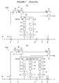
Figure 7(a) and Figure 7(b) illustrate one example of the basic structure of the afore-mentioned conventional pressure type flow rate control apparatus FCS. A major portion of the pressure type flow rate control apparatus FCS comprises acontrol valve 2,pressure detectors orifice 8, flowrate computation circuits rate setting circuit 14, acomputation control circuit 16, a flowrate output circuit 12, and the like. - In
Figure 7(a) and Figure 7(b) , 3 designates an orifice upstream side pipe; 4 designates a valve driving part; 5 designates an orifice downstream side pipe; 9 designates a valve; 15 designates a flow rate conversion circuit; 10, 11, 22, 28 designate amplifiers; 7 designates a temperature detector; 17, 18, 29 designate A/D converters; 19 designates a temperature correction circuit; 20, 30 designate computation circuits; 21 designates a comparison circuit; Qc designates a computation flow rate signal; Qf designates a switching computation flow rate signal; Qe designates a flow rate setting signal; Qo designates a flow rate output signal; Qy designates a flow rate control signal; P1 designates orifice upstream side gas pressure; P2 designates orifice downstream side gas pressure; and k designates a flow rate conversion rate. The afore-mentioned pressure type flow rate control apparatus FCS shown inFigure 7(a) is mainly used either in the case where the ratio P2/P1 of the orifice upstream side gas pressure P1 and the orifice downstream side gas pressure P2 is equal to the critical value of a fluid, or in the case where the ratio P2/P1 is lower than the critical value (that is, when a gas flow is constantly under the critical state). The gas flow rate Qc passing through theorifice 8 is given by Qc=KP1 (where K is a proportionality constant). - The afore-mentioned pressure type flow rate control apparatus FCS shown in
Figure 7(b) is mainly used for the flow rate control of gases that will be in the flow condition in both the critical and non-critical states. The flow rate of a gas passing through an orifice is given, in this case, by Qc= KP2 m (P1-P2)n (where K is a proportionality constant, m and n are constants). - With the afore-mentioned pressure type flow rate control apparatus in
Figure 7(a) and Figure 7(b) , the setting value of the flow rate is given by a voltage value as Qe, the flow rate setting signal. For example, suppose that the pressure control range 0∼3 (kgf/cm2 abs) of the upstream side pressure P1 is expressed by thevoltage range 0∼5V, then Qe=5V (full scale value) becomes equivalent to the flow rate Qc=KP1 at the pressure P1 of 3 (kgf/cm2 abs). For instance, when the conversion rate k of the flowrate conversion circuit 15 is set at 1, a switching computation flow rate signal Qf (Qf=kQc) becomes 5V if the flow rate setting signal Qe=5V is inputted; thus, acontrol valve 2 is operated for opening and closing until the upstream side pressure P1 becomes 3 (kgf/cm2 abs) in order to allow the gas of flow rate Qc=KP1, corresponding to P1=3 (kgf/cm2 abs), to flow through theorifice 8. - In the case where the pressure range to control is switched to 0∼2 (kgf/cm2 abs), and the pressure range is expressed by a flow rate setting signal Qe of 0∼5(V) (that is, when a full scale value 5V gives 2 (kgf/cm2 abs)), the afore-mentioned flow rate conversion rate k is set at 2/3. As a result, if a flow rate setting signal Qe=5(V) is inputted, the switching computation flow rate signal Qf becomes Qf=5x2/3(V) because of the relationship Qf=kQc. And thus, the
control valve 2 is operated for opening and closing until the upstream side pressure P1 becomes 3x2/3=2 (kgf/cm2 abs). - In other words, the full scale flow rate is converted so that Qe=5V expresses a flow rate Qc=KP1 equivalent to P1=2 (kgf/cm2 abs). Under a critical condition, the flow rate Qc of a gas passing through the
orifice 8 is given by the afore-mentioned equation Qc=KP1. However, when the type of gas whose flow rate is to be controlled changes, then the afore-mentioned proportionality constant K also changes if thesame orifice 8 is in use. - It is also same, in principle, with the afore-mentioned pressure type flow rate control apparatus in
Figure 7(b) . The flow rate Qc of a gas passing through theorifice 8 is given by Qc=KP2m (P1-P2)n (where K is a proportionality constant, and m and n are constants). When the type of gas changes, the afore-mentioned proportionality constant K also changes. - [Patent Document 1] TOKU-KAI-HEI
No. 8-338546 - [Patent Document 2] TOKU-KAI
No. 2000-66732 - [Patent Document 3] TOKU-KAI
No. 2000-322130 - [Patent Document 4] TOKU-KAI
No. 2003-195948 - [Patent Document 5] TOKU-KAI
No. 2004-199109 - With a pressure type flow rate control apparatus, especially with an apparatus that employs the method with which computation control is performed as a flow rate Qc=KP1 under the critical state as shown in
Figure 7(a) , the flow rate control range becomes gradually narrower as the orifice secondary side pressure P2 (that is, a chamber and the like to which a gas is supplied) rises. The reason for this is that because the orifice primary side pressure P1 is controlled at a certain pressure value complying with a flow rate setting value, it is inevitable that the correction range of the orifice primary side pressure P1, that is, the control range of a flow rate Qc by means of P1, becomes narrower as the orifice secondary side pressure P2 rises under the conditions in which P2/P1 satisfies the critical expansion conditions. - The flow state of a fluid falling outside the afore-mentioned critical state makes the accuracy of a flow rate control substantially reduced. As a result, unevenness in quality is caused with semiconductor products. In other words, with a pressure type flow rate control apparatus, wherein the flow rate control of a fluid is conducted under a critical state, the possible range available to achieve flow rate control is substantially narrowed in comparison with the possible range available for a conventional thermal type mass flow rate control apparatus or so-called differential pressure type flow rate control apparatus. As a result, manufacturing costs of semiconductor manufacturing facilities, and the like, go up for the reason that two pressure type flow rate control apparatuses having different flow rate control ranges are required.
- The present invention solves the afore-mentioned problems encountered with a conventional flow rate control apparatus, that is, (a) the difficulty in reducing manufacturing costs of a flow rate control apparatus because it becomes necessary that a plurality of flow rate control apparatuses, having different flow rate ranges, are installed in parallel to secure a prescribed control accuracy in the case where a wide flow rate control range is required and thus are used in the manner of switching them, and solves (b) another problem wherein the pressure type flow rate control apparatus, which is basically used for a flow rate control under a critical condition, encounters a flow rate control range that is gradually reduced in view of the pressure rise on the orifice secondary side, which would ordinarily require a plurality of flow rate control apparatuses having different flow rate ranges to be employed to deal with the matter. It is a primary object of the present invention, therefore, to provide a flow rate range variable type flow rate control apparatus, which makes it possible that a highly accurate flow rate control of a fluid is achieved over a wide flow rate control range using only one set of a flow rate control apparatus by means of switching and controlling fluid passages inside the flow rate control apparatus.
- To overcome difficulties with the afore-mentioned flow rate control apparatuses, the present invention as claimed in
Claim 1 is basically constituted so that a flow rate is controlled by means of switching fluid for flowing in a large flow quantity range and fluid for flowing in a small flow quantity range in a manner so that fluid passages connected to a flow rate detection part of the flow rate control apparatus are installed at least for small flow quantity and large flow quantity. With this feature, the first embodiment of the present invention makes fluid flowing in the small flow quantity range flow to the flow detection part through the afore-mentioned fluid passage for small flow quantity, switches the detection level of the flow rate control part to a detection level suitable for the detection of fluid flowing in the small flow rate range and also makes fluid flowing in the large flow quantity range flow to the flow detection part through the afore-mentioned fluid passage for large flow quantity, and switches the detection level suitable for the detection of fluid flowing in the large flow quantity range. - Also, to overcome difficulties with the afore-mentioned invention, the present invention as claimed in
Claim 2 is basically constituted with a pressure type flow rate control apparatus wherein a flow rate of fluid passing through anorifice 8 is computed as Qc=KP1 (where K is a proportionality constant), or as Qc=KP2 m (P1-P2)n (where K is a proportionality constant, m and n constants), by using an orifice upstream side pressure P1 and/or an orifice downstream side pressure P2, and a fluid passage between the downstream side of a control valve and a fluid supply pipe of the pressure type flow rate control apparatus is made to be more than at least 2 fluid passages in parallel, wherein orifices having different flow rate characteristics are provided with the afore-mentioned fluid passages arranged in parallel. In accordance with the second embodiment, the afore-mentioned fluid flowing in the small flow quantity range is made to flow to one orifice for the flow control of the fluid flowing in the small flow quantity range, and the fluid flowing in the large flow quantity range is made to flow to the other orifice for the flow control of the fluid flowing in the large flow quantity range. - The present invention, as claimed in
Claim 3 according toClaim 2, is constituted so that the number of fluid passages arranged in parallel are made to be 2, and there are two orifices provided, one for large flow quantity and the other for small flow quantity, and thus the control range of a fluid's flow rate is switched either to the small flow quantity range or to the large flow quantity range by means of operating a switching valve installed on the fluid passage of the orifice for large flow quantity. - The present invention, as claimed in
Claim 4 according toClaim 2, is constituted so that 3 different orifices are provided including an orifice for a large flow quantity, an orifice for a medium flow quantity and an orifice for a small flow quantity, and a No.1 switching valve, a No.2 switching valve and the orifice for large flow quantity are provided on one fluid passage in series, while the orifice for small flow quantity and the orifice for medium flow quantity are provided on the other fluid passage, and furthermore, the passage for communication between the afore-mentioned 2 switching valves and the passage for communication between the orifice for small flow quantity and the orifice for medium flow quantity are made to be in communication with each other. - The present invention, as claimed in
Claim 5 according toClaim 2, is made so that fluid flowing through an orifice of a pressure type flow rate control apparatus is made to be a fluid under a critical condition. - Furthermore, to overcome difficulties with the afore-mentioned invention, the present invention, as claimed in
Claim 6, is basically constituted so that a thermal type mass flow rate control apparatus comprises a flow rate control valve; a laminar flow element device part; a flow rate sensor part; and the like, wherein temperature changes in proportion to a mass flow rate of a fluid are detected at the flow rate sensor part, and fluid with a certain set flow rate is made to flow out by means of opening/closing a flow rate control valve based on the detected temperature; a fluid passage to the flow rate control valve is made to be more than at least 2 fluid passages arranged in parallel, wherein each of the afore-mentioned parallel passages are provided with both laminar flow elements with different coarseness and flow rate sensors, wherein the afore-mentioned fluid in flowing the small flow quantity range is made to flow to one laminar flow element for flow rate control of fluid flowing in the small flow quantity range, while the afore-mentioned fluid flowing in the large flow quantity range is made to flow to the other laminar flow element for flow rate control of fluid flowing in the large flow quantity range. - The present invention as claimed in
Claim 7 according toClaim 6 is constituted so that the number of fluid passages in parallel are made to be 2, and the two laminar flow elements are made to be a coarse laminar flow element for large flow quantity and a fine laminar flow element for small flow quantity, and the control range of fluid flow rate is switched either to the small flow quantity range or to the large flow quantity range by means of operating switching valves respectively provided on both fluid passages. - The present invention is constituted so that flow rate is controlled in a manner wherein flow rate control is performed by appropriately combining an
orifice 8c for a large flow quantity, anorifice 8a for a small flow quantity (or anorifice 8c for a large flow quantity, anorifice 8b for a medium flow quantity and anorifice 8a for a small flow quantity), thus making it possible that highly accurate flow rate control may be achieved over a wide flow rate range with an error of less than 1% of the set point. Also, the present invention makes operation of flow rate control simple because a flow rate control range can be automatically selected by operating a switching valve. Furthermore, the present invention can be applied to flow rate control of various kinds of fluid supply facilities because of ease of change of the type of gases supplied by making use of a flow factor F.F. in the case wherein flow rate control of fluid is basically under a critical condition. -
-
Figure 1 is a block diagram of a flow rate range variable type flow rate control apparatus according to theembodiment 1. -
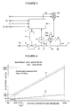
Figure 2 is a chart showing flow rate characteristics of a flow rate control apparatus shown inFigure 1 . -
Figure 3 is a block diagram of a flow rate range variable type flow rate control apparatus according to theembodiment 2. -
Figure 4 is a chart showing flow rate characteristics of a flow rate control apparatus shown inFigure 3 . -
Figure 5 graphically shows flow rate control characteristics of a pressure type flow rate control apparatus FCS outside the range of a critical condition. -
Figure 6 is a block diagram of a flow rate range variable type flow rate control apparatus according to theembodiment 3. -
Figure 7 is an explanatory drawing to show the basic structure of a conventional pressure type flow rate control apparatus. - FCS pressure type flow rate control apparatus
MFC thermal type mass flow rate control apparatus - 1 control part
- 2 control valve
- 3 orifice primary side pipe
- 4 driving part
- 5 fluid supply pipe
- 6 pressure sensor
- 8a orifice for a small flow quantity
- 8b orifice for a medium flow quantity
- 8c orifice for a large flow quantity
- 32 No.1 switching electro-magnetic valve
- 33 No.2 switching electro-magnetic valve
- 34 No.1 switching valve
- 34a valve driving part
- 34b proximity sensor
- 35 No.2 switching valve
- 35a valve driving part
- 35b proximity sensor
- 36 control part
- 36a bridge circuit
- 37 flow rate control valve
- 38, 38a, 38b laminar flow element bypasses
- 39 flow rate sensor part
- 40a, 40b fluid passages
- 41, 42 switching valves
- Referring to the drawings, embodiments of the present invention are described as follows.
-
Figure 1 is a block diagram of a flow rate range variable type flow rate control apparatus according to one embodiment of the present invention. InFigure 1, 1 designates a control part, 2 designates a control valve, 3 designates an orifice upstream side (primary side) pipe, 4 designates a valve driving part, 5 designates a fluid supply pipe, 6 designates a pressure sensor, 8a designates an orifice for a small flow quantity, 8b designates an orifice for a medium flow quantity, 8c designates an orifice for a large flow quantity, 32, 33 designate switching electro-magnetic valves, and 34, 35 designate switching valves. Thecontrol part 1, thecontrol valve 2, thevalve driving part 4, thepressure sensor 6, and the like, of the afore-mentioned pressure type flow rate control apparatus have been disclosed. With respect to the control part, there are provided flow rate input/output signals (i.e., an input signal of a set flow rate, an output signal of a controlled flow rate · DC 0-5V), terminals Qe, Qo, a power supply terminal (±DC 15V) E, and input terminals SL, SM, Ss for providing a controlled flow rate switching command signal. The afore-mentioned switching electro-magnetic valves control part 1 so that switching electro-magnetic valves valve driving parts valves valves proximity switches valve driving parts control part 1. With present embodiments of the invention, for each switchingvalve -
Pipes Figure 1 , form bypass passages fororifices orifice 8a for small flow quantity that flows mainly throughpipes orifice 8b for medium flow quantity throughpipes orifice 8b for medium flow quantity that flows out into thefluid supply pipe 5. Furthermore, when the flow rate to be controlled is in the large flow quantity range area, fluid flows out to theorifice 8c for large flow quantity throughpipe 5a, and the flow rate of fluid is controlled mainly byorifice 8c for large flow quantity that flows in thefluid supply pipe 5. - More specifically, in the case that the maximum flow rate to be controlled is, for example, 2000 SCCM, an orifice for the maximum flow rate of 20 SCCM is employed as the
orifice 8a for small flow quantity, an orifice for the maximum flow rate of 200 SCCM is employed as theorifice 8b for medium flow quantity, and an orifice for the maximum flow quantity of 1780 SCCM is employed as theorifice 8c for large flow quantity, respectively. Namely, in the case that flow rate is controlled for a small flow quantity less than 20 SCCM, the switching signal Ss is inputted to the control part, the driving gas Gc is sent to the NO.2switching valve 35 by releasing NO.2 electro-magnetic switching valve 33, and the NO.2switching valve 35 is released (while the NO.1switching valve 34 is maintained in a state of closing). As a result, fluid flows topipe 5 throughpipe 3,orifice 8a for small flow quantity,pipe 5b,valve 35,orifice 8c for large flow quantity,pipe 5c andpipe 5d,orifice 8b for medium flow quantity, andpipe 5f, and thus the flow rate QL of the fluid being controlled as Q=KLP1 (where KL is a constant specific to theorifice 8a for small flow quantity). Also, the flow rate characteristics of the apparatus ofFigure 1 , in this case, are shown by curve A inFigure 2 . As shown, flow rate control can be performed accurately with an error of less than ± 1 % set point over the flow rate range of 2∼20 SCCM. - In the case wherein the flow rate to be controlled is 200 SCCM (i.e., for approximately medium flow quantity), the No.1
switching valve 34 is switched to the state of opening (i.e., opened) and the No.2switching valve 35 is switched to the state of closing (i.e., closed), and fluid is made to flow toorifice 8b for medium flow quantity throughpipe 3,pipe 5a,valve 34,pipe 5b andpipe 3 again, and throughorifice 8a for small flow quantity. Thus, in this case, the flow rate QM of the fluid being controlled as Q=KMP1 (where KM is a constant specific to theorifice 8b for medium flow quantity). The flow rate characteristics in this case are shown by curve B shown inFigure 2 . As shown, flow rate control can be performed accurately with an error of less than ±1% of the set point over the flow rate range of 20∼200 SCCM. - In addition, in the case wherein the flow rate to be controlled is 2000 SCCM (i.e., the maximum flow rate), both switching
valves magnetic valves pipe 5 throughpipe 3,pipe 5a,valve 34,valve 35, theorifice 8c for large flow quantity,pipe 5c and theorifice 8a for small flow quantity, theorifice 8b for medium flow quantity, andpipe 5f. In this case, the flow rate of the fluid is controlled mainly byorifice 8c for large flow quantity as a flow rate QM=KMP1 (where KM is a constant specific to anorifice 8c for large flow quantity). However, strictly speaking, the flow rate ofpipe 5 is controlled as the sum of the flow rate QM=KMP1 passing throughorifice 8b for medium flow quantity and the flow rate QL=KLP1 passing throughorifice 8c for large flow quantity. Also, in this case, flow rate characteristics are shown by curve C shown inFigure 2 . As shown, the flow rate QL can be controlled accurately with an error of less than ± 1% of the set point over the flow rate range of 200∼2000 SCCM. -
Figure 3 shows another embodiment of the present invention, wherein flow rate control is appropriately performed by employing anorifice 8a for small flow quantity and anorifice 8c for large flow quantity. For example, in the case that flow rate control for a maximum flow rate of 2000 SCCM is performed, the apparatus is constructed so that a flow rate up to 200 SCCM is controlled by theorifice 8a for small flow quantity and a flow rate up to 2000 SCCM is controlled by theorifice 8c for large flow quantity. Specifically, in the case that a flow rate of up to 200 SCCM is controlled, the switchingvalve 34 is maintained in a state of closing (i.e., closed), and the flow rate Qs of a fluid passing through theorifice 8a for small flow quantity is controlled as Qs=KsP1 (where Ks is a constant specific to theorifice 8a). By using theorifice 8a for small flow quantity, the flow rate can be controlled accurately with an error of less than ± 1 % set point over the flow rate range of 20 SCCM∼2000 SCCM. Curve D inFigure 4 shows the flow rate control characteristics for the embodiment shown inFigure 3 . In the case that the pressure inpipe 5 on the orifice downstream side is less than 100 Torr, it has been verified that the error can be reduced to less than ± 1 % of the set point with a flow rate of 20 SCCM. - In accordance with the afore-mentioned flow rate control apparatus shown in
Figure 3 , if the orifice downstream pressure exceeds 100 Torr, or if the flow rate Qs of the fluid is found to be less than 20 SCCM although the orifice downstream side pressure is less than 100 Torr, then it becomes difficult to maintain the flow rate control error to be less than ±1% of the set point. Accordingly, in such a case, the flow rate range of less than 20 SCCM is controlled in the manner of a so-called pulse control as shown inFigure 4 . Pulse control mentioned herein is a control method wherein fluid is made to flow intopipe 3 in a pulse form by performing the opening and closing of acontrol valve 2 on the orifice upstream side by using pulse signals so that the flow rate of a fluid passing through theorifice 8a for small flow quantity can be controlled with comparatively high accuracy by means of adjusting the number of pulse signals opening and closing thecontrol valve 2. On the other hand, to control the flow rate of fluid of less than 2000 SCCM, the switchingvalve 34 is released through the mediation of the switching electro-magnetic valve 32. Thus, the fluid is made to flow topipe 5 throughpipe 5a, switchingvalve 34,orifice 8c for large flow quantity,orifice 8a for small flow quantity, andpipe 5g. In particular, the flow rate of fluid flowing intopipe 5 is the sum of the flow rate QC=KCP1 passing throughorifice 8c for large flow quantity (where Kc is a constant specific to orifice 8c for large flow quantity) and the flow rate Qs=KsP1 passing throughorifice 8a for small flow quantity (where Ks is a constant specific toorifice 8a for small flow quantity). The curvature of flow rate characteristics is as shown by curve E inFigure 4 . - As described above, in accordance with the first two embodiments of the present invention, the accuracy of flow rate control with an error of less than ± 1% set point becomes possible over a wide flow rate control range of, for example, 2 SCCM∼2000 SCCM, by means of appropriately combining
orifice 8c for large flow quantity andorifice 8a for small flow quantity (ororifice 8c for large flow quantity,orifice 8b for medium flow quantity andorifice 8a for small flow quantity). A swift switching operation is required, however, to change the flow rate of a gas when the flow rate control is performed usingorifice 8a for small flow quantity. In such a case, with the present invention, the pressure drop time for a pipe on the orifice secondary side can be easily shortened by installing bypass passages (5a, 34, 8c, 5c) in parallel with the flow passage in whichorifice 8a is disposed, and releasing the bypass passages. - Furthermore, in accordance with the
embodiment 1 and theembodiment 2 of the present invention described above, because the apparatus is constructed so that the flow rate control of fluid is performed under a critical condition, the computed flow rate Q can be converted to the flow rate of a gas in use by making use of a so-called flow factor F.F. even when a type of gas flowing is changed. Thus, it is possible that excellent properties of the pressure type flow rate control apparatus may be fully utilized. However, accuracy of flow rate control in a state outside of the critical condition of the fluid, wherein a pressure type flow rate control apparatus used in theembodiment 1 and theembodiment 2 is shown inFigure 5 wherein an orifice secondary side pressure P2 is made a parameter. For example, as shown by curve F, in the case of P2=100 Torr, the error exceeds -1% F.S. at a point wherein the flow rate to be controlled reaches approximately 5% of a rated set flow rate. As a result, as shown by curve D (20 SCCM∼200 SCCM withorifice 8a for small flow quantity) inFigure 4 , the flow rate control can be performed surely and accurately with an error of less than ± 1 % of the set point between 20 SCCM∼200 SCCM. However, when the flow rate to be controlled is less than 20 SCCM, it becomes difficult in practice to lower the error of less than 1% F.S. to the point of theapproximate flow rate 5% (200 SCCMx5%=10 SCCM) of the set flow rate because when the flow rate to be controlled becomes less than 20 SCCM, the apparatus falls out of a critical condition at a time wherein the orifice secondary side pressure P2 is 100 Torr. Accordingly, as shown inFigure 4 , in the case of a small flow quantity area (10 SCCM∼20 SCCM) of 5%~10% of the set flow rate, a pulse control method can be employed. (Of course, there is no need to employ the method when an error of less than 0.1 % F.S. (when a full scale of the orifice for large flow quantity is used as the standard) can be maintained.) -
Figure 6 shows theembodiment 3 of the present invention wherein a so-called thermal type mass flow rate control apparatus MFC is employed in a flow rate control apparatus. As shown inFigure 6 , the thermal type mass flow rate control apparatus comprises acontrol part 36, a flowrate control valve 37, a laminar flowelement bypass part 38, a flow rate sensor part 39, a switching valve 41, 42, and the like. Temperature changes in proportion to a mass flow rate of a fluid are detected with a flow rate sensor part 39, and fluid of a certain set flow rate is made to flow out by controlling the flowrate control valve 37 for opening and closing based on the detected temperature. A thermal type mass flow rate control apparatus MFC itself has been disclosed. Therefore, a detail description of such is omitted here. - In
Figure 6 , 36a designates a bridge circuit, 36b designates an amplification circuit, 36c designates a correction circuit, 36d designates a comparison circuit, 36e designates a valve driving circuit and 36f designates an actuator. In accordance with this embodiment of the present invention, twopassages flow bypass part 38, and switching valves 41, 42 are provided on thepassages laminar element 38a is provided on onefluid passage 40a of the bypass passage, which is used for flow rate control of a fluid with a medium flow quantity, while the coarserlaminar element 38b is provided on theother fluid passage 40b of the bypass passage, which is used for flow rate control of fluid with a large flow quantity. Specifically, the switching valve 41 and the switching valve 42 are made to open when controlling flow rate of fluid with a large flow quantity. On the other hand, the switching valve 42 and the switching valve 41 are made to close in order to control flow rate of fluid with a small flow quantity, and the amplification level of theamplification circuit 36b of thecontrol part 36 is switched to a level suitable for detecting a small flow quantity. Furthermore, the switching valve 41 is made to close and the switching valve 42 is made to open in order to control the flow rate of fluid with a medium flow quantity, and the amplification level and the like of the afore-mentionedamplification circuit 36b is switched to a level suitable for detecting medium flow quantity. Accordingly, a highly accurate flow rate control becomes possible over three flow rate ranges of large, medium and small flow quantities by using one set of thermal type mass flow rate control apparatus MFC wherein the afore-mentioned switching valves 41, 42 are switched, and the amplification level of thecontrol part 36 and the like are also switched. - The present invention can be applied to fluid supplying facilities for various kinds of fluid used with industries such as semiconductor manufacturing, chemical goods manufacturing, pharmaceutical products manufacturing, foods processing, and the like.
Claims (7)
- A flow rate range variable type flow rate control apparatus characterized by that it is so constituted that a flow rate is controlled by means of switching a fluid in a large flow quantity range and a fluid in a small flow quantity range in the manner that fluid passages to a flow rate detection part of the flow rate control apparatus are installed at least for a small flow quantity and a large flow quantity, making a fluid in a small flow quantity range flow to a flow detection part through the afore-mentioned fluid passage for a small flow quantity, to switch the detection level of a flow rate control part to the detection level suitable for the detection of a small flow quantity range and also making a fluid in a large flow quantity range flow to a flow detection part through the afore-mentioned fluid passage for a large flow quantity, to switch the detection level suitable for the detection of a large flow quantity range.
- A flow rate range variable type flow rate control apparatus characterized by that it is so constituted that with a pressure type flow rate control apparatus wherein a flow rate of a fluid passing through an orifice 8 is computed as Qc=KP1 (where K is a proportionality constant) or as Qc=KP2 m (P1-P2)n (where K is a proportionality constant, m and n constants) by using an orifice upstream side pressure P1 and/or an orifice downstream side pressure P2, a fluid passage between the downstream side of a control valve and a fluid supply pipe of said pressure type flow rate control apparatus are made to be more than at least 2 fluid passages in parallel, orifices having different flow rate characteristics are provided with the afore-mentioned fluid passages arranged in parallel, the afore-mentioned fluid in a small flow quantity area is made to flow to one orifice for the flow control of the fluid in a small flow quantity range, while the fluid in a large flow quantity range is made to flow to the other one for the flow control of the fluid in a large flow quantity range.
- A flow rate range variable type flow rate control apparatus as claimed in Claim 2 wherein it is so constituted that the number of fluid passages arranged in parallel are made to be 2, and two orifices, one for a large flow quantity and the other for a small flow quantity are provided, and thus the control range of a fluid's flow rate is switched either to a small flow quantity range or to a large flow quantity range by means of operating a switching valve installed on the fluid passage of the orifice for a large flow quantity.
- A flow rate range variable type flow rate control apparatus as claimed in Claim 2 wherein it is so constituted that 3 different orifices, an orifice for a large flow quantity, an orifice for a medium flow quantity and an orifice for a small flow quantity, are made, and No.1 switching valve, No.2 switching valve and an orifice for a large flow quantity are provided on one fluid passage in series, while an orifice for a small flow quantity and an orifice for a medium flow quantity are provided on the other fluid passage, and furthermore, the passage for communication with between the afore-mentioned 2 switching valves and the passage for communication between an orifice for a small flow quantity and an orifice for a medium flow quantity are made to be in communication each other.
- A flow rate range variable type flow rate control apparatus as claimed in Claim 2 wherein it is so made that a fluid flowing through an orifice of a pressure type flow rate control apparatus is made to be a fluid under a critical condition.
- A flow rate range variable type flow rate control apparatus characterized by that it is so constituted that with a thermal type mass flow rate control apparatus comprising a flow rate control valve, a laminar flow element device part, a flow rate sensor part, and the like, wherein temperature changes in proportion to a mass flow rate of a fluid are detected at the flow rate sensor part, and a fluid with a certain set flow rate is made to flow out by means of opening/closing a flow rate control valve based on said detected temperature, a fluid passage to a flow rate control valve is made to be more than at least 2 fluid passages arranged in parallel, both laminar flow elements with different coarseness and flow rate sensors are provided with the afore-mentioned fluid passages in parallel, the afore-mentioned fluid in a small flow quantity range is made to flow to one laminar flow element for a flow rate control of a fluid in a small flow quantity range while the afore-mentioned fluid in a large flow quantity range is made to flow to the other laminar flow element for a flow rate control of a fluid in a large flow quantity range.
- A flow rate range variable type flow rate control apparatus as claimed in Claim 6, wherein it is so constituted that the number of fluid passages in parallel are made to be 2, two laminar flow elements are made to be a coarse laminar flow element for a large flow quantity and a fine laminar flow element for a small flow quantity, and the control range of a fluid flow rate is switched either to a small flow quantity range or to a large flow quantity range by means of operating switching valves respectively provided on both fluid passages.
Applications Claiming Priority (2)
| Application Number | Priority Date | Filing Date | Title |
|---|---|---|---|
| JP2005185845A JP4856905B2 (en) | 2005-06-27 | 2005-06-27 | Flow rate variable type flow control device |
| PCT/JP2006/312952 WO2007001041A1 (en) | 2005-06-27 | 2006-06-22 | Variable flow range type flow control device |
Publications (1)
| Publication Number | Publication Date |
|---|---|
| EP1901154A1 true EP1901154A1 (en) | 2008-03-19 |
Family
ID=37595286
Family Applications (1)
| Application Number | Title | Priority Date | Filing Date |
|---|---|---|---|
| EP06767569A Withdrawn EP1901154A1 (en) | 2005-06-27 | 2006-06-22 | Variable flow range type flow control device |
Country Status (7)
| Country | Link |
|---|---|
| US (3) | US8418714B2 (en) |
| EP (1) | EP1901154A1 (en) |
| JP (1) | JP4856905B2 (en) |
| KR (1) | KR20070110499A (en) |
| CN (1) | CN101208641B (en) |
| TW (1) | TW200712814A (en) |
| WO (1) | WO2007001041A1 (en) |
Cited By (2)
| Publication number | Priority date | Publication date | Assignee | Title |
|---|---|---|---|---|
| EP2216631A1 (en) * | 2009-02-05 | 2010-08-11 | Surpass Industry Co., Ltd. | Flowmeter and flow-rate controller |
| US9127796B2 (en) | 2008-12-26 | 2015-09-08 | Fujikin Incorporated | Gasket type orifice and pressure type flow rate control apparatus for which the orifice is employed |
Families Citing this family (62)
| Publication number | Priority date | Publication date | Assignee | Title |
|---|---|---|---|---|
| US9921089B2 (en) * | 2005-06-27 | 2018-03-20 | Fujikin Incorporated | Flow rate range variable type flow rate control apparatus |
| JP5041427B2 (en) | 2008-03-19 | 2012-10-03 | Ckd株式会社 | Flow control device |
| KR101162546B1 (en) * | 2008-05-21 | 2012-07-05 | 가부시키가이샤 후지킨 | Discontinuous switching flow control method of fluid using pressure type flow controller |
| JP5213583B2 (en) * | 2008-08-18 | 2013-06-19 | アドバンス電気工業株式会社 | Flow measuring device |
| JP5213582B2 (en) * | 2008-08-18 | 2013-06-19 | アドバンス電気工業株式会社 | Flow measuring device |
| JP5357478B2 (en) * | 2008-09-24 | 2013-12-04 | アドバンス電気工業株式会社 | Differential pressure type flow measuring device |
| US7891228B2 (en) * | 2008-11-18 | 2011-02-22 | Mks Instruments, Inc. | Dual-mode mass flow verification and mass flow delivery system and method |
| JP5216632B2 (en) * | 2009-03-03 | 2013-06-19 | 東京エレクトロン株式会社 | Fluid control device |
| JP5508875B2 (en) | 2010-01-26 | 2014-06-04 | 株式会社フジキン | Fluid controller and flow control device |
| WO2011101934A1 (en) | 2010-02-22 | 2011-08-25 | 株式会社フジキン | Mixture gas supply device |
| JP5562712B2 (en) * | 2010-04-30 | 2014-07-30 | 東京エレクトロン株式会社 | Gas supply equipment for semiconductor manufacturing equipment |
| JP5703032B2 (en) * | 2011-01-06 | 2015-04-15 | 株式会社フジキン | Flow rate measuring method of flow controller for gas supply device |
| ES2522166T3 (en) * | 2011-01-14 | 2014-11-13 | Grundfos Management A/S | System and method to control the pressure in a network |
| JP5605969B2 (en) | 2011-05-10 | 2014-10-15 | 株式会社フジキン | Pressure type flow rate control device with flow rate monitor, fluid supply system abnormality detection method using the same, and treatment method for monitor flow rate abnormality |
| JP5755958B2 (en) | 2011-07-08 | 2015-07-29 | 株式会社フジキン | Raw material gas supply equipment for semiconductor manufacturing equipment |
| JP5647083B2 (en) | 2011-09-06 | 2014-12-24 | 株式会社フジキン | Raw material vaporization supply device with raw material concentration detection mechanism |
| JP2013057278A (en) * | 2011-09-07 | 2013-03-28 | Mitsubishi Heavy Ind Ltd | Gas turbine |
| TWI458843B (en) * | 2011-10-06 | 2014-11-01 | Ind Tech Res Inst | Evaporation apparatus and method of forminf organic film |
| US9846074B2 (en) * | 2012-01-20 | 2017-12-19 | Mks Instruments, Inc. | System for and method of monitoring flow through mass flow controllers in real time |
| US9557744B2 (en) | 2012-01-20 | 2017-01-31 | Mks Instruments, Inc. | System for and method of monitoring flow through mass flow controllers in real time |
| US9471066B2 (en) | 2012-01-20 | 2016-10-18 | Mks Instruments, Inc. | System for and method of providing pressure insensitive self verifying mass flow controller |
| JP5754853B2 (en) * | 2012-01-30 | 2015-07-29 | 株式会社フジキン | Gas shunt supply device for semiconductor manufacturing equipment |
| US20130240045A1 (en) * | 2012-03-15 | 2013-09-19 | Xiufeng Pang | Method for Determining a Fluid Flow Rate With a Fluid Control Valve |
| JP5665793B2 (en) * | 2012-04-26 | 2015-02-04 | 株式会社フジキン | Variable orifice type pressure control flow controller |
| JP5665794B2 (en) * | 2012-04-27 | 2015-02-04 | 株式会社フジキン | Gas shunt supply device for semiconductor manufacturing equipment |
| JP5947659B2 (en) * | 2012-08-06 | 2016-07-06 | 株式会社堀場エステック | Flow control device |
| DE102012017207A1 (en) * | 2012-08-31 | 2014-03-06 | Robert Bosch Gmbh | Method for controlling a hydraulic valve arrangement and hydraulic valve arrangement |
| US10031005B2 (en) | 2012-09-25 | 2018-07-24 | Mks Instruments, Inc. | Method and apparatus for self verification of pressure-based mass flow controllers |
| CN102968132A (en) * | 2012-11-28 | 2013-03-13 | 重庆赛联自动化工程技术有限公司 | High-precision large-flow gas control method for bottom blowing system of revolving furnace |
| US9454158B2 (en) | 2013-03-15 | 2016-09-27 | Bhushan Somani | Real time diagnostics for flow controller systems and methods |
| JP5847106B2 (en) * | 2013-03-25 | 2016-01-20 | 株式会社フジキン | Pressure flow control device with flow monitor. |
| JP5893592B2 (en) * | 2013-08-23 | 2016-03-23 | 東京エレクトロン株式会社 | Liquid processing equipment |
| JP5797246B2 (en) * | 2013-10-28 | 2015-10-21 | 株式会社フジキン | Flow meter and flow control device including the same |
| JP6158111B2 (en) * | 2014-02-12 | 2017-07-05 | 東京エレクトロン株式会社 | Gas supply method and semiconductor manufacturing apparatus |
| CN104215406B (en) * | 2014-09-12 | 2017-04-05 | 天津博益气动股份有限公司 | Wide-range flow-type leak detector and its detection method |
| TW201634738A (en) * | 2015-01-22 | 2016-10-01 | 應用材料股份有限公司 | Improved injector for spatially separated atomic layer deposition chamber |
| CN106257370B (en) * | 2015-06-19 | 2019-07-02 | 株式会社Posco | Bias current control device and bias current control method |
| CN108351240B (en) | 2015-08-31 | 2020-10-20 | Mks 仪器公司 | Method and apparatus for pressure-based flow control under noncritical flow conditions |
| JP6775288B2 (en) * | 2015-10-08 | 2020-10-28 | 株式会社堀場エステック | Fluid control valve and its control program |
| US10665430B2 (en) * | 2016-07-11 | 2020-05-26 | Tokyo Electron Limited | Gas supply system, substrate processing system and gas supply method |
| JP6786096B2 (en) * | 2016-07-28 | 2020-11-18 | 株式会社フジキン | Pressure type flow control device |
| US20180046206A1 (en) * | 2016-08-13 | 2018-02-15 | Applied Materials, Inc. | Method and apparatus for controlling gas flow to a process chamber |
| US10364136B2 (en) * | 2016-09-26 | 2019-07-30 | Gate Cfv Solutions, Inc. | Valve device |
| JP6996289B2 (en) * | 2016-12-26 | 2022-01-17 | 株式会社島津製作所 | Valve device |
| US10983538B2 (en) | 2017-02-27 | 2021-04-20 | Flow Devices And Systems Inc. | Systems and methods for flow sensor back pressure adjustment for mass flow controller |
| US10344237B2 (en) * | 2017-04-13 | 2019-07-09 | Welker, Inc. | System and method for odorizing natural gas |
| US11460869B2 (en) | 2017-07-31 | 2022-10-04 | Fujikin Incorporated | Fluid control system and flow rate measurement method |
| JP6960278B2 (en) * | 2017-08-31 | 2021-11-05 | 東京エレクトロン株式会社 | How to inspect the flow measurement system |
| JP7216422B2 (en) * | 2017-09-30 | 2023-02-01 | 株式会社フジキン | fluid supply line |
| KR102314330B1 (en) * | 2017-11-30 | 2021-10-19 | 가부시키가이샤 후지킨 | flow control device |
| JP7190186B2 (en) * | 2017-11-30 | 2022-12-15 | 株式会社フジキン | Self-diagnosis method for flow controller |
| JP7008499B2 (en) * | 2017-12-27 | 2022-01-25 | 株式会社堀場エステック | Calibration data creation device, calibration data creation method, and flow control device |
| US11004711B2 (en) * | 2018-08-17 | 2021-05-11 | Taiwan Semiconductor Manufacturing Co., Ltd. | Automated wafer monitoring |
| RU2682540C9 (en) * | 2018-08-22 | 2019-07-08 | Александр Александрович Калашников | The method of setting the flow measurement channel with a restriction device |
| WO2020136818A1 (en) * | 2018-12-27 | 2020-07-02 | 伸和コントロールズ株式会社 | Valve unit and temperature control device |
| JP7232506B2 (en) * | 2018-12-27 | 2023-03-03 | 株式会社フジキン | flow pressure controller |
| CN109855691B (en) * | 2019-01-14 | 2020-06-09 | 中国计量大学 | Differential laminar flow measuring method and device |
| CN110657849A (en) * | 2019-11-13 | 2020-01-07 | 新疆中元天能油气科技股份有限公司 | Oil gas field flow metering system |
| CN112169584A (en) * | 2020-10-09 | 2021-01-05 | 山东国舜建设集团有限公司 | Device and method for controlling ammonia water flow in denitration system |
| KR20230000975A (en) * | 2021-06-25 | 2023-01-03 | 가부시키가이샤 호리바 에스텍 | Fluid control device, fluid control system, program for fluid control device, and fluid control method |
| CN118511059A (en) * | 2021-08-13 | 2024-08-16 | Tsi有限公司 | Differential pressure liquid flow controller |
| US12366869B2 (en) * | 2023-03-13 | 2025-07-22 | Robertshaw Controls Company | Pressure sensing valve |
Family Cites Families (71)
| Publication number | Priority date | Publication date | Assignee | Title |
|---|---|---|---|---|
| US1938460A (en) | 1933-12-05 | Orifice fitting | ||
| US2229903A (en) * | 1939-02-04 | 1941-01-28 | Arthur L Parker | Metering valve |
| US3081942A (en) * | 1961-09-18 | 1963-03-19 | Ibm | Digital-to-analog control system |
| US3375845A (en) * | 1964-04-21 | 1968-04-02 | Houdaille Industries Inc | Fluid flow device |
| US3411669A (en) | 1966-09-08 | 1968-11-19 | Reynolds Metals Co | Beverage dispenser regulation and the like |
| GB1364841A (en) * | 1971-08-12 | 1974-08-29 | British Oxygen Co Ltd | Fluid mixing |
| US3827457A (en) * | 1973-06-22 | 1974-08-06 | Westinghouse Air Brake Co | Fluid pressure system for converting digital signals to analog signals |
| US3831845A (en) * | 1973-08-17 | 1974-08-27 | Partek Corp Of Houston | Fluid delivery system |
| US3905394A (en) * | 1974-04-12 | 1975-09-16 | Digital Dynamics Inc | Flow control system |
| US3963043A (en) * | 1975-01-02 | 1976-06-15 | Motorola, Inc. | Pressure sensing method and apparatus for gases |
| US3999572A (en) * | 1975-03-24 | 1976-12-28 | The Garrett Corporation | Fluid flow instrumentality |
| JPS534570A (en) * | 1975-12-30 | 1978-01-17 | Mitsui Shipbuilding Eng | Apparatus for measuring flow rate in wide range |
| US4030523A (en) * | 1976-04-19 | 1977-06-21 | The United States Of America As Represented By The Secretary Of The Navy | Digital flow control system |
| US4089007A (en) * | 1976-05-24 | 1978-05-09 | International Business Machines Corporation | Digital flow pressure regulator |
| DE2751743C2 (en) * | 1977-11-19 | 1985-04-18 | Pierburg Luftfahrtgeräte Union GmbH, 4040 Neuss | Method and control device for metering flowing media |
| JPS57122528U (en) * | 1981-01-23 | 1982-07-30 | ||
| DE3130056C2 (en) * | 1981-07-30 | 1983-11-17 | Festo-Maschinenfabrik Gottlieb Stoll, 7300 Esslingen | Control valve arrangement for a pressure medium working cylinder |
| US4478246A (en) * | 1981-08-10 | 1984-10-23 | Donnell Sherrod | Method and apparatus for proportioning of fuel usage by a fluid fueled apparatus |
| US4431020A (en) * | 1981-10-08 | 1984-02-14 | Marotta Scientific Controls, Inc. | Flow-control system having a wide range of flow-rate control |
| US4633911A (en) | 1985-01-18 | 1987-01-06 | Control Specialties Co., Inc. | Orifice plate seal |
| JP2814378B2 (en) * | 1988-06-20 | 1998-10-22 | 忠弘 大見 | Mass flow controller |
| US4979639A (en) * | 1989-05-23 | 1990-12-25 | The Coca-Cola Company | Beverage dispenser control valve and ratio control method therefor |
| JPH0333566A (en) | 1989-06-29 | 1991-02-13 | Hitachi Metals Ltd | Digital valve |
| US5069252A (en) | 1990-12-18 | 1991-12-03 | Daniel Industries, Inc. | Orifice system intermediate interface |
| JPH064139A (en) * | 1992-06-17 | 1994-01-14 | Seiko Epson Corp | Flow controller |
| US5269334A (en) * | 1992-06-22 | 1993-12-14 | New York State Electric & Gas Corporation | Fluid flow control system |
| DE4236460C2 (en) * | 1992-10-29 | 1995-11-23 | Battenfeld Gmbh | Pressure control and / or regulating device for a fluid medium, in particular air or gas |
| US5329965A (en) * | 1993-07-30 | 1994-07-19 | The Perkin-Elmer Corporation | Hybrid valving system for varying fluid flow rate |
| DE4400489C2 (en) * | 1994-01-11 | 1996-03-28 | Filtan Gmbh | Centrifugal separator, device and method |
| JP3818547B2 (en) * | 1994-09-16 | 2006-09-06 | 株式会社堀場エステック | Mass flow controller |
| US5660207A (en) * | 1994-12-29 | 1997-08-26 | Tylan General, Inc. | Flow controller, parts of flow controller, and related method |
| JP3291161B2 (en) * | 1995-06-12 | 2002-06-10 | 株式会社フジキン | Pressure type flow controller |
| CA2183478C (en) * | 1995-08-17 | 2004-02-24 | Stephen A. Carter | Digital gas metering system using tri-stable and bi-stable solenoids |
| JPH09330128A (en) * | 1996-06-13 | 1997-12-22 | Fujitsu Ltd | Mass flow controller |
| DE19627539A1 (en) * | 1996-07-09 | 1998-01-15 | Gaggenau Werke | Method and device for controlling the flame size of gas-operated cooking or baking devices |
| JP3580645B2 (en) | 1996-08-12 | 2004-10-27 | 忠弘 大見 | Pressure type flow controller |
| US5911238A (en) * | 1996-10-04 | 1999-06-15 | Emerson Electric Co. | Thermal mass flowmeter and mass flow controller, flowmetering system and method |
| FR2755522B1 (en) * | 1996-11-05 | 1998-12-18 | Air Liquide | DEVICE FOR REGULATING THE GAS FLOW HAVING SUBSTANTIALLY DIFFERENT MOLAR MASSES |
| JP3586075B2 (en) * | 1997-08-15 | 2004-11-10 | 忠弘 大見 | Pressure type flow controller |
| JPH11125398A (en) | 1997-10-20 | 1999-05-11 | Ckd Corp | Flow restriction mechanism |
| JPH11212653A (en) * | 1998-01-21 | 1999-08-06 | Fujikin Inc | Fluid supply device |
| JPH11265216A (en) * | 1998-03-17 | 1999-09-28 | Omi Tadahiro | Pressure type flow controller |
| JP3971840B2 (en) | 1998-03-17 | 2007-09-05 | 大見 忠弘 | Pressure flow control device |
| JP2000020135A (en) | 1998-06-29 | 2000-01-21 | Ishikawajima Harima Heavy Ind Co Ltd | Flow control device |
| JP3522544B2 (en) * | 1998-08-24 | 2004-04-26 | 忠弘 大見 | Variable fluid type flow controller |
| JP3033566B1 (en) | 1998-10-07 | 2000-04-17 | 日産自動車株式会社 | Transmission control device for automatic transmission |
| DE19914282A1 (en) * | 1999-03-30 | 2000-10-05 | Leybold Vakuum Gmbh | Seal gas valve device |
| EP2028577A2 (en) * | 1999-04-16 | 2009-02-25 | Fujikin Incorporated | Parallel bypass type fluid feeding device, and method and device for controlling fluid variable type pressure system flow rate used for the device |
| JP3387849B2 (en) | 1999-05-10 | 2003-03-17 | 株式会社フジキン | Variable fluid flow control method and device using flow factor |
| JP3554509B2 (en) * | 1999-08-10 | 2004-08-18 | 忠弘 大見 | Flow rate abnormality detection method in pressure flow control device |
| US6314991B1 (en) * | 2000-03-02 | 2001-11-13 | Rajinder S. Gill | Mass flow controller |
| US6539968B1 (en) | 2000-09-20 | 2003-04-01 | Fugasity Corporation | Fluid flow controller and method of operation |
| JP4102564B2 (en) * | 2001-12-28 | 2008-06-18 | 忠弘 大見 | Improved pressure flow controller |
| US6981518B2 (en) * | 2002-03-15 | 2006-01-03 | Cytonome, Inc. | Latching micro-regulator |
| US7552015B2 (en) * | 2002-06-24 | 2009-06-23 | Mks Instruments, Inc. | Apparatus and method for displaying mass flow controller pressure |
| US6712084B2 (en) * | 2002-06-24 | 2004-03-30 | Mks Instruments, Inc. | Apparatus and method for pressure fluctuation insensitive mass flow control |
| US7073392B2 (en) * | 2002-07-19 | 2006-07-11 | Celerity, Inc. | Methods and apparatus for pressure compensation in a mass flow controller |
| JP3910139B2 (en) | 2002-12-16 | 2007-04-25 | 株式会社フジキン | Fluid flow control method using pressure type flow control device |
| US6997202B2 (en) * | 2002-12-17 | 2006-02-14 | Advanced Technology Materials, Inc. | Gas storage and dispensing system for variable conductance dispensing of gas at constant flow rate |
| JP2004243333A (en) | 2003-02-12 | 2004-09-02 | Hitachi Ltd | Welding device and welding method |
| JP2004278614A (en) | 2003-03-14 | 2004-10-07 | Tlv Co Ltd | Wafer type orifice trap |
| KR100517405B1 (en) * | 2003-06-27 | 2005-09-27 | 삼성전자주식회사 | Mass flow controller and Apparatus for supplying a gas having the same |
| KR100418684B1 (en) * | 2003-06-27 | 2004-02-14 | 주식회사 현대교정인증기술원 | Differential pressure type fluid mass flow controller for controlling flow gases used in semiconductor device fabrication |
| JP4204400B2 (en) * | 2003-07-03 | 2009-01-07 | 忠弘 大見 | Differential pressure type flow meter and differential pressure type flow control device |
| US7669590B2 (en) * | 2003-09-25 | 2010-03-02 | Bsh Bosch Und Siemens Hausgeraete Gmbh | Gas cooking surface |
| JP4399227B2 (en) | 2003-10-06 | 2010-01-13 | 株式会社フジキン | Chamber internal pressure control device and internal pressure controlled chamber |
| JP4298476B2 (en) | 2003-11-14 | 2009-07-22 | 株式会社フジキン | Fluid control device |
| JP4184252B2 (en) | 2003-12-18 | 2008-11-19 | シーケーディ株式会社 | Leak valve |
| US7621290B2 (en) * | 2005-04-21 | 2009-11-24 | Mks Instruments, Inc. | Gas delivery method and system including a flow ratio controller using antisymmetric optimal control |
| US7673645B2 (en) * | 2005-04-21 | 2010-03-09 | Mks Instruments, Inc. | Gas delivery method and system including a flow ratio controller using a multiple antisymmetric optimal control arrangement |
| JP4814706B2 (en) * | 2006-06-27 | 2011-11-16 | 株式会社フジキン | Flow ratio variable type fluid supply device |
-
2005
- 2005-06-27 JP JP2005185845A patent/JP4856905B2/en not_active Expired - Lifetime
-
2006
- 2006-06-22 US US11/913,277 patent/US8418714B2/en active Active
- 2006-06-22 KR KR1020077019468A patent/KR20070110499A/en not_active Ceased
- 2006-06-22 EP EP06767569A patent/EP1901154A1/en not_active Withdrawn
- 2006-06-22 CN CN2006800232002A patent/CN101208641B/en active Active
- 2006-06-22 WO PCT/JP2006/312952 patent/WO2007001041A1/en not_active Ceased
- 2006-06-26 TW TW095123000A patent/TW200712814A/en unknown
-
2013
- 2013-02-08 US US13/763,178 patent/US9010369B2/en active Active
-
2015
- 2015-02-19 US US14/626,128 patent/US20150160662A1/en not_active Abandoned
Non-Patent Citations (1)
| Title |
|---|
| See references of WO2007001041A1 * |
Cited By (3)
| Publication number | Priority date | Publication date | Assignee | Title |
|---|---|---|---|---|
| US9127796B2 (en) | 2008-12-26 | 2015-09-08 | Fujikin Incorporated | Gasket type orifice and pressure type flow rate control apparatus for which the orifice is employed |
| EP2216631A1 (en) * | 2009-02-05 | 2010-08-11 | Surpass Industry Co., Ltd. | Flowmeter and flow-rate controller |
| US8205635B2 (en) | 2009-02-05 | 2012-06-26 | Surpass Industry Co., Ltd. | Flowmeter and flow-rate controller |
Also Published As
| Publication number | Publication date |
|---|---|
| JP4856905B2 (en) | 2012-01-18 |
| US9010369B2 (en) | 2015-04-21 |
| JP2007004644A (en) | 2007-01-11 |
| US8418714B2 (en) | 2013-04-16 |
| US20100139775A1 (en) | 2010-06-10 |
| KR20070110499A (en) | 2007-11-19 |
| WO2007001041A1 (en) | 2007-01-04 |
| US20150160662A1 (en) | 2015-06-11 |
| TW200712814A (en) | 2007-04-01 |
| TWI320520B (en) | 2010-02-11 |
| US20130220451A1 (en) | 2013-08-29 |
| CN101208641B (en) | 2012-11-07 |
| CN101208641A (en) | 2008-06-25 |
Similar Documents
| Publication | Publication Date | Title |
|---|---|---|
| US8418714B2 (en) | Flow rate range variable type flow rate control apparatus | |
| US9921089B2 (en) | Flow rate range variable type flow rate control apparatus | |
| US9383758B2 (en) | Flow rate range variable type flow rate control apparatus | |
| JP5175965B2 (en) | Flow rate variable type flow control device | |
| CN108027618B (en) | Pressure type flow rate control device and abnormality detection method thereof | |
| US9169558B2 (en) | Fluid control apparatus | |
| JP4195837B2 (en) | Gas diversion supply apparatus and gas diversion supply method | |
| KR101162546B1 (en) | Discontinuous switching flow control method of fluid using pressure type flow controller | |
| CN105659177B (en) | Pressure flow-rate controller | |
| KR101677971B1 (en) | Gas split-flow supply device for semiconductor production device | |
| KR101632602B1 (en) | Gas separation and supply device for semiconductor manufacturing apparatus | |
| CN105940357A (en) | Pressure type flow control device and method for preventing overshoot at the start of flow control | |
| EP1026566A4 (en) | Versatile flow rate controller | |
| US11561560B2 (en) | Flow controller, valve arrangement and method | |
| KR100593346B1 (en) | Gas flow control device and control method | |
| US12504773B2 (en) | Low bleed fluid control system |
Legal Events
| Date | Code | Title | Description |
|---|---|---|---|
| PUAI | Public reference made under article 153(3) epc to a published international application that has entered the european phase |
Free format text: ORIGINAL CODE: 0009012 |
|
| 17P | Request for examination filed |
Effective date: 20070807 |
|
| AK | Designated contracting states |
Kind code of ref document: A1 Designated state(s): AT BE BG CH CY CZ DE DK EE ES FI FR GB GR HU IE IS IT LI LT LU LV MC NL PL PT RO SE SI SK TR |
|
| DAX | Request for extension of the european patent (deleted) | ||
| DAX | Request for extension of the european patent (deleted) | ||
| STAA | Information on the status of an ep patent application or granted ep patent |
Free format text: STATUS: THE APPLICATION HAS BEEN WITHDRAWN |
|
| 18W | Application withdrawn |
Effective date: 20090605 |