EP1901024A1 - Couverture de camouflage contre les radiations éléctromagnétiques - Google Patents
Couverture de camouflage contre les radiations éléctromagnétiques Download PDFInfo
- Publication number
- EP1901024A1 EP1901024A1 EP20070291080 EP07291080A EP1901024A1 EP 1901024 A1 EP1901024 A1 EP 1901024A1 EP 20070291080 EP20070291080 EP 20070291080 EP 07291080 A EP07291080 A EP 07291080A EP 1901024 A1 EP1901024 A1 EP 1901024A1
- Authority
- EP
- European Patent Office
- Prior art keywords
- cover according
- flexible
- camouflage
- grid
- flexible sheet
- Prior art date
- Legal status (The legal status is an assumption and is not a legal conclusion. Google has not performed a legal analysis and makes no representation as to the accuracy of the status listed.)
- Granted
Links
Images



Classifications
-
- F—MECHANICAL ENGINEERING; LIGHTING; HEATING; WEAPONS; BLASTING
- F41—WEAPONS
- F41H—ARMOUR; ARMOURED TURRETS; ARMOURED OR ARMED VEHICLES; MEANS OF ATTACK OR DEFENCE, e.g. CAMOUFLAGE, IN GENERAL
- F41H3/00—Camouflage, i.e. means or methods for concealment or disguise
- F41H3/02—Flexible, e.g. fabric covers, e.g. screens, nets characterised by their material or structure
-
- F—MECHANICAL ENGINEERING; LIGHTING; HEATING; WEAPONS; BLASTING
- F41—WEAPONS
- F41H—ARMOUR; ARMOURED TURRETS; ARMOURED OR ARMED VEHICLES; MEANS OF ATTACK OR DEFENCE, e.g. CAMOUFLAGE, IN GENERAL
- F41H3/00—Camouflage, i.e. means or methods for concealment or disguise
-
- Y—GENERAL TAGGING OF NEW TECHNOLOGICAL DEVELOPMENTS; GENERAL TAGGING OF CROSS-SECTIONAL TECHNOLOGIES SPANNING OVER SEVERAL SECTIONS OF THE IPC; TECHNICAL SUBJECTS COVERED BY FORMER USPC CROSS-REFERENCE ART COLLECTIONS [XRACs] AND DIGESTS
- Y10—TECHNICAL SUBJECTS COVERED BY FORMER USPC
- Y10S—TECHNICAL SUBJECTS COVERED BY FORMER USPC CROSS-REFERENCE ART COLLECTIONS [XRACs] AND DIGESTS
- Y10S2/00—Apparel
- Y10S2/90—Camouflaged
-
- Y—GENERAL TAGGING OF NEW TECHNOLOGICAL DEVELOPMENTS; GENERAL TAGGING OF CROSS-SECTIONAL TECHNOLOGIES SPANNING OVER SEVERAL SECTIONS OF THE IPC; TECHNICAL SUBJECTS COVERED BY FORMER USPC CROSS-REFERENCE ART COLLECTIONS [XRACs] AND DIGESTS
- Y10—TECHNICAL SUBJECTS COVERED BY FORMER USPC
- Y10S—TECHNICAL SUBJECTS COVERED BY FORMER USPC CROSS-REFERENCE ART COLLECTIONS [XRACs] AND DIGESTS
- Y10S428/00—Stock material or miscellaneous articles
- Y10S428/919—Camouflaged article
-
- Y—GENERAL TAGGING OF NEW TECHNOLOGICAL DEVELOPMENTS; GENERAL TAGGING OF CROSS-SECTIONAL TECHNOLOGIES SPANNING OVER SEVERAL SECTIONS OF THE IPC; TECHNICAL SUBJECTS COVERED BY FORMER USPC CROSS-REFERENCE ART COLLECTIONS [XRACs] AND DIGESTS
- Y10—TECHNICAL SUBJECTS COVERED BY FORMER USPC
- Y10T—TECHNICAL SUBJECTS COVERED BY FORMER US CLASSIFICATION
- Y10T428/00—Stock material or miscellaneous articles
- Y10T428/24—Structurally defined web or sheet [e.g., overall dimension, etc.]
- Y10T428/24479—Structurally defined web or sheet [e.g., overall dimension, etc.] including variation in thickness
- Y10T428/24612—Composite web or sheet
-
- Y—GENERAL TAGGING OF NEW TECHNOLOGICAL DEVELOPMENTS; GENERAL TAGGING OF CROSS-SECTIONAL TECHNOLOGIES SPANNING OVER SEVERAL SECTIONS OF THE IPC; TECHNICAL SUBJECTS COVERED BY FORMER USPC CROSS-REFERENCE ART COLLECTIONS [XRACs] AND DIGESTS
- Y10—TECHNICAL SUBJECTS COVERED BY FORMER USPC
- Y10T—TECHNICAL SUBJECTS COVERED BY FORMER US CLASSIFICATION
- Y10T428/00—Stock material or miscellaneous articles
- Y10T428/24—Structurally defined web or sheet [e.g., overall dimension, etc.]
- Y10T428/24802—Discontinuous or differential coating, impregnation or bond [e.g., artwork, printing, retouched photograph, etc.]
-
- Y—GENERAL TAGGING OF NEW TECHNOLOGICAL DEVELOPMENTS; GENERAL TAGGING OF CROSS-SECTIONAL TECHNOLOGIES SPANNING OVER SEVERAL SECTIONS OF THE IPC; TECHNICAL SUBJECTS COVERED BY FORMER USPC CROSS-REFERENCE ART COLLECTIONS [XRACs] AND DIGESTS
- Y10—TECHNICAL SUBJECTS COVERED BY FORMER USPC
- Y10T—TECHNICAL SUBJECTS COVERED BY FORMER US CLASSIFICATION
- Y10T428/00—Stock material or miscellaneous articles
- Y10T428/24—Structurally defined web or sheet [e.g., overall dimension, etc.]
- Y10T428/24802—Discontinuous or differential coating, impregnation or bond [e.g., artwork, printing, retouched photograph, etc.]
- Y10T428/24917—Discontinuous or differential coating, impregnation or bond [e.g., artwork, printing, retouched photograph, etc.] including metal layer
-
- Y—GENERAL TAGGING OF NEW TECHNOLOGICAL DEVELOPMENTS; GENERAL TAGGING OF CROSS-SECTIONAL TECHNOLOGIES SPANNING OVER SEVERAL SECTIONS OF THE IPC; TECHNICAL SUBJECTS COVERED BY FORMER USPC CROSS-REFERENCE ART COLLECTIONS [XRACs] AND DIGESTS
- Y10—TECHNICAL SUBJECTS COVERED BY FORMER USPC
- Y10T—TECHNICAL SUBJECTS COVERED BY FORMER US CLASSIFICATION
- Y10T442/00—Fabric [woven, knitted, or nonwoven textile or cloth, etc.]
- Y10T442/10—Scrim [e.g., open net or mesh, gauze, loose or open weave or knit, etc.]
- Y10T442/102—Woven scrim
-
- Y—GENERAL TAGGING OF NEW TECHNOLOGICAL DEVELOPMENTS; GENERAL TAGGING OF CROSS-SECTIONAL TECHNOLOGIES SPANNING OVER SEVERAL SECTIONS OF THE IPC; TECHNICAL SUBJECTS COVERED BY FORMER USPC CROSS-REFERENCE ART COLLECTIONS [XRACs] AND DIGESTS
- Y10—TECHNICAL SUBJECTS COVERED BY FORMER USPC
- Y10T—TECHNICAL SUBJECTS COVERED BY FORMER US CLASSIFICATION
- Y10T442/00—Fabric [woven, knitted, or nonwoven textile or cloth, etc.]
- Y10T442/10—Scrim [e.g., open net or mesh, gauze, loose or open weave or knit, etc.]
- Y10T442/102—Woven scrim
- Y10T442/133—Inorganic fiber-containing scrim
- Y10T442/134—Including a carbon or carbonized fiber
-
- Y—GENERAL TAGGING OF NEW TECHNOLOGICAL DEVELOPMENTS; GENERAL TAGGING OF CROSS-SECTIONAL TECHNOLOGIES SPANNING OVER SEVERAL SECTIONS OF THE IPC; TECHNICAL SUBJECTS COVERED BY FORMER USPC CROSS-REFERENCE ART COLLECTIONS [XRACs] AND DIGESTS
- Y10—TECHNICAL SUBJECTS COVERED BY FORMER USPC
- Y10T—TECHNICAL SUBJECTS COVERED BY FORMER US CLASSIFICATION
- Y10T442/00—Fabric [woven, knitted, or nonwoven textile or cloth, etc.]
- Y10T442/10—Scrim [e.g., open net or mesh, gauze, loose or open weave or knit, etc.]
- Y10T442/102—Woven scrim
- Y10T442/153—Including an additional scrim layer
-
- Y—GENERAL TAGGING OF NEW TECHNOLOGICAL DEVELOPMENTS; GENERAL TAGGING OF CROSS-SECTIONAL TECHNOLOGIES SPANNING OVER SEVERAL SECTIONS OF THE IPC; TECHNICAL SUBJECTS COVERED BY FORMER USPC CROSS-REFERENCE ART COLLECTIONS [XRACs] AND DIGESTS
- Y10—TECHNICAL SUBJECTS COVERED BY FORMER USPC
- Y10T—TECHNICAL SUBJECTS COVERED BY FORMER US CLASSIFICATION
- Y10T442/00—Fabric [woven, knitted, or nonwoven textile or cloth, etc.]
- Y10T442/10—Scrim [e.g., open net or mesh, gauze, loose or open weave or knit, etc.]
- Y10T442/102—Woven scrim
- Y10T442/164—Including a preformed film, foil, or sheet
-
- Y—GENERAL TAGGING OF NEW TECHNOLOGICAL DEVELOPMENTS; GENERAL TAGGING OF CROSS-SECTIONAL TECHNOLOGIES SPANNING OVER SEVERAL SECTIONS OF THE IPC; TECHNICAL SUBJECTS COVERED BY FORMER USPC CROSS-REFERENCE ART COLLECTIONS [XRACs] AND DIGESTS
- Y10—TECHNICAL SUBJECTS COVERED BY FORMER USPC
- Y10T—TECHNICAL SUBJECTS COVERED BY FORMER US CLASSIFICATION
- Y10T442/00—Fabric [woven, knitted, or nonwoven textile or cloth, etc.]
- Y10T442/20—Coated or impregnated woven, knit, or nonwoven fabric which is not [a] associated with another preformed layer or fiber layer or, [b] with respect to woven and knit, characterized, respectively, by a particular or differential weave or knit, wherein the coating or impregnation is neither a foamed material nor a free metal or alloy layer
- Y10T442/259—Coating or impregnation provides protection from radiation [e.g., U.V., visible light, I.R., micscheme-change-itemave, high energy particle, etc.] or heat retention thru radiation absorption
-
- Y—GENERAL TAGGING OF NEW TECHNOLOGICAL DEVELOPMENTS; GENERAL TAGGING OF CROSS-SECTIONAL TECHNOLOGIES SPANNING OVER SEVERAL SECTIONS OF THE IPC; TECHNICAL SUBJECTS COVERED BY FORMER USPC CROSS-REFERENCE ART COLLECTIONS [XRACs] AND DIGESTS
- Y10—TECHNICAL SUBJECTS COVERED BY FORMER USPC
- Y10T—TECHNICAL SUBJECTS COVERED BY FORMER US CLASSIFICATION
- Y10T442/00—Fabric [woven, knitted, or nonwoven textile or cloth, etc.]
- Y10T442/20—Coated or impregnated woven, knit, or nonwoven fabric which is not [a] associated with another preformed layer or fiber layer or, [b] with respect to woven and knit, characterized, respectively, by a particular or differential weave or knit, wherein the coating or impregnation is neither a foamed material nor a free metal or alloy layer
- Y10T442/259—Coating or impregnation provides protection from radiation [e.g., U.V., visible light, I.R., micscheme-change-itemave, high energy particle, etc.] or heat retention thru radiation absorption
- Y10T442/2598—Radiation reflective
-
- Y—GENERAL TAGGING OF NEW TECHNOLOGICAL DEVELOPMENTS; GENERAL TAGGING OF CROSS-SECTIONAL TECHNOLOGIES SPANNING OVER SEVERAL SECTIONS OF THE IPC; TECHNICAL SUBJECTS COVERED BY FORMER USPC CROSS-REFERENCE ART COLLECTIONS [XRACs] AND DIGESTS
- Y10—TECHNICAL SUBJECTS COVERED BY FORMER USPC
- Y10T—TECHNICAL SUBJECTS COVERED BY FORMER US CLASSIFICATION
- Y10T442/00—Fabric [woven, knitted, or nonwoven textile or cloth, etc.]
- Y10T442/20—Coated or impregnated woven, knit, or nonwoven fabric which is not [a] associated with another preformed layer or fiber layer or, [b] with respect to woven and knit, characterized, respectively, by a particular or differential weave or knit, wherein the coating or impregnation is neither a foamed material nor a free metal or alloy layer
- Y10T442/259—Coating or impregnation provides protection from radiation [e.g., U.V., visible light, I.R., micscheme-change-itemave, high energy particle, etc.] or heat retention thru radiation absorption
- Y10T442/2607—Radiation absorptive
-
- Y—GENERAL TAGGING OF NEW TECHNOLOGICAL DEVELOPMENTS; GENERAL TAGGING OF CROSS-SECTIONAL TECHNOLOGIES SPANNING OVER SEVERAL SECTIONS OF THE IPC; TECHNICAL SUBJECTS COVERED BY FORMER USPC CROSS-REFERENCE ART COLLECTIONS [XRACs] AND DIGESTS
- Y10—TECHNICAL SUBJECTS COVERED BY FORMER USPC
- Y10T—TECHNICAL SUBJECTS COVERED BY FORMER US CLASSIFICATION
- Y10T442/00—Fabric [woven, knitted, or nonwoven textile or cloth, etc.]
- Y10T442/20—Coated or impregnated woven, knit, or nonwoven fabric which is not [a] associated with another preformed layer or fiber layer or, [b] with respect to woven and knit, characterized, respectively, by a particular or differential weave or knit, wherein the coating or impregnation is neither a foamed material nor a free metal or alloy layer
- Y10T442/2926—Coated or impregnated inorganic fiber fabric
-
- Y—GENERAL TAGGING OF NEW TECHNOLOGICAL DEVELOPMENTS; GENERAL TAGGING OF CROSS-SECTIONAL TECHNOLOGIES SPANNING OVER SEVERAL SECTIONS OF THE IPC; TECHNICAL SUBJECTS COVERED BY FORMER USPC CROSS-REFERENCE ART COLLECTIONS [XRACs] AND DIGESTS
- Y10—TECHNICAL SUBJECTS COVERED BY FORMER USPC
- Y10T—TECHNICAL SUBJECTS COVERED BY FORMER US CLASSIFICATION
- Y10T442/00—Fabric [woven, knitted, or nonwoven textile or cloth, etc.]
- Y10T442/20—Coated or impregnated woven, knit, or nonwoven fabric which is not [a] associated with another preformed layer or fiber layer or, [b] with respect to woven and knit, characterized, respectively, by a particular or differential weave or knit, wherein the coating or impregnation is neither a foamed material nor a free metal or alloy layer
- Y10T442/2926—Coated or impregnated inorganic fiber fabric
- Y10T442/2984—Coated or impregnated carbon or carbonaceous fiber fabric
Definitions
- the present invention relates to a cover for the camouflage against electromagnetic radiation of an equipment vis-à-vis an observation device.
- Such coverage is particularly suitable for protecting military equipment, such as stationary or moving vehicles, from detection by hostile forces.
- said cover is applied against the equipment to be protected.
- camouflage covers are for example described in the documents US-4,479,994 , U.S. 4,659,602 , WO 2004/020931 and WO 1988/01363 .
- camouflage covers are generally effective against radar detection, but on the other hand they provide little protection against detection by an observation device operating in bands I, II and III of the infrared radiation.
- such a camouflage covering comprises a plurality of superimposed layers, at least one of which is constituted by a flexible plate of a radar absorber capable of absorbing at least part of the radar microwaves
- the experiment has shown that such layer treated for discretion infrared degraded the performance of the radar absorber positioned behind.
- This phenomenon probably stems from the fact that the infrared treatment requires the use of low emissivity pigments, which are at least partially electrically conductive.
- This protective layer must locally cause a sudden change in impedance that is detrimental to the operation of the radar absorber. This problem is all the more marked as it is desired to obtain a lower emissivity complex.
- the present invention aims to remedy these drawbacks and it relates to a multispectral camouflage cover able to absorb the microwave frequencies, to limit the thermal load to avoid infrared radiation in the bands I, II and III, while ensuring the camouflage in the visible domain.
- the camouflage cover against electromagnetic radiation comprising a flexible sheet whose inner face is intended to be directed towards the equipment to camouflage and whose outer face is intended to be directed towards outside said equipment, is remarkable in that said outer face of said flexible sheet comprises a random set of gathers, which consist of a camouflage net associated with a dielectric flexible grid and which provide air pockets between, d on the one hand, said camouflage net and said flexible grid and, on the other hand, said outer face.
- said camouflage net not only provides protection in the visible range by camouflage patterns that it wears externally, but also has ventilation properties between said gathers and said face. external. Such aeration allows the cover to remain at room temperature to limit thermal heating and therefore infrared radiation.
- the cover according to the present invention therefore does not require the presence of a layer treated for infrared discretion and thus eliminates the disadvantages mentioned above of such a layer.
- said flexible grid is integral with said camouflage net, on the inner side thereof. It can be made based on any electrically conductive material, and more particularly based on carbon.
- Said flexible sheet may be made of a polymer, such as a polyvinyl chloride or the like, and its thickness is advantageously at most equal to 0.5 mm, preferably at least approximately equal to 0.3 mm.
- the conductivity of said flexible grid may be greater and even much greater than 100 ⁇ -1 m -1 , almost to a value close to a metal.
- the microwaves are not absorbed by said gathers, but are reflected in all directions.
- the energy returned in the direction of a detection radar is then greatly reduced by diffraction and / or scattering in the other directions of the space.
- the conductivity of said flexible grid may be between 1 and 100 ⁇ -1 m -1 .
- the interactions of the electromagnetic wave are complex because it is an "intermediate" conductivity range.
- the three-dimensional structure of said grid generates diffraction and, probably, diffusion towards the higher frequencies and some absorption by successive reflections towards the lower frequencies.
- camouflage cover in a preferred embodiment, it includes, on the side of said inner face of the sheet flexible, a broad band radar absorber plate and said dielectric flexible grid has a complex permittivity less than 100 and preferably less than 10.
- said radar absorber plate may carry a metallized film on its face opposite to said flexible sheet.
- said flexible sheet forms a flat cover in which said radar absorbent plate is removably housed.
- a cover participates in the protection of said radar absorber plate.
- said radar absorber plate is preferably sealed in an envelope, for example made of a polymer, such as a polyethylene film or the like.
- said flexible sheet forms a cover in which said radar absorbent plate is removably accommodated, a plurality of different covers may be associated with said plate, the threads of which carry different camouflage patterns respectively suitable for different environments. different.
- said radar absorber plate - which is the most expensive element of the camouflage cover of the present invention - can be used with different houses, respectively adapted to a particular environment.
- Each cover may be provided with closure means, for example of the type with cooperating flexible loops and hooks.
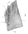
- Figure 1 is a schematic and partial perspective view of an embodiment of the camouflage cover according to the present invention, said embodiment being seen from above and from the outside.
- Figure 2 is a schematic cross section of the camouflage cover of Figure 1 along the line II-II thereof.
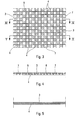
- FIG. 3 is a diagrammatic plan view of an embodiment of the camouflage net and the electrically conductive grid carried by the outer face of the cover according to the invention and shown in FIGS. 1 and 2.
- Figures 4 and 5 are schematic sections, respectively along the lines IV-IV and VV of Figure 3.
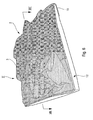
- Figure 6 is a schematic and partial perspective view of an alternative embodiment of the camouflage cover according to the present invention, seen from above and from the outside.
- Fig. 7 is a schematic cross-section of the cover of Fig. 6 along line VII-VII thereof.
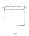
- FIG. 8 is a schematic plan view, on the inside, of the embodiment of FIGS. 6 and 7.
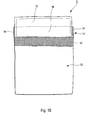
- FIGs 9 and 10 schematically illustrate the interchangeability of the cover of the cover according to the present invention and shown in Figures 6 to 8.
- the camouflage cover I comprises a sheet 1 made of a flexible material, for example a polymer such as a polyvinyl chloride, and having a thickness at most equal to at 0.5 mm, preferably of the order of 0.3 mm.
- the sheet 1 On its outer face 1 E, the sheet 1 carries a random set of gathers 2, constituted by a camouflage net 3, associated with a flexible dielectric grid 4, for example based on fibers or carbon particles.
- the gathers 2 result for example because the camouflage net 3 and the grid 4 are sewn to the sheet 1 by forming random projecting folds, leaving air pockets with said outer face 1 E.
- the grid 4 is on the inner side of the net 3, while the outer face of the latter carries camouflage patterns (see Figure 1), as is usual.
- the sheet 1 On its outer face 1E, the sheet 1 may carry a layer of paint or the like in color harmony with said camouflage patterns.
- FIGS. 3 to 5 there is shown a thread 3 provided with openings or meshes 6 formed in a support 7.
- the conductive grid 4 may be secured to the inner face of the net 3 by any known means.
- the cover I can be secured to an equipment 8 (shown schematically by dashed lines in FIG. inner face 1I of the sheet 1, so that the face 1E thereof and the ruffles 2 are directed outwardly of said equipment.
- the inner face 1I of the flexible sheet 1 carries a metallization film 9, in contact with the equipment 8.
- the conductivity of the flexible grid 4 of the cover I can be adjusted according to the desired applications and the possible presence of the metallization film 9.
- This conductivity referred to a homogeneous layer, can vary from 1 ⁇ -1 m -1 to 100 ⁇ -1 m -1 , and even beyond 100 ⁇ -1 cm -1 .
- the flexible sheet 1 is extended, on one side of the ruffles 2, by a wide flap 10 and, on the other side, by another flap 11, said flaps being intended to be applied against the equipment 8.
- the flexible sheet 1 also forms a flat cover 12, able to be closed by the cooperation of the flaps 10 and 11.
- fast fastening strips 13 and 14, for example of the type with loops and flexible hooks and respectively secured the flaps 10 and 11, cooperate with each other to fix said flaps together.
- a radar frequency absorbing plate 15 hermetically sealed in a flexible envelope 16, for example made of a polyethylene film.
- the plate 15 may be of the type known under the trade name AN74 available from EMERSON AND CUMING MICROWAVE PRODUCTS, Nijverheidsstraat 7A, 2260 WESTERLO - BELGIUM.
- the inner face 15I of the plate 15 is metallized.
- the flexible grid 4 of the gathers 2 has a very low complex permittivity less than 100 and preferably less than 10.
- the cover 12 can be opened by detaching the quick-release strips 13 and 14 and straightening the flap 11 (FIG. 9), after which the entire plate 15 and its envelope 16 can be removed from said cover ( Figure 10).
- the camouflage nets 3 carry different camouflage patterns, suitable for different environments.
Landscapes
- Engineering & Computer Science (AREA)
- General Engineering & Computer Science (AREA)
- Aiming, Guidance, Guns With A Light Source, Armor, Camouflage, And Targets (AREA)
- Shielding Devices Or Components To Electric Or Magnetic Fields (AREA)
- Laminated Bodies (AREA)
- Materials For Medical Uses (AREA)
- Casings For Electric Apparatus (AREA)
- Paints Or Removers (AREA)
Abstract
Description
- La présente invention concerne une couverture pour le camouflage contre les radiations électromagnétiques d'un équipement vis-à-vis d'un dispositif d'observation. Une telle couverture est particulièrement appropriée à protéger un équipement militaire, par exemple des- véhicules à l'arrêt ou en mouvement, contre la détection par des forces hostiles. A cet effet, ladite couverture est appliquée contre l'équipement à protéger.
- De telles couvertures de camouflage sont par exemple décrites dans les documents
US-4 479 994 ,US-4 659 602 ,WO 2004/020931 etWO 1988/01363 - Ces couvertures de camouflage connues sont généralement efficaces contre la détection par radar, mais en revanche elles n'assurent qu'une faible protection contre la détection par un dispositif d'observation fonctionnant dans les bandes I, II et III du rayonnement infrarouge.
- Pour remédier à cet inconvénient, on pourrait envisager de prévoir, dans lesdites couvertures de camouflage connues, une couche traitée pour la discrétion infrarouge, disposée du côté destiné à être dirigé vers l'extérieur de l'équipement à protéger. Cependant, l'efficacité d'une telle couche traitée pour la discrétion infrarouge est très limitée, le jour lorsqu'il y a du soleil, pour les bandes 1 et II de l'infrarouge. En effet, même si l'émissivité de ladite couche est faible, les couches positionnées derrière finissent par rayonner en emmagasinant progressivement de la chaleur.
- De plus, dans le cas où (comme dans le document
US-4 479 994 ) une telle couverture de camouflage comporte une pluralité de couches superposées, dont au moins l'une est constituée par une plaque souple d'un absorbant radar apte à absorber au moins en partie les hyperfréquences radar, l'expérience a montré qu'une telle couche traitée pour la discrétion infrarouge dégradait les performances de l'absorbant radar positionné derrière. Ce phénomène provient vraisemblablement du fait que le traitement infrarouge nécessite l'utilisation de pigments à faible émissivité, qui sont au moins partiellement électriquement conducteurs. Cette couche protectrice doit provoquer localement une variation brutale d'impédance qui est préjudiciable au fonctionnement de l'absorbant radar. Ce problème est d'autant plus marqué que l'on désire obtenir un complexe à plus faible émissivité. - La présente invention a pour objet de remédier à ces inconvénients et elle concerne une couverture de camouflage multispectral apte à absorber les hyperfréquences radar, à limiter la charge thermique pour éviter le rayonnement infrarouge dans les bandes I, II et III, tout en assurant le camouflage dans le domaine visible.
- A cette fin, selon l'invention, la couverture de camouflage contre les radiations électromagnétiques, comportant une feuille souple dont la face interne est destinée à être dirigée du côté d'un équipement à camoufler et dont la face externe est destinée à être dirigée vers l'extérieur dudit équipement, est remarquable en ce que ladite face externe de ladite feuille souple comporte un ensemble aléatoire de fronces, qui sont constituées par un filet de camouflage associé à une grille souple diélectrique et qui ménagent des poches d'air entre, d'une part, ledit filet de camouflage et ladite grille souple et, d'autre part, ladite face externe.
- Dans la couverture de camouflage conforme à la présente invention, ledit filet de camouflage, non seulement assure une protection dans le domaine visible par les dessins de camouflage qu'il porte extérieurement, mais encore présente des propriétés d'aération entre lesdites fronces et ladite face externe. Une telle aération permet à la couverture de rester à température ambiante pour limiter l'échauffement thermique et donc le rayonnement infrarouge.
- La couverture conforme à la présente invention ne nécessite donc pas la présence d'une couche traitée pour la discrétion infrarouge et élimine donc les inconvénients rappelés ci-dessus d'une telle couche.
- De préférence, ladite grille souple est solidaire dudit filet de camouflage, du côté interne de celui-ci. Elle peut être réalisée à base de tout matériau conducteur électrique, et plus particulièrement à base de carbone.
- Ladite feuille souple peut être réalisée en un polymère, tel qu'un chlorure de polyvinyle ou analogue, et son épaisseur est avantageusement au plus égale à 0,5 mm, de préférence au moins approximativement égale à 0,3 mm.
- La conductivité de ladite grille souple, rapportée à une couche homogène, peut être supérieure et même très supérieure à 100 Ω-1m-1, presque jusqu'à présenter une valeur proche d'un métal. Dans ce cas, les hyperfréquences ne sont pas absorbées par lesdites fronces, mais sont réfléchies dans toutes les directions. L'énergie renvoyée dans la direction d'un radar de détection est alors fortement réduite par diffraction et/ou diffusion dans les autres directions de l'espace.
- Toutefois, la conductivité de ladite grille souple, rapportée à une couche homogène, peut être comprise entre 1 et 100 Ω-1m-1. Dans ce cas, les interactions de l'onde électromagnétique sont complexes, car il s'agit d'une gamme de conductivité "intermédiaire". La structure à trois dimensions de ladite grille engendre de la diffraction et, probablement, de la diffusion vers les plus hautes fréquences et une certaine absorption par réflexions successives vers les plus basses fréquences. Selon la géométrie des équipements à camoufler, il peut être avantageux que ladite face interne de la feuille souple soit métallisée.
- Dans un mode de réalisation préféré de ladite couverture de camouflage, celle-ci comporte, du côté de ladite face interne de la feuille souple, une plaque d'absorbant radar à large bande et ladite grille souple diélectrique présente une permittivité complexe inférieure à 100 et, de préférence, inférieure à 10.
- On obtient alors une couverture de camouflage multispectral extrêmement performante non seulement dans les domaines visible et infrarouge, mais encore dans le domaine des hyperfréquences radar comprises entre 2 GHz et 100 GHz.
- Dans ce mode de réalisation préféré, on remarquera:
- que ladite feuille souple protège ladite plaque d'absorbant radar contre les intempéries ; et
- que tout risque de limitation des performances d'absorption de ladite plaque d'absorbant radar dans les bandes K et W (l'absorption des fréquences des bandes C, X et K restant efficace), du fait de la présence de ladite feuille souple, est compensé, de la façon décrite ci-dessus, par la structure à trois dimensions constituée par les fronces en relief formées par ladite grille souple.
- Par ailleurs, pour éviter tout risque de transmission des ondes électromagnétiques, ladite plaque d'absorbant radar peut porter un film métallisé sur sa face opposée à ladite feuille souple.
- Avantageusement, dans ce mode de réalisation préféré de la présente invention, ladite feuille souple forme une housse plate dans laquelle ladite plaque d'absorbant radar est logée de façon amovible. Bien entendu, une telle housse participe à la protection de ladite plaque d'absorbant radar.
- A des fins de protection supplémentaires, ladite plaque d'absorbant radar est de préférence enfermée de façon étanche dans une enveloppe, par exemple réalisée en un polymère, tel qu'un film de polyéthylène ou analogue.
- Du fait que ladite feuille souple forme une housse dans laquelle ladite plaque d'absorbant radar est logée de façon amovible, on peut associer à ladite plaque une pluralité de housses différentes, dont les filets portent des dessins de camouflage différents, respectivement appropriés à des environnements différents. Ainsi, ladite plaque d'absorbant radar -qui est l'élément le plus coûteux de la couverture de camouflage de la présente invention- peut être utilisée avec différentes houses, respectivement adaptées à un environnement particulier.
- Chaque housse peut être pourvue de moyens de fermeture, par exemple du type à boucles et crochets souples coopérants.
- Pour réaliser le camouflage complet d'un équipement de grande surface, il est possible de juxtaposer une pluralité de couvertures conformes à la présente invention.
- Les figures du dessin annexé feront bien comprendre comment l'invention peut être réalisée. Sur ces figures, des références identiques désignent des éléments semblables.
- La figure 1 est une vue en perspective schématique et partielle d'un mode de réalisation de la couverture de camouflage conforme à la présente invention, ledit mode de réalisation étant vu de haut et du côté extérieur.
- La figure 2 est une coupe transversale schématique de la couverture de camouflage de la figure 1, selon la ligne II-II de celle-ci.
- La figure 3 est une vue schématique en plan d'un mode de réalisation du filet de camouflage et de la grille électriquement conductrice portés par la face extérieure de la couverture conforme à l'invention et montrée par les figures 1 et 2.
- Les figures 4 et 5 sont des coupes schématiques, respectivement selon les lignes IV-IV et V-V de la figure 3.
- La figure 6 est une vue en perspective schématique et partielle d'une variante de réalisation de la couverture de camouflage conforme à la présente invention, vue du haut et du côté extérieur.
- La figure 7 est une coupe transversale schématique de la couverture de la figure 6, selon la ligne VII-VII de celle-ci.
- La figure 8 est une vue en plan schématique, du côté intérieur, du mode de réalisation des figures 6 et 7.
- Les figures 9 et 10 illustrent de façon schématique l'interchangeabilité de la housse de la couverture conforme à la présente invention et montrée par les figures 6 à 8.
- La couverture de camouflage I, conforme à la présente invention et montrée par les figures 1 et 2, comporte une feuille 1 réalisée en une matière souple, par exemple en un polymère tel qu'un chlorure de polyvinyle, et présentant une épaisseur au plus égale à 0,5 mm, de préférence de l'ordre de 0,3 mm.
- Sur sa face externe 1 E, la feuille 1 porte un ensemble aléatoire de fronces 2, constituées par un filet de camouflage 3, associé à une grille souple 4 diélectrique, par exemple à base de fibres ou de particules de carbone. Les fronces 2 résultent par exemple du fait que le filet de camouflage 3 et la grille 4 sont cousus à la feuille 1 en formant des plis saillants aléatoires, ménageant des poches d'air avec ladite face externe 1 E.
- De préférence, la grille 4 se trouve du côté intérieur du filet 3, alors que la face externe de ce dernier porte des dessins de camouflage (voir la figure 1), comme cela est usuel.
- Sur sa face externe 1 E, la feuille 1 peut porter une couche de peinture ou analogue 5 en harmonie de couleurs avec lesdits dessins de camouflage.
- Dans le mode de réalisation illustré par les figures 3 à 5, on a représenté un filet 3 pourvu d'ouvertures ou mailles 6 formées dans un support souple 7. La grille conductrice 4 peut être solidaire de la face interne du filet 3 par tout moyen connu.
- Par l'intermédiaire de tous moyens connus et non représentés (sangles, boutons-pression, crochets, etc ...), la couverture I peut être solidarisée d'un équipement 8 (schématisé par des tirets mixtes sur la figure 2) par la face interne 1I de la feuille 1, de façon que la face 1 E de celle-ci et les fronces 2 soient dirigées vers l'extérieur dudit équipement.
- Eventuellement, la face interne 1I de la feuille souple 1 porte un film de métallisation 9, au contact de l'équipement 8.
- Comme indiqué ci-dessus, la conductivité de la grille souple 4 de la couverture I peut être ajustée en fonction des applications désirées et de l'éventuelle présence du film de métallisation 9. Cette conductivité, rapportée à une couche homogène, peut varier de 1 Ω-1m-1 à 100 Ω-1m-1, et même au-delà de 100 Ω-1 cm-1.
- Dans le mode de réalisation II de la couverture de camouflage selon l'invention, montré par les figures 6 à 10, on retrouve les éléments 1 à 8 décrits ci-dessus. Dans cette variante, la feuille souple 1 est prolongée, d'un côté des fronces 2, par un large rabat 10 et, de l'autre côté, par un autre rabat 11, lesdits rabats étant destinés à s'appliquer contre l'équipement 8. La feuille souple 1 forme aussi une housse plate 12, apte à être obturée par la coopération des rabats 10 et 11. A cet effet, des bandes d'attache rapide 13 et 14, par exemple du type à boucles et à crochets souples, et respectivement solidarisées des rabats 10 et 11, coopèrent l'une avec l'autre pour fixer lesdits rabats entre eux.
- A l'intérieur de la housse 12, peut être disposée une plaque d'absorbant des fréquences radar 15, hermétiquement scellée dans une enveloppe souple 16, par exemple réalisée en un film de polyéthylène. La plaque 15 peut être du type connu sous le nom commercial AN74 disponible auprès de la société EMERSON AND CUMING MICROWAVE PRODUCTS, Nijverheidsstraat 7A, 2260 WESTERLO - BELGIQUE. La face interne 15I de la plaque 15 est métallisée.
- Dans la couverture de camouflage II, la grille souple 4 des fronces 2 présente une très faible permittivité complexe inférieure à 100 et, de préférence, inférieure à 10.
- Comme l'illustrent les figures 8 à 10, la housse 12 peut être ouverte par désolidarisation des bandes d'attache rapide 13 et 14 et redressement du rabat 11 (figure 9), après quoi l'ensemble de la plaque 15 et de son enveloppe étanche 16 peut être sorti de ladite housse (figure 10).
- Grâce à cette amovibilité de l'ensemble plaque 15 - enveloppe 16, celui-ci peut coopérer avec plusieurs housses 12 différentes, dont les filets de camouflage 3 portent des dessins de camouflage différents, adaptés à des environnements différents.
Claims (20)
- Couverture de camouflage (I, II) contre les radiations électromagnétiques, comportant une feuille souple (1) dont la face interne (1I) est destinée à être dirigée du côté d'un équipement (8) à camoufler et dont la face externe (1E) est destinée à être dirigée vers l'extérieur dudit équipement (8),
caractérisée en ce que ladite face externe (1 E) de ladite feuille souple (1) comporte un ensemble aléatoire de fronces (2), qui sont constituées par un filet de camouflage (3) associé à une grille souple diélectrique (4) et qui ménagent des poches d'air entre, d'une part, ledit filet de camouflage (3) et ladite grille souple (4) et, d'autre part, ladite face externe (1 E). - Couverture selon la revendication 1,
caractérisée en ce que ladite grille souple (4) est solidaire dudit filet de camouflage (3). - Couverture selon l'une des revendications 1 ou 2,
caractérisée en ce que ladite grille souple (4) se trouve du côté interne dudit filet de camouflage (3). - Couverture selon l'une des revendications 1 à 3,
caractérisée en ce que ladite grille souple (4) est à base de carbone. - Couverture selon l'une des revendications 1 à 4,
caractérisée en ce que ladite feuille souple (1) est réalisée en un polymère, tel qu'un chlorure de polyvinyle ou analogue. - Couverture selon la revendication 5,
caractérisée en ce que l'épaisseur de ladite feuille souple (1) est au plus égale à 0,5 mm. - Couverture selon la revendication 6,
caractérisée en ce que l'épaisseur de ladite feuille souple (1) est au moins approximativement égale à 0,3 mm. - Couverture selon l'une des revendications 1 à 7,
caractérisée en ce que la conductivité, rapportée à une couche homogène, de ladite grille souple (4) est supérieure à 100 Ω-1m-1. - Couverture selon l'une des revendications 1 à 7,
caractérisée en ce que la conductivité, rapportée à une couche homogène, de ladite grille souple (4) est comprise entre 1 Ω-1m-1 et 100 Ω-1m-1. - Couverture selon la revendication 9,
caractérisée en ce que ladite face interne de la feuille souple porte une couche de métallisation (9). - Couverture selon l'une des revendications 1 à 7,
caractérisée en ce que, du côté de ladite face interne (1 E) de la feuille souple (1), elle comporte une plaque d'absorbant radar à large bande (15). - Couverture selon la revendication 11,
caractérisée en ce que la permittivité complexe de ladite grille souple (4) est inférieure à 100. - Couverture selon la revendication 12,
caractérisée en ce que la permittivité complexe de ladite grille souple (4) est inférieure à 10. - Couverture selon l'une des revendications 11 à 13,
caractérisée en ce que la face (15I) de ladite plaque d'absorbant radar (15), opposée auxdites fronces (2), est métallisée. - Couverture selon l'une des revendications 11 à 14,
caractérisée en ce que ladite feuille souple (1) forme une housse plate (12) dans laquelle ladite plaque d'absorbant radar (15) est logée de façon amovible. - Couverture selon l'une des revendications 1 à 15,
caractérisée en ce que ladite plaque d'absorbant radar (15) est enfermée dans une enveloppe étanche (16). - Couverture selon la revendication 16,
caractérisée en ce que ladite enveloppe étanche (16) est réalisée en un polymère, tel qu'un film de polyéthylène ou analogue. - Couverture selon l'une des revendications 11 à 17,
caractérisé en ce que, à ladite plaque d'absorbant radar amovible (15), sont associées plusieurs housses plates (12) dont les filets (3) portent des dessins de camouflage différents, respectivement appropriés à des environnements différents. - Couverture selon l'une des revendications 15 à 18,
caractérisé en ce que ladite housse (12) est pourvue de moyens de fermeture rapide (13,14). - Camouflage pour un équipement (15),
caractérisé en ce qu'il comporte une pluralité de couvertures, telles que celles spécifiées sous l'une quelconque des revendications 1 à 19, juxtaposées sur ledit équipement (8).
Priority Applications (1)
| Application Number | Priority Date | Filing Date | Title |
|---|---|---|---|
| PL07291080T PL1901024T3 (pl) | 2006-09-14 | 2007-09-10 | Koc maskujący przed promieniowaniem elektromagnetycznym |
Applications Claiming Priority (1)
| Application Number | Priority Date | Filing Date | Title |
|---|---|---|---|
| FR0608040A FR2906021B1 (fr) | 2006-09-14 | 2006-09-14 | Couverture de camouflage multispectral. |
Publications (2)
| Publication Number | Publication Date |
|---|---|
| EP1901024A1 true EP1901024A1 (fr) | 2008-03-19 |
| EP1901024B1 EP1901024B1 (fr) | 2008-11-26 |
Family
ID=37944842
Family Applications (1)
| Application Number | Title | Priority Date | Filing Date |
|---|---|---|---|
| EP20070291080 Active EP1901024B1 (fr) | 2006-09-14 | 2007-09-10 | Couverture de camouflage contre les radiations éléctromagnétiques |
Country Status (11)
| Country | Link |
|---|---|
| US (1) | US8030228B2 (fr) |
| EP (1) | EP1901024B1 (fr) |
| AT (1) | ATE415608T1 (fr) |
| AU (1) | AU2007296087B2 (fr) |
| CA (1) | CA2659755C (fr) |
| DE (1) | DE602007000295D1 (fr) |
| ES (1) | ES2317633T3 (fr) |
| FR (1) | FR2906021B1 (fr) |
| IL (1) | IL196752A (fr) |
| PL (1) | PL1901024T3 (fr) |
| WO (1) | WO2008031934A1 (fr) |
Families Citing this family (10)
| Publication number | Priority date | Publication date | Assignee | Title |
|---|---|---|---|---|
| US8646373B1 (en) * | 2009-05-04 | 2014-02-11 | Nova Research, Inc. | Blast wave effects reduction system |
| US8410461B2 (en) * | 2010-04-22 | 2013-04-02 | Michael D. Slinkard | Methods and apparel for attenuating electromagnetic fields emanating from a person in a human adversarial situation |
| US20130081193A1 (en) * | 2011-09-29 | 2013-04-04 | Leonard Angelo Wallace, SR. | Leisure Arctic Wear / Lethal Attack Wear L.A.W. 2000 |
| WO2014210506A2 (fr) * | 2013-06-28 | 2014-12-31 | Associated Universities, Inc. | Réflecteur à surface aléatoire |
| US10156427B2 (en) | 2014-12-11 | 2018-12-18 | Stanislaw Litwin | Multi-spectral camouflage device and method |
| US20200240752A1 (en) * | 2017-08-14 | 2020-07-30 | Kumutha N | Invisibility cloaking device |
| USD977787S1 (en) * | 2021-03-16 | 2023-02-14 | Nfm As | Ghillie for helmets camouflage |
| CN113172952B (zh) * | 2021-04-12 | 2023-02-21 | 上海戎科特种装备有限公司 | 一种p波段雷达衰减轻质结构及其制备方法 |
| SE547644C2 (en) * | 2021-10-18 | 2025-11-04 | Saab Ab | A product and method for frequency selective camouflage material |
| US12540797B2 (en) * | 2023-07-26 | 2026-02-03 | Sean Hokenstrom | Covering device providing visual and thermal masking characteristics |
Citations (5)
| Publication number | Priority date | Publication date | Assignee | Title |
|---|---|---|---|---|
| DE1094163B (de) * | 1952-11-13 | 1960-12-01 | Oberndorfer Gardinen Und Spitz | Tarnnetz |
| US4479994A (en) | 1983-05-18 | 1984-10-30 | The United States Of America As Represented By The Secretary Of The Army | Wide band energy absorbing camouflage blanket |
| US4659602A (en) | 1985-11-12 | 1987-04-21 | Jorgen Birch | Broad spectrum camouflage mat |
| WO1988001363A1 (fr) | 1986-08-21 | 1988-02-25 | Hb Radicool Research & Development | Materiau en bande pour le camouflage d'objets pouvant etre detectes par un rayonnement electromagnetique |
| WO2004020931A1 (fr) | 2002-08-30 | 2004-03-11 | W.L. Gore & Associates Gmbh | Materiau de couverture reflechissant les infrarouges |
Family Cites Families (5)
| Publication number | Priority date | Publication date | Assignee | Title |
|---|---|---|---|---|
| DE1916326A1 (de) * | 1968-04-01 | 1969-10-30 | Barracudaverken Ab | Tarnungsmittel zum Verhindern oder Hemmen der Entdeckung durch Radarerkundung |
| US5881409A (en) * | 1993-06-22 | 1999-03-16 | Teksource, Ll | Puff-quilted bladders for containing flowable cushioning medium |
| ATE200570T1 (de) * | 1997-02-12 | 2001-04-15 | Schweizerische Eidgenossenschaft Eidgenoessisches Militaer Departement Gruppe Ruestung | Tarnstruktur |
| GB0317363D0 (en) * | 2003-07-24 | 2003-08-27 | Omnova Wallcovering Uk Ltd | Camouflage covering |
| US20070281562A1 (en) * | 2006-06-02 | 2007-12-06 | Kohlman Randolph S | Building construction composite having one or more reinforcing scrim layers |
-
2006
- 2006-09-14 FR FR0608040A patent/FR2906021B1/fr not_active Expired - Fee Related
-
2007
- 2007-09-10 EP EP20070291080 patent/EP1901024B1/fr active Active
- 2007-09-10 AT AT07291080T patent/ATE415608T1/de active
- 2007-09-10 US US12/441,338 patent/US8030228B2/en active Active
- 2007-09-10 PL PL07291080T patent/PL1901024T3/pl unknown
- 2007-09-10 AU AU2007296087A patent/AU2007296087B2/en active Active
- 2007-09-10 DE DE200760000295 patent/DE602007000295D1/de active Active
- 2007-09-10 ES ES07291080T patent/ES2317633T3/es active Active
- 2007-09-10 CA CA 2659755 patent/CA2659755C/fr active Active
- 2007-09-10 WO PCT/FR2007/001455 patent/WO2008031934A1/fr not_active Ceased
-
2009
- 2009-01-27 IL IL196752A patent/IL196752A/en active IP Right Grant
Patent Citations (5)
| Publication number | Priority date | Publication date | Assignee | Title |
|---|---|---|---|---|
| DE1094163B (de) * | 1952-11-13 | 1960-12-01 | Oberndorfer Gardinen Und Spitz | Tarnnetz |
| US4479994A (en) | 1983-05-18 | 1984-10-30 | The United States Of America As Represented By The Secretary Of The Army | Wide band energy absorbing camouflage blanket |
| US4659602A (en) | 1985-11-12 | 1987-04-21 | Jorgen Birch | Broad spectrum camouflage mat |
| WO1988001363A1 (fr) | 1986-08-21 | 1988-02-25 | Hb Radicool Research & Development | Materiau en bande pour le camouflage d'objets pouvant etre detectes par un rayonnement electromagnetique |
| WO2004020931A1 (fr) | 2002-08-30 | 2004-03-11 | W.L. Gore & Associates Gmbh | Materiau de couverture reflechissant les infrarouges |
Also Published As
| Publication number | Publication date |
|---|---|
| AU2007296087B2 (en) | 2012-06-07 |
| FR2906021A1 (fr) | 2008-03-21 |
| EP1901024B1 (fr) | 2008-11-26 |
| US8030228B2 (en) | 2011-10-04 |
| PL1901024T3 (pl) | 2009-05-29 |
| IL196752A0 (en) | 2009-11-18 |
| CA2659755C (fr) | 2014-02-25 |
| FR2906021B1 (fr) | 2008-11-21 |
| DE602007000295D1 (de) | 2009-01-08 |
| CA2659755A1 (fr) | 2008-03-20 |
| ATE415608T1 (de) | 2008-12-15 |
| US20090317596A1 (en) | 2009-12-24 |
| AU2007296087A1 (en) | 2008-03-20 |
| IL196752A (en) | 2013-01-31 |
| ES2317633T3 (es) | 2009-04-16 |
| WO2008031934A1 (fr) | 2008-03-20 |
Similar Documents
| Publication | Publication Date | Title |
|---|---|---|
| EP1901024B1 (fr) | Couverture de camouflage contre les radiations éléctromagnétiques | |
| FR2516645A1 (fr) | Dispositif de camouflage | |
| CA1260610A (fr) | Antenne reseau sur circuit imprime | |
| FR2790731A1 (fr) | Procede de simulation des flux thermiques externes absorbes en vol par les elements radiatifs exterieurs d'un engin spatial et engin spatial pour la mise en oeuvre de ce procede | |
| EP0816793A1 (fr) | Revêtement pour la protection personnelle d'un fantassin | |
| EP1436197B1 (fr) | Reflecteur optique de surface, pour un engin spatial tel qu'un satellite geostationnaire | |
| EP1626133A1 (fr) | Isolation multicouche | |
| Zheng et al. | Wideband radar absorbing material combining high-impedance transmission line and circuit analogue screen | |
| CN117559147A (zh) | 一种宽带和双频段可调谐的太赫兹吸波器 | |
| FR2958449A1 (fr) | Dispositif de controle thermique d'un tube a collecteur rayonnant | |
| EP0887260B1 (fr) | Satellite à rejet thermique amélioré | |
| EP4057789A1 (fr) | Dispositif et procédé pour neutraliser la transmission d'ondes électromagnétiques par écrantage au moyen d'un contenant porteur de dispositifs électriques ou électroniques qui les protège électromagnétiquement et les rend indétectables électromagnétiquement | |
| FR2941989A1 (fr) | Lame bi-compsant pour volet roulant | |
| FR2736160A1 (fr) | Dispositif anti-detection pour antenne radar | |
| JPH01254003A (ja) | レフレクタアンテナ | |
| FR3109027A1 (fr) | Absorbant radar large bande ajustable | |
| EP2772985A1 (fr) | Système de fixation d'un radôme plan sur le réflecteur concave d'une antenne | |
| EP2331429B1 (fr) | Element protecteur pour organe a proteger notamment un flexible d'echappement | |
| FR2469806A1 (fr) | Agencement de dispositifs photovoltaiques | |
| FR3009444A1 (fr) | Bache de protection | |
| FR2505540A1 (fr) | Structure anti-diffusion des rayonnements | |
| FR3019884A1 (fr) | Surface thermoelectrique semi-transparente comprenant un radiateur polarisant sur chaque face | |
| FR2469671A2 (fr) | Element absorbant l'energie solaire, capteur solaire equipe d'un tel element, et panneau solaire comportant de tels capteurs | |
| BE623959A (fr) | ||
| FR2960246A1 (fr) | Lanterneau d'eclairage zenithal avec protection solaire |
Legal Events
| Date | Code | Title | Description |
|---|---|---|---|
| PUAI | Public reference made under article 153(3) epc to a published international application that has entered the european phase |
Free format text: ORIGINAL CODE: 0009012 |
|
| AK | Designated contracting states |
Kind code of ref document: A1 Designated state(s): AT BE BG CH CY CZ DE DK EE ES FI FR GB GR HU IE IS IT LI LT LU LV MC MT NL PL PT RO SE SI SK TR |
|
| AX | Request for extension of the european patent |
Extension state: AL BA HR MK YU |
|
| 17P | Request for examination filed |
Effective date: 20080327 |
|
| GRAP | Despatch of communication of intention to grant a patent |
Free format text: ORIGINAL CODE: EPIDOSNIGR1 |
|
| GRAS | Grant fee paid |
Free format text: ORIGINAL CODE: EPIDOSNIGR3 |
|
| GRAA | (expected) grant |
Free format text: ORIGINAL CODE: 0009210 |
|
| AK | Designated contracting states |
Kind code of ref document: B1 Designated state(s): AT BE BG CH CY CZ DE DK EE ES FI FR GB GR HU IE IS IT LI LT LU LV MC MT NL PL PT RO SE SI SK TR |
|
| REG | Reference to a national code |
Ref country code: GB Ref legal event code: FG4D Free format text: NOT ENGLISH |
|
| REG | Reference to a national code |
Ref country code: CH Ref legal event code: EP |
|
| REG | Reference to a national code |
Ref country code: IE Ref legal event code: FG4D Free format text: LANGUAGE OF EP DOCUMENT: FRENCH |
|
| REF | Corresponds to: |
Ref document number: 602007000295 Country of ref document: DE Date of ref document: 20090108 Kind code of ref document: P |
|
| REG | Reference to a national code |
Ref country code: CH Ref legal event code: NV Representative=s name: CRONIN INTELLECTUAL PROPERTY |
|
| REG | Reference to a national code |
Ref country code: SE Ref legal event code: TRGR |
|
| REG | Reference to a national code |
Ref country code: GR Ref legal event code: EP Ref document number: 20090400389 Country of ref document: GR |
|
| REG | Reference to a national code |
Ref country code: ES Ref legal event code: FG2A Ref document number: 2317633 Country of ref document: ES Kind code of ref document: T3 |
|
| PG25 | Lapsed in a contracting state [announced via postgrant information from national office to epo] |
Ref country code: LT Free format text: LAPSE BECAUSE OF FAILURE TO SUBMIT A TRANSLATION OF THE DESCRIPTION OR TO PAY THE FEE WITHIN THE PRESCRIBED TIME-LIMIT Effective date: 20081126 |
|
| PG25 | Lapsed in a contracting state [announced via postgrant information from national office to epo] |
Ref country code: SI Free format text: LAPSE BECAUSE OF FAILURE TO SUBMIT A TRANSLATION OF THE DESCRIPTION OR TO PAY THE FEE WITHIN THE PRESCRIBED TIME-LIMIT Effective date: 20081126 Ref country code: LV Free format text: LAPSE BECAUSE OF FAILURE TO SUBMIT A TRANSLATION OF THE DESCRIPTION OR TO PAY THE FEE WITHIN THE PRESCRIBED TIME-LIMIT Effective date: 20081126 Ref country code: IS Free format text: LAPSE BECAUSE OF FAILURE TO SUBMIT A TRANSLATION OF THE DESCRIPTION OR TO PAY THE FEE WITHIN THE PRESCRIBED TIME-LIMIT Effective date: 20090326 Ref country code: FI Free format text: LAPSE BECAUSE OF FAILURE TO SUBMIT A TRANSLATION OF THE DESCRIPTION OR TO PAY THE FEE WITHIN THE PRESCRIBED TIME-LIMIT Effective date: 20081126 |
|
| REG | Reference to a national code |
Ref country code: PL Ref legal event code: T3 |
|
| REG | Reference to a national code |
Ref country code: IE Ref legal event code: FD4D |
|
| PG25 | Lapsed in a contracting state [announced via postgrant information from national office to epo] |
Ref country code: RO Free format text: LAPSE BECAUSE OF FAILURE TO SUBMIT A TRANSLATION OF THE DESCRIPTION OR TO PAY THE FEE WITHIN THE PRESCRIBED TIME-LIMIT Effective date: 20081126 Ref country code: IE Free format text: LAPSE BECAUSE OF FAILURE TO SUBMIT A TRANSLATION OF THE DESCRIPTION OR TO PAY THE FEE WITHIN THE PRESCRIBED TIME-LIMIT Effective date: 20081126 Ref country code: EE Free format text: LAPSE BECAUSE OF FAILURE TO SUBMIT A TRANSLATION OF THE DESCRIPTION OR TO PAY THE FEE WITHIN THE PRESCRIBED TIME-LIMIT Effective date: 20081126 Ref country code: DK Free format text: LAPSE BECAUSE OF FAILURE TO SUBMIT A TRANSLATION OF THE DESCRIPTION OR TO PAY THE FEE WITHIN THE PRESCRIBED TIME-LIMIT Effective date: 20081126 Ref country code: BG Free format text: LAPSE BECAUSE OF FAILURE TO SUBMIT A TRANSLATION OF THE DESCRIPTION OR TO PAY THE FEE WITHIN THE PRESCRIBED TIME-LIMIT Effective date: 20090226 |
|
| PG25 | Lapsed in a contracting state [announced via postgrant information from national office to epo] |
Ref country code: PT Free format text: LAPSE BECAUSE OF FAILURE TO SUBMIT A TRANSLATION OF THE DESCRIPTION OR TO PAY THE FEE WITHIN THE PRESCRIBED TIME-LIMIT Effective date: 20090427 |
|
| PG25 | Lapsed in a contracting state [announced via postgrant information from national office to epo] |
Ref country code: SK Free format text: LAPSE BECAUSE OF FAILURE TO SUBMIT A TRANSLATION OF THE DESCRIPTION OR TO PAY THE FEE WITHIN THE PRESCRIBED TIME-LIMIT Effective date: 20081126 |
|
| PLBE | No opposition filed within time limit |
Free format text: ORIGINAL CODE: 0009261 |
|
| STAA | Information on the status of an ep patent application or granted ep patent |
Free format text: STATUS: NO OPPOSITION FILED WITHIN TIME LIMIT |
|
| 26N | No opposition filed |
Effective date: 20090827 |
|
| PG25 | Lapsed in a contracting state [announced via postgrant information from national office to epo] |
Ref country code: MC Free format text: LAPSE BECAUSE OF NON-PAYMENT OF DUE FEES Effective date: 20090930 |
|
| PG25 | Lapsed in a contracting state [announced via postgrant information from national office to epo] |
Ref country code: DE Free format text: LAPSE BECAUSE OF NON-PAYMENT OF DUE FEES Effective date: 20100401 |
|
| PG25 | Lapsed in a contracting state [announced via postgrant information from national office to epo] |
Ref country code: LU Free format text: LAPSE BECAUSE OF NON-PAYMENT OF DUE FEES Effective date: 20090910 |
|
| PG25 | Lapsed in a contracting state [announced via postgrant information from national office to epo] |
Ref country code: HU Free format text: LAPSE BECAUSE OF FAILURE TO SUBMIT A TRANSLATION OF THE DESCRIPTION OR TO PAY THE FEE WITHIN THE PRESCRIBED TIME-LIMIT Effective date: 20090527 |
|
| PG25 | Lapsed in a contracting state [announced via postgrant information from national office to epo] |
Ref country code: TR Free format text: LAPSE BECAUSE OF FAILURE TO SUBMIT A TRANSLATION OF THE DESCRIPTION OR TO PAY THE FEE WITHIN THE PRESCRIBED TIME-LIMIT Effective date: 20081126 |
|
| PG25 | Lapsed in a contracting state [announced via postgrant information from national office to epo] |
Ref country code: CY Free format text: LAPSE BECAUSE OF FAILURE TO SUBMIT A TRANSLATION OF THE DESCRIPTION OR TO PAY THE FEE WITHIN THE PRESCRIBED TIME-LIMIT Effective date: 20081126 |
|
| REG | Reference to a national code |
Ref country code: DE Ref legal event code: R073 Ref document number: 602007000295 Country of ref document: DE |
|
| REG | Reference to a national code |
Ref country code: DE Ref legal event code: R074 Ref document number: 602007000295 Country of ref document: DE Ref country code: DE Ref legal event code: R073 Ref document number: 602007000295 Country of ref document: DE |
|
| REG | Reference to a national code |
Ref country code: DE Ref legal event code: R074 Ref document number: 602007000295 Country of ref document: DE Effective date: 20111222 |
|
| PGRI | Patent reinstated in contracting state [announced from national office to epo] |
Ref country code: DE Effective date: 20111219 |
|
| REG | Reference to a national code |
Ref country code: FR Ref legal event code: PLFP Year of fee payment: 9 |
|
| REG | Reference to a national code |
Ref country code: FR Ref legal event code: PLFP Year of fee payment: 10 |
|
| REG | Reference to a national code |
Ref country code: FR Ref legal event code: PLFP Year of fee payment: 11 |
|
| REG | Reference to a national code |
Ref country code: CH Ref legal event code: PCAR Free format text: NEW ADDRESS: CHEMIN DE LA VUARPILLIERE 29, 1260 NYON (CH) |
|
| REG | Reference to a national code |
Ref country code: FR Ref legal event code: PLFP Year of fee payment: 12 |
|
| P01 | Opt-out of the competence of the unified patent court (upc) registered |
Effective date: 20230630 |
|
| REG | Reference to a national code |
Ref country code: CH Ref legal event code: U11 Free format text: ST27 STATUS EVENT CODE: U-0-0-U10-U11 (AS PROVIDED BY THE NATIONAL OFFICE) Effective date: 20251001 |
|
| PGFP | Annual fee paid to national office [announced via postgrant information from national office to epo] |
Ref country code: DE Payment date: 20250916 Year of fee payment: 19 |
|
| PGFP | Annual fee paid to national office [announced via postgrant information from national office to epo] |
Ref country code: GR Payment date: 20250820 Year of fee payment: 19 |
|
| PGFP | Annual fee paid to national office [announced via postgrant information from national office to epo] |
Ref country code: PL Payment date: 20250825 Year of fee payment: 19 Ref country code: NL Payment date: 20250909 Year of fee payment: 19 Ref country code: IT Payment date: 20250910 Year of fee payment: 19 |
|
| PGFP | Annual fee paid to national office [announced via postgrant information from national office to epo] |
Ref country code: BE Payment date: 20250919 Year of fee payment: 19 Ref country code: GB Payment date: 20250919 Year of fee payment: 19 |
|
| PGFP | Annual fee paid to national office [announced via postgrant information from national office to epo] |
Ref country code: AT Payment date: 20250822 Year of fee payment: 19 Ref country code: FR Payment date: 20250929 Year of fee payment: 19 |
|
| PGFP | Annual fee paid to national office [announced via postgrant information from national office to epo] |
Ref country code: SE Payment date: 20250925 Year of fee payment: 19 |
|
| PGFP | Annual fee paid to national office [announced via postgrant information from national office to epo] |
Ref country code: CZ Payment date: 20250910 Year of fee payment: 19 |
|
| PGFP | Annual fee paid to national office [announced via postgrant information from national office to epo] |
Ref country code: CH Payment date: 20251001 Year of fee payment: 19 |
|
| PGFP | Annual fee paid to national office [announced via postgrant information from national office to epo] |
Ref country code: ES Payment date: 20251015 Year of fee payment: 19 |