EP1900973A1 - Transmission system for pump drive - Google Patents
Transmission system for pump drive Download PDFInfo
- Publication number
- EP1900973A1 EP1900973A1 EP06291449A EP06291449A EP1900973A1 EP 1900973 A1 EP1900973 A1 EP 1900973A1 EP 06291449 A EP06291449 A EP 06291449A EP 06291449 A EP06291449 A EP 06291449A EP 1900973 A1 EP1900973 A1 EP 1900973A1
- Authority
- EP
- European Patent Office
- Prior art keywords
- pump
- drive
- gear
- prime mover
- transmission system
- Prior art date
- Legal status (The legal status is an assumption and is not a legal conclusion. Google has not performed a legal analysis and makes no representation as to the accuracy of the status listed.)
- Granted
Links
Images

Classifications
-
- F—MECHANICAL ENGINEERING; LIGHTING; HEATING; WEAPONS; BLASTING
- F04—POSITIVE - DISPLACEMENT MACHINES FOR LIQUIDS; PUMPS FOR LIQUIDS OR ELASTIC FLUIDS
- F04B—POSITIVE-DISPLACEMENT MACHINES FOR LIQUIDS; PUMPS
- F04B9/00—Piston machines or pumps characterised by the driving or driven means to or from their working members
- F04B9/02—Piston machines or pumps characterised by the driving or driven means to or from their working members the means being mechanical
-
- F—MECHANICAL ENGINEERING; LIGHTING; HEATING; WEAPONS; BLASTING
- F04—POSITIVE - DISPLACEMENT MACHINES FOR LIQUIDS; PUMPS FOR LIQUIDS OR ELASTIC FLUIDS
- F04B—POSITIVE-DISPLACEMENT MACHINES FOR LIQUIDS; PUMPS
- F04B17/00—Pumps characterised by combination with, or adaptation to, specific driving engines or motors
- F04B17/05—Pumps characterised by combination with, or adaptation to, specific driving engines or motors driven by internal-combustion engines
-
- F—MECHANICAL ENGINEERING; LIGHTING; HEATING; WEAPONS; BLASTING
- F16—ENGINEERING ELEMENTS AND UNITS; GENERAL MEASURES FOR PRODUCING AND MAINTAINING EFFECTIVE FUNCTIONING OF MACHINES OR INSTALLATIONS; THERMAL INSULATION IN GENERAL
- F16H—GEARING
- F16H47/00—Combinations of mechanical gearing with fluid clutches or fluid gearing
- F16H47/02—Combinations of mechanical gearing with fluid clutches or fluid gearing the fluid gearing being of the volumetric type
- F16H47/04—Combinations of mechanical gearing with fluid clutches or fluid gearing the fluid gearing being of the volumetric type the mechanical gearing being of the type with members having orbital motion
-
- F—MECHANICAL ENGINEERING; LIGHTING; HEATING; WEAPONS; BLASTING
- F16—ENGINEERING ELEMENTS AND UNITS; GENERAL MEASURES FOR PRODUCING AND MAINTAINING EFFECTIVE FUNCTIONING OF MACHINES OR INSTALLATIONS; THERMAL INSULATION IN GENERAL
- F16H—GEARING
- F16H37/00—Combinations of mechanical gearings, not provided for in groups F16H1/00 - F16H35/00
- F16H37/02—Combinations of mechanical gearings, not provided for in groups F16H1/00 - F16H35/00 comprising essentially only toothed or friction gearings
- F16H37/06—Combinations of mechanical gearings, not provided for in groups F16H1/00 - F16H35/00 comprising essentially only toothed or friction gearings with a plurality of driving or driven shafts; with arrangements for dividing torque between two or more intermediate shafts
- F16H37/08—Combinations of mechanical gearings, not provided for in groups F16H1/00 - F16H35/00 comprising essentially only toothed or friction gearings with a plurality of driving or driven shafts; with arrangements for dividing torque between two or more intermediate shafts with differential gearing
- F16H37/0833—Combinations of mechanical gearings, not provided for in groups F16H1/00 - F16H35/00 comprising essentially only toothed or friction gearings with a plurality of driving or driven shafts; with arrangements for dividing torque between two or more intermediate shafts with differential gearing with arrangements for dividing torque between two or more intermediate shafts, i.e. with two or more internal power paths
- F16H37/084—Combinations of mechanical gearings, not provided for in groups F16H1/00 - F16H35/00 comprising essentially only toothed or friction gearings with a plurality of driving or driven shafts; with arrangements for dividing torque between two or more intermediate shafts with differential gearing with arrangements for dividing torque between two or more intermediate shafts, i.e. with two or more internal power paths at least one power path being a continuously variable transmission, i.e. CVT
- F16H2037/088—Power-split transmissions with summing differentials, with the input of the CVT connected or connectable to the input shaft
Definitions
- the present invention relates to transmission systems for taking drive from a prime mover to an operating unit.
- the invention related to such a transmission for use in driving pump, especially pumps of the type used in the oil and gas exploration and production industries for fracturing and cementing operations.
- fracturing pump setup In a typical fracturing pump setup, several pumps are used, each typically being fitted with a diesel engine as primary driver for a high pressure triplex or quintuplex positive displacement pump, coupled through a five to seven speed transmission. Each pump typically delivers between 1500 to 2000 HP depending on the type and size of the engine fitted. Large fracturing operations can require more than 16 pumping units to be available at the well site to meet the pumping power requirements and provide backup in case of failure of individual units.
- a stand-by unit In the event that an active pump fails during the operation, a stand-by unit is required to take its place. In this case the stand-by pump will need to start against a high pressure from standstill. In order to do this, operators must put the engine at speed and engage the desired gear.
- the transmissions typically used are fitted with a torque converter that allows a limited amount of slip between engine speed and pump speed. However the unit will only tolerate running with such internal slippage for a very limited amount of time.
- HST hydrostatic transmission
- Such systems provide a gearless drive mechanism that translates engine power to hydraulic power continuously.
- Such systems are widely applied in construction machinery, because of their superior speed changeability.
- HST does have certain problems that make is unsuitable for pumping systems, e.g. limited low speed / torque range and narrow shift range.
- HST is one form of a continuously variable transmission (CVT).
- CVT continuously variable transmission
- a CVT avoids some of the problems of changing gears in a conventional automatic gear box by allowing any ratio of input and output to be obtained.
- Mechanical CVTs are well known in automotive applications.
- An extension to CVT design allows the transmission to drive a vehicle backwards as well as forwards.
- Transmission input is split into two shafts with one connected to an epicyclic gear set and the other to a CVT.
- the output from the CVT is connected to a different set of gears in the epicyclic.
- the gear that does not draw power from engine or CVT transfers torque to the transmission output.
- the epicyclic gear set acts as a mechanical adding machine to subtract or add one speed from the other.
- Hybrid automobiles also use epicylic gear system to allow both power sources to be connected to the vehicle transmission.
- An object of this invention is to provide a transmission system that has the advantages of a CVT in a form that can be used effectively in a pump drive system. This object is achieved in the invention by the use of a epicylic gear system.
- One aspect of the invention comprises a transmission system for use in a pump system comprising a prime mover driving a pump, the transmission system comprising:
- the epicylic gear system acts to mechanically add or subtract the two drives and so provide any input:output ratio according to the speed and direction of each drive. Changes to the ratio can be made without any harsh physical shocks on either the transmission system, prime mover or pump.
- the planet gear typically comprises a number of gears mounted on a carrier, the auxiliary input drive or the output drive being connected to the carrier.
- the auxiliary input drive can operate in forward or reverse directions.
- Another aspect of the invention comprises a pump system comprising a prime mover arranged to drive a pump via a transmission system according to the previous aspect of the invention.
- the main and auxiliary input drives can be mechanical or hydraulic.
- a torque converter is provided between the prime mover and the transmission system.
- the pump is preferably a pump such as a triplex or quintuplex pump for use fracturing, cementing or coil tubing operations in oil wells.
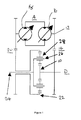
- Figure 1 shows a schematic of a transmission system according to an embodiment of the invention
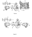
- Figures 2-5 show schematic views of various embodiments of the invention.
- the invention is aimed at providing smooth power and/or torque transfer between a prime mover (e.g. diesel engine, electric motor) and the pump, allowing the assembly to have full power and /or torque available irrespective of the speed.
- a prime mover e.g. diesel engine, electric motor
- the basic structure of a system according to the invention based on a single split input that uses an epicylic gear train as differential mechanism, one differential output being used to drive the pump and the second differential output being connected to a speed regulating mechanism (the auxiliary drive) such that this second output is in effect an input and the differential acts to combine the two inputs rather than to split a single input into two outputs.
- the main input drive diesel engine or electric motor
- the main input drive can be allowed to run at constant speed at the maximum torque speed and drive the pump from 0 rpm to maximum without the need of step gears. This allows the unit to start from standstill and gradually increase the pump speed to the desired operation speed without any slippage or gear changes and maintaining the primary drive at a constant speed.
- a suitable epicylic gear train mechanism consists of a sun gear, a planetary gear, a ring gear and two or more carriers that constrain the planetary gear.
- the epicylic gear system is used as reduction or step gear.
- input or output is given at this constraint point.
- the differential gear is made by splitting or combining input and output.
- Figure 1 shows a schematic of a transmission system according to an embodiment of the invention for use in driving a fracturing pump in an oil well stimulation operation.
- Drive from the prime mover D diesel engine
- Drive is also lead from the prime mover D to the input end 12 of an auxiliary drive system A via suitable connection 14.
- the auxiliary drive A in the embodiment of Figure 1 is an HST (hydraulic pump/motor), the input drive 12 from the prime mover D being used to drive the HST pump 16 which in turn is used to drive the HST motor 18 in the usual manner.
- the output end of the auxiliary drive A is provided with a drive connection 20 which is in turn lead to the ring gear 22 of the epicyclic transmission system.
- the output shaft 24 is connected to the carrier 26 of the planet gear 28 in the epicylic transmission system.
- the output shaft is connected to the fracturing pump P.
- the auxiliary drive A is acting as a continuously variable input to the epicylic differential.
- a part of the output from the prime mover can be applied to the ring gear of the transmission system to determine the final drive ratio applied to the pump P.
- speed control of the output shaft 24 is effected by controlling the speed and direction of the auxiliary drive A while the prime mover speed can remain effectively constant.
- Figure 2 shows schematically the arrangement of Figure 1 in which the prime mover D is connected to the sun gear 10, the auxiliary drive A (in this case constituted by HST H1 which is powered from the prime mover D) is connected to the ring gear 22 and the pump shaft P is connected to the planet gear carrier 26.
- Figure 3 shows a variation of this embodiment wherein the drive to the sun gear 10 is provided by a further HST H2, also powered by the prime mover (not shown).
- Figure 4 shows a different configuration in which the prime mover D is connected to the sun gear 10, the auxiliary drive A (constituted by HST H1 which is powered from the prime mover D) is connected to the planet gear carrier 26 and the pump shaft P is connected to the ring gear 22.
- Figure 5 shows the corresponding arrangement with two HSTs (HST1 and HST2) in pace of the arrangement of the prime mover D and auxiliary HST1 of Figure 4 (cf Figure 3).
- HST of the auxiliary (or main) drive can be replaced by another form of CVT.
- One particularly preferred variation is to provide a torque converter at the prime mover end to improve its characteristics on start-up and shutdown and during major changes of speed and torque delivery.
Landscapes
- Engineering & Computer Science (AREA)
- General Engineering & Computer Science (AREA)
- Mechanical Engineering (AREA)
- Chemical & Material Sciences (AREA)
- Combustion & Propulsion (AREA)
- Structure Of Transmissions (AREA)
- Rotary Pumps (AREA)
- Details And Applications Of Rotary Liquid Pumps (AREA)
- Supply Devices, Intensifiers, Converters, And Telemotors (AREA)
- Fluid-Pressure Circuits (AREA)
- Other Liquid Machine Or Engine Such As Wave Power Use (AREA)
Abstract
Description
- The present invention relates to transmission systems for taking drive from a prime mover to an operating unit. In particular, the invention related to such a transmission for use in driving pump, especially pumps of the type used in the oil and gas exploration and production industries for fracturing and cementing operations.
- During hydraulic fracturing pumping operations on oil or gas wells it is often necessary to pump fluids downhole from the surface at high pressures and flow rates. Depending on the well and the particular operation being performed, it may be necessary to provide in excess of 12000 HP to overcome the downhole pressure at the desired volumetric rate.
- In a typical fracturing pump setup, several pumps are used, each typically being fitted with a diesel engine as primary driver for a high pressure triplex or quintuplex positive displacement pump, coupled through a five to seven speed transmission. Each pump typically delivers between 1500 to 2000 HP depending on the type and size of the engine fitted. Large fracturing operations can require more than 16 pumping units to be available at the well site to meet the pumping power requirements and provide backup in case of failure of individual units.
- Due to the nature of the wells it is often necessary to start the pumping operation against an existing well pressure. This is known to put a high stress on the pump transmission and occasionally cause failure.
- In the event that an active pump fails during the operation, a stand-by unit is required to take its place. In this case the stand-by pump will need to start against a high pressure from standstill. In order to do this, operators must put the engine at speed and engage the desired gear. The transmissions typically used are fitted with a torque converter that allows a limited amount of slip between engine speed and pump speed. However the unit will only tolerate running with such internal slippage for a very limited amount of time.
- An increase is sometimes required to the overall pumping volumetric rate. In most cases this can only be done by changing gears on the transmission of some of the pumps, or starting other pumps.
- All of the above operations place a great strain on the transmission systems, pumps and engines which can lead to unreliability and reduced operational life.
- Conventional cementing or fracturing pump units are typically provided with a five-gear automatic transmission to allow either the full pump flow capacity or the full pump input torque. The weakness of this system is that for pumping under pressure, the engine must be at peak torque speed when the transmission is shifting up or down damaging the transmission disks.
- An alternative to this type of transmission is a conventional hydrostatic transmission (HST) comprising a variable volume pump drive by the engine and a hydraulic motor drive by this pump. Such systems provide a gearless drive mechanism that translates engine power to hydraulic power continuously. Such systems are widely applied in construction machinery, because of their superior speed changeability. However HST does have certain problems that make is unsuitable for pumping systems, e.g. limited low speed / torque range and narrow shift range.
- HST is one form of a continuously variable transmission (CVT). A CVT avoids some of the problems of changing gears in a conventional automatic gear box by allowing any ratio of input and output to be obtained. Mechanical CVTs are well known in automotive applications.
- An extension to CVT design, sometimes known as the Infinitely Variable Transmission (IVT), allows the transmission to drive a vehicle backwards as well as forwards. Transmission input is split into two shafts with one connected to an epicyclic gear set and the other to a CVT. The output from the CVT is connected to a different set of gears in the epicyclic. The gear that does not draw power from engine or CVT transfers torque to the transmission output. The epicyclic gear set acts as a mechanical adding machine to subtract or add one speed from the other.
- Hybrid automobiles also use epicylic gear system to allow both power sources to be connected to the vehicle transmission.
- An object of this invention is to provide a transmission system that has the advantages of a CVT in a form that can be used effectively in a pump drive system. This object is achieved in the invention by the use of a epicylic gear system.
- One aspect of the invention comprises a transmission system for use in a pump system comprising a prime mover driving a pump, the transmission system comprising:
- an epicylic gear system comprising a sun gear and a ring gear, and a planet gear engaged between the sun gear and ring gear;
- a main input drive arranged to be driven by the prime mover;
- an auxiliary input drive arranged to be driven by the prime mover; and
- an output drive arranged to drive the pump;
- (i) the auxiliary input drive is connected to the ring gear and the output drive is lead from the planet gear; or
- (ii) the auxiliary input drive is connected to the planet gear and the output drive is lead from the ring gear.
- By connecting the main and auxiliary input drives in this manner, the epicylic gear system acts to mechanically add or subtract the two drives and so provide any input:output ratio according to the speed and direction of each drive. Changes to the ratio can be made without any harsh physical shocks on either the transmission system, prime mover or pump.
- The planet gear typically comprises a number of gears mounted on a carrier, the auxiliary input drive or the output drive being connected to the carrier.
- Preferably, the auxiliary input drive can operate in forward or reverse directions.
- Another aspect of the invention comprises a pump system comprising a prime mover arranged to drive a pump via a transmission system according to the previous aspect of the invention.
- The main and auxiliary input drives can be mechanical or hydraulic.
- It is preferred that a torque converter is provided between the prime mover and the transmission system.
- The pump is preferably a pump such as a triplex or quintuplex pump for use fracturing, cementing or coil tubing operations in oil wells.
- Figure 1 shows a schematic of a transmission system according to an embodiment of the invention; and
Figures 2-5 show schematic views of various embodiments of the invention. - The invention is aimed at providing smooth power and/or torque transfer between a prime mover (e.g. diesel engine, electric motor) and the pump, allowing the assembly to have full power and /or torque available irrespective of the speed.
- The basic structure of a system according to the invention based on a single split input that uses an epicylic gear train as differential mechanism, one differential output being used to drive the pump and the second differential output being connected to a speed regulating mechanism (the auxiliary drive) such that this second output is in effect an input and the differential acts to combine the two inputs rather than to split a single input into two outputs. Thus the main input drive (diesel engine or electric motor) can be allowed to run at constant speed at the maximum torque speed and drive the pump from 0 rpm to maximum without the need of step gears. This allows the unit to start from standstill and gradually increase the pump speed to the desired operation speed without any slippage or gear changes and maintaining the primary drive at a constant speed.
- A suitable epicylic gear train mechanism consists of a sun gear, a planetary gear, a ring gear and two or more carriers that constrain the planetary gear. In conventional operation of epicylic gear systems, by selecting any two components as, input and output from sun, ring gear and planet gear carrier, and constraining remaining one component, the epicylic gear system is used as reduction or step gear. In the system according to the invention, input or output is given at this constraint point. The differential gear is made by splitting or combining input and output.
- Figure 1 shows a schematic of a transmission system according to an embodiment of the invention for use in driving a fracturing pump in an oil well stimulation operation. Drive from the prime mover D (diesel engine) is lead to the
sun gear 10 of the epicylic transmission system. Drive is also lead from the prime mover D to theinput end 12 of an auxiliary drive system A via suitable connection 14. - The auxiliary drive A in the embodiment of Figure 1 is an HST (hydraulic pump/motor), the input drive 12 from the prime mover D being used to drive the
HST pump 16 which in turn is used to drive the HST motor 18 in the usual manner. The output end of the auxiliary drive A is provided with a drive connection 20 which is in turn lead to thering gear 22 of the epicyclic transmission system. - The
output shaft 24 is connected to thecarrier 26 of theplanet gear 28 in the epicylic transmission system. The output shaft is connected to the fracturing pump P. - In this embodiment, the auxiliary drive A is acting as a continuously variable input to the epicylic differential. By controlling the auxiliary drive A, a part of the output from the prime mover can be applied to the ring gear of the transmission system to determine the final drive ratio applied to the pump P. Thus speed control of the
output shaft 24 is effected by controlling the speed and direction of the auxiliary drive A while the prime mover speed can remain effectively constant. - Various changes can be made to this embodiment. Figure 2 shows schematically the arrangement of Figure 1 in which the prime mover D is connected to the
sun gear 10, the auxiliary drive A (in this case constituted by HST H1 which is powered from the prime mover D) is connected to thering gear 22 and the pump shaft P is connected to theplanet gear carrier 26. Figure 3 shows a variation of this embodiment wherein the drive to thesun gear 10 is provided by a further HST H2, also powered by the prime mover (not shown). Figure 4 shows a different configuration in which the prime mover D is connected to thesun gear 10, the auxiliary drive A (constituted by HST H1 which is powered from the prime mover D) is connected to theplanet gear carrier 26 and the pump shaft P is connected to thering gear 22. Figure 5 shows the corresponding arrangement with two HSTs (HST1 and HST2) in pace of the arrangement of the prime mover D and auxiliary HST1 of Figure 4 (cf Figure 3). In another variation, the HST of the auxiliary (or main) drive can be replaced by another form of CVT. - One particularly preferred variation is to provide a torque converter at the prime mover end to improve its characteristics on start-up and shutdown and during major changes of speed and torque delivery.
- Other changes can be made while remaining within the scope of the invention.
Claims (8)
- A transmission system for use in a pump system comprising a prime mover driving a pump, the transmission system comprising:- an epicylic gear system comprising a sun gear and a ring gear, and a planet gear engaged between the sun gear and ring gear;- a main input drive arranged to be driven by the prime mover;- an auxiliary input drive arranged to be driven by the prime mover; and- an output drive arranged to drive the pump;wherein the main input drive is connected to the sun gear and either(i) the auxiliary input drive is connected to the ring gear and the output drive is lead from the planet gear;
or(ii) the auxiliary input drive is connected to the planet gear and the output drive is lead from the ring gear. - A transmission system as claimed in claim 1, wherein the planet gear comprises a number of gears mounted on a carrier, the auxiliary input drive or the output drive being connected to the carrier.
- A transmission system as claimed in claim 1 or 2, wherein the auxiliary input drive can operate in forward or reverse directions.
- A pump system comprising a prime mover arranged to drive a pump via a transmission system as claimed in any of claim 1, 2 or 3.
- A pump system as claimed in claim 4, wherein the main and auxiliary input drives are mechanical or hydraulic.
- A pump system as claimed in claim 4 or 5, further comprising a torque converter provided between the prime mover and the transmission system.
- A pump system as claimed in claim 4, 5 or 6, wherein the pump is a fracturing pump for use in oil well operations.
- A pump system as claimed in claim 7, wherein the pump is a triplex or quintuplex pump.
Priority Applications (7)
| Application Number | Priority Date | Filing Date | Title |
|---|---|---|---|
| DE602006015054T DE602006015054D1 (en) | 2006-09-13 | 2006-09-13 | Hydraulic fracturing procedure and fracturing pump device |
| EP06291449A EP1900973B1 (en) | 2006-09-13 | 2006-09-13 | Method of performing hydraulic fracturing and fracturing pump system |
| AT06291449T ATE472040T1 (en) | 2006-09-13 | 2006-09-13 | HYDRAULIC FRACTURING METHOD AND FRACTURING PUMP APPARATUS |
| SG200706292-0A SG141327A1 (en) | 2006-09-13 | 2007-08-28 | Transmission system for pump drive |
| US11/849,470 US7901314B2 (en) | 2006-09-13 | 2007-09-04 | Transmission system for pump drive |
| EA200701720A EA011575B1 (en) | 2006-09-13 | 2007-09-12 | A transmission system for pump drive |
| CN200710164877.4A CN101255907B (en) | 2006-09-13 | 2007-09-13 | Transmission system for pump drive |
Applications Claiming Priority (1)
| Application Number | Priority Date | Filing Date | Title |
|---|---|---|---|
| EP06291449A EP1900973B1 (en) | 2006-09-13 | 2006-09-13 | Method of performing hydraulic fracturing and fracturing pump system |
Publications (2)
| Publication Number | Publication Date |
|---|---|
| EP1900973A1 true EP1900973A1 (en) | 2008-03-19 |
| EP1900973B1 EP1900973B1 (en) | 2010-06-23 |
Family
ID=37670995
Family Applications (1)
| Application Number | Title | Priority Date | Filing Date |
|---|---|---|---|
| EP06291449A Not-in-force EP1900973B1 (en) | 2006-09-13 | 2006-09-13 | Method of performing hydraulic fracturing and fracturing pump system |
Country Status (7)
| Country | Link |
|---|---|
| US (1) | US7901314B2 (en) |
| EP (1) | EP1900973B1 (en) |
| CN (1) | CN101255907B (en) |
| AT (1) | ATE472040T1 (en) |
| DE (1) | DE602006015054D1 (en) |
| EA (1) | EA011575B1 (en) |
| SG (1) | SG141327A1 (en) |
Cited By (5)
| Publication number | Priority date | Publication date | Assignee | Title |
|---|---|---|---|---|
| CN102575751A (en) * | 2009-09-10 | 2012-07-11 | Gea机械设备意大利股份公司 | High-pressure homogenizer with an epicyclic reduction gear unit |
| WO2013007247A1 (en) * | 2011-07-08 | 2013-01-17 | Ixetic Bad Homburg Gmbh | Pump drive |
| CN103244620A (en) * | 2013-05-21 | 2013-08-14 | 江苏圣乐机械有限公司 | Mechanical reversing speed reducer and vertical type pumping unit |
| WO2014007940A1 (en) * | 2012-07-05 | 2014-01-09 | General Electric Company | System and method for powering a hydraulic pump |
| US12209490B2 (en) | 2012-11-16 | 2025-01-28 | U.S. Well Services, LLC | System for pumping hydraulic fracturing fluid using electric pumps |
Families Citing this family (63)
| Publication number | Priority date | Publication date | Assignee | Title |
|---|---|---|---|---|
| DE102004061034A1 (en) * | 2004-12-18 | 2006-06-22 | Daimlerchrysler Ag | Method for monitoring a transmission oil pump |
| US8622859B2 (en) * | 2009-06-10 | 2014-01-07 | Czero Holding Company, Llc | Systems and methods for hybridization of a motor vehicle using hydraulic components |
| DE102009031382A1 (en) * | 2009-07-01 | 2011-01-05 | Robert Bosch Gmbh | Drive system and method for changing driving ranges of the drive system |
| USRE46725E1 (en) | 2009-09-11 | 2018-02-20 | Halliburton Energy Services, Inc. | Electric or natural gas fired small footprint fracturing fluid blending and pumping equipment |
| US9085225B2 (en) * | 2012-01-23 | 2015-07-21 | Dennis Ray Halwes | Infinitely variable transmission |
| US9840897B2 (en) | 2012-03-27 | 2017-12-12 | Kevin Larson | Hydraulic fracturing system and method |
| US20130306322A1 (en) | 2012-05-21 | 2013-11-21 | General Electric Company | System and process for extracting oil and gas by hydraulic fracturing |
| US10020711B2 (en) | 2012-11-16 | 2018-07-10 | U.S. Well Services, LLC | System for fueling electric powered hydraulic fracturing equipment with multiple fuel sources |
| US10119381B2 (en) | 2012-11-16 | 2018-11-06 | U.S. Well Services, LLC | System for reducing vibrations in a pressure pumping fleet |
| US10378335B2 (en) | 2013-03-13 | 2019-08-13 | Schlumberger Technology Corporation | Pressure testing of well servicing systems |
| SG11201507126QA (en) * | 2013-03-13 | 2015-10-29 | Schlumberger Technology Bv | Pressure testing of well servicing systems |
| DE102013204747A1 (en) * | 2013-03-19 | 2014-09-25 | Zf Friedrichshafen Ag | Transmission device with secondary coupled power split |
| US9091267B2 (en) | 2013-07-08 | 2015-07-28 | Caterpillar Inc. | Controller for varying flow rate from fixed displacement pump |
| US10670124B2 (en) | 2013-12-31 | 2020-06-02 | Deere & Company | Multi-mode infinitely variable transmission |
| US10655710B2 (en) | 2013-12-31 | 2020-05-19 | Deere & Company | Multi-mode infinitely variable transmission that provides seamless shifting |
| US9944163B2 (en) * | 2014-04-09 | 2018-04-17 | Deere & Company | Multi-mode power trains |
| US10738868B2 (en) | 2014-04-09 | 2020-08-11 | Deere & Company | Multi-mode powertrains |
| US10647193B2 (en) | 2014-04-09 | 2020-05-12 | Deere & Company | Multi-mode power trains |
| DE102014211964A1 (en) * | 2014-06-23 | 2015-12-24 | Voith Patent Gmbh | pumping device |
| US9638194B2 (en) | 2015-01-02 | 2017-05-02 | General Electric Company | System and method for power management of pumping system |
| US10221856B2 (en) | 2015-08-18 | 2019-03-05 | Bj Services, Llc | Pump system and method of starting pump |
| CN106609820A (en) * | 2015-10-27 | 2017-05-03 | 熵零股份有限公司 | Energy adjustment system |
| CN106608183A (en) * | 2015-10-27 | 2017-05-03 | 熵零股份有限公司 | Fluid and machine hybrid drive vehicle |
| CN105240481A (en) * | 2015-11-18 | 2016-01-13 | 山东农业大学 | Hydraulic mechanical stepless transmission of high-power tractor |
| US12078110B2 (en) | 2015-11-20 | 2024-09-03 | Us Well Services, Llc | System for gas compression on electric hydraulic fracturing fleets |
| CN108700165B (en) | 2016-01-19 | 2022-04-26 | 双环公司 | Heavy industrial transmission |
| DE102016212209A1 (en) * | 2016-07-05 | 2018-01-11 | Zf Friedrichshafen Ag | PTO arrangement |
| CN106545637A (en) * | 2016-10-31 | 2017-03-29 | 广西柳工机械股份有限公司 | Power distributes regulating system and loading machine dynamical system |
| US10563649B2 (en) * | 2017-04-06 | 2020-02-18 | Caterpillar Inc. | Hydraulic fracturing system and method for optimizing operation thereof |
| US10619711B2 (en) | 2017-04-12 | 2020-04-14 | Deere & Company | Infinitely variable transmission with power reverser |
| US10415348B2 (en) * | 2017-05-02 | 2019-09-17 | Caterpillar Inc. | Multi-rig hydraulic fracturing system and method for optimizing operation thereof |
| NO20171100A1 (en) * | 2017-07-04 | 2019-01-07 | Rsm Imagineering As | A dual-acting pressure boosting liquid partition device, system, fleet and use |
| IT201700049551A1 (en) * | 2017-07-10 | 2019-01-10 | Luciano Valotto | Mechanism with accumulation flywheel, for potential energy generator at one or more stations, with torque control. |
| CA3073853C (en) | 2017-09-25 | 2023-02-28 | St9 Gas And Oil, Llc | Electric drive pump for well stimulation |
| CN108006188B (en) * | 2017-12-27 | 2020-06-26 | 北京理工大学 | Double-speed hydraulic hybrid power driving system |
| CN108607181A (en) * | 2018-04-02 | 2018-10-02 | 江苏卡威专用汽车制造有限公司 | A kind of drive system of fire fighting truck |
| CN108374875A (en) * | 2018-04-25 | 2018-08-07 | 同济大学 | A kind of frequency conversion change displacement machine hydraulic stepless speed change transmission system |
| US11052747B2 (en) | 2018-05-04 | 2021-07-06 | Deere & Company | Multi-mode powertrains |
| US11091018B2 (en) | 2018-05-11 | 2021-08-17 | Deere & Company | Powertrain with variable vertical drop distance |
| RU185446U1 (en) * | 2018-08-20 | 2018-12-05 | Общество с ограниченной ответственностью "КОМ" | TRANSMISSION |
| US10914155B2 (en) | 2018-10-09 | 2021-02-09 | U.S. Well Services, LLC | Electric powered hydraulic fracturing pump system with single electric powered multi-plunger pump fracturing trailers, filtration units, and slide out platform |
| CN109578544B (en) * | 2018-12-18 | 2021-04-27 | 河南科技大学 | Single-planet-row multi-mode hydraulic mechanical stepless speed changer |
| US10975959B2 (en) | 2019-04-01 | 2021-04-13 | Deere & Company | Transmission clutch braking control system |
| EP3956542B1 (en) | 2019-04-17 | 2024-11-20 | Twin Disc, Inc. | Electro-hydraulic high-pressure oilfield pumping system |
| WO2020231483A1 (en) | 2019-05-13 | 2020-11-19 | U.S. Well Services, LLC | Encoderless vector control for vfd in hydraulic fracturing applications |
| WO2021022048A1 (en) | 2019-08-01 | 2021-02-04 | U.S. Well Services, LLC | High capacity power storage system for electric hydraulic fracturing |
| US11137052B2 (en) | 2019-08-29 | 2021-10-05 | Deere & Company | Transmission assembly with integrated CVP |
| US12074553B2 (en) | 2019-10-23 | 2024-08-27 | Schlumberger Technology Corporation | System and method for stopping electrically powered fracturing pumps |
| US11351983B2 (en) | 2019-10-31 | 2022-06-07 | Deere & Company | Power control system with transmission transient boost function |
| JP7211928B2 (en) * | 2019-12-04 | 2023-01-24 | 株式会社クボタ | multipurpose vehicle |
| US11846085B2 (en) | 2020-02-17 | 2023-12-19 | Deere & Company | Energy management system for a hybrid vehicle with an electrically powered hydraulic system |
| EP4168650B1 (en) * | 2020-06-22 | 2026-04-29 | Twin Disc, Inc. | Oilfield pressure pumping system with slow speed and high pressure fracturing fluid output |
| US11754060B2 (en) | 2020-09-01 | 2023-09-12 | Fmc Technologies, Inc. | Hydraulic fracturing pump system |
| US11325459B2 (en) | 2020-10-09 | 2022-05-10 | Deere & Company | Low profile transmission assembly with integrated CVP |
| US11613246B2 (en) | 2021-01-21 | 2023-03-28 | Deere & Company | Power control system with engine throttle shift function |
| CN112747090B (en) * | 2021-01-25 | 2023-04-14 | 重庆胜特佳机械有限公司 | Dual-power multi-mode continuously variable speed coupling output mechanism |
| US11628822B2 (en) | 2021-02-09 | 2023-04-18 | Deere & Company | Power control system with stall prevention clutch modulation function |
| US11299141B1 (en) | 2021-02-10 | 2022-04-12 | Deere & Company | System for multi-layer braking and retardation in a work vehicle |
| US11820361B2 (en) | 2021-11-30 | 2023-11-21 | Deere & Company | Transmission assembly with electrical machine unit for improved shift quality |
| US11585412B1 (en) | 2021-12-22 | 2023-02-21 | Deere & Company | Electronically-variable, dual-path power shift transmission for work vehicles |
| US11607948B1 (en) | 2021-12-22 | 2023-03-21 | Deere & Company | Electronically-variable power shift transmission for work vehicles |
| US12313057B2 (en) | 2022-02-11 | 2025-05-27 | Spm Oil & Gas Inc. | Optimizing an efficiency of a positive displacement pump with a constant or near-constant speed power source |
| US11913528B1 (en) | 2022-10-28 | 2024-02-27 | Deere & Company | Multi-mode continuously variable transmission assembly with drop set arrangement |
Citations (11)
| Publication number | Priority date | Publication date | Assignee | Title |
|---|---|---|---|---|
| US4066123A (en) * | 1976-12-23 | 1978-01-03 | Standard Oil Company (Indiana) | Hydraulic pumping unit with a variable speed triplex pump |
| FR2482692A1 (en) * | 1980-05-14 | 1981-11-20 | Renault Vehicules Ind | Two speed transmission for bus - has torque converter in line with four-shaft differential gear box of which two shafts are coupled to variable capacity motors |
| US4311066A (en) | 1979-01-12 | 1982-01-19 | Mannesmann Aktiengesellschaft | Reduction gear and speed control for dredge pumps |
| EP0059055A2 (en) * | 1981-02-21 | 1982-09-01 | Julián PARRAGA GARCIA | Continuous, high-performance hydromechanical speed gear |
| JPS5846246A (en) * | 1981-09-16 | 1983-03-17 | Ishikawajima Harima Heavy Ind Co Ltd | Continuously variable transmission |
| DE3812412A1 (en) * | 1988-04-14 | 1989-10-26 | Walter Schopf | Pump drive for fixed displacement pumps with mobile drive |
| US5092824A (en) * | 1990-10-09 | 1992-03-03 | Connett Donald C | Pump output control system with high efficiency hydromechanical variable speed drive |
| EP0485094A1 (en) * | 1990-11-07 | 1992-05-13 | Doyle Transmissions Limited | A variable speed transmission assembly |
| JP2002202084A (en) * | 2000-12-28 | 2002-07-19 | Ishikawajima Harima Heavy Ind Co Ltd | Impeller variable speed pump |
| JP2002202083A (en) * | 2000-12-28 | 2002-07-19 | Ishikawajima Harima Heavy Ind Co Ltd | Impeller variable speed pump |
| JP2005016476A (en) * | 2003-06-27 | 2005-01-20 | Ebara Corp | Vertical shaft pump |
Family Cites Families (24)
| Publication number | Priority date | Publication date | Assignee | Title |
|---|---|---|---|---|
| GB1062631A (en) * | 1963-01-11 | 1967-03-22 | Plessey Uk Ltd | Improvements in or relating to composite hydromechanical constant-speed drives |
| US3383952A (en) * | 1965-02-01 | 1968-05-21 | Gen Motors Corp | Hydrostatic-mechanical vehicle drive |
| US3534631A (en) * | 1968-08-16 | 1970-10-20 | Arthur B Keller | Infinitely variable ratio constant mesh gearing system |
| US3665788A (en) * | 1970-08-19 | 1972-05-30 | Sundstrand Corp | Hydromechanical storing transmission |
| US3714846A (en) * | 1971-02-23 | 1973-02-06 | Sundstrand Corp | Hydrostatic-differential transmission |
| DE2460098C3 (en) * | 1974-12-19 | 1982-06-16 | Gewerkschaft Eisenhütte Westfalia, 4670 Lünen | Electric chain drive for planing systems, chain conveyor and the like. |
| GB1582430A (en) * | 1976-12-22 | 1981-01-07 | Secr Defence | Variable ratio transmission systems |
| DE2758660A1 (en) * | 1977-12-29 | 1979-07-05 | Zahnradfabrik Friedrichshafen | CONTINUOUSLY VARIABLE TRANSMISSION WITH POWER SHARING |
| US4489623A (en) * | 1982-05-03 | 1984-12-25 | Caterpillar Tractor Co. | Axle shaft and pump drive mechanism |
| US4774855A (en) * | 1982-08-17 | 1988-10-04 | Vickers Shipbuilding And Engineering Limited | Apparatus for providing an electrical generator with a constant rotational speed from a variable speed input |
| SU1273670A1 (en) * | 1984-07-22 | 1986-11-30 | Ленинградский Институт Водного Транспорта | Hydromechanical transmission |
| US4721439A (en) * | 1984-11-16 | 1988-01-26 | Wiwa Wilhelm Wagner Gmbh & Co. Kg | Piston pump and drive therefor |
| SU1272040A1 (en) * | 1984-12-24 | 1986-11-23 | Предприятие П/Я Р-6194 | Hydromechanical transmission |
| DE3672296D1 (en) * | 1986-02-24 | 1990-08-02 | Shimadzu Corp | HYDROMECHANICAL TRANSMISSION. |
| SU1498940A1 (en) * | 1986-05-26 | 1989-08-07 | Азербайджанский научно-исследовательский и проектно-конструкторский институт нефтяного машиностроения | Connecting rod/cam drive for multiplunger pump |
| JP3343660B2 (en) * | 1992-12-10 | 2002-11-11 | 本田技研工業株式会社 | Oil pump drive |
| GB2322420B (en) * | 1997-02-19 | 2000-12-27 | Delphi France Automotive Sys | Automatic transmission |
| AT500431B1 (en) * | 1997-11-25 | 2006-11-15 | Zahnradfabrik Friedrichshafen | HYDROSTATIC-MECHANICAL POWER-LIFTING GEARBOX WITH LARGE SPREAD |
| DE10016435B4 (en) * | 2000-04-01 | 2014-03-13 | Deere & Company | Ventilation device for an agricultural vehicle |
| JP2001329948A (en) * | 2000-05-23 | 2001-11-30 | Nsk Ltd | Pump drive |
| RU2191303C2 (en) * | 2000-11-13 | 2002-10-20 | Открытое акционерное общество "Курганмашзавод" | Hydromechanical transmission |
| RU38828U1 (en) * | 2004-03-02 | 2004-07-10 | Открытое акционерное общество "Строммашина" | INSTALLATION PUMPING MOBILE OIL-FIELD |
| US7252147B2 (en) * | 2004-07-22 | 2007-08-07 | Halliburton Energy Services, Inc. | Cementing methods and systems for initiating fluid flow with reduced pumping pressure |
| US20090041588A1 (en) * | 2007-08-08 | 2009-02-12 | Halliburton Energy Services, Inc. | Active valve system for positive displacement pump |
-
2006
- 2006-09-13 DE DE602006015054T patent/DE602006015054D1/en active Active
- 2006-09-13 EP EP06291449A patent/EP1900973B1/en not_active Not-in-force
- 2006-09-13 AT AT06291449T patent/ATE472040T1/en not_active IP Right Cessation
-
2007
- 2007-08-28 SG SG200706292-0A patent/SG141327A1/en unknown
- 2007-09-04 US US11/849,470 patent/US7901314B2/en not_active Expired - Fee Related
- 2007-09-12 EA EA200701720A patent/EA011575B1/en not_active IP Right Cessation
- 2007-09-13 CN CN200710164877.4A patent/CN101255907B/en not_active Expired - Fee Related
Patent Citations (11)
| Publication number | Priority date | Publication date | Assignee | Title |
|---|---|---|---|---|
| US4066123A (en) * | 1976-12-23 | 1978-01-03 | Standard Oil Company (Indiana) | Hydraulic pumping unit with a variable speed triplex pump |
| US4311066A (en) | 1979-01-12 | 1982-01-19 | Mannesmann Aktiengesellschaft | Reduction gear and speed control for dredge pumps |
| FR2482692A1 (en) * | 1980-05-14 | 1981-11-20 | Renault Vehicules Ind | Two speed transmission for bus - has torque converter in line with four-shaft differential gear box of which two shafts are coupled to variable capacity motors |
| EP0059055A2 (en) * | 1981-02-21 | 1982-09-01 | Julián PARRAGA GARCIA | Continuous, high-performance hydromechanical speed gear |
| JPS5846246A (en) * | 1981-09-16 | 1983-03-17 | Ishikawajima Harima Heavy Ind Co Ltd | Continuously variable transmission |
| DE3812412A1 (en) * | 1988-04-14 | 1989-10-26 | Walter Schopf | Pump drive for fixed displacement pumps with mobile drive |
| US5092824A (en) * | 1990-10-09 | 1992-03-03 | Connett Donald C | Pump output control system with high efficiency hydromechanical variable speed drive |
| EP0485094A1 (en) * | 1990-11-07 | 1992-05-13 | Doyle Transmissions Limited | A variable speed transmission assembly |
| JP2002202084A (en) * | 2000-12-28 | 2002-07-19 | Ishikawajima Harima Heavy Ind Co Ltd | Impeller variable speed pump |
| JP2002202083A (en) * | 2000-12-28 | 2002-07-19 | Ishikawajima Harima Heavy Ind Co Ltd | Impeller variable speed pump |
| JP2005016476A (en) * | 2003-06-27 | 2005-01-20 | Ebara Corp | Vertical shaft pump |
Non-Patent Citations (4)
| Title |
|---|
| ASME-PAPER 69-PET-24 1969, 1969 * |
| DATABASE COMPENDEX [online] ENGINEERING INFORMATION, INC., NEW YORK, NY, US; EAGER V ET AL: "DEVELOPMENT OF A QUINTUPLEX MOBILE SERVICE PUMP", XP008074437, Database accession no. EIX70060062593 * |
| DATABASE COMPENDEX [online] ENGINEERING INFORMATION, INC., NEW YORK, NY, US; WADMAN B W: "2000 HP gas turbine fracturing rig", XP008074468, Database accession no. EIX19670030505 * |
| DIESEL GAS TURBINE PROGRESS; DIESEL AND GAS TURBINE PROGRESS AUG 1966 MILWAUKEE, WI, UNITED STATES, vol. 32, no. 8, August 1966 (1966-08-01), pages 36 - 37 * |
Cited By (8)
| Publication number | Priority date | Publication date | Assignee | Title |
|---|---|---|---|---|
| CN102575751A (en) * | 2009-09-10 | 2012-07-11 | Gea机械设备意大利股份公司 | High-pressure homogenizer with an epicyclic reduction gear unit |
| CN102575751B (en) * | 2009-09-10 | 2015-03-25 | Gea机械设备意大利股份公司 | High-pressure homogenizer with an epicyclic reduction gear unit |
| WO2013007247A1 (en) * | 2011-07-08 | 2013-01-17 | Ixetic Bad Homburg Gmbh | Pump drive |
| WO2014007940A1 (en) * | 2012-07-05 | 2014-01-09 | General Electric Company | System and method for powering a hydraulic pump |
| US8997904B2 (en) | 2012-07-05 | 2015-04-07 | General Electric Company | System and method for powering a hydraulic pump |
| US12209490B2 (en) | 2012-11-16 | 2025-01-28 | U.S. Well Services, LLC | System for pumping hydraulic fracturing fluid using electric pumps |
| CN103244620A (en) * | 2013-05-21 | 2013-08-14 | 江苏圣乐机械有限公司 | Mechanical reversing speed reducer and vertical type pumping unit |
| CN103244620B (en) * | 2013-05-21 | 2014-07-02 | 江苏圣乐机械有限公司 | Mechanical reversing reducer and vertical pumping unit |
Also Published As
| Publication number | Publication date |
|---|---|
| EA200701720A1 (en) | 2008-04-28 |
| CN101255907B (en) | 2013-10-02 |
| SG141327A1 (en) | 2008-04-28 |
| ATE472040T1 (en) | 2010-07-15 |
| US7901314B2 (en) | 2011-03-08 |
| CN101255907A (en) | 2008-09-03 |
| EA011575B1 (en) | 2009-04-28 |
| DE602006015054D1 (en) | 2010-08-05 |
| US20080182699A1 (en) | 2008-07-31 |
| EP1900973B1 (en) | 2010-06-23 |
Similar Documents
| Publication | Publication Date | Title |
|---|---|---|
| EP1900973B1 (en) | Method of performing hydraulic fracturing and fracturing pump system | |
| CN109890675B (en) | Dual input pump and system | |
| US8696509B2 (en) | Power split transmission | |
| CN102011767B (en) | Hydraulic system | |
| US8961347B2 (en) | Cold start clutch for CVT transmission | |
| US3709061A (en) | Non-regenerative hydromechanical transmission | |
| US7971434B2 (en) | Device and method for continuously variable transmission of traveling vehicle | |
| CN103758976A (en) | Power transmission system and grader | |
| JPH01279156A (en) | Device for controlling hydraulic pressure of change gear | |
| US20210396121A1 (en) | Oilfield Pressure Pumping System With Slow Speed And High Pressure Fracturing Fluid Output | |
| EP2118523B1 (en) | Method for controlling two variable displacement hydrostatic units in an infinitely variable hydro-mechanical transmission | |
| CN201599379U (en) | Hydrodynamic drive gearbox | |
| DK2860426T3 (en) | Hydromechanical transmission | |
| JP2893757B2 (en) | Transmission hydraulic control device | |
| US6527660B1 (en) | Method and apparatus to transfer torque at a nominally constant speed to a dynamoelectric machine from a variable speed engine | |
| CN105317992B (en) | Hydraulic pressure control device | |
| KR101497091B1 (en) | Continuously variable transmission of tractor with simple structure | |
| US20190011046A1 (en) | Hydraulic circuit to enable unidirectional flow under forward and reverse positive displacement pump rotation | |
| US7299891B2 (en) | Hydraulic drive mechanism for mobile vehicles | |
| JP4284024B2 (en) | Small engine transmission | |
| CN107407410A (en) | Multi-pressure hydraulic control system for dual-clutch automatic transmission | |
| CN112377592A (en) | Single-stage planetary gear return flow type hydraulic mechanical stepless transmission system | |
| CN101443578B (en) | Low noise gear pump | |
| CN119196267A (en) | A hydraulic return type three-speed automatic transmission for bulldozers | |
| CN110469648A (en) | A new type of low-speed working hydraulic transmission and its control realization method |
Legal Events
| Date | Code | Title | Description |
|---|---|---|---|
| PUAI | Public reference made under article 153(3) epc to a published international application that has entered the european phase |
Free format text: ORIGINAL CODE: 0009012 |
|
| AK | Designated contracting states |
Kind code of ref document: A1 Designated state(s): AT BE BG CH CY CZ DE DK EE ES FI FR GB GR HU IE IS IT LI LT LU LV MC NL PL PT RO SE SI SK TR |
|
| AX | Request for extension of the european patent |
Extension state: AL BA HR MK YU |
|
| 17P | Request for examination filed |
Effective date: 20080718 |
|
| 17Q | First examination report despatched |
Effective date: 20080904 |
|
| AKX | Designation fees paid |
Designated state(s): AT BE BG CH CY CZ DE DK EE ES FI FR GB GR HU IE IS IT LI LT LU LV MC NL PL PT RO SE SI SK TR |
|
| RIC1 | Information provided on ipc code assigned before grant |
Ipc: E21B 43/16 20060101AFI20090812BHEP |
|
| RTI1 | Title (correction) |
Free format text: METHOD OF PERFORMING HYDRAULIC FRACTURING AND FRACTURING PUMP SYSTEM |
|
| GRAP | Despatch of communication of intention to grant a patent |
Free format text: ORIGINAL CODE: EPIDOSNIGR1 |
|
| GRAS | Grant fee paid |
Free format text: ORIGINAL CODE: EPIDOSNIGR3 |
|
| GRAA | (expected) grant |
Free format text: ORIGINAL CODE: 0009210 |
|
| AK | Designated contracting states |
Kind code of ref document: B1 Designated state(s): AT BE BG CH CY CZ DE DK EE ES FI FR GB GR HU IE IS IT LI LT LU LV MC NL PL PT RO SE SI SK TR |
|
| REG | Reference to a national code |
Ref country code: CH Ref legal event code: EP |
|
| REG | Reference to a national code |
Ref country code: IE Ref legal event code: FG4D |
|
| REF | Corresponds to: |
Ref document number: 602006015054 Country of ref document: DE Date of ref document: 20100805 Kind code of ref document: P |
|
| REG | Reference to a national code |
Ref country code: NL Ref legal event code: T3 |
|
| PG25 | Lapsed in a contracting state [announced via postgrant information from national office to epo] |
Ref country code: SE Free format text: LAPSE BECAUSE OF FAILURE TO SUBMIT A TRANSLATION OF THE DESCRIPTION OR TO PAY THE FEE WITHIN THE PRESCRIBED TIME-LIMIT Effective date: 20100623 Ref country code: LT Free format text: LAPSE BECAUSE OF FAILURE TO SUBMIT A TRANSLATION OF THE DESCRIPTION OR TO PAY THE FEE WITHIN THE PRESCRIBED TIME-LIMIT Effective date: 20100623 |
|
| LTIE | Lt: invalidation of european patent or patent extension |
Effective date: 20100623 |
|
| PG25 | Lapsed in a contracting state [announced via postgrant information from national office to epo] |
Ref country code: SI Free format text: LAPSE BECAUSE OF FAILURE TO SUBMIT A TRANSLATION OF THE DESCRIPTION OR TO PAY THE FEE WITHIN THE PRESCRIBED TIME-LIMIT Effective date: 20100623 Ref country code: LV Free format text: LAPSE BECAUSE OF FAILURE TO SUBMIT A TRANSLATION OF THE DESCRIPTION OR TO PAY THE FEE WITHIN THE PRESCRIBED TIME-LIMIT Effective date: 20100623 Ref country code: FI Free format text: LAPSE BECAUSE OF FAILURE TO SUBMIT A TRANSLATION OF THE DESCRIPTION OR TO PAY THE FEE WITHIN THE PRESCRIBED TIME-LIMIT Effective date: 20100623 Ref country code: AT Free format text: LAPSE BECAUSE OF FAILURE TO SUBMIT A TRANSLATION OF THE DESCRIPTION OR TO PAY THE FEE WITHIN THE PRESCRIBED TIME-LIMIT Effective date: 20100623 |
|
| PG25 | Lapsed in a contracting state [announced via postgrant information from national office to epo] |
Ref country code: GR Free format text: LAPSE BECAUSE OF FAILURE TO SUBMIT A TRANSLATION OF THE DESCRIPTION OR TO PAY THE FEE WITHIN THE PRESCRIBED TIME-LIMIT Effective date: 20100924 Ref country code: PL Free format text: LAPSE BECAUSE OF FAILURE TO SUBMIT A TRANSLATION OF THE DESCRIPTION OR TO PAY THE FEE WITHIN THE PRESCRIBED TIME-LIMIT Effective date: 20100623 |
|
| PG25 | Lapsed in a contracting state [announced via postgrant information from national office to epo] |
Ref country code: EE Free format text: LAPSE BECAUSE OF FAILURE TO SUBMIT A TRANSLATION OF THE DESCRIPTION OR TO PAY THE FEE WITHIN THE PRESCRIBED TIME-LIMIT Effective date: 20100623 |
|
| PG25 | Lapsed in a contracting state [announced via postgrant information from national office to epo] |
Ref country code: IS Free format text: LAPSE BECAUSE OF FAILURE TO SUBMIT A TRANSLATION OF THE DESCRIPTION OR TO PAY THE FEE WITHIN THE PRESCRIBED TIME-LIMIT Effective date: 20101023 Ref country code: CZ Free format text: LAPSE BECAUSE OF FAILURE TO SUBMIT A TRANSLATION OF THE DESCRIPTION OR TO PAY THE FEE WITHIN THE PRESCRIBED TIME-LIMIT Effective date: 20100623 Ref country code: CY Free format text: LAPSE BECAUSE OF FAILURE TO SUBMIT A TRANSLATION OF THE DESCRIPTION OR TO PAY THE FEE WITHIN THE PRESCRIBED TIME-LIMIT Effective date: 20100623 Ref country code: BE Free format text: LAPSE BECAUSE OF FAILURE TO SUBMIT A TRANSLATION OF THE DESCRIPTION OR TO PAY THE FEE WITHIN THE PRESCRIBED TIME-LIMIT Effective date: 20100623 Ref country code: SK Free format text: LAPSE BECAUSE OF FAILURE TO SUBMIT A TRANSLATION OF THE DESCRIPTION OR TO PAY THE FEE WITHIN THE PRESCRIBED TIME-LIMIT Effective date: 20100623 Ref country code: RO Free format text: LAPSE BECAUSE OF FAILURE TO SUBMIT A TRANSLATION OF THE DESCRIPTION OR TO PAY THE FEE WITHIN THE PRESCRIBED TIME-LIMIT Effective date: 20100623 Ref country code: PT Free format text: LAPSE BECAUSE OF FAILURE TO SUBMIT A TRANSLATION OF THE DESCRIPTION OR TO PAY THE FEE WITHIN THE PRESCRIBED TIME-LIMIT Effective date: 20101025 |
|
| PG25 | Lapsed in a contracting state [announced via postgrant information from national office to epo] |
Ref country code: IT Free format text: LAPSE BECAUSE OF FAILURE TO SUBMIT A TRANSLATION OF THE DESCRIPTION OR TO PAY THE FEE WITHIN THE PRESCRIBED TIME-LIMIT Effective date: 20100623 |
|
| PG25 | Lapsed in a contracting state [announced via postgrant information from national office to epo] |
Ref country code: DK Free format text: LAPSE BECAUSE OF FAILURE TO SUBMIT A TRANSLATION OF THE DESCRIPTION OR TO PAY THE FEE WITHIN THE PRESCRIBED TIME-LIMIT Effective date: 20100623 Ref country code: MC Free format text: LAPSE BECAUSE OF NON-PAYMENT OF DUE FEES Effective date: 20100930 |
|
| PLBE | No opposition filed within time limit |
Free format text: ORIGINAL CODE: 0009261 |
|
| REG | Reference to a national code |
Ref country code: CH Ref legal event code: PL |
|
| STAA | Information on the status of an ep patent application or granted ep patent |
Free format text: STATUS: NO OPPOSITION FILED WITHIN TIME LIMIT |
|
| 26N | No opposition filed |
Effective date: 20110324 |
|
| REG | Reference to a national code |
Ref country code: FR Ref legal event code: ST Effective date: 20110531 |
|
| REG | Reference to a national code |
Ref country code: DE Ref legal event code: R097 Ref document number: 602006015054 Country of ref document: DE Effective date: 20110323 |
|
| PG25 | Lapsed in a contracting state [announced via postgrant information from national office to epo] |
Ref country code: CH Free format text: LAPSE BECAUSE OF NON-PAYMENT OF DUE FEES Effective date: 20100930 Ref country code: IE Free format text: LAPSE BECAUSE OF NON-PAYMENT OF DUE FEES Effective date: 20100913 Ref country code: FR Free format text: LAPSE BECAUSE OF NON-PAYMENT OF DUE FEES Effective date: 20100930 Ref country code: LI Free format text: LAPSE BECAUSE OF NON-PAYMENT OF DUE FEES Effective date: 20100930 |
|
| PG25 | Lapsed in a contracting state [announced via postgrant information from national office to epo] |
Ref country code: HU Free format text: LAPSE BECAUSE OF FAILURE TO SUBMIT A TRANSLATION OF THE DESCRIPTION OR TO PAY THE FEE WITHIN THE PRESCRIBED TIME-LIMIT Effective date: 20101224 Ref country code: BG Free format text: LAPSE BECAUSE OF FAILURE TO SUBMIT A TRANSLATION OF THE DESCRIPTION OR TO PAY THE FEE WITHIN THE PRESCRIBED TIME-LIMIT Effective date: 20100623 Ref country code: LU Free format text: LAPSE BECAUSE OF NON-PAYMENT OF DUE FEES Effective date: 20100913 |
|
| PG25 | Lapsed in a contracting state [announced via postgrant information from national office to epo] |
Ref country code: TR Free format text: LAPSE BECAUSE OF FAILURE TO SUBMIT A TRANSLATION OF THE DESCRIPTION OR TO PAY THE FEE WITHIN THE PRESCRIBED TIME-LIMIT Effective date: 20100623 |
|
| PG25 | Lapsed in a contracting state [announced via postgrant information from national office to epo] |
Ref country code: BG Free format text: LAPSE BECAUSE OF FAILURE TO SUBMIT A TRANSLATION OF THE DESCRIPTION OR TO PAY THE FEE WITHIN THE PRESCRIBED TIME-LIMIT Effective date: 20100923 |
|
| PG25 | Lapsed in a contracting state [announced via postgrant information from national office to epo] |
Ref country code: ES Free format text: LAPSE BECAUSE OF FAILURE TO SUBMIT A TRANSLATION OF THE DESCRIPTION OR TO PAY THE FEE WITHIN THE PRESCRIBED TIME-LIMIT Effective date: 20101004 |
|
| PGFP | Annual fee paid to national office [announced via postgrant information from national office to epo] |
Ref country code: GB Payment date: 20160907 Year of fee payment: 11 Ref country code: DE Payment date: 20160907 Year of fee payment: 11 Ref country code: NL Payment date: 20160913 Year of fee payment: 11 |
|
| REG | Reference to a national code |
Ref country code: DE Ref legal event code: R119 Ref document number: 602006015054 Country of ref document: DE |
|
| REG | Reference to a national code |
Ref country code: NL Ref legal event code: MM Effective date: 20171001 |
|
| GBPC | Gb: european patent ceased through non-payment of renewal fee |
Effective date: 20170913 |
|
| PG25 | Lapsed in a contracting state [announced via postgrant information from national office to epo] |
Ref country code: NL Free format text: LAPSE BECAUSE OF NON-PAYMENT OF DUE FEES Effective date: 20171001 |
|
| PG25 | Lapsed in a contracting state [announced via postgrant information from national office to epo] |
Ref country code: DE Free format text: LAPSE BECAUSE OF NON-PAYMENT OF DUE FEES Effective date: 20180404 Ref country code: GB Free format text: LAPSE BECAUSE OF NON-PAYMENT OF DUE FEES Effective date: 20170913 |