EP1900963A1 - A suspension unit - Google Patents
A suspension unit Download PDFInfo
- Publication number
- EP1900963A1 EP1900963A1 EP06254770A EP06254770A EP1900963A1 EP 1900963 A1 EP1900963 A1 EP 1900963A1 EP 06254770 A EP06254770 A EP 06254770A EP 06254770 A EP06254770 A EP 06254770A EP 1900963 A1 EP1900963 A1 EP 1900963A1
- Authority
- EP
- European Patent Office
- Prior art keywords
- piston
- suspension unit
- piston rod
- interior
- damping
- Prior art date
- Legal status (The legal status is an assumption and is not a legal conclusion. Google has not performed a legal analysis and makes no representation as to the accuracy of the status listed.)
- Granted
Links
- 239000000725 suspension Substances 0.000 title claims abstract description 30
- 238000013016 damping Methods 0.000 claims abstract description 29
- 238000005192 partition Methods 0.000 claims description 13
- 239000012530 fluid Substances 0.000 claims description 6
- 238000006073 displacement reaction Methods 0.000 claims description 2
- 230000035939 shock Effects 0.000 abstract description 2
- 239000007789 gas Substances 0.000 description 9
- 230000003068 static effect Effects 0.000 description 9
- IJGRMHOSHXDMSA-UHFFFAOYSA-N Atomic nitrogen Chemical compound N#N IJGRMHOSHXDMSA-UHFFFAOYSA-N 0.000 description 4
- 238000013459 approach Methods 0.000 description 3
- 230000000694 effects Effects 0.000 description 2
- 229910052757 nitrogen Inorganic materials 0.000 description 2
- 230000007423 decrease Effects 0.000 description 1
Images
Classifications
-
- F—MECHANICAL ENGINEERING; LIGHTING; HEATING; WEAPONS; BLASTING
- F16—ENGINEERING ELEMENTS AND UNITS; GENERAL MEASURES FOR PRODUCING AND MAINTAINING EFFECTIVE FUNCTIONING OF MACHINES OR INSTALLATIONS; THERMAL INSULATION IN GENERAL
- F16F—SPRINGS; SHOCK-ABSORBERS; MEANS FOR DAMPING VIBRATION
- F16F9/00—Springs, vibration-dampers, shock-absorbers, or similarly-constructed movement-dampers using a fluid or the equivalent as damping medium
- F16F9/32—Details
- F16F9/3207—Constructional features
- F16F9/3228—Constructional features of connections between pistons and piston rods
-
- F—MECHANICAL ENGINEERING; LIGHTING; HEATING; WEAPONS; BLASTING
- F16—ENGINEERING ELEMENTS AND UNITS; GENERAL MEASURES FOR PRODUCING AND MAINTAINING EFFECTIVE FUNCTIONING OF MACHINES OR INSTALLATIONS; THERMAL INSULATION IN GENERAL
- F16F—SPRINGS; SHOCK-ABSORBERS; MEANS FOR DAMPING VIBRATION
- F16F9/00—Springs, vibration-dampers, shock-absorbers, or similarly-constructed movement-dampers using a fluid or the equivalent as damping medium
- F16F9/32—Details
- F16F9/48—Arrangements for providing different damping effects at different parts of the stroke
-
- F—MECHANICAL ENGINEERING; LIGHTING; HEATING; WEAPONS; BLASTING
- F16—ENGINEERING ELEMENTS AND UNITS; GENERAL MEASURES FOR PRODUCING AND MAINTAINING EFFECTIVE FUNCTIONING OF MACHINES OR INSTALLATIONS; THERMAL INSULATION IN GENERAL
- F16F—SPRINGS; SHOCK-ABSORBERS; MEANS FOR DAMPING VIBRATION
- F16F9/00—Springs, vibration-dampers, shock-absorbers, or similarly-constructed movement-dampers using a fluid or the equivalent as damping medium
- F16F9/06—Springs, vibration-dampers, shock-absorbers, or similarly-constructed movement-dampers using a fluid or the equivalent as damping medium using both gas and liquid
- F16F9/063—Springs, vibration-dampers, shock-absorbers, or similarly-constructed movement-dampers using a fluid or the equivalent as damping medium using both gas and liquid comprising a hollow piston rod
-
- F—MECHANICAL ENGINEERING; LIGHTING; HEATING; WEAPONS; BLASTING
- F16—ENGINEERING ELEMENTS AND UNITS; GENERAL MEASURES FOR PRODUCING AND MAINTAINING EFFECTIVE FUNCTIONING OF MACHINES OR INSTALLATIONS; THERMAL INSULATION IN GENERAL
- F16F—SPRINGS; SHOCK-ABSORBERS; MEANS FOR DAMPING VIBRATION
- F16F9/00—Springs, vibration-dampers, shock-absorbers, or similarly-constructed movement-dampers using a fluid or the equivalent as damping medium
- F16F9/06—Springs, vibration-dampers, shock-absorbers, or similarly-constructed movement-dampers using a fluid or the equivalent as damping medium using both gas and liquid
- F16F9/064—Units characterised by the location or shape of the expansion chamber
- F16F9/065—Expansion chamber provided on the upper or lower end of a damper, separately there from or laterally on the damper
-
- F—MECHANICAL ENGINEERING; LIGHTING; HEATING; WEAPONS; BLASTING
- F16—ENGINEERING ELEMENTS AND UNITS; GENERAL MEASURES FOR PRODUCING AND MAINTAINING EFFECTIVE FUNCTIONING OF MACHINES OR INSTALLATIONS; THERMAL INSULATION IN GENERAL
- F16F—SPRINGS; SHOCK-ABSORBERS; MEANS FOR DAMPING VIBRATION
- F16F9/00—Springs, vibration-dampers, shock-absorbers, or similarly-constructed movement-dampers using a fluid or the equivalent as damping medium
- F16F9/32—Details
- F16F9/3207—Constructional features
- F16F9/3214—Constructional features of pistons
Definitions
- This invention relates to a suspension unit, and is particularly, although not exclusively, concerned with a suspension unit for use in connecting a track-supporting wheel of a tracked vehicle to the main vehicle body or structure.
- EP 1657470 discloses a suspension unit comprising a cylinder in which a piston is slidable, the piston being connected to a piston rod for displacement relative to the piston rod between extended and retracted end positions, and being resiliently biased towards one of the end positions.
- the pressures prevailing within the unit are such that, in the static condition of the suspension unit in use, the piston and piston rod are in the retracted end position and so move in unison on jounce travel (ie when the suspended wheel is moved upwards from the static position). Under rebound, the piston and piston rod move towards the retracted end position.
- the static position of the suspension unit is established by contact between opposing faces of the piston and the cylinder, and so does not vary as the temperature, and consequently internal pressure, of the gas in the unit changes.
- the suspension unit disclosed in EP 1657470 suffers from the disadvantage that, when the piston and piston rod reach the extended and retracted end positions, the components of the unit contact one another with substantial impacts. There is a significant weight penalty in designing the unit to withstand such impacts.
- damping means is provided for damping relative movement of the piston and the piston rod towards at least one of the end positions.
- the damping means damps relative movement of the piston and the piston rod towards both of the end positions.
- the retracted end position may be defined by contact between the piston and the piston rod.
- the damping means may comprise at least one chamber which varies in volume as the piston moves relatively to the piston rod between the end positions, and a restrictor which controls the flow rate of fluid into or out of the chamber.
- a first chamber is defined within the cylinder between the piston and the piston rod.
- the piston rod may have a hollow interior, and the piston may be connected by a connecting rod to a secondary piston, disposed within the hollow interior.
- the extended end position may be defined by contact between an end wall of the piston rod and the secondary piston.
- the secondary piston and the end wall may define a second chamber of the damping means.
- the connecting rod may be hollow, and the restrictor may comprise apertures in the connecting rod which permit fluid flow between the first and second chambers via the interior of the connecting rod.
- At least one of the apertures may be situated adjacent the piston which is slidable in the cylinder, so that the end wall extends over the aperture in the retracted end position of the piston and the piston rod. Consequently, as the piston and piston rod approach the retracted end position, the flow cross-section of the aperture decreases so as to decelerate the retracting movement.
- at least one of the apertures may be situated adjacent the secondary piston, so that the end wall extends over the aperture in the extended end position.
- the piston slidable within the cylinder may be biased relatively to the piston rod towards the extended end position by gas pressure acting on the secondary piston.
- the suspension unit may have a spring chamber containing a movable partition, the spring chamber on one side of the partition communicating with the interior of the cylinder on the side of the piston away from the piston rod.
- the cylinder and the spring chamber between the piston and the partition may be oil filled, and the spring chamber on the other side of the partition may contain gas under pressure to exert a resilient force, through the oil, on the piston.
- the unit comprises a support block 2 into which two cylindrical housings 4, 6 are fitted.
- the left-hand housing 4 as seen in Figure 1 constitutes a cylinder in which a piston 8 is slidable.
- the right-hand housing 6 constitutes a gas spring chamber, within which there is a movable partition 10.
- the region 12 of the cylinder 4 above the piston 8 communicates with the region 14 of the spring chamber above the partition 10 through passageways 16 and a damping element 18.
- the piston 8 is secured to a connecting rod 20 having, at its end away from the piston 8, a secondary piston 22.
- the secondary piston 22 is slidable in the hollow interior 24 of a piston rod 26.
- the piston rod 26 is closed at its lower end by a support block 28 provided with a journal 30.
- a similar journal 32 is provided in the upper support block 2.
- the piston rod 26 has an end wall 56, through which the connecting rod 20 extends.
- the downwards movement of the piston 8 (ie movement in the direction to increase the volume of the region 12) is limited by a shoulder 34 in the cylinder 4, against which the piston abuts in the condition shown in Figure 1. Consequently, the interior of the cylinder 4 has a lower region 36 having a smaller diameter than the region 12 above the piston 8.
- the connecting rod 26 is slidable within this lower region 36.
- the upper end of the connecting rod 26 is spaced from the piston 8 to define within the lower region 36 a first damping chamber 38.
- the damping chamber 38 communicates with the interior of the connecting rod 20 through apertures 40 situated close to the piston 8.
- Further apertures 42 are provided in the connecting rod 20, near the secondary piston 22.
- the apertures 40, 42 serve as a restrictor for the flow of fluid between the first chamber 38 and a second chamber 44 (described below) via the interior of the connecting rod 20.
- the region 12 of the cylinder 4 above the piston 8, the region 14 of the spring chamber in the housing 6 above the partition 10, the passageways 16, the first damping chamber 38 and the interior of the connecting rod 20 are filled with oil or other hydraulic fluid.
- the region 46 of the spring chamber below the partition 10 and the interior 24 of the piston rod 26 below the second piston 22 are filled with nitrogen or other suitable gas.
- Suitable means (not shown) is provided for supplying oil to the passageways 16 and the other oil-filled regions. Oil from the region 12 can pass to the first and second damping chambers 38, 44 through a bleed passage (not shown), the interior of the connecting rod 20 and the apertures 40, 42.
- the suspension unit shown in the Figures is mounted to the body or other main structure of a vehicle by means of the journal 32 and to a wheel or other unsprung components by means of the journal 30.
- the vehicle is a track-laying vehicle, and the support block 28 is connected to a track guidance wheel over which runs a track of the vehicle.
- the vehicle will have more than one of the suspension units shown in the Figures, each supporting the vehicle structure on a respective track guidance wheel.
- the suspension unit In the static condition of the vehicle, the suspension unit will assume the condition shown in Figure 2. In this condition, the pressure in the lower region 46 of the spring chamber within the housing 6 is sufficient to support the full load on the unit applied by the weight of the vehicle structure. Consequently, the piston 8 is maintained in abutment with the shoulder 34. The shoulder 34 thus establishes the ride height of the vehicle, regardless of the temperature, and therefore pressure, of the gas in the region 46.
- the pressure of the gas in the hollow interior 24 of the connecting rod 26 is not sufficient to support the load imposed by the weight of the vehicle, and so the piston rod 26 is displaced upwardly in the region 36 of the cylinder 4 to abut the underside of the piston 8. The gas in the interior 24 of the piston rod 26 is thus compressed.
- damping is provided by the first and second damping chambers 38, 44 and the apertures 40 and 42.
- oil is displaced from the second chamber 44, through the apertures 42 to the interior of the connecting rod 20. From there, the oil flows through the apertures 40 into the first damping chamber 38.
- the apertures 42, 40 act as a restrictor, limiting the maximum flow rate of oil, and consequently limiting the maximum travel speed of the end wall 56 along the connecting rod 20.
- the reducing flow cross-section of the apertures 42 further restricts the flow of oil, so decelerating the end wall 56 before it strikes the end face 58.
- a corresponding damping effect is achieved as the connecting rod 26 and the piston 8 move towards the retracted end position shown in Figure 2.
- the reducing volume of the first damping chamber 38 causes oil to be displaced into the connecting rod 20 through the apertures 40, and then through the apertures 42 into the second damping chamber 44.
- the end wall 56 approaches the piston 8 it moves over the apertures 40, so decelerating the piston rod 26 as before.
- apertures 40, 42 are shown in the Figures as being circular, they could be formed as slots extending lengthwise of the connecting rod 20, or have any suitable alternative shape selected to achieve a desired deceleration profile to ensure smooth operation of the unit.
Landscapes
- Engineering & Computer Science (AREA)
- General Engineering & Computer Science (AREA)
- Mechanical Engineering (AREA)
- Fluid-Damping Devices (AREA)
- Electrical Discharge Machining, Electrochemical Machining, And Combined Machining (AREA)
- Vehicle Body Suspensions (AREA)
Abstract
Description
- This invention relates to a suspension unit, and is particularly, although not exclusively, concerned with a suspension unit for use in connecting a track-supporting wheel of a tracked vehicle to the main vehicle body or structure.
-
EP 1657470 discloses a suspension unit comprising a cylinder in which a piston is slidable, the piston being connected to a piston rod for displacement relative to the piston rod between extended and retracted end positions, and being resiliently biased towards one of the end positions. The pressures prevailing within the unit are such that, in the static condition of the suspension unit in use, the piston and piston rod are in the retracted end position and so move in unison on jounce travel (ie when the suspended wheel is moved upwards from the static position). Under rebound, the piston and piston rod move towards the retracted end position. The static position of the suspension unit is established by contact between opposing faces of the piston and the cylinder, and so does not vary as the temperature, and consequently internal pressure, of the gas in the unit changes. - The suspension unit disclosed in
EP 1657470 suffers from the disadvantage that, when the piston and piston rod reach the extended and retracted end positions, the components of the unit contact one another with substantial impacts. There is a significant weight penalty in designing the unit to withstand such impacts. - According to the present invention damping means is provided for damping relative movement of the piston and the piston rod towards at least one of the end positions.
- In a preferred embodiment, the damping means damps relative movement of the piston and the piston rod towards both of the end positions.
- The retracted end position may be defined by contact between the piston and the piston rod. The damping means may comprise at least one chamber which varies in volume as the piston moves relatively to the piston rod between the end positions, and a restrictor which controls the flow rate of fluid into or out of the chamber. In a preferred embodiment, a first chamber is defined within the cylinder between the piston and the piston rod. The piston rod may have a hollow interior, and the piston may be connected by a connecting rod to a secondary piston, disposed within the hollow interior.
- The extended end position may be defined by contact between an end wall of the piston rod and the secondary piston. The secondary piston and the end wall may define a second chamber of the damping means. The connecting rod may be hollow, and the restrictor may comprise apertures in the connecting rod which permit fluid flow between the first and second chambers via the interior of the connecting rod.
- At least one of the apertures may be situated adjacent the piston which is slidable in the cylinder, so that the end wall extends over the aperture in the retracted end position of the piston and the piston rod. Consequently, as the piston and piston rod approach the retracted end position, the flow cross-section of the aperture decreases so as to decelerate the retracting movement. Similarly, at least one of the apertures may be situated adjacent the secondary piston, so that the end wall extends over the aperture in the extended end position.
- The piston slidable within the cylinder may be biased relatively to the piston rod towards the extended end position by gas pressure acting on the secondary piston.
- The suspension unit may have a spring chamber containing a movable partition, the spring chamber on one side of the partition communicating with the interior of the cylinder on the side of the piston away from the piston rod. The cylinder and the spring chamber between the piston and the partition may be oil filled, and the spring chamber on the other side of the partition may contain gas under pressure to exert a resilient force, through the oil, on the piston.
- For a better understanding of the present invention, and to show more clearly how it may be carried into effect, reference will now be made, by way of example, to the accompanying drawings, in which:-
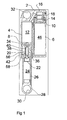
- Figure 1 is a sectional view of a suspension unit in a rebound condition;
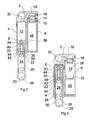
- Figure 2 corresponds to Figure 1 but shows the unit in a static condition, with some components shown in a simplified form; and
- Figure 3 corresponds to Figure 2, but shows the unit under jounce condition.
- As shown in Figure 1, the unit comprises a
support block 2 into which twocylindrical housings hand housing 4 as seen in Figure 1 constitutes a cylinder in which apiston 8 is slidable. The right-hand housing 6 constitutes a gas spring chamber, within which there is amovable partition 10. Theregion 12 of thecylinder 4 above thepiston 8 communicates with theregion 14 of the spring chamber above thepartition 10 throughpassageways 16 and adamping element 18. - The
piston 8 is secured to a connectingrod 20 having, at its end away from thepiston 8, asecondary piston 22. Thesecondary piston 22 is slidable in thehollow interior 24 of apiston rod 26. Thepiston rod 26 is closed at its lower end by asupport block 28 provided with ajournal 30. Asimilar journal 32 is provided in theupper support block 2. At its upper end, thepiston rod 26 has anend wall 56, through which the connectingrod 20 extends. - The downwards movement of the piston 8 (ie movement in the direction to increase the volume of the region 12) is limited by a
shoulder 34 in thecylinder 4, against which the piston abuts in the condition shown in Figure 1. Consequently, the interior of thecylinder 4 has alower region 36 having a smaller diameter than theregion 12 above thepiston 8. The connectingrod 26 is slidable within thislower region 36. In the condition shown in Figure 1, the upper end of the connectingrod 26 is spaced from thepiston 8 to define within the lower region 36 afirst damping chamber 38. Thedamping chamber 38 communicates with the interior of the connectingrod 20 throughapertures 40 situated close to thepiston 8.Further apertures 42 are provided in the connectingrod 20, near thesecondary piston 22. Theapertures first chamber 38 and a second chamber 44 (described below) via the interior of the connectingrod 20. - In the condition shown in Figure 1, the
region 12 of thecylinder 4 above thepiston 8, theregion 14 of the spring chamber in thehousing 6 above thepartition 10, thepassageways 16, thefirst damping chamber 38 and the interior of the connectingrod 20 are filled with oil or other hydraulic fluid. Theregion 46 of the spring chamber below thepartition 10 and theinterior 24 of thepiston rod 26 below thesecond piston 22 are filled with nitrogen or other suitable gas. Suitable means (not shown) is provided for supplying oil to thepassageways 16 and the other oil-filled regions. Oil from theregion 12 can pass to the first andsecond damping chambers rod 20 and theapertures regions - For operation, the suspension unit shown in the Figures is mounted to the body or other main structure of a vehicle by means of the
journal 32 and to a wheel or other unsprung components by means of thejournal 30. In a preferred embodiment, the vehicle is a track-laying vehicle, and thesupport block 28 is connected to a track guidance wheel over which runs a track of the vehicle. Thus, in practice, the vehicle will have more than one of the suspension units shown in the Figures, each supporting the vehicle structure on a respective track guidance wheel. - In the static condition of the vehicle, the suspension unit will assume the condition shown in Figure 2. In this condition, the pressure in the
lower region 46 of the spring chamber within thehousing 6 is sufficient to support the full load on the unit applied by the weight of the vehicle structure. Consequently, thepiston 8 is maintained in abutment with theshoulder 34. Theshoulder 34 thus establishes the ride height of the vehicle, regardless of the temperature, and therefore pressure, of the gas in theregion 46. By contrast, the pressure of the gas in thehollow interior 24 of the connectingrod 26 is not sufficient to support the load imposed by the weight of the vehicle, and so thepiston rod 26 is displaced upwardly in theregion 36 of thecylinder 4 to abut the underside of thepiston 8. The gas in theinterior 24 of thepiston rod 26 is thus compressed. In this condition, theend wall 56 of thepiston rod 26 is moved away from theupper face 58 of thesecond piston 22, to open up thesecond damping chamber 44. In the static condition shown in Figure 2, thepiston 8 and thepiston rod 26 abut each other to define a retracted end position. - During travel of the vehicle over rough terrain, upward loads are applied to the
piston rod 26 by the track guidance wheel supported at thejournal 32. These loads force thepiston rod 26 upwards, taking with it thepiston 8, producing the jounce condition shown in Figure 3. Oil is displaced from theregion 12 of thecylinder 4, through thepassageways 16 and thedamping element 18, into theupper region 14 of thespring chamber 6. Thepartition 10 is forced downwardly, so compressing the gas in theregion 46 of the spring chamber. When the load on the wheel is reduced, the pressure in thelower region 46 of the spring chamber returns the unit towards the static condition of Figure 2. The movement of the suspension unit is damped by thedamping element 18. - In the condition of rebound, as shown in Figure 1, where the load on the unit is reduced below the normal static load, the pressure in the
interior 24 of thepiston rod 26 causes thepiston rod 26 to move to an extended end position relative to thepiston 8. In this condition, as described above, theend wall 56 abuts theend face 58 of thesecondary piston 22 to define an extended end position of thepiston 8 and thepiston rod 26. Thepiston 8 is supported on theshoulder 34, so that Figure 1 shows the maximum extended condition of the unit. - In order to avoid heavy shock loads as the
end wall 56 contacts thepiston 8 and theend face 58 at the extended and retracted end positions, damping is provided by the first and second dampingchambers apertures second chamber 44, through theapertures 42 to the interior of the connectingrod 20. From there, the oil flows through theapertures 40 into the first dampingchamber 38. Theapertures end wall 56 along the connectingrod 20. As theend wall 56 approaches theend face 58 of thesecond piston 22, it moves over theapertures 42, progressively closing them. The reducing flow cross-section of theapertures 42 further restricts the flow of oil, so decelerating theend wall 56 before it strikes theend face 58. - A corresponding damping effect is achieved as the connecting
rod 26 and thepiston 8 move towards the retracted end position shown in Figure 2. As theend wall 56 moves upwardly, the reducing volume of the first dampingchamber 38 causes oil to be displaced into the connectingrod 20 through theapertures 40, and then through theapertures 42 into the second dampingchamber 44. As theend wall 56 approaches thepiston 8 it moves over theapertures 40, so decelerating thepiston rod 26 as before. - Although the
apertures rod 20, or have any suitable alternative shape selected to achieve a desired deceleration profile to ensure smooth operation of the unit.
Claims (16)
- A suspension unit comprising a cylinder (4) in which a piston (8) is slidable, the piston (8) being connected to a piston rod (26) for displacement relative to the piston rod (26) between extended and retracted end positions, and being resiliently biased towards one of the end positions, characterised in that damping means (38, 44, 40, 42) is provided for damping relative movement of the piston (8) and the piston rod (26) towards at least one of the end positions.
- A suspension unit as claimed in claim 1, characterised in that the piston (8) is resiliently biased towards the extended end position.
- A suspension unit as claimed in claim 1 or 2, characterised in that the damping means (38, 44, 40, 42) damps relative movement of the piston (8) and the piston rod (26) towards both end positions.
- A suspension unit as claimed in any one of the preceding claims, characterised in that the retracted end position is defined by contact between the piston (8) and the piston rod (26).
- A suspension unit as claimed in any one of the preceding claims, characterised in that the damping means comprises at least one damping chamber (38, 44) which varies in volume with relative movement between the piston (8) and the piston rod (26), and a restrictor (40, 42) controlling the flow rate of the fluid into or out of the damping chamber (38, 44).
- A suspension unit as claimed in claim 5, characterised in that a first damping chamber (38) is defined within the cylinder (4) between the piston (8) and the piston rod (26).
- A suspension unit as claimed in claim 6, characterised in that the piston rod (26) has a hollow interior (24), the piston (8) being connected to a secondary piston (22) disposed within the hollow interior (24).
- A suspension unit as claimed in claim 7, characterised in that the extended end position is defined by contact between an end wall (56) of the piston rod (26) and the secondary piston (22).
- A suspension unit as claimed in claim 8, characterised in that the secondary piston (22) and the end wall (56) define a second damping chamber (44).
- A suspension unit as claimed in claim 9, characterised in that the connecting rod (20) has a hollow interior, the restrictor comprising apertures (40, 42) in the connecting rod which permit fluid flow between the first and second damping chambers (38, 44) through the interior of the connecting rod (20).
- A suspension unit as claimed in claim 10, characterised in that the apertures (40, 42) comprise at least one aperture (40) disposed adjacent the piston (8), whereby the end wall (56) extends over the aperture (40) in the retracted end position.
- A suspension unit as claimed in claim 10 or 11, characterised in that the apertures (40, 42) comprise at least one aperture (42) disposed adjacent the secondary piston (22) whereby the end wall (56) extends over the aperture (42) in the extended end position.
- A suspension unit as claimed in any one of claims 7 to 12, characterised in that the piston (8) is biased relatively to the piston rod (26) towards the extended end position by gas pressure acting on the secondary piston (22).
- A suspension unit as claimed in any one of the preceding claims, characterised in that the unit includes a spring chamber (6) containing a movable partition (10), the interior (14) of the spring chamber (6) on one side of the partition (10) communicating with the interior (12) of the cylinder (4) on the side of the piston (8) away from the piston rod (26), the interior (12) of the cylinder (4) and the interior (14) of the spring chamber (6) on said one side of the partition (10) being oil-filled, and the interior (46) of the spring chamber (6) on the other side of the partition (10) containing gas under pressure.
- A vehicle having a suspension unit in accordance with any one of the preceding claims.
- A vehicle as claimed in claim 15, characterised in that the vehicle is a track-laying vehicle, the suspension unit being connected between the vehicle structure and a track guidance wheel.
Priority Applications (7)
| Application Number | Priority Date | Filing Date | Title |
|---|---|---|---|
| AT06254770T ATE423925T1 (en) | 2006-09-13 | 2006-09-13 | SUSPENSION DEVICE |
| EP06254770A EP1900963B1 (en) | 2006-09-13 | 2006-09-13 | A suspension unit |
| DE602006005365T DE602006005365D1 (en) | 2006-09-13 | 2006-09-13 | suspension device |
| CA2661544A CA2661544C (en) | 2006-09-13 | 2007-09-10 | A suspension unit |
| KR1020097004576A KR101404558B1 (en) | 2006-09-13 | 2007-09-10 | Suspension unit |
| US12/440,576 US8640835B2 (en) | 2006-09-13 | 2007-09-10 | Suspension unit |
| PCT/GB2007/003406 WO2008032031A1 (en) | 2006-09-13 | 2007-09-10 | A suspension unit |
Applications Claiming Priority (1)
| Application Number | Priority Date | Filing Date | Title |
|---|---|---|---|
| EP06254770A EP1900963B1 (en) | 2006-09-13 | 2006-09-13 | A suspension unit |
Publications (2)
| Publication Number | Publication Date |
|---|---|
| EP1900963A1 true EP1900963A1 (en) | 2008-03-19 |
| EP1900963B1 EP1900963B1 (en) | 2009-02-25 |
Family
ID=37709617
Family Applications (1)
| Application Number | Title | Priority Date | Filing Date |
|---|---|---|---|
| EP06254770A Active EP1900963B1 (en) | 2006-09-13 | 2006-09-13 | A suspension unit |
Country Status (7)
| Country | Link |
|---|---|
| US (1) | US8640835B2 (en) |
| EP (1) | EP1900963B1 (en) |
| KR (1) | KR101404558B1 (en) |
| AT (1) | ATE423925T1 (en) |
| CA (1) | CA2661544C (en) |
| DE (1) | DE602006005365D1 (en) |
| WO (1) | WO2008032031A1 (en) |
Cited By (3)
| Publication number | Priority date | Publication date | Assignee | Title |
|---|---|---|---|---|
| DE102008002062B3 (en) * | 2008-05-29 | 2009-11-26 | Zf Friedrichshafen Ag | Vibration damper with amplitude-dependent damping force |
| EP2390528A2 (en) | 2010-05-25 | 2011-11-30 | Horstman Defence Systems Limited | Suspension system |
| WO2011154107A1 (en) * | 2010-06-09 | 2011-12-15 | Rheinmetall Landsysteme Gmbh | Hydrop element |
Families Citing this family (18)
| Publication number | Priority date | Publication date | Assignee | Title |
|---|---|---|---|---|
| GB2480631B (en) * | 2010-05-25 | 2016-06-22 | Horstman Defence Systems Ltd | Suspension unit |
| US9232687B2 (en) | 2010-09-15 | 2016-01-12 | Dawn Equipment Company | Agricultural systems |
| US8544397B2 (en) | 2010-09-15 | 2013-10-01 | Dawn Equipment Company | Row unit for agricultural implement |
| US9271437B2 (en) | 2011-07-01 | 2016-03-01 | Charles H. Martin | Agricultural field preparation device |
| US10721855B2 (en) | 2014-02-05 | 2020-07-28 | Dawn Equipment Company | Agricultural system for field preparation |
| US10444774B2 (en) | 2014-11-07 | 2019-10-15 | Dawn Equipment Company | Agricultural system |
| US11197411B2 (en) | 2014-11-07 | 2021-12-14 | Dawn Equipment Company | Agricultural planting system with automatic depth control |
| US10582653B2 (en) | 2014-11-07 | 2020-03-10 | Dawn Equipment Company | Agricultural planting system with automatic depth control |
| US9681601B2 (en) * | 2015-01-09 | 2017-06-20 | Dawn Equipment Company | Hydraulic cylinder for an agricultural row unit having an uplift accumulator and a down pressure accumulator |
| US9723778B2 (en) * | 2014-11-07 | 2017-08-08 | Dawn Equipment Company | Agricultural system |
| US10980174B2 (en) | 2015-12-28 | 2021-04-20 | Underground Agriculture, LLC | Agricultural mowing device |
| US11083134B2 (en) | 2015-12-28 | 2021-08-10 | Underground Agriculture, LLC | Agricultural inter-row mowing device |
| US11006563B2 (en) | 2017-05-04 | 2021-05-18 | Dawn Equipment Company | Seed firming device for improving seed to soil contact in a planter furrow with feature designed to prevent the buildup of soil on the outer surfaces by discharging pressurized fluid |
| US10548260B2 (en) | 2017-05-04 | 2020-02-04 | Dawn Equipment Company | System for automatically setting the set point of a planter automatic down pressure control system with a seed furrow sidewall compaction measurement device |
| US10645865B2 (en) | 2017-05-04 | 2020-05-12 | Dawn Equipment Company | Agricultural row unit with automatic control system for furrow closing device |
| US11434968B2 (en) * | 2019-02-25 | 2022-09-06 | Mark Brendan Newhan | Vehicle shock absorber |
| EP3753763B1 (en) | 2019-06-20 | 2022-10-19 | The Dynamic Engineering Solution Pty Ltd | Vehicle suspension system |
| EP4100660A2 (en) | 2020-02-07 | 2022-12-14 | Timoney Dynamic Solutions Limited | Motor vehicle suspension gas spring |
Citations (5)
| Publication number | Priority date | Publication date | Assignee | Title |
|---|---|---|---|---|
| DE1995279U (en) * | 1968-07-15 | 1968-10-24 | Hans Prasse | HYDRAULIC TELESCOPIC VIBRATION DAMPER. |
| US20020112931A1 (en) * | 2001-01-12 | 2002-08-22 | Zfsachs Ag | Telescopic vibration damper |
| US20030127293A1 (en) * | 2000-01-15 | 2003-07-10 | Horst Rosenfeldt | Passive force element on the basis of electrorheologic liquids |
| ES2221533A1 (en) * | 2002-07-26 | 2004-12-16 | Manuel Carcare Gimeno | Variable suspension cylinder for vehicle, has two telescopic pistons provided such that one of telescopic pistons is operated when vehicle is idle, and two telescopic pistons are operated when vehicle is fully-loaded |
| EP1657470A1 (en) * | 2004-11-11 | 2006-05-17 | Krauss-Maffei Wegmann GmbH & Co. KG | Hydropneumatic spring for vehicle, especially tracked vehicle |
Family Cites Families (10)
| Publication number | Priority date | Publication date | Assignee | Title |
|---|---|---|---|---|
| US2563518A (en) * | 1951-08-07 | Tail wheel installation | ||
| US2363485A (en) | 1942-03-30 | 1944-11-28 | Automotive Prod Co Ltd | Telescopic shock absorber |
| US4815716A (en) * | 1985-08-26 | 1989-03-28 | Unisys Corporation | Telescoping strut shock isolator |
| JP3840550B2 (en) | 1999-04-20 | 2006-11-01 | カヤバ工業株式会社 | Vehicle suspension system |
| DE19918195C1 (en) * | 1999-04-22 | 2000-09-28 | Klaus Leben | Tension/compression buffer for rail vehicle or automobile coupling has piston element displaced from neutral position in opposite directions with hydraulic damping of its return movement |
| US6340153B1 (en) * | 2000-11-02 | 2002-01-22 | General Dynamics Advanced Technology Systems, Inc. | Shock and acoustic mount |
| JP3795792B2 (en) | 2001-11-05 | 2006-07-12 | 三菱電機株式会社 | Multistage hydraulic shock absorber |
| US20040188897A1 (en) * | 2003-03-26 | 2004-09-30 | Visteon Global Technologies, Inc. | Compressible fluid strut |
| JP4325417B2 (en) | 2003-04-10 | 2009-09-02 | 三菱電機株式会社 | Hydraulic shock absorber |
| US7441638B2 (en) * | 2004-12-09 | 2008-10-28 | Kayaba Industry Co., Ltd. | Front fork |
-
2006
- 2006-09-13 DE DE602006005365T patent/DE602006005365D1/en active Active
- 2006-09-13 EP EP06254770A patent/EP1900963B1/en active Active
- 2006-09-13 AT AT06254770T patent/ATE423925T1/en not_active IP Right Cessation
-
2007
- 2007-09-10 WO PCT/GB2007/003406 patent/WO2008032031A1/en active Application Filing
- 2007-09-10 KR KR1020097004576A patent/KR101404558B1/en active IP Right Grant
- 2007-09-10 US US12/440,576 patent/US8640835B2/en active Active
- 2007-09-10 CA CA2661544A patent/CA2661544C/en active Active
Patent Citations (5)
| Publication number | Priority date | Publication date | Assignee | Title |
|---|---|---|---|---|
| DE1995279U (en) * | 1968-07-15 | 1968-10-24 | Hans Prasse | HYDRAULIC TELESCOPIC VIBRATION DAMPER. |
| US20030127293A1 (en) * | 2000-01-15 | 2003-07-10 | Horst Rosenfeldt | Passive force element on the basis of electrorheologic liquids |
| US20020112931A1 (en) * | 2001-01-12 | 2002-08-22 | Zfsachs Ag | Telescopic vibration damper |
| ES2221533A1 (en) * | 2002-07-26 | 2004-12-16 | Manuel Carcare Gimeno | Variable suspension cylinder for vehicle, has two telescopic pistons provided such that one of telescopic pistons is operated when vehicle is idle, and two telescopic pistons are operated when vehicle is fully-loaded |
| EP1657470A1 (en) * | 2004-11-11 | 2006-05-17 | Krauss-Maffei Wegmann GmbH & Co. KG | Hydropneumatic spring for vehicle, especially tracked vehicle |
Cited By (5)
| Publication number | Priority date | Publication date | Assignee | Title |
|---|---|---|---|---|
| DE102008002062B3 (en) * | 2008-05-29 | 2009-11-26 | Zf Friedrichshafen Ag | Vibration damper with amplitude-dependent damping force |
| EP2390528A2 (en) | 2010-05-25 | 2011-11-30 | Horstman Defence Systems Limited | Suspension system |
| WO2011154107A1 (en) * | 2010-06-09 | 2011-12-15 | Rheinmetall Landsysteme Gmbh | Hydrop element |
| AT514781A5 (en) * | 2010-06-09 | 2015-03-15 | Rheinmetall Landsysteme Gmbh | Hydropneumatic element |
| AT514781B1 (en) * | 2010-06-09 | 2015-06-15 | Rheinmetall Landsysteme Gmbh | Hydropneumatic element |
Also Published As
| Publication number | Publication date |
|---|---|
| KR101404558B1 (en) | 2014-06-09 |
| KR20090063210A (en) | 2009-06-17 |
| ATE423925T1 (en) | 2009-03-15 |
| US8640835B2 (en) | 2014-02-04 |
| EP1900963B1 (en) | 2009-02-25 |
| DE602006005365D1 (en) | 2009-04-09 |
| CA2661544A1 (en) | 2008-03-20 |
| US20090260902A1 (en) | 2009-10-22 |
| WO2008032031A1 (en) | 2008-03-20 |
| CA2661544C (en) | 2015-06-02 |
Similar Documents
| Publication | Publication Date | Title |
|---|---|---|
| EP1900963B1 (en) | A suspension unit | |
| CN107878139B (en) | Vehicle leveling system | |
| US4159106A (en) | Vehicular suspension unit | |
| CN1871452A (en) | Stroke dependent bypass | |
| JP2010507047A (en) | Shock absorber with continuously adjustable semi-active valve | |
| KR101518097B1 (en) | Hydropneumatic suspension unit | |
| KR100766854B1 (en) | Shock absorber | |
| US6511085B2 (en) | Vehicle suspension apparatus | |
| CN106704442A (en) | Hydro-pneumatic spring | |
| US3799528A (en) | Vehicles self-pumping suspension strut | |
| CN101243266A (en) | Asymmetrical intake damper valve | |
| US4995597A (en) | Hydraulic shock absorber with telescopic casings | |
| EP1625956B1 (en) | Gas spring, arrangement and method for a gas spring | |
| KR100759931B1 (en) | Vehicular height control damper device | |
| KR101230549B1 (en) | Shock absorber | |
| EP2390529B1 (en) | Suspension unit | |
| JP4296015B2 (en) | Front fork | |
| EP0082710B1 (en) | Shock absorber and air spring assembly for tilt cab vehicle | |
| KR101662223B1 (en) | Shock absorber with a frequency unit | |
| CN113431862B (en) | Automobile cylinder type hydraulic shock absorber | |
| WO2018082958A1 (en) | Shock absorber and vehicle | |
| KR102610749B1 (en) | Vehicle shock absorber | |
| KR100245182B1 (en) | Shock absorber having variable oil orifice | |
| JPS6011255B2 (en) | Hydrodynamic suspension | |
| KR100722134B1 (en) | Vehicular height control damper device |
Legal Events
| Date | Code | Title | Description |
|---|---|---|---|
| PUAI | Public reference made under article 153(3) epc to a published international application that has entered the european phase |
Free format text: ORIGINAL CODE: 0009012 |
|
| AK | Designated contracting states |
Kind code of ref document: A1 Designated state(s): AT BE BG CH CY CZ DE DK EE ES FI FR GB GR HU IE IS IT LI LT LU LV MC NL PL PT RO SE SI SK TR |
|
| AX | Request for extension of the european patent |
Extension state: AL BA HR MK YU |
|
| 17P | Request for examination filed |
Effective date: 20080709 |
|
| GRAP | Despatch of communication of intention to grant a patent |
Free format text: ORIGINAL CODE: EPIDOSNIGR1 |
|
| AKX | Designation fees paid |
Designated state(s): AT BE BG CH CY CZ DE DK EE ES FI FR GB GR HU IE IS IT LI LT LU LV MC NL PL PT RO SE SI SK TR |
|
| GRAS | Grant fee paid |
Free format text: ORIGINAL CODE: EPIDOSNIGR3 |
|
| GRAA | (expected) grant |
Free format text: ORIGINAL CODE: 0009210 |
|
| AK | Designated contracting states |
Kind code of ref document: B1 Designated state(s): AT BE BG CH CY CZ DE DK EE ES FI FR GB GR HU IE IS IT LI LT LU LV MC NL PL PT RO SE SI SK TR |
|
| REG | Reference to a national code |
Ref country code: GB Ref legal event code: FG4D |
|
| REG | Reference to a national code |
Ref country code: CH Ref legal event code: EP Ref country code: CH Ref legal event code: NV Representative=s name: DR. LUSUARDI AG |
|
| REG | Reference to a national code |
Ref country code: IE Ref legal event code: FG4D |
|
| REF | Corresponds to: |
Ref document number: 602006005365 Country of ref document: DE Date of ref document: 20090409 Kind code of ref document: P |
|
| REG | Reference to a national code |
Ref country code: SE Ref legal event code: TRGR |
|
| PG25 | Lapsed in a contracting state [announced via postgrant information from national office to epo] |
Ref country code: LT Free format text: LAPSE BECAUSE OF FAILURE TO SUBMIT A TRANSLATION OF THE DESCRIPTION OR TO PAY THE FEE WITHIN THE PRESCRIBED TIME-LIMIT Effective date: 20090225 Ref country code: FI Free format text: LAPSE BECAUSE OF FAILURE TO SUBMIT A TRANSLATION OF THE DESCRIPTION OR TO PAY THE FEE WITHIN THE PRESCRIBED TIME-LIMIT Effective date: 20090225 Ref country code: SI Free format text: LAPSE BECAUSE OF FAILURE TO SUBMIT A TRANSLATION OF THE DESCRIPTION OR TO PAY THE FEE WITHIN THE PRESCRIBED TIME-LIMIT Effective date: 20090225 Ref country code: NL Free format text: LAPSE BECAUSE OF FAILURE TO SUBMIT A TRANSLATION OF THE DESCRIPTION OR TO PAY THE FEE WITHIN THE PRESCRIBED TIME-LIMIT Effective date: 20090225 |
|
| NLV1 | Nl: lapsed or annulled due to failure to fulfill the requirements of art. 29p and 29m of the patents act | ||
| PG25 | Lapsed in a contracting state [announced via postgrant information from national office to epo] |
Ref country code: PL Free format text: LAPSE BECAUSE OF FAILURE TO SUBMIT A TRANSLATION OF THE DESCRIPTION OR TO PAY THE FEE WITHIN THE PRESCRIBED TIME-LIMIT Effective date: 20090225 Ref country code: AT Free format text: LAPSE BECAUSE OF FAILURE TO SUBMIT A TRANSLATION OF THE DESCRIPTION OR TO PAY THE FEE WITHIN THE PRESCRIBED TIME-LIMIT Effective date: 20090225 Ref country code: IS Free format text: LAPSE BECAUSE OF FAILURE TO SUBMIT A TRANSLATION OF THE DESCRIPTION OR TO PAY THE FEE WITHIN THE PRESCRIBED TIME-LIMIT Effective date: 20090625 Ref country code: LV Free format text: LAPSE BECAUSE OF FAILURE TO SUBMIT A TRANSLATION OF THE DESCRIPTION OR TO PAY THE FEE WITHIN THE PRESCRIBED TIME-LIMIT Effective date: 20090225 |
|
| PG25 | Lapsed in a contracting state [announced via postgrant information from national office to epo] |
Ref country code: BE Free format text: LAPSE BECAUSE OF FAILURE TO SUBMIT A TRANSLATION OF THE DESCRIPTION OR TO PAY THE FEE WITHIN THE PRESCRIBED TIME-LIMIT Effective date: 20090225 |
|
| PG25 | Lapsed in a contracting state [announced via postgrant information from national office to epo] |
Ref country code: PT Free format text: LAPSE BECAUSE OF FAILURE TO SUBMIT A TRANSLATION OF THE DESCRIPTION OR TO PAY THE FEE WITHIN THE PRESCRIBED TIME-LIMIT Effective date: 20090812 Ref country code: DK Free format text: LAPSE BECAUSE OF FAILURE TO SUBMIT A TRANSLATION OF THE DESCRIPTION OR TO PAY THE FEE WITHIN THE PRESCRIBED TIME-LIMIT Effective date: 20090225 Ref country code: CZ Free format text: LAPSE BECAUSE OF FAILURE TO SUBMIT A TRANSLATION OF THE DESCRIPTION OR TO PAY THE FEE WITHIN THE PRESCRIBED TIME-LIMIT Effective date: 20090225 Ref country code: EE Free format text: LAPSE BECAUSE OF FAILURE TO SUBMIT A TRANSLATION OF THE DESCRIPTION OR TO PAY THE FEE WITHIN THE PRESCRIBED TIME-LIMIT Effective date: 20090225 Ref country code: ES Free format text: LAPSE BECAUSE OF FAILURE TO SUBMIT A TRANSLATION OF THE DESCRIPTION OR TO PAY THE FEE WITHIN THE PRESCRIBED TIME-LIMIT Effective date: 20090605 |
|
| PG25 | Lapsed in a contracting state [announced via postgrant information from national office to epo] |
Ref country code: RO Free format text: LAPSE BECAUSE OF FAILURE TO SUBMIT A TRANSLATION OF THE DESCRIPTION OR TO PAY THE FEE WITHIN THE PRESCRIBED TIME-LIMIT Effective date: 20090225 Ref country code: SK Free format text: LAPSE BECAUSE OF FAILURE TO SUBMIT A TRANSLATION OF THE DESCRIPTION OR TO PAY THE FEE WITHIN THE PRESCRIBED TIME-LIMIT Effective date: 20090225 |
|
| PLBE | No opposition filed within time limit |
Free format text: ORIGINAL CODE: 0009261 |
|
| STAA | Information on the status of an ep patent application or granted ep patent |
Free format text: STATUS: NO OPPOSITION FILED WITHIN TIME LIMIT |
|
| PG25 | Lapsed in a contracting state [announced via postgrant information from national office to epo] |
Ref country code: BG Free format text: LAPSE BECAUSE OF FAILURE TO SUBMIT A TRANSLATION OF THE DESCRIPTION OR TO PAY THE FEE WITHIN THE PRESCRIBED TIME-LIMIT Effective date: 20090525 |
|
| 26N | No opposition filed |
Effective date: 20091126 |
|
| PG25 | Lapsed in a contracting state [announced via postgrant information from national office to epo] |
Ref country code: MC Free format text: LAPSE BECAUSE OF NON-PAYMENT OF DUE FEES Effective date: 20090930 |
|
| REG | Reference to a national code |
Ref country code: IE Ref legal event code: MM4A |
|
| PG25 | Lapsed in a contracting state [announced via postgrant information from national office to epo] |
Ref country code: IE Free format text: LAPSE BECAUSE OF NON-PAYMENT OF DUE FEES Effective date: 20090913 |
|
| PG25 | Lapsed in a contracting state [announced via postgrant information from national office to epo] |
Ref country code: GR Free format text: LAPSE BECAUSE OF FAILURE TO SUBMIT A TRANSLATION OF THE DESCRIPTION OR TO PAY THE FEE WITHIN THE PRESCRIBED TIME-LIMIT Effective date: 20090526 |
|
| PG25 | Lapsed in a contracting state [announced via postgrant information from national office to epo] |
Ref country code: IT Free format text: LAPSE BECAUSE OF FAILURE TO SUBMIT A TRANSLATION OF THE DESCRIPTION OR TO PAY THE FEE WITHIN THE PRESCRIBED TIME-LIMIT Effective date: 20090225 |
|
| PG25 | Lapsed in a contracting state [announced via postgrant information from national office to epo] |
Ref country code: LU Free format text: LAPSE BECAUSE OF NON-PAYMENT OF DUE FEES Effective date: 20090913 |
|
| PG25 | Lapsed in a contracting state [announced via postgrant information from national office to epo] |
Ref country code: HU Free format text: LAPSE BECAUSE OF FAILURE TO SUBMIT A TRANSLATION OF THE DESCRIPTION OR TO PAY THE FEE WITHIN THE PRESCRIBED TIME-LIMIT Effective date: 20090826 |
|
| PG25 | Lapsed in a contracting state [announced via postgrant information from national office to epo] |
Ref country code: CY Free format text: LAPSE BECAUSE OF FAILURE TO SUBMIT A TRANSLATION OF THE DESCRIPTION OR TO PAY THE FEE WITHIN THE PRESCRIBED TIME-LIMIT Effective date: 20090225 |
|
| REG | Reference to a national code |
Ref country code: FR Ref legal event code: PLFP Year of fee payment: 11 |
|
| REG | Reference to a national code |
Ref country code: FR Ref legal event code: PLFP Year of fee payment: 12 |
|
| REG | Reference to a national code |
Ref country code: FR Ref legal event code: PLFP Year of fee payment: 13 |
|
| REG | Reference to a national code |
Ref country code: DE Ref legal event code: R082 Ref document number: 602006005365 Country of ref document: DE Representative=s name: HL KEMPNER PATENTANWAELTE, SOLICITORS (ENGLAND, DE Ref country code: DE Ref legal event code: R082 Ref document number: 602006005365 Country of ref document: DE Representative=s name: HL KEMPNER PATENTANWALT, RECHTSANWALT, SOLICIT, DE |
|
| PGFP | Annual fee paid to national office [announced via postgrant information from national office to epo] |
Ref country code: TR Payment date: 20230824 Year of fee payment: 18 |
|
| PGFP | Annual fee paid to national office [announced via postgrant information from national office to epo] |
Ref country code: SE Payment date: 20230918 Year of fee payment: 18 |
|
| PGFP | Annual fee paid to national office [announced via postgrant information from national office to epo] |
Ref country code: CH Payment date: 20231001 Year of fee payment: 18 |
|
| PGFP | Annual fee paid to national office [announced via postgrant information from national office to epo] |
Ref country code: DE Payment date: 20240924 Year of fee payment: 19 |
|
| PGFP | Annual fee paid to national office [announced via postgrant information from national office to epo] |
Ref country code: GB Payment date: 20240925 Year of fee payment: 19 |
|
| PGFP | Annual fee paid to national office [announced via postgrant information from national office to epo] |
Ref country code: FR Payment date: 20240909 Year of fee payment: 19 |