EP1900957A2 - Anordnung zur Betätigung einer Kupplung - Google Patents
Anordnung zur Betätigung einer Kupplung Download PDFInfo
- Publication number
- EP1900957A2 EP1900957A2 EP07016248A EP07016248A EP1900957A2 EP 1900957 A2 EP1900957 A2 EP 1900957A2 EP 07016248 A EP07016248 A EP 07016248A EP 07016248 A EP07016248 A EP 07016248A EP 1900957 A2 EP1900957 A2 EP 1900957A2
- Authority
- EP
- European Patent Office
- Prior art keywords
- arrangement according
- clutch
- guide tube
- actuating
- base plate
- Prior art date
- Legal status (The legal status is an assumption and is not a legal conclusion. Google has not performed a legal analysis and makes no representation as to the accuracy of the status listed.)
- Granted
Links
- 230000005540 biological transmission Effects 0.000 claims abstract description 15
- 238000006073 displacement reaction Methods 0.000 claims abstract description 10
- 230000008878 coupling Effects 0.000 claims description 4
- 238000010168 coupling process Methods 0.000 claims description 4
- 238000005859 coupling reaction Methods 0.000 claims description 4
- 238000010586 diagram Methods 0.000 description 8
- 230000003068 static effect Effects 0.000 description 3
- 230000006835 compression Effects 0.000 description 2
- 238000007906 compression Methods 0.000 description 2
- 230000000694 effects Effects 0.000 description 2
- 238000002485 combustion reaction Methods 0.000 description 1
- 238000011217 control strategy Methods 0.000 description 1
- 230000007423 decrease Effects 0.000 description 1
- 210000003746 feather Anatomy 0.000 description 1
- 238000005461 lubrication Methods 0.000 description 1
Images
Classifications
-
- F—MECHANICAL ENGINEERING; LIGHTING; HEATING; WEAPONS; BLASTING
- F16—ENGINEERING ELEMENTS AND UNITS; GENERAL MEASURES FOR PRODUCING AND MAINTAINING EFFECTIVE FUNCTIONING OF MACHINES OR INSTALLATIONS; THERMAL INSULATION IN GENERAL
- F16D—COUPLINGS FOR TRANSMITTING ROTATION; CLUTCHES; BRAKES
- F16D23/00—Details of mechanically-actuated clutches not specific for one distinct type
- F16D23/12—Mechanical clutch-actuating mechanisms arranged outside the clutch as such
- F16D23/14—Clutch-actuating sleeves or bearings; Actuating members directly connected to clutch-actuating sleeves or bearings
- F16D23/148—Guide-sleeve receiving the clutch release bearing
-
- F—MECHANICAL ENGINEERING; LIGHTING; HEATING; WEAPONS; BLASTING
- F16—ENGINEERING ELEMENTS AND UNITS; GENERAL MEASURES FOR PRODUCING AND MAINTAINING EFFECTIVE FUNCTIONING OF MACHINES OR INSTALLATIONS; THERMAL INSULATION IN GENERAL
- F16D—COUPLINGS FOR TRANSMITTING ROTATION; CLUTCHES; BRAKES
- F16D23/00—Details of mechanically-actuated clutches not specific for one distinct type
- F16D23/12—Mechanical clutch-actuating mechanisms arranged outside the clutch as such
-
- F—MECHANICAL ENGINEERING; LIGHTING; HEATING; WEAPONS; BLASTING
- F16—ENGINEERING ELEMENTS AND UNITS; GENERAL MEASURES FOR PRODUCING AND MAINTAINING EFFECTIVE FUNCTIONING OF MACHINES OR INSTALLATIONS; THERMAL INSULATION IN GENERAL
- F16D—COUPLINGS FOR TRANSMITTING ROTATION; CLUTCHES; BRAKES
- F16D21/00—Systems comprising a plurality of actuated clutches
- F16D21/02—Systems comprising a plurality of actuated clutches for interconnecting three or more shafts or other transmission members in different ways
- F16D21/06—Systems comprising a plurality of actuated clutches for interconnecting three or more shafts or other transmission members in different ways at least two driving shafts or two driven shafts being concentric
-
- F—MECHANICAL ENGINEERING; LIGHTING; HEATING; WEAPONS; BLASTING
- F16—ENGINEERING ELEMENTS AND UNITS; GENERAL MEASURES FOR PRODUCING AND MAINTAINING EFFECTIVE FUNCTIONING OF MACHINES OR INSTALLATIONS; THERMAL INSULATION IN GENERAL
- F16D—COUPLINGS FOR TRANSMITTING ROTATION; CLUTCHES; BRAKES
- F16D23/00—Details of mechanically-actuated clutches not specific for one distinct type
Definitions
- the present invention relates to an arrangement for actuating a clutch.
- An arrangement for actuating a clutch is for example from the DE 10313435 known. Due to friction always creates a dead zone in a rigid engagement system, ie when changing the direction of Aktorweges results in the clutch no change in the clutch travel and thus no torque change of the clutch. Even knowing the deadband, no robust control strategy can be developed that compensates for this behavior.
- An object of the present invention is therefore to provide an arrangement for actuating a clutch, which has a lower or as possible no dead zone.
- an arrangement for actuating a clutch in particular a clutch in the drive train of a motor vehicle, comprising a transmission means that is slidably mounted relative to a bearing in an actuating device, wherein the bearing is mounted resiliently in the actuating direction relative to a housing. It is therefore provided on the housing side of one or more friction points to arrange an additional elasticity, so that the friction points are no longer rigidly arranged against a housing-fixed mounting, but elastically with respect to the housing.
- the arrangement preferably comprises means for displacing the transmission means, in particular an actuator lever, and a means which is displaced by the transmission means, preferably this is a lever spring, which is in operative connection with the coupling.
- the transfer means is in a preferred embodiment, an engagement piston.
- the storage for the transfer means is in a preferred embodiment, a guide tube. It is preferably provided that the guide tube is connected with connecting means in the actuating direction elastically with a housing-fixed base plate.
- the connecting means preferably comprise springs, which are connected in the tensile and / or pressure direction resiliently connected to the guide tube and the base plate. By the springs, the guide tube can be moved elastically relative to the base plate.
- the connecting means preferably comprise bolts which limit the relative displacement between the guide tube and the base plate, wherein the bolts are preferably bolts which simultaneously form an axial guide and the stop.
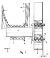
- Fig. 1 shows a sketch of a release system for a vehicle clutch in section. It is a so-called lever release, as he, for example, from the DE 10313435 known per se. An associated clutch, not shown here, for example, from the DE 103165445 known.
- Fig. 1 sketchy shown in section is a lever spring 1 for actuating the clutch not shown in the drive train of a motor vehicle between the internal combustion engine and reduction gear.
- the lever spring 1 is in the direction of the actuating travel Y by means of a Eingurkolbens 2, which is arranged displaceably in the direction of the actuating travel Y on a guide tube 3, actuated.
- the engagement piston 2 has on its side facing away from the lever spring 1 a disk 4, against which presses an actuator lever 5 for actuating the clutch, not shown.
- the actuator lever 5 moves during its actuation the engagement piston 2 and thus also the lever spring 1 for actuating the clutch, not shown here.
- Upon actuation of the engagement piston 2 slides on the guide tube 3.
- this sliding friction occurs, which has a proportion of so-called dry friction regardless of any lubrication and possibly a particularly smooth designed surface of the friction partners.
- dry friction as is known from physics, static friction must first be overcome, which requires a so-called breaking-open force in order to trigger a sliding movement.
- the guide tube 3 is no longer rigidly connected to a base plate 6, but the guide tube 3 is arranged to be resiliently displaceable in the direction of the actuating travel Y by a limited displacement path YF on the base plate 6.
- the guide tube on a mounting flange 7 which is rigidly connected to the guide tube 3, wherein the mounting flange 7 is resiliently connected to the base plate 6, which is fixed to the housing against a clutch bell or a transmission housing and thus rigidly connected.
- the spring-elastic connection between the guide tube 3 and the mounting flange 7 and the base plate 6 is displaceable by a distance YF in the direction of the actuating travel Y against a spring force.
- the resilient connection can for example be designed so that guide pins 8 are inserted into through holes through the mounting flange 7 and the base plate 6 and are provided with discs 9, so that here a displacement over the path YF is possible.
- the guide pins 8 and the discs 9 can be screwed together by means of nuts.
- the through holes additionally have non-continuous, ie blind hole introduced stepped holes in which springs 10 are arranged.
- the springs are secured to the base plate 6 as well as to the mounting flange 7, for example screwed or clamped, thus acting as tension and compression springs in the direction of the actuating travel Y.
- the springs may also be e.g. be designed only as compression springs and thereby be arranged alternately so that they are compressed in the direction Y zw. against the direction Y.
- the guide tube 3 has a play against spring force both in the direction Y and in the opposite direction.
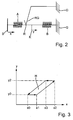
- Fig. 2 shows a mechanical equivalent circuit diagram of a lever system according to the prior art, ie without sliding guide tube 3 as in the embodiment of Fig. 1.
- the elasticities of the transmission link actuator lever 5 - engaging piston 2 - spring 1 are schematically divided into two springs, a spring A, which includes all the elasticities of the actuator lever and the actuator for its operation as an electric drive, transmission elements and the like, and a spring B, which comprises all the elasticities of the lever spring 1 and other elasticities of the coupling, not shown.
- the slidable mounting of the engagement piston 2 on the guide tube 3 is shown as a friction point R with dry friction, wherein the friction point R comprises a housing-mounted friction element RG.
- Housing fixed bearings are each denoted by G.
- the Side S corresponds to the actuator travel of an actuator shown only schematically by the actuator X for actuating the actuator lever 5, a direction indicated by a vertical line point K corresponds to the clutch Y in Fig. 1.
- a movement of the actuator (actuator) S by a distance X. (Aktorweg, whilrweg) is first to overcome the dry friction at the point R against the elasticity of the spring A until a movement of the engaging piston 2 and - minus the interposed elasticity - the coupling takes place by a distance Y. This effect ensures that a hysteresis according to FIG. 3 occurs.
- Value pairs X / Y are designated in FIG. 3 and 5 each with the same index. In Fig.
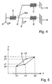
- Such a lever system is shown as a mechanical equivalent circuit diagram in Fig. 4.
- a possible embodiment for the arrangement of this elasticity is the exemplary embodiment according to FIG. 1.
- the elasticity C is, like the elasticities A and B, a spring-elastic element.
- the elasticity C is effected in the embodiment of FIG. 1 by the elastic displacement of the guide tube 3 relative to the base plate 6, ie by the parallel connection of the springs 10.
- the possible displacement between two YF is designed so that the spring force of the springs 10 at a maximum Displacement of the guide tube 3 relative to the base plate 6, ie a full utilization of the path YF, would be greater than the static frictional force between engagement piston 2 and guide tube 3.
- the Stiction between guide tube 3 and engaging piston 2 overcome.
- Fig. 5 shows a diagram of the travel X over the clutch path Y corresponding to Fig. 3.
- the area enclosed by the hysteresis curve is smaller than in the prior art system.
- the parts of the curve running parallel to the abscissa in the prior art run in Fig. 3 from X0, Y0 to X1, Y0 and from X2, Y2 to X3, Y2, now with a determined by the elasticity of the spring C slope of X0 ', Y0'to X1', Y1 'and from X2', Y2'to X3 ', Y3'.
- Aktorweges X is now so at each point of the hysteresis curve a change in the clutch travel Y, there are no areas of the hysteresis curve with zero slope.
Landscapes
- Engineering & Computer Science (AREA)
- General Engineering & Computer Science (AREA)
- Mechanical Engineering (AREA)
- Mechanical Operated Clutches (AREA)
- Hydraulic Clutches, Magnetic Clutches, Fluid Clutches, And Fluid Joints (AREA)
Abstract
Description
- Die vorliegende Erfindung betrifft eine Anordnung zur Betätigung einer Kupplung.
- Eine Anordnung zur Betätigung einer Kupplung ist beispielsweise aus der
DE 10313435 bekannt. Aufgrund von Reibungen entsteht bei einem starren Einrücksystem immer eine Totzone, d.h. bei Richtungsänderung des Aktorweges ergibt sich an der Kupplung keine Änderung des Kupplungsweges und damit keine Momentenänderung der Kupplung. Auch bei Kenntnis der Totzone kann keine robuste Regelungsstrategie entwickelt werden, die dieses Verhalten kompensiert. - Eine Aufgabe der vorliegenden Erfindung ist es daher, eine Anordnung zur Betätigung einer Kupplung anzugeben, welche eine geringere oder möglichst keine Totzone aufweist.
- Dieses Problem wird gelöst durch eine Anordnung zur Betätigung einer Kupplung, insbesondere einer Kupplung im Antriebsstrang eines Kraftfahrzeuges, umfassend ein Übertragungsmittel, dass gegenüber einer Lagerung in einer Betätigungseinrichtung verschiebbar gelagert ist, wobei die Lagerung in Betätigungsrichtung federelastisch gegenüber einem Gehäuse gelagert ist. Es ist also vorgesehen, gehäuseseitig einer oder mehrerer Reibstellen eine zusätzliche Elastizität anzuordnen, so dass die Reibstellen nicht mehr starr gegen eine gehäusefeste Lagerung, sondern elastisch gegenüber dem Gehäuse angeordnet sind. Die Anordnung umfasst vorzugsweise Mittel zur Verschiebung des Übertragungsmittels, insbesondere einen Aktorhebel, sowie ein Mittel, das von dem Übertragungsmittel verschoben wird, vorzugsweise ist dies eine Hebelfeder, die in Wirkverbindung mit der Kupplung steht. Das Übertragungsmittel ist in einer bevorzugten Ausführungsform ein Einrückkolben. Die Lagerung für das Übertragungsmittel ist in einer bevorzugten Ausführungsform ein Führungsrohr. Vorzugsweise ist vorgesehen, dass das Führungsrohr mit Verbindungsmitteln in Betätigungsrichtung elastisch mit einer gehäusefesten Grundplatte verbunden ist. Die Verbindungsmittel umfassen vorzugsweise Federn, die in Zug- und/oder Druckrichtung belastbar mit dem Führungsrohr sowie der Grundplatte verbunden sind. Durch die Federn kann das Führungsrohr elastisch gegenüber der Grundplatte verschoben werden. Die Verbindungsmittel umfassen vorzugsweise Bolzen, die die Relativverschiebung zwischen Führungsrohr und Grundplatte begrenzen, wobei die Bolzen vorzugsweise Schraubenbolzen sind, die gleichzeitig eine axiale Führung sowie den Anschlag bilden.
- Im Folgenden wird ein Ausführungsbeispiel der Erfindung anhand der beiliegenden Zeichnungen erläutert. Dabei zeigen:
- Fig. 1
- eine schematische Darstellung eines Hebelsystems;
- Fig. 2
- ein mechanisches Ersatzschaltbild eines Hebelsystems nach Stand der Technik;
- Fig. 3
- eine Hysteresekurve zu dem mechanischen Ersatzschaltbild nach Fig. 2;
- Fig. 4
- ein mechanisches Ersatzschaltbild eines erfindungsgemäßen Hebelsystems;
- Fig. 5
- eine Hysteresekurve zu dem mechanischen Ersatzschaltbild nach Fig. 4.
- Fig. 1 zeigt eine Skizze eines Ausrücksystems für eine Fahrzeugkupplung im Schnitt. Es handelt sich hierbei um einen so genannten Hebelausrücker, wie er beispielsweise aus der
DE 10313435 an sich bekannt ist. Eine hier nicht dargestellte zugehörige Kupplung ist beispielsweise aus derDE 103165445 bekannt. In Fig. 1 skizzenhaft im Schnitt dargestellt ist eine Hebelfeder 1 zur Betätigung der nicht näher dargestellten Kupplung im Antriebsstrang eines Kraftfahrzeuges zwischen Verbrennungskraftmaschine und Untersetzungsgetriebe. Die Hebelfeder 1 wird in Richtung des Betätigungsweges Y mittels eines Einrückkolbens 2, der verschiebbar in Richtung des Betätigungsweges Y auf einem Führungsrohr 3 angeordnet ist, betätigt. - Der Einrückkolben 2 weist an seiner der Hebelfeder 1 abgewandten Seite eine Scheibe 4 auf, gegen die ein Aktorhebel 5 zur Betätigung der nicht dargestellten Kupplung drückt. Der Aktorhebel 5 verschiebt bei dessen Betätigung den Einrückkolben 2 und damit auch die Hebelfeder 1 zur Betätigung der hier nicht dargestellten Kupplung. Bei der Betätigung gleitet der Einrückkolben 2 auf dem Führungsrohr 3. Bei dieser Gleitbewegung tritt Reibung auf, welche unabhängig von einer eventuellen Schmierung und einer eventuell besonders glatt ausgestalteten Oberfläche der Reibpartner einen Anteil an so genannter trockener Reibung aufweist. Bei trockener Reibung ist zunächst, wie aus der Physik bekannt ist, eine Haftreibung zu überwinden, was eine so genannten Losreißkraft erfordert, um eine Gleitbewegung auszulösen.
- Die danach einsetzende Gleitreibung ist geringer als die Haftreibung. Dies hat zur Folge, dass für eine Relativbewegung des Einrückkolbens 2 gegenüber dem Führungsrohr 3 zunächst die Losreißkraft aufzubringen ist.
- Erfindungsgemäß ist nun vorgesehen, das Führungsrohr 3 nicht mehr starr mit einer Grundplatte 6 zu verbinden, sondern das Führungsrohr 3 federelastisch in Richtung des Betätigungsweges Y verschiebbar um einen begrenzten Verschiebeweg YF an der Grundplatte 6 anzuordnen. Dazu weist das Führungsrohr einen Befestigungsflansch 7 auf, der starr mit dem Führungsrohr 3 verbunden ist, wobei der Befestigungsflansch 7 federelastisch mit der Grundplatte 6, die gehäusefest gegenüber einer Kupplungsglocke oder einem Getriebegehäuse und damit starr befestigt ist, verbunden ist. Die federelastische Verbindung zwischen dem Führungsrohr 3 bzw. dem Befestigungsflansch 7 und der Grundplatte 6 ist um einen Weg YF in Richtung des Betätigungsweges Y gegen eine Federkraft verschiebbar. Die federelastische Verbindung kann beispielsweise so ausgelegt sein, dass Führungsbolzen 8 in Durchgangsbohrungen durch den Befestigungsflansch 7 und die Grundplatte 6 gesteckt sind und mit Scheiben 9 versehen sind, so dass hier ein Verschiebeweg um den Weg YF möglich ist. Die Führungsbolzen 8 und die Scheiben 9 können mittels Muttern miteinander verschraubt sein. Die Durchgangsbohrungen weisen zusätzlich nicht durchgehende, also sacklochartig eingebrachte Stufenbohrungen auf, in denen Federn 10 angeordnet sind. Die Federn sind beispielsweise an der Grundplatte 6 sowie an dem Befestigungsflansch 7 befestigt, beispielsweise verschraubt oder geklemmt, und wirken so als Zug- und Druckfedern in Richtung des Betätigungsweges Y. Alternativ können die Federn auch z.B. nur als Druckfedern ausgebildet sein und dabei abwechselnd so angeordnet sein, dass diese in Richtung Y zw. Entgegen der Richtung Y zusammengedrückt werden. In allen Fällen weist das Führungsrohr 3 ein Spiel gegen Federkraft sowohl in Richtung Y als auch in die Gegenrichtung auf.
- Fig. 2 zeigt ein mechanisches Ersatzschaltbild eines Hebelsystems nach Stand der Technik, also ohne verschiebbares Führungsrohr 3 wie im Ausführungsbeispiel der Fig. 1. Bei dem Ersatzschaltbild der Fig. 2 sind die Elastizitäten der Übertragungsstrecke Aktorhebel 5 - Einrückkolben 2 -Hebelfeder 1 schematisch aufgeteilt in zwei Federn, eine Feder A, die sämtliche Elastizitäten des Aktorhebels und des Aktors zu dessen Betätigung wie einem elektrischen Antrieb, Getriebeelementen und dergleichen umfasst, sowie eine Feder B, die sämtliche Elastizitäten der Hebelfeder 1 und weiterer Elastizitäten der nicht dargestellten Kupplung umfasst. Die verschiebbare Lagerung des Einrückkolbens 2 auf dem Führungsrohr 3 ist als Reibungsstelle R mit trockener Reibung dargestellt, wobei die Reibungsstelle R ein gehäusefestes Reibelement RG umfasst. Gehäusefeste Lagerungen sind jeweils mit G bezeichnet. Die Seite S entspricht dem Stellerweg eines nur schematisch anhand des Stellerweges X dargestellten Aktors zur Betätigung des Aktorhebels 5, ein durch einen senkrechten Strich angedeuteter Punkt K entspricht dem Kupplungsweg Y in Fig. 1. Bei einer Bewegung des Aktors (Stellers) S um einen Weg X (Aktorweg, Stellerweg) ist zunächst die trockene Reibung an der Stelle R gegen die Elastizität der Feder A zu überwinden, bis eine Bewegung des Einrückkolbens 2 und - abzüglich der dazwischen angeordneten Elastizität - der Kupplung um einen Weg Y stattfindet. Dieser Effekt sorgt dafür, dass eine Hysterese gemäß Fig. 3 auftritt. Wertepaare X/Y sind in Fig. 3 und 5 jeweils mit gleichem Index bezeichnet. In Fig. 3 ist auf der Abszisse der Weg X des Stellers und auf der Ordinate der Kupplungsweg Y aufgetragen. Durch die trockene Reibung ist, ausgehend von einem Stellerweg X = X0 bis X = X1 kein Weg Y in der Kupplung zu beobachten, der Kupplungsweg bleibt bei einem Wert Y0. Erst ausgehend von einem Weg X1, bewirkt eine Erhöhung des Stellerwegs X eine Auswirkung auf den Kupplungsweg Y. Gleiches gilt bei Erreichen eines Wertes X2 des Stellers und einer Umkehr der Bewegungsrichtung, hier bleibt zunächst der Kupplungsweg Y konstant und verringert sich erst nach Zurücklegen eines bestimmten Stellerweges. Um diese zu verringern wird nun erfindungsgemäß vorgeschlagen, in den Reibungszweig RG gemäß Fig. 2 eine weitere Elastizität C anzuordnen. Ein derartiges Hebelsystem ist als mechanisches Ersatzschaltbild in Fig. 4 dargestellt. Eine mögliche Ausführungsform zur Anordnung dieser Elastizität ist das Ausführungsbeispiel gemäß Fig. 1. Bei der Elastizität C handelt es sich wie bei den Elastizitäten A und B um ein federelastisches Element. Die Elastizität C wird im Ausführungsbeispiel der Fig. 1 durch die federelastische Verschiebbarkeit des Führungsrohres 3 gegenüber der Grundplatte 6 bewirkt, also durch die Parallelschaltung der Federn 10. Der zwischen beiden mögliche Verschiebeweg YF ist so ausgelegt, dass die Federkraft der Federn 10 bei einer maximalen Verschiebung des Führungsrohres 3 gegenüber der Grundplatte 6, also einem vollen Ausnutzen des Weges YF, größer würde als die Haftreibungskraft zwischen Einrückkolben 2 und Führungsrohr 3. Vor einem Anschlag des Führungsrohres 3 an die Grundplatte 6, bevor also der maximale Verschiebeweg ausgenutzt ist, wird die Haftreibung zwischen Führungsrohr 3 und Einrückkolben 2 überwunden.
- Fig. 5 zeigt ein Diagramm des Stellweg X über dem Kupplungsweg Y entsprechend der Fig. 3. Bei der erfindungsgemäßen Anordnung ist die von der Hysteresekurve eingeschlossene Fläche kleiner als bei dem System nach Stand der Technik. Zudem verlaufen die im Stand der Technik parallel zur Abszisse verlaufenden Teile der Kurve, in Fig. 3 von X0, Y0 nach X1, Y0 und von X2, Y2 nach X3, Y2, nunmehr mit einer durch die Elastizität der Feder C bestimmten Steigung von X0', Y0'nach X1', Y1' und von X2', Y2'nach X3', Y3'. Bei einer Veränderung des Aktorweges X erfolgt nun also an jedem Punkt der Hysteresekurve eine Veränderung des Kupplungsweges Y, es gibt keine Bereiche der Hysteresekurve mit Steigung null.
-
- 1
- Hebelfeder
- 2
- Einrückkolben
- 3
- Führungsrohr
- 4
- Scheibe
- 5
- Aktorhebel
- 6
- Grundplatte
- 7
- Befestigungsflansch
- 8
- Schraube
- 9
- Mutter
- 10
- Feder
- X
- Stellweg des Aktors
- Y
- Betätigungsweges der Kupplung
- YF
- Verschiebeweg
Claims (10)
- Anordnung zur Betätigung einer Kupplung, insbesondere einer Kupplung im Antriebsstrang eines Kraftfahrzeuges, umfassend ein Übertragungsmittel (2), das gegenüber einer Lagerung (3) in einer Betätigungsrichtung verschiebbar gelagert ist, dadurch gekennzeichnet, dass die Lagerung in Betätigungsrichtung federelastisch gegenüber einem Gehäuse (6) gelagert ist.
- Anordnung nach Anspruch 1, dadurch gekennzeichnet, dass diese ein Mittel zur Verschiebung des Übertragungsmittels (2) sowie ein Mittel, das von dem Übertragungsmittels (2) verschoben wird, umfasst.
- Anordnung nach Anspruch 1 oder 2, dadurch gekennzeichnet, dass das Mittel zur Verschiebung des Übertragungsmittels (2) ein Aktorhebel (5) ist.
- Anordnung nach einem der Ansprüche 1 bis 3, dadurch gekennzeichnet, dass das Mittel, das von dem Übertragungsmittels (2) verschoben wird, eine Hebelfeder (1) ist, die in Wirkverbindung mit der Kupplung steht.
- Anordnung nach einem der Ansprüche 1 bis 4, dadurch gekennzeichnet, dass das Übertragungsmittel (2) ein Einrückkolben (2) ist.
- Anordnung nach einem der Ansprüche 1 bis 5, dadurch gekennzeichnet, dass die Lagerung (3) ein Führungsrohr (3) ist.
- Anordnung nach Anspruch 6, dadurch gekennzeichnet, dass das Führungsrohr (3) mit Verbindungsmitteln (8, 9, 10) in Betätigungsrichtung elastisch mit einer gehäusefesten Grundplatte (6) verbunden ist.
- Anordnung nach Anspruch 7, dadurch gekennzeichnet, dass die Verbindungsmittel Federn (10) umfassen, die in Zug- und/oder Druckrichtung belastbar mit dem Führungsrohr (3) sowie der Grundplatte (6) verbunden sind.
- Anordnung nach Anspruch 8, dadurch gekennzeichnet, dass die Verbindungsmittel Bolzen (8) umfassen, die die Relativverschiebung zwischen Führungsrohr (3) und Grundplatte (6) begrenzen.
- Anordnung nach Anspruch 8 oder 9, dadurch gekennzeichnet, dass die Bolzen (8) Schraubenbolzen sind, die gleichzeitig eine axiale Führung bilden.
Applications Claiming Priority (1)
| Application Number | Priority Date | Filing Date | Title |
|---|---|---|---|
| DE102006043620 | 2006-09-16 |
Publications (3)
| Publication Number | Publication Date |
|---|---|
| EP1900957A2 true EP1900957A2 (de) | 2008-03-19 |
| EP1900957A3 EP1900957A3 (de) | 2010-06-23 |
| EP1900957B1 EP1900957B1 (de) | 2011-07-06 |
Family
ID=38776134
Family Applications (1)
| Application Number | Title | Priority Date | Filing Date |
|---|---|---|---|
| EP07016248A Not-in-force EP1900957B1 (de) | 2006-09-16 | 2007-08-20 | Anordnung zur Betätigung einer Kupplung |
Country Status (5)
| Country | Link |
|---|---|
| US (1) | US8151966B2 (de) |
| EP (1) | EP1900957B1 (de) |
| KR (1) | KR101415355B1 (de) |
| AT (1) | ATE515646T1 (de) |
| DE (1) | DE102007039305A1 (de) |
Family Cites Families (10)
| Publication number | Priority date | Publication date | Assignee | Title |
|---|---|---|---|---|
| FR2317553A1 (fr) * | 1975-07-10 | 1977-02-04 | Skf Ind Trading & Dev | Embrayage, notamment pour vehicules automobiles |
| US4534458A (en) * | 1982-01-25 | 1985-08-13 | Federal-Mogul Corporation | Self-aligning clutch release bearing assembly |
| JP2839711B2 (ja) * | 1992-05-07 | 1998-12-16 | キュスター ウント コンパニー ゲゼルシャフト ミット ベシュレンクテル ハフツング | 機械的なフレキシブルな遠隔操作手段の長さ修正装置 |
| DE19535712C1 (de) * | 1995-09-26 | 1996-10-31 | Fichtel & Sachs Ag | Reibungskupplung im Antriebsstrang eines Kraftfahrzeuges |
| DE19736557C5 (de) * | 1997-08-22 | 2004-05-06 | Daimlerchrysler Ag | Reibungskupplung, insbesondere für Kraftfahrzeuge |
| US7370741B2 (en) * | 2002-01-21 | 2008-05-13 | Nsk Ltd. | Engine start roller clutch-housed type rotation transmission device |
| BR0303660A (pt) * | 2002-03-27 | 2004-07-13 | Luk Lamellen & Kupplungsbau | Sistema de desengate de embreagem para uma caixa de câmbio de embreagem dupla de um veìculo |
| WO2003087608A2 (de) * | 2002-04-10 | 2003-10-23 | Luk Lamellen Und Kupplungsbau Beteiligungs Kg | Kupplungsaggregat |
| DE10329194A1 (de) * | 2003-06-28 | 2005-01-20 | Zf Sachs Ag | Drehmomentübertragungssystem für einen Fahrzeugantriebsstrang |
| US7628094B2 (en) * | 2004-12-04 | 2009-12-08 | Mon Spencer Owyang | Cable tension adjustment assembly |
-
2007
- 2007-08-20 AT AT07016248T patent/ATE515646T1/de active
- 2007-08-20 DE DE102007039305A patent/DE102007039305A1/de not_active Withdrawn
- 2007-08-20 EP EP07016248A patent/EP1900957B1/de not_active Not-in-force
- 2007-09-13 US US11/901,116 patent/US8151966B2/en not_active Expired - Fee Related
- 2007-09-14 KR KR1020070093392A patent/KR101415355B1/ko not_active Expired - Fee Related
Non-Patent Citations (1)
| Title |
|---|
| None |
Also Published As
| Publication number | Publication date |
|---|---|
| EP1900957A3 (de) | 2010-06-23 |
| US8151966B2 (en) | 2012-04-10 |
| KR101415355B1 (ko) | 2014-07-04 |
| EP1900957B1 (de) | 2011-07-06 |
| KR20080025331A (ko) | 2008-03-20 |
| US20080067030A1 (en) | 2008-03-20 |
| ATE515646T1 (de) | 2011-07-15 |
| DE102007039305A1 (de) | 2008-03-27 |
Similar Documents
| Publication | Publication Date | Title |
|---|---|---|
| DE102012112461A1 (de) | Umschaltventil und Verbrennungsmotor mit einem derartigen Umschaltventil | |
| DE102009035911A1 (de) | Betätigungseinrichtung für Doppelkupplung | |
| EP1365167B1 (de) | Vorrichtung zum wahlweise Aus- bzw. Einrücken einer Reibkupplung für Kraftfahrzeuge | |
| DE102014223037A1 (de) | Parksperrenaktuator für eine Parksperre eines Kraftfahrzeug-Automatgetriebes | |
| DE102008060585A1 (de) | Anordnung zur Betätigung einer Kupplung | |
| DE102017102516A1 (de) | Hystereseelement zur Erzeugung einer definierten Reibkraft und Vorrichtung zur Kraftsimulation an einem Betätigungselement eines Fahrzeuges | |
| DE102015200845A1 (de) | Selbstverstärkende Kupplung mit in Umfangsrichtung begrenzt verdrehbarer Anpressplatte | |
| EP1900957B1 (de) | Anordnung zur Betätigung einer Kupplung | |
| DE102011119990A1 (de) | Hydrodynamische Komponente | |
| DE102015215961A1 (de) | Vorrichtung zur Kraftsimulation an einem Betätigungselement eines Fahrzeuges, vorzugsweise ein Pedalfkraftsimulator | |
| DE102018215979A1 (de) | Spreizeinrichtung für Trommelbremse mit Kompensationseinrichtung und die Trommelbremse | |
| EP3123048B1 (de) | Weggesteuerte nachstelleinrichtung für eine reibkupplung | |
| DE102008058674A1 (de) | Hydraulisches Ventil | |
| DE102008058691A1 (de) | Kupplung | |
| DE10232212A1 (de) | Betätigungseinrichtung | |
| DE102016123735A1 (de) | Pedalkraftsimulator mit zwei seriell angeordneten Federn mit zueinander schrägen Wirkachsen und E-Clutch-System | |
| DE102017200082A1 (de) | Bowdenzug, insbesondere für ein Kraftfahrzeug | |
| DE102004031484B4 (de) | Hydraulisches System | |
| DE102016213388B4 (de) | Kupplungssystem für einen hybriden Kraftfahrzeugantriebsstrang mit einer die Betätigungskraft einer Teilkupplung umlenkenden Betätigungseinrichtung | |
| DE102017123965B4 (de) | Pedalkraftsimulationsvorrichtung mit hubabhängiger Hysterese, Betätigungssystem sowie Kupplung | |
| DE102005048339A1 (de) | Kompakte Feststellbremse für Fahrzeuge | |
| DE19855072A1 (de) | Vorrichtung zur Simulation einer Kraft, Getriebe- und Fahrsimulator | |
| DE102013214104A1 (de) | Vorrichtung zum Auslösen eines Getriebeschaltvorgangs bei einem Motorrad | |
| DE102008058699B4 (de) | Kupplung mit einem hydraulischen Ausrücker | |
| DE102024200860A1 (de) | Elektromechanische Bremse |
Legal Events
| Date | Code | Title | Description |
|---|---|---|---|
| PUAI | Public reference made under article 153(3) epc to a published international application that has entered the european phase |
Free format text: ORIGINAL CODE: 0009012 |
|
| AK | Designated contracting states |
Kind code of ref document: A2 Designated state(s): AT BE BG CH CY CZ DE DK EE ES FI FR GB GR HU IE IS IT LI LT LU LV MC MT NL PL PT RO SE SI SK TR |
|
| AX | Request for extension of the european patent |
Extension state: AL BA HR MK YU |
|
| PUAL | Search report despatched |
Free format text: ORIGINAL CODE: 0009013 |
|
| AK | Designated contracting states |
Kind code of ref document: A3 Designated state(s): AT BE BG CH CY CZ DE DK EE ES FI FR GB GR HU IE IS IT LI LT LU LV MC MT NL PL PT RO SE SI SK TR |
|
| AX | Request for extension of the european patent |
Extension state: AL BA HR MK RS |
|
| 17P | Request for examination filed |
Effective date: 20101223 |
|
| GRAP | Despatch of communication of intention to grant a patent |
Free format text: ORIGINAL CODE: EPIDOSNIGR1 |
|
| RAP1 | Party data changed (applicant data changed or rights of an application transferred) |
Owner name: SCHAEFFLER TECHNOLOGIES GMBH & CO. KG |
|
| RIC1 | Information provided on ipc code assigned before grant |
Ipc: F16D 23/12 20060101AFI20110120BHEP |
|
| AKX | Designation fees paid |
Designated state(s): AT BE BG CH CY CZ DE DK EE ES FI FR GB GR HU IE IS IT LI LT LU LV MC MT NL PL PT RO SE SI SK TR |
|
| GRAS | Grant fee paid |
Free format text: ORIGINAL CODE: EPIDOSNIGR3 |
|
| GRAA | (expected) grant |
Free format text: ORIGINAL CODE: 0009210 |
|
| AK | Designated contracting states |
Kind code of ref document: B1 Designated state(s): AT BE BG CH CY CZ DE DK EE ES FI FR GB GR HU IE IS IT LI LT LU LV MC MT NL PL PT RO SE SI SK TR |
|
| REG | Reference to a national code |
Ref country code: GB Ref legal event code: FG4D Free format text: NOT ENGLISH |
|
| REG | Reference to a national code |
Ref country code: CH Ref legal event code: EP |
|
| REG | Reference to a national code |
Ref country code: IE Ref legal event code: FG4D Free format text: LANGUAGE OF EP DOCUMENT: GERMAN |
|
| REG | Reference to a national code |
Ref country code: DE Ref legal event code: R096 Ref document number: 502007007593 Country of ref document: DE Effective date: 20110908 |
|
| REG | Reference to a national code |
Ref country code: NL Ref legal event code: VDEP Effective date: 20110706 |
|
| PG25 | Lapsed in a contracting state [announced via postgrant information from national office to epo] |
Ref country code: SI Free format text: LAPSE BECAUSE OF FAILURE TO SUBMIT A TRANSLATION OF THE DESCRIPTION OR TO PAY THE FEE WITHIN THE PRESCRIBED TIME-LIMIT Effective date: 20110706 |
|
| PG25 | Lapsed in a contracting state [announced via postgrant information from national office to epo] |
Ref country code: MT Free format text: LAPSE BECAUSE OF FAILURE TO SUBMIT A TRANSLATION OF THE DESCRIPTION OR TO PAY THE FEE WITHIN THE PRESCRIBED TIME-LIMIT Effective date: 20110706 |
|
| PG25 | Lapsed in a contracting state [announced via postgrant information from national office to epo] |
Ref country code: FI Free format text: LAPSE BECAUSE OF FAILURE TO SUBMIT A TRANSLATION OF THE DESCRIPTION OR TO PAY THE FEE WITHIN THE PRESCRIBED TIME-LIMIT Effective date: 20110706 Ref country code: SE Free format text: LAPSE BECAUSE OF FAILURE TO SUBMIT A TRANSLATION OF THE DESCRIPTION OR TO PAY THE FEE WITHIN THE PRESCRIBED TIME-LIMIT Effective date: 20110706 Ref country code: NL Free format text: LAPSE BECAUSE OF FAILURE TO SUBMIT A TRANSLATION OF THE DESCRIPTION OR TO PAY THE FEE WITHIN THE PRESCRIBED TIME-LIMIT Effective date: 20110706 Ref country code: PT Free format text: LAPSE BECAUSE OF FAILURE TO SUBMIT A TRANSLATION OF THE DESCRIPTION OR TO PAY THE FEE WITHIN THE PRESCRIBED TIME-LIMIT Effective date: 20111107 Ref country code: LT Free format text: LAPSE BECAUSE OF FAILURE TO SUBMIT A TRANSLATION OF THE DESCRIPTION OR TO PAY THE FEE WITHIN THE PRESCRIBED TIME-LIMIT Effective date: 20110706 Ref country code: IS Free format text: LAPSE BECAUSE OF FAILURE TO SUBMIT A TRANSLATION OF THE DESCRIPTION OR TO PAY THE FEE WITHIN THE PRESCRIBED TIME-LIMIT Effective date: 20111106 |
|
| REG | Reference to a national code |
Ref country code: IE Ref legal event code: FD4D |
|
| BERE | Be: lapsed |
Owner name: SCHAEFFLER TECHNOLOGIES G.M.B.H. & CO. KG Effective date: 20110831 |
|
| PG25 | Lapsed in a contracting state [announced via postgrant information from national office to epo] |
Ref country code: CY Free format text: LAPSE BECAUSE OF FAILURE TO SUBMIT A TRANSLATION OF THE DESCRIPTION OR TO PAY THE FEE WITHIN THE PRESCRIBED TIME-LIMIT Effective date: 20110706 Ref country code: PL Free format text: LAPSE BECAUSE OF FAILURE TO SUBMIT A TRANSLATION OF THE DESCRIPTION OR TO PAY THE FEE WITHIN THE PRESCRIBED TIME-LIMIT Effective date: 20110706 Ref country code: LV Free format text: LAPSE BECAUSE OF FAILURE TO SUBMIT A TRANSLATION OF THE DESCRIPTION OR TO PAY THE FEE WITHIN THE PRESCRIBED TIME-LIMIT Effective date: 20110706 Ref country code: GR Free format text: LAPSE BECAUSE OF FAILURE TO SUBMIT A TRANSLATION OF THE DESCRIPTION OR TO PAY THE FEE WITHIN THE PRESCRIBED TIME-LIMIT Effective date: 20111007 |
|
| RAP2 | Party data changed (patent owner data changed or rights of a patent transferred) |
Owner name: SCHAEFFLER TECHNOLOGIES AG & CO. KG |
|
| REG | Reference to a national code |
Ref country code: CH Ref legal event code: PFA Owner name: SCHAEFFLER TECHNOLOGIES AG & CO. KG Free format text: SCHAEFFLER TECHNOLOGIES GMBH & CO. KG#INDUSTRIESTRASSE 1-3#91074 HERZOGENAURACH (DE) -TRANSFER TO- SCHAEFFLER TECHNOLOGIES AG & CO. KG#INDUSTRIESTRASSE 1-3#91074 HERZOGENAURACH (DE) |
|
| PG25 | Lapsed in a contracting state [announced via postgrant information from national office to epo] |
Ref country code: MC Free format text: LAPSE BECAUSE OF NON-PAYMENT OF DUE FEES Effective date: 20110831 |
|
| REG | Reference to a national code |
Ref country code: CH Ref legal event code: PL |
|
| PG25 | Lapsed in a contracting state [announced via postgrant information from national office to epo] |
Ref country code: CZ Free format text: LAPSE BECAUSE OF FAILURE TO SUBMIT A TRANSLATION OF THE DESCRIPTION OR TO PAY THE FEE WITHIN THE PRESCRIBED TIME-LIMIT Effective date: 20110706 Ref country code: IE Free format text: LAPSE BECAUSE OF FAILURE TO SUBMIT A TRANSLATION OF THE DESCRIPTION OR TO PAY THE FEE WITHIN THE PRESCRIBED TIME-LIMIT Effective date: 20110706 Ref country code: SK Free format text: LAPSE BECAUSE OF FAILURE TO SUBMIT A TRANSLATION OF THE DESCRIPTION OR TO PAY THE FEE WITHIN THE PRESCRIBED TIME-LIMIT Effective date: 20110706 Ref country code: LI Free format text: LAPSE BECAUSE OF NON-PAYMENT OF DUE FEES Effective date: 20110831 Ref country code: CH Free format text: LAPSE BECAUSE OF NON-PAYMENT OF DUE FEES Effective date: 20110831 |
|
| PLBE | No opposition filed within time limit |
Free format text: ORIGINAL CODE: 0009261 |
|
| STAA | Information on the status of an ep patent application or granted ep patent |
Free format text: STATUS: NO OPPOSITION FILED WITHIN TIME LIMIT |
|
| REG | Reference to a national code |
Ref country code: FR Ref legal event code: ST Effective date: 20120430 |
|
| PG25 | Lapsed in a contracting state [announced via postgrant information from national office to epo] |
Ref country code: EE Free format text: LAPSE BECAUSE OF FAILURE TO SUBMIT A TRANSLATION OF THE DESCRIPTION OR TO PAY THE FEE WITHIN THE PRESCRIBED TIME-LIMIT Effective date: 20110706 Ref country code: RO Free format text: LAPSE BECAUSE OF FAILURE TO SUBMIT A TRANSLATION OF THE DESCRIPTION OR TO PAY THE FEE WITHIN THE PRESCRIBED TIME-LIMIT Effective date: 20110706 Ref country code: BE Free format text: LAPSE BECAUSE OF NON-PAYMENT OF DUE FEES Effective date: 20110831 Ref country code: IT Free format text: LAPSE BECAUSE OF FAILURE TO SUBMIT A TRANSLATION OF THE DESCRIPTION OR TO PAY THE FEE WITHIN THE PRESCRIBED TIME-LIMIT Effective date: 20110706 |
|
| 26N | No opposition filed |
Effective date: 20120411 |
|
| GBPC | Gb: european patent ceased through non-payment of renewal fee |
Effective date: 20111006 |
|
| PG25 | Lapsed in a contracting state [announced via postgrant information from national office to epo] |
Ref country code: DK Free format text: LAPSE BECAUSE OF FAILURE TO SUBMIT A TRANSLATION OF THE DESCRIPTION OR TO PAY THE FEE WITHIN THE PRESCRIBED TIME-LIMIT Effective date: 20110706 |
|
| REG | Reference to a national code |
Ref country code: DE Ref legal event code: R097 Ref document number: 502007007593 Country of ref document: DE Effective date: 20120411 |
|
| PG25 | Lapsed in a contracting state [announced via postgrant information from national office to epo] |
Ref country code: GB Free format text: LAPSE BECAUSE OF NON-PAYMENT OF DUE FEES Effective date: 20111006 Ref country code: FR Free format text: LAPSE BECAUSE OF NON-PAYMENT OF DUE FEES Effective date: 20110906 |
|
| REG | Reference to a national code |
Ref country code: DE Ref legal event code: R081 Ref document number: 502007007593 Country of ref document: DE Owner name: SCHAEFFLER TECHNOLOGIES AG & CO. KG, DE Free format text: FORMER OWNER: SCHAEFFLER TECHNOLOGIES GMBH & CO. KG, 91074 HERZOGENAURACH, DE Effective date: 20120828 Ref country code: DE Ref legal event code: R081 Ref document number: 502007007593 Country of ref document: DE Owner name: SCHAEFFLER TECHNOLOGIES GMBH & CO. KG, DE Free format text: FORMER OWNER: SCHAEFFLER TECHNOLOGIES GMBH & CO. KG, 91074 HERZOGENAURACH, DE Effective date: 20110719 Ref country code: DE Ref legal event code: R081 Ref document number: 502007007593 Country of ref document: DE Owner name: SCHAEFFLER TECHNOLOGIES GMBH & CO. KG, DE Free format text: FORMER OWNER: SCHAEFFLER TECHNOLOGIES GMBH & CO. KG, 91074 HERZOGENAURACH, DE Effective date: 20120828 Ref country code: DE Ref legal event code: R081 Ref document number: 502007007593 Country of ref document: DE Owner name: SCHAEFFLER TECHNOLOGIES AG & CO. KG, DE Free format text: FORMER OWNER: SCHAEFFLER TECHNOLOGIES GMBH & CO. KG, 91074 HERZOGENAURACH, DE Effective date: 20110719 |
|
| PG25 | Lapsed in a contracting state [announced via postgrant information from national office to epo] |
Ref country code: ES Free format text: LAPSE BECAUSE OF FAILURE TO SUBMIT A TRANSLATION OF THE DESCRIPTION OR TO PAY THE FEE WITHIN THE PRESCRIBED TIME-LIMIT Effective date: 20111017 |
|
| PG25 | Lapsed in a contracting state [announced via postgrant information from national office to epo] |
Ref country code: LU Free format text: LAPSE BECAUSE OF NON-PAYMENT OF DUE FEES Effective date: 20110820 |
|
| PG25 | Lapsed in a contracting state [announced via postgrant information from national office to epo] |
Ref country code: BG Free format text: LAPSE BECAUSE OF FAILURE TO SUBMIT A TRANSLATION OF THE DESCRIPTION OR TO PAY THE FEE WITHIN THE PRESCRIBED TIME-LIMIT Effective date: 20111006 |
|
| PG25 | Lapsed in a contracting state [announced via postgrant information from national office to epo] |
Ref country code: TR Free format text: LAPSE BECAUSE OF FAILURE TO SUBMIT A TRANSLATION OF THE DESCRIPTION OR TO PAY THE FEE WITHIN THE PRESCRIBED TIME-LIMIT Effective date: 20110706 |
|
| REG | Reference to a national code |
Ref country code: AT Ref legal event code: MM01 Ref document number: 515646 Country of ref document: AT Kind code of ref document: T Effective date: 20120831 |
|
| PG25 | Lapsed in a contracting state [announced via postgrant information from national office to epo] |
Ref country code: HU Free format text: LAPSE BECAUSE OF FAILURE TO SUBMIT A TRANSLATION OF THE DESCRIPTION OR TO PAY THE FEE WITHIN THE PRESCRIBED TIME-LIMIT Effective date: 20110706 Ref country code: AT Free format text: LAPSE BECAUSE OF NON-PAYMENT OF DUE FEES Effective date: 20120831 |
|
| REG | Reference to a national code |
Ref country code: DE Ref legal event code: R081 Ref document number: 502007007593 Country of ref document: DE Owner name: SCHAEFFLER TECHNOLOGIES AG & CO. KG, DE Free format text: FORMER OWNER: SCHAEFFLER TECHNOLOGIES AG & CO. KG, 91074 HERZOGENAURACH, DE Effective date: 20140218 Ref country code: DE Ref legal event code: R081 Ref document number: 502007007593 Country of ref document: DE Owner name: SCHAEFFLER TECHNOLOGIES GMBH & CO. KG, DE Free format text: FORMER OWNER: SCHAEFFLER TECHNOLOGIES AG & CO. KG, 91074 HERZOGENAURACH, DE Effective date: 20140218 |
|
| REG | Reference to a national code |
Ref country code: DE Ref legal event code: R081 Ref document number: 502007007593 Country of ref document: DE Owner name: SCHAEFFLER TECHNOLOGIES AG & CO. KG, DE Free format text: FORMER OWNER: SCHAEFFLER TECHNOLOGIES GMBH & CO. KG, 91074 HERZOGENAURACH, DE Effective date: 20150223 |
|
| PGFP | Annual fee paid to national office [announced via postgrant information from national office to epo] |
Ref country code: DE Payment date: 20171030 Year of fee payment: 11 |
|
| REG | Reference to a national code |
Ref country code: DE Ref legal event code: R119 Ref document number: 502007007593 Country of ref document: DE |
|
| PG25 | Lapsed in a contracting state [announced via postgrant information from national office to epo] |
Ref country code: DE Free format text: LAPSE BECAUSE OF NON-PAYMENT OF DUE FEES Effective date: 20190301 |
|
| P01 | Opt-out of the competence of the unified patent court (upc) registered |
Effective date: 20230523 |