EP1900944A1 - Turbo-molecular pump and method of assembling turbo-molecular pump - Google Patents
Turbo-molecular pump and method of assembling turbo-molecular pump Download PDFInfo
- Publication number
- EP1900944A1 EP1900944A1 EP06766796A EP06766796A EP1900944A1 EP 1900944 A1 EP1900944 A1 EP 1900944A1 EP 06766796 A EP06766796 A EP 06766796A EP 06766796 A EP06766796 A EP 06766796A EP 1900944 A1 EP1900944 A1 EP 1900944A1
- Authority
- EP
- European Patent Office
- Prior art keywords
- spacer
- port side
- spacer ring
- turbo
- intake port
- Prior art date
- Legal status (The legal status is an assumption and is not a legal conclusion. Google has not performed a legal analysis and makes no representation as to the accuracy of the status listed.)
- Granted
Links
Images


Classifications
-
- F—MECHANICAL ENGINEERING; LIGHTING; HEATING; WEAPONS; BLASTING
- F04—POSITIVE - DISPLACEMENT MACHINES FOR LIQUIDS; PUMPS FOR LIQUIDS OR ELASTIC FLUIDS
- F04D—NON-POSITIVE-DISPLACEMENT PUMPS
- F04D19/00—Axial-flow pumps
- F04D19/02—Multi-stage pumps
- F04D19/04—Multi-stage pumps specially adapted to the production of a high vacuum, e.g. molecular pumps
- F04D19/042—Turbomolecular vacuum pumps
-
- F—MECHANICAL ENGINEERING; LIGHTING; HEATING; WEAPONS; BLASTING
- F04—POSITIVE - DISPLACEMENT MACHINES FOR LIQUIDS; PUMPS FOR LIQUIDS OR ELASTIC FLUIDS
- F04D—NON-POSITIVE-DISPLACEMENT PUMPS
- F04D29/00—Details, component parts, or accessories
- F04D29/60—Mounting; Assembling; Disassembling
- F04D29/64—Mounting; Assembling; Disassembling of axial pumps
- F04D29/644—Mounting; Assembling; Disassembling of axial pumps especially adapted for elastic fluid pumps
Definitions
- the present invention relates to a turbo-molecular pump used, for example, for evacuation in a vacuum chamber and a method of assembling the turbo-molecular pump.
- Equipment using a vacuum device which accomplishes evacuation by using a vacuum pump and the interior of which is kept in vacuum includes semiconductor manufacturing equipment, liquid crystal manufacturing equipment, electron microscopes, surface analyzers, microfabrication equipment, and the like.
- a turbo-molecular pump is often used to realize a high-vacuum environment.
- the turbo-molecular pump is configured so that a rotor rotates at a high speed in a casing having an intake port and an exhaust port.
- stator blades are disposed in multiple stages, and on the other hand, on the rotor, rotor blades are disposed radially in multiple stages.
- the aforementioned rotor has a substantially cylindrical shape one end of which is closed, and at the end on the closed side, a rotor shaft (rotating shaft) is fixed.
- the rotor blades are formed in multiple stages from the intake port side toward the exhaust port side (from the upstream side toward the downstream side) so as to project radially from the outer peripheral wall surface of the rotor.
- the rotor shaft of the turbo-molecular pump rotates at a high speed close to the motion velocity of gas molecule, so that a high centrifugal stress acts on the rotor blades due to this rotation.
- the centrifugal force acting on the rotor blades increases toward the lower stage (downstream side).
- Patent Document 1 Japanese Unexamined Patent Application Publication No. 10-246197
- Patent Document 1 proposes a turbo-molecular pump having a construction such that for the rotor blades provided in multiple stages, the outside diameters of the rotor blades on the exhaust port side are smaller than the outside diameters of the rotor blades on the intake port side.
- the centrifugal stress acting on the rotor blade and the support part thereof on the downstream side (the exhaust port side) when the rotor rotates at a high speed can be reduced, and therefore the exhaust properties of pump can be improved while restraining local stress and temperature rise.
- the above-described turbo-molecular pump having a construction such that the outside diameters of the rotor blades on the exhaust port side are smaller than the outside diameters of the rotor blades on the intake port side as described in Patent Document 1 has a problem in that a method of assembling stator blades and spacer rings is restricted as compared with a turbo-molecular pump in which the outside diameters of rotor blades in all stages are equal.
- the spacer ring is a positioning member for providing a necessary clearance between the stator blades.
- the spacer ring is formed integrally, that is, formed into a ring shape continuous in the circumferential direction is explained.
- the turbo-molecular pump has a construction such that a clearance between the inner wall of spacer ring and the outside diameter of rotor blade is decreased to prevent the backflow of gas.
- stator blades cannot be piled up one after another from the downside (from the exhaust port side) while the spacer rings are fitted from the intake port side of rotor blade because the rotor blade on the intake port side and the spacer ring on the exhaust port side interfere with each other.
- the cut surface may be deformed, or the external shape may be distorted.
- the strength against breaking torque at the time of abnormality decreases as compared with the turbo-molecular pump using integral spacer rings that are not halved.
- an object of the present invention is to provide a turbo-molecular pump capable of solving problems at the time when a turbo-molecular pump having a construction such that the outside diameters of rotor blades on the exhaust port side are smaller than the outside diameters of rotor blades on the intake port side and capable of improving the assembling efficiency, and a method of assembling the turbo-molecular pump.
- a turbo-molecular pump including a housing having an intake port and an exhaust port; a rotating body which is enclosed in the housing and has rotor blades of a plurality of stages that are formed so that the outside diameter of at least one stage on the exhaust port side is smaller than that on the intake port side; a rotating shaft pivotally supporting the rotating body; a motor for rotating the rotating shaft; stator blades which are fixed to the housing, being arranged between the rotor blades, and each of which is divided into at least two pieces; and spacer rings each having a ring shape continuous in the circumferential direction which are arranged between the stator blades to hold the stator blades at predetermined intervals, and are formed so that the smallest inside diameter of at least one stage on the exhaust port side is smaller than the largest outside diameter of the rotor blades, characterized in that a clearance between the adjacent spacer rings which is formed in the axial direction when the spacer rings are moved to the intake port side is larger than the thickness of
- the spacer ring is formed by a ring-shaped body part having a rectangular cross section, a step part projecting from the end surface on the exhaust port side of the body part to the outer periphery, and a projecting part projecting from the step part to the exhaust port side, the projecting part of the adjacent spacer ring and the outer peripheral wall of the body part form a holding structure for holding the spacer ring by engagement, and a length obtained by adding the thickness of the stator blade to the length from the end surface on the intake port side of the body part to the end surface on the intake port side of the step part is longer than the length of the projecting part.
- the invention described in claim 3 is characterized in that, in the invention described in claim 1 or 2, an adjusting structure is provided to increase the axial displacement of the spacer ring.
- the invention described in claim 4 is characterized in that, in the invention described in claim 3, the adjusting structure is configured by a level difference which is formed on the inside and on the intake port side of the spacer ring and the inside diameter of which is larger than the outside diameter of the rotor blade.
- the invention described in claim 5 provides a method of assembling a turbo-molecular pump having a housing having an intake port and an exhaust port; a rotating body which is enclosed in the housing and has rotor blades of a plurality of stages that are formed so that the outside diameter of at least one stage on the exhaust port side is smaller than that on the intake port side; a rotating shaft pivotally supporting the rotating body; a motor for rotating the rotating shaft; stator blades which are fixed to the housing, being arranged between the rotor blades, and each of which is divided into at least two pieces; and spacer rings each having a ring shape continuous in the circumferential direction which are arranged between the stator blades to hold the stator blades at predetermined intervals, and are formed so that the smallest inside diameter of at least one stage on the exhaust port side is smaller than the largest outside diameter of the rotor blades, characterized by including a first step of disposing only the spacer ring having an inside diameter smaller than the largest outer diameter of the rotor blade
- the clearance between the adjacent spacer rings at the time when the stator blade is assembled is formed so as to be larger than the thickness of the stator blade. Therefore, the stator blade can be inserted through the clearance between the stacked spacer rings.
- the length obtained by adding the thickness of the stator blade to the length from the end surface on the intake port side of the body part to the end surface on the intake port side of the step part is longer than the length of the projecting part. Therefore, a clearance having a proper width can be secured easily.
- the adjusting structure is provided to adjust the clearance between the adjacent spacer rings at the time when the stator blade is assembled. Therefore, a necessary interval can be formed properly.
- the adjusting structure is configured by the level difference in the interference part between the spacer ring and the rotor blade. Therefore, a clearance having a proper width can be secured easily.
- turbo-molecular pump a composite turbo-molecular pump having a turbo-molecular pump section T and a threadedly grooved pump section S.
- Figure 1 is a view showing a general configuration of a turbo-molecular pump 1 in accordance with this embodiment.
- Figure 1 shows a cross section in the axis line direction of the turbo-molecular pump 1.
- This turbo-molecular pump is disposed, for example, in semiconductor manufacturing equipment, and is used when process gas is exhausted from a vacuum chamber.
- a casing 2 forming an outer shell of the turbo-molecular pump 1 has a substantially cylindrical shape, and constitutes a housing for the turbo-molecular pump 1 together with a threadedly grooved spacer 3 and a base 24 that are provided below the casing 2 (on the exhaust port 6 side).
- a structure for the turbo-molecular pump 1 to perform an exhaust function that is, a gas transfer mechanism is provided.
- This gas transfer mechanism is broadly divided into two sections: a rotating section supported rotatably and a fixed section fixed to the housing.
- an intake port 4 for introducing gas into the turbo-molecular pump 1 is formed in the end part of the casing 2. Also, on the end surface on the intake port 4 side of the casing 2, a flange part 5 projecting to the outer periphery side is formed.
- an exhaust port 6 is formed to exhaust gas from the turbo-molecular pump 1, that is, to discharge process gas etc. from the semiconductor manufacturing equipment.
- the rotating section is made up of a shaft 7, which is a rotating shaft, a rotor body 8 having a substantially inverse U-shaped cross section that is disposed on the shaft 7, rotor blades 9 provided on the rotor body 8, a cylindrical member 10 provided on the exhaust port 6 side (in the threadedly grooved pump section S), and the like.
- the rotor body 8 is fixed to the upper part of the shaft 7 by a bolt 23.
- the cylindrical member 10 is formed on the extension of the rotor body 8, and consists of a member having a cylindrical shape that is concentric with the rotation axis line of the rotor body 8.
- the rotor blades 9 are disposed at the outer periphery of the rotor body 8.
- the rotor blade 9 consists of a blade that extends radially from the shaft 7 in such a manner as to tilt through a predetermined angle from a plane perpendicular to the axis line of the shaft 7.
- a motor section 11 for rotating the shaft 7 at a high speed is provided.
- the motor section 11 is a DC brushless motor configured as described below.
- the motor section 11 is provided with a permanent magnet fixed to the periphery of the shaft 7. This permanent magnet is fixed so that, for example, the N poles and the S poles are arranged every 180 degrees around the shaft 7. Also, the motor section 11 is provided with an electromagnet disposed around the permanent magnet with a predetermined clearance being provided from the shaft 7. In this embodiment, six electromagnets are arranged every 60 degrees so as to be symmetrically opposed to the axis line of the shaft 7.
- the turbo-molecular pump is connected to a control unit, not shown, via a connector and a cable.
- the control unit changes over the exciting currents of the six electromagnets, by which a rotating magnetic field is generated around the permanent magnet fixed to the shaft 7. By allowing the permanent magnet to follow this rotating magnetic field, the shaft 7 is rotated.
- magnetic bearing sections 12 and 13 for pivotally supporting the shaft 7 in the radial direction are provided. Also, at the lower end (exhaust port side end) of the shaft 7, a magnetic bearing section 14 for pivotally supporting the shaft 7 in the axial direction is provided.
- These magnetic bearing sections 12 to 14 form what is called a five-axis control type magnetic bearing.
- the shaft 7 is supported in the radial direction (in the diameter direction of the shaft 7) in a noncontact manner by the magnetic bearing sections 12 and 13, and is supported in the thrust direction (in the axis direction of the shaft 7) in a noncontact manner by the magnetic bearing section 14.
- displacement sensors 15 to 17 for detecting the displacement of the shaft 7 are provided.
- the shaft 7 is formed of a material having a high magnetic permeability (iron etc.) so as to be attracted by the magnetic force of these electromagnets.
- the displacement sensor 15 detects the displacement in the radial direction of the shaft 7 by performing sampling at predetermined time intervals.
- control unit When the control unit, not shown, detects the displacement in the radial direction of the shaft 7 from a predetermined position by means of the displacement signal sent from the displacement sensor 15, the control unit operates so as to return the shaft 7 to the predetermined position by regulating the magnetic force of each of the electromagnets.
- the regulation of magnetic force of the electromagnet is accomplished by feedback controlling the exciting current of the electromagnet.
- the control unit feedback controls the magnetic bearing section 12 based on the signal of the displacement sensor 15, by which the shaft 7 is magnetically levitated in the radial direction in the magnetic bearing section 12 with a predetermined clearance being provided from the electromagnets, and is held in the air in a noncontact manner.
- the configuration and operation of the magnetic bearing section 13 are the same as those of the magnetic bearing section 12.
- the control unit feedback controls the magnetic bearing section 13 based on the signal of the displacement sensor 16, by which the shaft 7 is magnetically levitated in the radial direction in the magnetic bearing section 13, and is held in the air in a noncontact manner.
- the shaft 7 is held at a predetermined position in the radial direction by the operations of the magnetic bearing sections 12 and 13.
- the magnetic bearing section 14 has a disc-shaped metal disc 18 and electromagnets 19 and 20 to hold the shaft 7 in the thrust direction.
- the metal disc 18 is formed of a material having a high magnetic permeability such as iron, and is fixed to the shaft 7 perpendicularly in the center thereof.
- the electromagnets 19 and 20 are arranged so as to hold the metal disc 18 therebetween and are opposed to each other.
- the electromagnet 19 attracts the metal disc 18 upward by the magnetic force, and the electromagnet 20 attracts the metal disc 18 downward.
- the control unit properly regulates the magnetic forces applied to the metal disc 18 by the electromagnets 19 and 20 to magnetically levitate the shaft 7 in the thrust direction and hold the shaft 7 in the air in a noncontact manner.
- the displacement sensor 17 is disposed so as to be opposed to the lower end part of the shaft 7. This displacement sensor 17 detects the displacement in the thrust direction of the shaft 7 by sampling, and sends it to the control unit. The control unit detects the displacement in the thrust direction of the shaft 7 by means of the displacement detection signal received from the displacement sensor 17.
- the control unit When the shaft 7 moves in either thrust direction and is displaced from a predetermined position, the control unit feedback controls the exciting currents of the electromagnets 19 and 20 so as to correct this displacement to regulate the magnetic forces, and operates so as to return the shaft 7 to the predetermined position.
- the control unit carries out this feedback control continuously. Thereby, the shaft 7 is magnetically levitated at the predetermined position in the thrust direction, and is held.
- the shaft 7 is held in the radial direction by the magnetic bearing sections 12 and 13, and is held in the thrust direction by the magnetic bearing section 14, so that the shaft 7 rotates around the axis line thereof.
- protective bearings 21 and 22 are arranged on the upper side and the lower side of the shaft 7.
- the shaft 7 and the rotating section attached to the shaft 7 are pivotally supported by the magnetic bearing sections 12 and 13 in a noncontact manner during the time when they are rotated by the motor section 11.
- the protective bearings 21 and 22 are bearings for protecting the whole of the apparatus by pivotally supporting the rotating section in place of the magnetic bearing sections 12 and 13 in case of the occurrence of touching. Therefore, the protective bearings 21 and 22 are arranged so that the inner race is in the state of noncontact with the shaft 7.
- This fixed section is made up of stator blades 30 provided on the intake port 4 side (in the turbo-molecular pump section T), a threadedly grooved spacer 3, and the like. In the inner wall surface of the threadedly grooved spacer 3, a threaded groove part 40 is formed.
- the stator blade 30 has a blade extending from the inner peripheral surface of the housing toward the shaft so as to tilt through a predetermined angle from a plane perpendicular to the axis line of the shaft 7.
- stator blades 30 are formed in a plurality of stages in the axis line direction alternately with the rotor blades 9.
- stator blades 30 in the stages are separated from each other by spacer rings 31 each having a cylindrical shape shown in Figure 2 , and are held at predetermined positions.
- the spacer ring 31 is a ring-shaped member having a step part, and is formed of a metal such as aluminum, iron, or stainless steel.
- the interval between the adjacent stator blades 30 is set by the thickness of inner peripheral wall, that is, the length ( ⁇ ) in the axial direction.
- the inside diameter of the stator blade 30 in each stage is formed so as to be larger than the outside diameter of the rotor body 8 in the opposed portion so that the inner peripheral surface of the stator blade 30 does not come into contact with the outer peripheral surface of the rotor body 8.
- stator blade 30 in each stage is divided into two pieces in the circumferential direction to dispose the stator blade 30 between the rotor blades 9.
- the stator blade 30 is formed by cutting a semi-annular outer shape part and a blade part out of a halved thin plate formed of, for example, stainless steel or aluminum by etching or other methods and by bending the blade part through a predetermined angle by pressing.
- the stator blade 30 formed in this manner is assembled by being inserted between the rotor blades 9 from the outside.
- the stator blade 30 is held (fixed) between the rotor blades 9 in the state in which a part thereof on the outer periphery side is held in the circumferential direction by the spacer rings 31.
- the threaded groove part 40 is formed by a spiral groove formed along the surface opposed to the cylindrical member 10.
- the threaded groove part 40 is provided so as to face to the outer peripheral surface of the cylindrical member 10 with a predetermined clearance (gap) being provided.
- the direction of spiral groove formed in the threaded groove part 40 is the direction of the exhaust port 6 at the time when gas is transported in the rotation direction of the shaft 7 in the spiral groove.
- the depth of the spiral groove decreases toward the exhaust port 6, so that the gas transported in the spiral groove is compressed as it approaches the exhaust port 6.
- FIG. 3 is a view showing the details of the peripheral portions of the stator blades 30 in the turbo-molecular pump 1 in accordance with this embodiment.
- the rotor blades 9 are provided in nine stages. Between the rotor blades 9 provided in nine stages, the stator blades 30 (a total of eight stages) are disposed.
- spacer rings 31a to 31h are provided to fix the stator blades 30, which are provided in eight stages, in the state in which predetermined intervals are held.
- the rotor blade 9 has a different shape, for example, a different height (thickness) or a different tilt angle of blade according to the stage in which the rotor blade 9 is formed, so that the interval between the rotor blades 9 is also different according to the stage. Therefore, all of the shapes of the spacer rings 31a to 31h are not equal and different according to the shapes of the rotor blades 9 and the stator blades 30.
- Each of the spacer rings 31a to 31h is provided with a protruding part 34 and a step part 35 as shown in Figure 2 .
- the spacer rings 31a to 31h are positioned and fixed.
- a step part having a shape corresponding to the step part 35 is formed on the surface opposed to the intake port 4 in the outer peripheral part of the threadedly grooved spacer 3.
- a protruding part having a shape corresponding to the protruding part 34 is formed in a shoulder part (step part) near the intake port 4 in which the inside diameter of the casing 2 changes a little.
- turbo-molecular pump 1 in accordance with this embodiment is configured so that the outside diameters of the rotor blades 9 on the exhaust port 6 side are smaller than the outside diameters of the rotor blades 9 on the intake port 4 side.
- the configuration is such that the outside diameters of the rotor blades 9 down to the fifth stage from the intake port 4 side are equal, and the outside diameters of the rotor blades 9 from the sixth stage to the ninth stage from the intake port 4 side are smaller.
- the reason for this is that the centrifugal stress acting on the rotor blades 9 on the downstream side (the exhaust port 6 side) at the time when the shaft 7 rotates at a high speed is reduced.
- the outside diameter of the rotor blade 9 is also different according to the stage in which the rotor blade 9 is formed.
- the inside diameter of the spacer ring 31a to 31h opposed to the outer peripheral side surface of the rotor blade 9 differs according to the stage.
- the inside diameters of the spacer rings 31a to 31h in accordance with this embodiment are formed so as to decrease stepwise from the intake port 4 side toward the exhaust port 6 side.
- the spacer rings 31 of eight stages each provided for every stator blade 30 are named the spacer ring 31a, the spacer ring 31b, ... in the order from one arranged closest to the intake port 4 side, and one arranged closest to the exhaust port 6 side is named the spacer ring 31h.
- the spacer rings 31a to 31h are provided along the inner peripheral wall of the casing 2, and the spacer ring 31h disposed closest to the exhaust port 6 side is disposed along the surface opposed to the intake port 4 in the outer peripheral part of the threadedly grooved spacer 3.
- the casing 2 has a shape such that the inside diameter in the intake port 4 side end part is decreased a little, and is configured so that in a shoulder part (step part) in which the inside diameter of the casing 2 changes a little, the spacer ring 31a provided closest to the intake port 4 side is fixed.
- stator blades 30 and the spacer rings 31a to 31h stacked alternately are fixed in a state of being positioned by joining the casing 2 to the threadedly grooved spacer 3 by bolts 33.
- the spacer rings 31a to 31e opposed to the rotor blades 9 down to the fifth stage from the intake port 4 side, which are formed so that the outside diameters are equal, are formed into group A
- the spacer rings 31f to 31h opposed to the rotor blades 9 from the sixth stage to the eighth stage from the intake port 4 side, which are formed so that the outside diameters are small are formed into group B.
- the spacer rings 31a to 31h As in the case of the turbo-molecular pump 1 in accordance with this embodiment, of the spacer rings 31a to 31h, the spacer rings opposed to the rotor blades 9 having the largest outside diameter on the intake port 4 side are classified into group A, and, of the spacer rings 31a to 31h, the spacer rings having an inside diameter smaller than the largest outside diameter of the rotor blade 9 is classified into group B.
- the spacer rings 31a to 31h the spacer rings that can be inserted from the intake port 4 side without interference (contact) with the rotor blades 9 are classified into group A, and other spacer rings (interfering with the rotor blades 9) are classified into group B.
- the spacer rings 31a to 31h having been classified into group B by the above-described method are disposed in advance on the threadedly grooved spacer 3 in a stacked state.
- the shaft 7 of the rotating section is inserted along the bearing section of the base 24 from the upside on the drawing (the intake port 4 side), and the rotating section is fixed to the base 24, which is the fixed section, by using a nut 25 (refer to Figure 1 ).
- stator blade 30 having a halved shape is inserted between the rotor blades 9 from the outside in the radial direction through a clearance between the spacer ring 31h and the spacer ring 31g, and the inserted stator blade 30 is held by the spacer ring 31g and the spacer ring 31h, and is fixed.
- stator blade 30 is inserted between the rotor blades 9 through a clearance between the spacer ring 31g and the spacer ring 31f.
- the clearance d1 between the threadedly grooved spacer 3 and the spacer ring 31h, shown in Figure 4(b) , and the clearance d2 between the spacer ring 31h and the spacer ring 31g, shown in Figure 4(c) are configured so as to take a value larger than the height (thickness) of the inserted stator blade 30.
- the clearance between the spacer ring 31g and the spacer ring 31f is also configured so as to take a value larger than the height (thickness) h of the inserted stator blade 30.
- the clearance between the spacer ring 31h and the threadedly grooved spacer 3 and the clearance between the spacer rings 31f to 31h are movable (variable) clearances formed by raising (lifting up) the spacer rings 31f to 31h.
- the variable range of these clearances is restricted by the movable range of the spacer rings 31f to 31h.
- the outside diameters of the rotor blades 9 down to the fifth stage from the intake port 4 side are formed so as to be larger than the inside diameter of the spacer ring 31f. Therefore, the rotor blade 9 in the fifth stage from the intake port 4 side and the spacer ring 31f interfere (come into contact) with each other physically, so that the movable range of the spacer ring 31f is restricted by this portion.
- the movable range of the spacer rings 31f to 31h is restricted by a portion physically interfering (coming into contact) with the rotor blades 9, the adjacent spacer ring 31f to 31h, the inserted stator blades 30, and the like.
- the clearance through which the stator blade 30 is inserted that is, the clearance between the spacer ring 31h and the threadedly grooved spacer 3 and each of the clearances between the spacers 31f to 31h is set (designed) so as to be larger than the height (thickness) h of the inserted stator blade 30.
- the adjustment (regulation) of the clearance between the spacer ring 31h and the threadedly grooved spacer 3 and the clearances between the spacers 31f to 31h can be made by adjusting the interval at which the rotor blades 9 are formed, the height (thickness) h of the stator blade 30, the protruding part 34 on the spacer ring 31f to 31h shown in Figure 2 , the height (thickness) and shape of the spacer ring 31f to 31h, and the like.
- a level difference ⁇ is provided in the inner peripheral edge part of the upper surface (surface on the intake port 4 side) to secure (obtain) a distance necessary for preventing the interference (contact) with the rotor blade 9.
- This level difference ⁇ functions as an adjusting structure.
- the spacer ring 31 in the turbo-molecular pump 1 in accordance with this embodiment is formed by a ring-shaped body part 311 having a rectangular cross section, a step part 312 projecting from the end surface on the exhaust port 6 side of the body part 311 to the outer periphery, and a projecting part 313 projecting from the step part 312 to the exhaust port 6 side.
- the projecting part 313 of the adjacent spacer ring 31 and the outer peripheral wall of the body part 311 form a holding structure for holding the spacer ring 31 by engagement.
- the configuration is made such that the length obtained by adding the thickness (h) of the stator blade 30 to the length (y) from the end surface on the intake port 4 side of the body part 311 to the end surface on the intake port 4 side of the step part 312 is longer than the length (e) of the projecting part 313.
- stator blades 30 After the stator blades 30 have been inserted through the clearance between the spacer ring 31h and the threadedly grooved spacer 3 and the clearances between the spacer rings 31f to 31h, the stator blade 30 is inserted between the rotor blades 9 on the upper surface (the intake port 4 side surface) of the spacer ring 31f from the outside in the radial direction. Then, the spacer ring 31d is fitted from the intake port 4 side to fix the stator blade 30.
- stator blades 30 after the stator blades 30 have been disposed between the spacer rings 31f to 31h of group B, the stator blade 30 is further inserted from the outside in the radial direction, and the spacer rings 31a to 31d of group A are piled up one after another from the exhaust port 6 side while being fitted along the outside diameters of the rotor blades 9 from the intake port 4 side.
- a method of piling up (fitting) the spacer rings 31a to 31d of group A is the same as the conventional method.
- the casing 2 is installed so as to cover the spacer rings 31a to 31h, and the casing 2 is fixed to the threadedly grooved spacer 3.
- the casing 2 is fixed by using fastening members such as the bolts 33, for example, as shown in Figure 3 .
- the spacer rings 31a to 31h are fixed, and the stator blades 30 are fixedly disposed at proper positions between the rotor blades 9.
- the spacer rings 31a to 31h As described above, in this embodiment, of the spacer rings 31a to 31h, the spacer rings that cannot be fitted from the intake port 4 side because of the interference (contact) with the rotor blade 9 are disposed on the threadedly grooved spacer 3 in a stacked state before the rotating section (rotating body) is fixedly disposed on the fixed section (the base 24).
- the spacer rings 31f to 31h that cannot be fitted from the intake port 4 side because of the interference (contact) with the rotor blade 9 are disposed in advance on the threadedly grooved spacer 3, that is, on fixed member (fixed side) on which the spacer ring 31h is disposed.
- the turbo-molecular pump 1 in accordance with this embodiment has a construction such that the turbo-molecular pump 1 is not assembled so that the spacer rings 31f to 31h are fitted on the rotor blades 9 and are stacked, but assembled so that the rotor blades 9 (the rotor body 8) are fitted in the stacked spacer rings 31f to 31h.
- the turbo-molecular pump 1 since the turbo-molecular pump 1 in accordance with this embodiment has such a construction, the turbo-molecular pump 1 has a construction such that the outside diameters of the rotor blades 9 on the exhaust port 6 side are smaller than the outside diameters of the rotor blades 9 on the intake port 4 side.
- the spacer rings 31a to 31h that do not have a halved shape (that is, are integral) can be assembled easily.
- stator blades 30 can be assembled (piled up) without the use of spacer rings that are divided into two pieces in the circumferential direction.
- the assembling work can be performed one after another from the downside as in the conventional example, so that the assembling ability at the manufacturing time is not decreased.
- the strength can be improved as compared with the turbo-molecular pump using halved spacer rings.
- the strength against breaking torque at the time of abnormality can be improved.
- integral spacer rings 31a to 31h continuous in the circumferential direction have no possibility of the occurrence of troubles during processing (cutting) such as the deformation of cut surface, the distortion of external shape, and the shift of joint part (mating part), which may occur in the case of the halved spacer ring.
- the centrifugal stress acting on the rotor blade 9 on the downstream side (the exhaust port 6 side) when the shaft 7 rotates at a high speed can be reduced, so that the durability of the turbo-molecular pump 1 can be improved.
Landscapes
- Engineering & Computer Science (AREA)
- Mechanical Engineering (AREA)
- General Engineering & Computer Science (AREA)
- Non-Positive Displacement Air Blowers (AREA)
Abstract
Description
- The present invention relates to a turbo-molecular pump used, for example, for evacuation in a vacuum chamber and a method of assembling the turbo-molecular pump.
- Equipment using a vacuum device which accomplishes evacuation by using a vacuum pump and the interior of which is kept in vacuum includes semiconductor manufacturing equipment, liquid crystal manufacturing equipment, electron microscopes, surface analyzers, microfabrication equipment, and the like.
- Also, among various types of vacuum pumps, a turbo-molecular pump is often used to realize a high-vacuum environment.
- The turbo-molecular pump is configured so that a rotor rotates at a high speed in a casing having an intake port and an exhaust port. On the inner peripheral surface of the casing, stator blades are disposed in multiple stages, and on the other hand, on the rotor, rotor blades are disposed radially in multiple stages.
- When the rotor rotates at a high speed, gas is sucked through the intake port and discharged through the exhaust port by the action of the rotor blades and stator blades.
- The aforementioned rotor has a substantially cylindrical shape one end of which is closed, and at the end on the closed side, a rotor shaft (rotating shaft) is fixed. The rotor blades are formed in multiple stages from the intake port side toward the exhaust port side (from the upstream side toward the downstream side) so as to project radially from the outer peripheral wall surface of the rotor.
- The rotor shaft of the turbo-molecular pump rotates at a high speed close to the motion velocity of gas molecule, so that a high centrifugal stress acts on the rotor blades due to this rotation. The centrifugal force acting on the rotor blades increases toward the lower stage (downstream side).
- Thereupon, a technique for restraining breakage by relaxing the centrifugal stress has conventionally been proposed in the following Patent Document.
Patent Document 1:Japanese Unexamined Patent Application Publication No. 10-246197 - Patent Document 1 proposes a turbo-molecular pump having a construction such that for the rotor blades provided in multiple stages, the outside diameters of the rotor blades on the exhaust port side are smaller than the outside diameters of the rotor blades on the intake port side.
- By using such a construction, the centrifugal stress acting on the rotor blade and the support part thereof on the downstream side (the exhaust port side) when the rotor rotates at a high speed can be reduced, and therefore the exhaust properties of pump can be improved while restraining local stress and temperature rise.
- However, the above-described turbo-molecular pump having a construction such that the outside diameters of the rotor blades on the exhaust port side are smaller than the outside diameters of the rotor blades on the intake port side as described in Patent Document 1 has a problem in that a method of assembling stator blades and spacer rings is restricted as compared with a turbo-molecular pump in which the outside diameters of rotor blades in all stages are equal.
- The spacer ring is a positioning member for providing a necessary clearance between the stator blades.
- For example, a case where the spacer ring is formed integrally, that is, formed into a ring shape continuous in the circumferential direction is explained.
- To restrain the reduction in exhaust properties, the turbo-molecular pump has a construction such that a clearance between the inner wall of spacer ring and the outside diameter of rotor blade is decreased to prevent the backflow of gas.
- Therefore, the stator blades cannot be piled up one after another from the downside (from the exhaust port side) while the spacer rings are fitted from the intake port side of rotor blade because the rotor blade on the intake port side and the spacer ring on the exhaust port side interfere with each other.
- Conventionally, a method has been used in which the spacer rings are halved like the stator blades, and the stator blades are piled up one after another from the downside (from the exhaust port side) while being inserted from the radial direction.
- However, for such a halved spacer ring, at the time of fabrication, that is, at the time of cutting, the cut surface may be deformed, or the external shape may be distorted.
- Also, for the turbo-molecular pump using the halved spacer rings, the strength against breaking torque at the time of abnormality decreases as compared with the turbo-molecular pump using integral spacer rings that are not halved.
- Accordingly, an object of the present invention is to provide a turbo-molecular pump capable of solving problems at the time when a turbo-molecular pump having a construction such that the outside diameters of rotor blades on the exhaust port side are smaller than the outside diameters of rotor blades on the intake port side and capable of improving the assembling efficiency, and a method of assembling the turbo-molecular pump.
- To achieve the above object, the invention described in claim 1 provides a turbo-molecular pump including a housing having an intake port and an exhaust port; a rotating body which is enclosed in the housing and has rotor blades of a plurality of stages that are formed so that the outside diameter of at least one stage on the exhaust port side is smaller than that on the intake port side; a rotating shaft pivotally supporting the rotating body; a motor for rotating the rotating shaft; stator blades which are fixed to the housing, being arranged between the rotor blades, and each of which is divided into at least two pieces; and spacer rings each having a ring shape continuous in the circumferential direction which are arranged between the stator blades to hold the stator blades at predetermined intervals, and are formed so that the smallest inside diameter of at least one stage on the exhaust port side is smaller than the largest outside diameter of the rotor blades, characterized in that a clearance between the adjacent spacer rings which is formed in the axial direction when the spacer rings are moved to the intake port side is larger than the thickness of the stator blade.
- The invention described in claim 2 is characterized in that, in the invention described in claim 1, the spacer ring is formed by a ring-shaped body part having a rectangular cross section, a step part projecting from the end surface on the exhaust port side of the body part to the outer periphery, and a projecting part projecting from the step part to the exhaust port side, the projecting part of the adjacent spacer ring and the outer peripheral wall of the body part form a holding structure for holding the spacer ring by engagement, and a length obtained by adding the thickness of the stator blade to the length from the end surface on the intake port side of the body part to the end surface on the intake port side of the step part is longer than the length of the projecting part.
- The invention described in
claim 3 is characterized in that, in the invention described in claim 1 or 2, an adjusting structure is provided to increase the axial displacement of the spacer ring. - The invention described in claim 4 is characterized in that, in the invention described in
claim 3, the adjusting structure is configured by a level difference which is formed on the inside and on the intake port side of the spacer ring and the inside diameter of which is larger than the outside diameter of the rotor blade. - To achieve the above object, the invention described in claim 5 provides a method of assembling a turbo-molecular pump having a housing having an intake port and an exhaust port; a rotating body which is enclosed in the housing and has rotor blades of a plurality of stages that are formed so that the outside diameter of at least one stage on the exhaust port side is smaller than that on the intake port side; a rotating shaft pivotally supporting the rotating body; a motor for rotating the rotating shaft; stator blades which are fixed to the housing, being arranged between the rotor blades, and each of which is divided into at least two pieces; and spacer rings each having a ring shape continuous in the circumferential direction which are arranged between the stator blades to hold the stator blades at predetermined intervals, and are formed so that the smallest inside diameter of at least one stage on the exhaust port side is smaller than the largest outside diameter of the rotor blades, characterized by including a first step of disposing only the spacer ring having an inside diameter smaller than the largest outer diameter of the rotor blades on the housing or a fixed part fixed to the housing; a second step of inserting the rotating body in the housing; a third step of moving the spacer ring disposed on the fixed part in the first step to the intake port side and thereby forming a clearance between the adjacent spacer rings; a fourth step of inserting the stator blade between the rotor blades from the outside in the radial direction through the clearance between the spacer rings formed in the third step; and a fifth step of moving the spacer ring moved in the third step to the exhaust port side and thereby fixing the stator blade inserted in the fourth step.
- According to the invention described in claim 1, the clearance between the adjacent spacer rings at the time when the stator blade is assembled is formed so as to be larger than the thickness of the stator blade. Therefore, the stator blade can be inserted through the clearance between the stacked spacer rings.
- According to the invention described in claim 2, the length obtained by adding the thickness of the stator blade to the length from the end surface on the intake port side of the body part to the end surface on the intake port side of the step part is longer than the length of the projecting part. Therefore, a clearance having a proper width can be secured easily.
- According to the invention described in
claim 3, the adjusting structure is provided to adjust the clearance between the adjacent spacer rings at the time when the stator blade is assembled. Therefore, a necessary interval can be formed properly. - According to the invention described in claim 4, the adjusting structure is configured by the level difference in the interference part between the spacer ring and the rotor blade. Therefore, a clearance having a proper width can be secured easily.
- According to the invention described in claim 5, only the spacer ring having an inside diameter smaller than the largest outside diameter of the rotor blades is disposed in advance on the fixed part. Therefore, even a turbo-molecular pump having a construction such that the outside diameters of the rotor blades on the exhaust port side are smaller than the outside diameters of the rotor blades on the intake port side can be assembled easily.
-
-
Figure 1 is a view showing a general configuration of a turbo-molecular pump in accordance with an embodiment. -
Figure 2 is views showing one example of a configuration of a spacer ring. -
Figure 3 is a view showing the details of peripheral portions of stator blades in a turbo-molecular pump in accordance with an embodiment. -
Figure 4 is an explanatory view of a method for assembling a stator blade and a spacer ring in a turbo-molecular pump in accordance with an embodiment. -
Figure 5(a) is a view showing a construction of a spacer ring in accordance with an embodiment,Figure 5(b) is a view showing an assembling construction of the spacer ring in accordance with an embodiment, andFigure 5(c) is a view showing an assembling construction of a conventional spacer ring. -
- 1 ... turbo-molecular pump
- 2 ... casing
- 3 ... threadedly grooved spacer
- 4 ... intake port
- 5 ... flange part
- 6 ... exhaust port
- 7 ... shaft
- 8 ... rotor body
- 9 ... rotor blade
- 10 ... cylindrical member
- 11 ... motor section
- 12 ... magnetic bearing section
- 13 ... magnetic bearing section
- 14 ... magnetic bearing section
- 15 ... displacement sensor
- 16 ... displacement sensor
- 17 ... displacement sensor
- 18 ... metal disc
- 19 ... electromagnet
- 20 ... electromagnet
- 21 ... protective bearing
- 22 ... protective bearing
- 23 ... bolt
- 24 ... base
- 25 ... nut
- 30 ... stator blade
- 31 ... spacer ring
- 33 ... bolt
- 34 ... protruding part
- 35 ... step part
- 40 ... threaded groove part
- 311 ... body part
- 312 ... step part
- 313 ... projecting part
- A preferred embodiment of the present invention will now be described in detail with reference to
Figures 1 to 4 . In this embodiment, as one example of turbo-molecular pump, a composite turbo-molecular pump having a turbo-molecular pump section T and a threadedly grooved pump section S. -
Figure 1 is a view showing a general configuration of a turbo-molecular pump 1 in accordance with this embodiment.Figure 1 shows a cross section in the axis line direction of the turbo-molecular pump 1. This turbo-molecular pump is disposed, for example, in semiconductor manufacturing equipment, and is used when process gas is exhausted from a vacuum chamber. - A casing 2 forming an outer shell of the turbo-molecular pump 1 has a substantially cylindrical shape, and constitutes a housing for the turbo-molecular pump 1 together with a threadedly
grooved spacer 3 and a base 24 that are provided below the casing 2 (on the exhaust port 6 side). In this housing, a structure for the turbo-molecular pump 1 to perform an exhaust function, that is, a gas transfer mechanism is provided. - This gas transfer mechanism is broadly divided into two sections: a rotating section supported rotatably and a fixed section fixed to the housing.
- In the end part of the casing 2, an intake port 4 for introducing gas into the turbo-molecular pump 1 is formed. Also, on the end surface on the intake port 4 side of the casing 2, a flange part 5 projecting to the outer periphery side is formed.
- Also, in the end part of the threadedly
grooved spacer 3, an exhaust port 6 is formed to exhaust gas from the turbo-molecular pump 1, that is, to discharge process gas etc. from the semiconductor manufacturing equipment. - The rotating section is made up of a
shaft 7, which is a rotating shaft, arotor body 8 having a substantially inverse U-shaped cross section that is disposed on theshaft 7,rotor blades 9 provided on therotor body 8, acylindrical member 10 provided on the exhaust port 6 side (in the threadedly grooved pump section S), and the like. Therotor body 8 is fixed to the upper part of theshaft 7 by abolt 23. Also, thecylindrical member 10 is formed on the extension of therotor body 8, and consists of a member having a cylindrical shape that is concentric with the rotation axis line of therotor body 8. - At the outer periphery of the
rotor body 8, therotor blades 9 are disposed. Therotor blade 9 consists of a blade that extends radially from theshaft 7 in such a manner as to tilt through a predetermined angle from a plane perpendicular to the axis line of theshaft 7. - In a middle part in the axis line direction of the
shaft 7, amotor section 11 for rotating theshaft 7 at a high speed is provided. In this embodiment, themotor section 11 is a DC brushless motor configured as described below. - The
motor section 11 is provided with a permanent magnet fixed to the periphery of theshaft 7. This permanent magnet is fixed so that, for example, the N poles and the S poles are arranged every 180 degrees around theshaft 7. Also, themotor section 11 is provided with an electromagnet disposed around the permanent magnet with a predetermined clearance being provided from theshaft 7. In this embodiment, six electromagnets are arranged every 60 degrees so as to be symmetrically opposed to the axis line of theshaft 7. - The turbo-molecular pump is connected to a control unit, not shown, via a connector and a cable. By this control unit, the current of the electromagnet is changed over successively so that the rotation of the
shaft 7 continues. That is to say, the control unit changes over the exciting currents of the six electromagnets, by which a rotating magnetic field is generated around the permanent magnet fixed to theshaft 7. By allowing the permanent magnet to follow this rotating magnetic field, theshaft 7 is rotated. - On the intake port 4 side and the exhaust port 6 side of the
shaft 7 with respect to themotor section 11,magnetic bearing sections shaft 7 in the radial direction are provided. Also, at the lower end (exhaust port side end) of theshaft 7, amagnetic bearing section 14 for pivotally supporting theshaft 7 in the axial direction is provided. - These
magnetic bearing sections 12 to 14 form what is called a five-axis control type magnetic bearing. Theshaft 7 is supported in the radial direction (in the diameter direction of the shaft 7) in a noncontact manner by themagnetic bearing sections magnetic bearing section 14. - Also, near the
magnetic bearing sections 12 to 14,displacement sensors 15 to 17 for detecting the displacement of theshaft 7 are provided. - In the
magnetic bearing section 12, four electromagnets are arranged every 90 degrees around theshaft 7 so as to be opposed to each other. Theshaft 7 is formed of a material having a high magnetic permeability (iron etc.) so as to be attracted by the magnetic force of these electromagnets. - The
displacement sensor 15 detects the displacement in the radial direction of theshaft 7 by performing sampling at predetermined time intervals. - When the control unit, not shown, detects the displacement in the radial direction of the
shaft 7 from a predetermined position by means of the displacement signal sent from thedisplacement sensor 15, the control unit operates so as to return theshaft 7 to the predetermined position by regulating the magnetic force of each of the electromagnets. The regulation of magnetic force of the electromagnet is accomplished by feedback controlling the exciting current of the electromagnet. - The control unit feedback controls the
magnetic bearing section 12 based on the signal of thedisplacement sensor 15, by which theshaft 7 is magnetically levitated in the radial direction in themagnetic bearing section 12 with a predetermined clearance being provided from the electromagnets, and is held in the air in a noncontact manner. - The configuration and operation of the
magnetic bearing section 13 are the same as those of themagnetic bearing section 12. The control unit feedback controls themagnetic bearing section 13 based on the signal of thedisplacement sensor 16, by which theshaft 7 is magnetically levitated in the radial direction in themagnetic bearing section 13, and is held in the air in a noncontact manner. - Thus, the
shaft 7 is held at a predetermined position in the radial direction by the operations of themagnetic bearing sections - Also, the
magnetic bearing section 14 has a disc-shaped metal disc 18 andelectromagnets shaft 7 in the thrust direction. - The metal disc 18 is formed of a material having a high magnetic permeability such as iron, and is fixed to the
shaft 7 perpendicularly in the center thereof. Theelectromagnets electromagnet 19 attracts the metal disc 18 upward by the magnetic force, and theelectromagnet 20 attracts the metal disc 18 downward. - The control unit properly regulates the magnetic forces applied to the metal disc 18 by the
electromagnets shaft 7 in the thrust direction and hold theshaft 7 in the air in a noncontact manner. - Further, the displacement sensor 17 is disposed so as to be opposed to the lower end part of the
shaft 7. This displacement sensor 17 detects the displacement in the thrust direction of theshaft 7 by sampling, and sends it to the control unit. The control unit detects the displacement in the thrust direction of theshaft 7 by means of the displacement detection signal received from the displacement sensor 17. - When the
shaft 7 moves in either thrust direction and is displaced from a predetermined position, the control unit feedback controls the exciting currents of theelectromagnets shaft 7 to the predetermined position. The control unit carries out this feedback control continuously. Thereby, theshaft 7 is magnetically levitated at the predetermined position in the thrust direction, and is held. - As explained above, the
shaft 7 is held in the radial direction by themagnetic bearing sections magnetic bearing section 14, so that theshaft 7 rotates around the axis line thereof. - Also, on the upper side and the lower side of the
shaft 7,protective bearings 21 and 22 are arranged. Usually, theshaft 7 and the rotating section attached to theshaft 7 are pivotally supported by themagnetic bearing sections motor section 11. Theprotective bearings 21 and 22 are bearings for protecting the whole of the apparatus by pivotally supporting the rotating section in place of themagnetic bearing sections protective bearings 21 and 22 are arranged so that the inner race is in the state of noncontact with theshaft 7. - On the inner periphery side of the housing, the fixed section is formed. This fixed section is made up of
stator blades 30 provided on the intake port 4 side (in the turbo-molecular pump section T), a threadedlygrooved spacer 3, and the like. In the inner wall surface of the threadedlygrooved spacer 3, a threadedgroove part 40 is formed. - The
stator blade 30 has a blade extending from the inner peripheral surface of the housing toward the shaft so as to tilt through a predetermined angle from a plane perpendicular to the axis line of theshaft 7. - In the turbo-molecular pump section T, the
stator blades 30 are formed in a plurality of stages in the axis line direction alternately with therotor blades 9. - The
stator blades 30 in the stages are separated from each other by spacer rings 31 each having a cylindrical shape shown inFigure 2 , and are held at predetermined positions. - As shown in
Figure 2 , thespacer ring 31 is a ring-shaped member having a step part, and is formed of a metal such as aluminum, iron, or stainless steel. - The interval between the
adjacent stator blades 30 is set by the thickness of inner peripheral wall, that is, the length (α) in the axial direction. - The inside diameter of the
stator blade 30 in each stage is formed so as to be larger than the outside diameter of therotor body 8 in the opposed portion so that the inner peripheral surface of thestator blade 30 does not come into contact with the outer peripheral surface of therotor body 8. - Also, the
stator blade 30 in each stage is divided into two pieces in the circumferential direction to dispose thestator blade 30 between therotor blades 9. - The
stator blade 30 is formed by cutting a semi-annular outer shape part and a blade part out of a halved thin plate formed of, for example, stainless steel or aluminum by etching or other methods and by bending the blade part through a predetermined angle by pressing. - The
stator blade 30 formed in this manner is assembled by being inserted between therotor blades 9 from the outside. Thestator blade 30 is held (fixed) between therotor blades 9 in the state in which a part thereof on the outer periphery side is held in the circumferential direction by the spacer rings 31. - The threaded
groove part 40 is formed by a spiral groove formed along the surface opposed to thecylindrical member 10. The threadedgroove part 40 is provided so as to face to the outer peripheral surface of thecylindrical member 10 with a predetermined clearance (gap) being provided. The direction of spiral groove formed in the threadedgroove part 40 is the direction of the exhaust port 6 at the time when gas is transported in the rotation direction of theshaft 7 in the spiral groove. - Also, the depth of the spiral groove decreases toward the exhaust port 6, so that the gas transported in the spiral groove is compressed as it approaches the exhaust port 6.
-
Figure 3 is a view showing the details of the peripheral portions of thestator blades 30 in the turbo-molecular pump 1 in accordance with this embodiment. - As shown in
Figure 3 , at the outer periphery of therotor body 8 of the turbo-molecular pump 1, therotor blades 9 are provided in nine stages. Between therotor blades 9 provided in nine stages, the stator blades 30 (a total of eight stages) are disposed. - Also, spacer rings 31a to 31h (eight stages) are provided to fix the
stator blades 30, which are provided in eight stages, in the state in which predetermined intervals are held. - The
rotor blade 9 has a different shape, for example, a different height (thickness) or a different tilt angle of blade according to the stage in which therotor blade 9 is formed, so that the interval between therotor blades 9 is also different according to the stage. Therefore, all of the shapes of the spacer rings 31a to 31h are not equal and different according to the shapes of therotor blades 9 and thestator blades 30. - Each of the spacer rings 31a to 31h is provided with a protruding part 34 and a
step part 35 as shown inFigure 2 . By engaging the protruding part 34 and thestep part 35 of the spacer rings 31a to 31h that is adjacent to each other in the up and down direction, the spacer rings 31a to 31h are positioned and fixed. - On the surface opposed to the intake port 4 in the outer peripheral part of the threadedly
grooved spacer 3, a step part having a shape corresponding to thestep part 35 is formed. On the other hand, in a shoulder part (step part) near the intake port 4 in which the inside diameter of the casing 2 changes a little, a protruding part having a shape corresponding to the protruding part 34 is formed. - Also, the turbo-molecular pump 1 in accordance with this embodiment is configured so that the outside diameters of the
rotor blades 9 on the exhaust port 6 side are smaller than the outside diameters of therotor blades 9 on the intake port 4 side. - Specifically, the configuration is such that the outside diameters of the
rotor blades 9 down to the fifth stage from the intake port 4 side are equal, and the outside diameters of therotor blades 9 from the sixth stage to the ninth stage from the intake port 4 side are smaller. - The reason for this is that the centrifugal stress acting on the
rotor blades 9 on the downstream side (the exhaust port 6 side) at the time when theshaft 7 rotates at a high speed is reduced. - Thus, in the turbo-molecular pump 1 in accordance with this embodiment, the outside diameter of the
rotor blade 9 is also different according to the stage in which therotor blade 9 is formed. - Also, to prevent the backflow of gas molecules at the time of turbo-molecular evacuation processing, it is necessary to decrease the clearance between the outside diameter of the
rotor blade 9 and thespacer ring 31a to 31h. Therefore, the inside diameter of thespacer ring 31a to 31h opposed to the outer peripheral side surface of therotor blade 9 differs according to the stage. - The inside diameters of the spacer rings 31a to 31h in accordance with this embodiment are formed so as to decrease stepwise from the intake port 4 side toward the exhaust port 6 side.
- In this embodiment, the spacer rings 31 of eight stages each provided for every
stator blade 30 are named thespacer ring 31a, thespacer ring 31b, ... in the order from one arranged closest to the intake port 4 side, and one arranged closest to the exhaust port 6 side is named thespacer ring 31h. - The spacer rings 31a to 31h are provided along the inner peripheral wall of the casing 2, and the
spacer ring 31h disposed closest to the exhaust port 6 side is disposed along the surface opposed to the intake port 4 in the outer peripheral part of the threadedlygrooved spacer 3. - Also, the casing 2 has a shape such that the inside diameter in the intake port 4 side end part is decreased a little, and is configured so that in a shoulder part (step part) in which the inside diameter of the casing 2 changes a little, the
spacer ring 31a provided closest to the intake port 4 side is fixed. - The
stator blades 30 and the spacer rings 31a to 31h stacked alternately are fixed in a state of being positioned by joining the casing 2 to the threadedlygrooved spacer 3 bybolts 33. - In the turbo-molecular pump 1 in accordance with this embodiment, the spacer rings 31a to 31e opposed to the
rotor blades 9 down to the fifth stage from the intake port 4 side, which are formed so that the outside diameters are equal, are formed into group A, and the spacer rings 31f to 31h opposed to therotor blades 9 from the sixth stage to the eighth stage from the intake port 4 side, which are formed so that the outside diameters are small, are formed into group B. - A method of setting a boundary when the spacer rings 31a to 31h are classified into group A and group B is explained.
- As in the case of the turbo-molecular pump 1 in accordance with this embodiment, of the spacer rings 31a to 31h, the spacer rings opposed to the
rotor blades 9 having the largest outside diameter on the intake port 4 side are classified into group A, and, of the spacer rings 31a to 31h, the spacer rings having an inside diameter smaller than the largest outside diameter of therotor blade 9 is classified into group B. - That is to say, of the spacer rings 31a to 31h, the spacer rings that can be inserted from the intake port 4 side without interference (contact) with the
rotor blades 9 are classified into group A, and other spacer rings (interfering with the rotor blades 9) are classified into group B. - Next, a method of assembling the
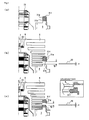
stator blades 30 and the spacer rings 31a to 31h in the turbo-molecular pump 1 in accordance with this embodiment is explained with reference toFigures 4(a) to 4(c) . - For the turbo-molecular pump 1 in accordance with this embodiment, before the rotating section formed by the
shaft 7, therotor body 8, therotor blades 9, and thecylindrical member 10 is attached to the base 24 being the fixed section, of the spacer rings 31a to 31h, the spacer rings having been classified into group B by the above-described method are disposed in advance on the threadedlygrooved spacer 3 in a stacked state. - That is to say, first, as shown in
Figure 4(a) , the spacer rings 31f to 31h of group B are set (disposed) on the threadedlygrooved spacer 3 in a stacked state. - Next, the
shaft 7 of the rotating section is inserted along the bearing section of the base 24 from the upside on the drawing (the intake port 4 side), and the rotating section is fixed to thebase 24, which is the fixed section, by using a nut 25 (refer toFigure 1 ). - Thereafter, as shown in
Figure 4(b) , the spacer rings 31f to 31h are raised (lifted up) to provide a clearance between thespacer ring 31h closest to the exhaust port 6 side and the threadedlygrooved spacer 3. Then, thestator blade 30 divided into two pieces in the circumferential direction, that is, having a halved shape is inserted between therotor blades 9 from the outside in the radial direction through the clearance between thespacer ring 31h and the threadedlygrooved spacer 3. - After the
stator blade 30 has been inserted through the clearance between thespacer ring 31h and the threadedlygrooved spacer 3, as shown inFigure 4(c) , the raising (lifting up) of thespacer ring 31h is released, that is, thespacer ring 31h is lowered, by which the insertedstator blade 30 is held by the threadedlygrooved spacer 3 and thespacer ring 31h, and is fixed. - Successively, the
stator blade 30 having a halved shape is inserted between therotor blades 9 from the outside in the radial direction through a clearance between thespacer ring 31h and thespacer ring 31g, and the insertedstator blade 30 is held by thespacer ring 31g and thespacer ring 31h, and is fixed. - In the same way, the
stator blade 30 is inserted between therotor blades 9 through a clearance between thespacer ring 31g and thespacer ring 31f. - When the clearance is formed to insert the
stator blade 30, it is desirable to use a special-purpose jig to raise the spacer rings 31f to 31h. - Also, in the turbo-molecular pump 1 in accordance with this embodiment, to enable the insertion of the
stator blade 30, the clearance d1 between the threadedlygrooved spacer 3 and thespacer ring 31h, shown inFigure 4(b) , and the clearance d2 between thespacer ring 31h and thespacer ring 31g, shown inFigure 4(c) , are configured so as to take a value larger than the height (thickness) of the insertedstator blade 30. - Although not shown in the drawing, the clearance between the
spacer ring 31g and thespacer ring 31f is also configured so as to take a value larger than the height (thickness) h of the insertedstator blade 30. - The clearance between the
spacer ring 31h and the threadedlygrooved spacer 3 and the clearance between the spacer rings 31f to 31h are movable (variable) clearances formed by raising (lifting up) the spacer rings 31f to 31h. However, the variable range of these clearances is restricted by the movable range of the spacer rings 31f to 31h. - The outside diameters of the
rotor blades 9 down to the fifth stage from the intake port 4 side are formed so as to be larger than the inside diameter of thespacer ring 31f. Therefore, therotor blade 9 in the fifth stage from the intake port 4 side and thespacer ring 31f interfere (come into contact) with each other physically, so that the movable range of thespacer ring 31f is restricted by this portion. - Thus, the movable range of the spacer rings 31f to 31h is restricted by a portion physically interfering (coming into contact) with the
rotor blades 9, theadjacent spacer ring 31f to 31h, the insertedstator blades 30, and the like. - In the turbo-molecular pump 1 in accordance with this embodiment, considering the movable range of the spacer rings 31f to 31h restricted in this manner, the clearance through which the
stator blade 30 is inserted, that is, the clearance between thespacer ring 31h and the threadedlygrooved spacer 3 and each of the clearances between thespacers 31f to 31h is set (designed) so as to be larger than the height (thickness) h of the insertedstator blade 30. - The adjustment (regulation) of the clearance between the
spacer ring 31h and the threadedlygrooved spacer 3 and the clearances between thespacers 31f to 31h can be made by adjusting the interval at which therotor blades 9 are formed, the height (thickness) h of thestator blade 30, the protruding part 34 on thespacer ring 31f to 31h shown inFigure 2 , the height (thickness) and shape of thespacer ring 31f to 31h, and the like. - Specifically, for example, like the
spacer ring 31f shown in the enlarged view inFigure 4(c) , a level difference β is provided in the inner peripheral edge part of the upper surface (surface on the intake port 4 side) to secure (obtain) a distance necessary for preventing the interference (contact) with therotor blade 9. This level difference β functions as an adjusting structure. - Also, as shown in
Figure 5(a) , thespacer ring 31 in the turbo-molecular pump 1 in accordance with this embodiment is formed by a ring-shapedbody part 311 having a rectangular cross section, astep part 312 projecting from the end surface on the exhaust port 6 side of thebody part 311 to the outer periphery, and a projectingpart 313 projecting from thestep part 312 to the exhaust port 6 side. - The projecting
part 313 of theadjacent spacer ring 31 and the outer peripheral wall of thebody part 311 form a holding structure for holding thespacer ring 31 by engagement. - Further, the configuration is made such that the length obtained by adding the thickness (h) of the
stator blade 30 to the length (y) from the end surface on the intake port 4 side of thebody part 311 to the end surface on the intake port 4 side of thestep part 312 is longer than the length (e) of the projectingpart 313. - By configuring the holding structure for the
spacer ring 31 in this manner, a clearance δ is formed between the projectingparts 313 of the adjacent spacer rings 31 as shown inFigure 5(b) when thestator blade 30 is inserted. - In the state in which the
stator blade 30 is not inserted, as shown inFigure 5(b) , a clearance L for inserting thestator blades 30 can be formed properly. - In the holding structure for a spacer ring 31' of the conventional example, as shown in
Figure 5(c) , no clearance is formed between projecting parts 313' of the adjacent spacer rings 31' when thestator blade 30 is inserted, so that the spacer ring 31' cannot be raised to form a clearance for inserting a stator blade 30'. - After the
stator blades 30 have been inserted through the clearance between thespacer ring 31h and the threadedlygrooved spacer 3 and the clearances between the spacer rings 31f to 31h, thestator blade 30 is inserted between therotor blades 9 on the upper surface (the intake port 4 side surface) of thespacer ring 31f from the outside in the radial direction. Then, thespacer ring 31d is fitted from the intake port 4 side to fix thestator blade 30. - That is to say, after the
stator blades 30 have been disposed between the spacer rings 31f to 31h of group B, thestator blade 30 is further inserted from the outside in the radial direction, and the spacer rings 31a to 31d of group A are piled up one after another from the exhaust port 6 side while being fitted along the outside diameters of therotor blades 9 from the intake port 4 side. - A method of piling up (fitting) the spacer rings 31a to 31d of group A is the same as the conventional method.
- After all of the
stator blades 30 and the spacer rings 31a to 31h have been assembled, the casing 2 is installed so as to cover the spacer rings 31a to 31h, and the casing 2 is fixed to the threadedlygrooved spacer 3. The casing 2 is fixed by using fastening members such as thebolts 33, for example, as shown inFigure 3 . - By fixing the casing 2 to the threadedly
grooved spacer 3, the spacer rings 31a to 31h are fixed, and thestator blades 30 are fixedly disposed at proper positions between therotor blades 9. - As described above, in this embodiment, of the spacer rings 31a to 31h, the spacer rings that cannot be fitted from the intake port 4 side because of the interference (contact) with the
rotor blade 9 are disposed on the threadedlygrooved spacer 3 in a stacked state before the rotating section (rotating body) is fixedly disposed on the fixed section (the base 24). - Specifically, the spacer rings 31f to 31h that cannot be fitted from the intake port 4 side because of the interference (contact) with the
rotor blade 9 are disposed in advance on the threadedlygrooved spacer 3, that is, on fixed member (fixed side) on which thespacer ring 31h is disposed. - The turbo-molecular pump 1 in accordance with this embodiment has a construction such that the turbo-molecular pump 1 is not assembled so that the spacer rings 31f to 31h are fitted on the
rotor blades 9 and are stacked, but assembled so that the rotor blades 9 (the rotor body 8) are fitted in the stacked spacer rings 31f to 31h. - Since the turbo-molecular pump 1 in accordance with this embodiment has such a construction, the turbo-molecular pump 1 has a construction such that the outside diameters of the
rotor blades 9 on the exhaust port 6 side are smaller than the outside diameters of therotor blades 9 on the intake port 4 side. However, the spacer rings 31a to 31h that do not have a halved shape (that is, are integral) can be assembled easily. - According to this embodiment, even in the turbo-molecular pump 1 having the construction such that the outside diameters of the
rotor blades 9 on the exhaust port 6 side are smaller than the outside diameters of therotor blades 9 on the intake port 4 side, thestator blades 30 can be assembled (piled up) without the use of spacer rings that are divided into two pieces in the circumferential direction. - That is to say, even in the turbo-molecular pump 1 having the construction such that the outside diameters of the
rotor blades 9 on the exhaust port 6 side are smaller than the outside diameters of therotor blades 9 on the intake port 4 side, the assembling work can be performed one after another from the downside as in the conventional example, so that the assembling ability at the manufacturing time is not decreased. - Also, by using the integral spacer rings 31a to 31h continuous in the circumferential direction, the strength can be improved as compared with the turbo-molecular pump using halved spacer rings. In particular, the strength against breaking torque at the time of abnormality can be improved.
- Further, the integral spacer rings 31a to 31h continuous in the circumferential direction have no possibility of the occurrence of troubles during processing (cutting) such as the deformation of cut surface, the distortion of external shape, and the shift of joint part (mating part), which may occur in the case of the halved spacer ring.
- According to this embodiment, since the construction such that the outside diameters of the
rotor blades 9 on the exhaust port 6 side are smaller than the outside diameters of therotor blades 9 on the intake port 4 side is adopted, the centrifugal stress acting on therotor blade 9 on the downstream side (the exhaust port 6 side) when theshaft 7 rotates at a high speed can be reduced, so that the durability of the turbo-molecular pump 1 can be improved.
Claims (5)
- A turbo-molecular pump comprising:a housing having an intake port and an exhaust port;a rotating body which is enclosed in the housing and has rotor blades of a plurality of stages that are formed so that the outside diameter of at least one stage on the exhaust port side is smaller than that on the intake port side;a rotating shaft pivotally supporting the rotating body;a motor for rotating the rotating shaft;stator blades which are fixed to the housing, being arranged between the rotor blades, and each of which is divided into at least two pieces; andspacer rings each having a ring shape continuous in the circumferential direction which are arranged between the stator blades to hold the stator blades at predetermined intervals, and are formed so that the smallest inside diameter of at least one stage on the exhaust port side is smaller than the largest outside diameter of the rotor blades, characterized in thata clearance between the adjacent spacer rings which is formed in the axial direction when the spacer rings are moved to the intake port side is larger than the thickness of the stator blade.
- The turbo-molecular pump according to claim 1, characterized in that
the spacer ring is formed by a ring-shaped body part having a rectangular cross section, a step part projecting from the end surface on the exhaust port side of the body part to the outer periphery, and a projecting part projecting from the step part to the exhaust port side,
the projecting part of the adjacent spacer ring and the outer peripheral wall of the body part form a holding structure for holding the spacer ring by engagement, and
a length obtained by adding the thickness of the stator blade to the length from the end surface on the intake port side of the body part to the end surface on the intake port side of the step part is longer than the length of the projecting part. - The turbo-molecular pump according to claim 1 or 2, characterized in that an adjusting structure is provided to increase the axial displacement of the spacer ring.
- The turbo-molecular pump according to claim 3, characterized in that the adjusting structure is configured by a level difference which is formed on the inside and on the intake port side of the spacer ring and the inside diameter of which is larger than the outside diameter of the rotor blade.
- A method of assembling a turbo-molecular pump having:a housing having an intake port and an exhaust port;a rotating body which is enclosed in the housing and has rotor blades of a plurality of stages that are formed so that the outside diameter of at least one stage on the exhaust port side is smaller than that on the intake port side;a rotating shaft pivotally supporting the rotating body;a motor for rotating the rotating shaft;stator blades which are fixed to the housing, being arranged between the rotor blades, and each of which is divided into at least two pieces; andspacer rings each having a ring shape continuous in the circumferential direction which are arranged between the stator blades to hold the stator blades at predetermined intervals, and are formed so that the smallest inside diameter of at least one stage on the exhaust port side is smaller than the largest outside diameter of the rotor blades, characterized by comprising:a first step of disposing only the spacer ring having an inside diameter smaller than the largest outer diameter of the rotor blades on the housing or a fixed part fixed to the housing;a second step of inserting the rotating body in the housing;a third step of moving the spacer ring disposed on the fixed part in the first step to the intake port side and thereby forming a clearance between the adjacent spacer rings;a fourth step of inserting the stator blade between the rotor blades from the outside in the radial direction through the clearance between the spacer rings formed in the third step; anda fifth step of moving the spacer ring moved in the third step to the exhaust port side and thereby fixing the stator blade inserted in the fourth step.
Applications Claiming Priority (2)
| Application Number | Priority Date | Filing Date | Title |
|---|---|---|---|
| JP2005181389A JP4749054B2 (en) | 2005-06-22 | 2005-06-22 | Turbomolecular pump and method of assembling turbomolecular pump |
| PCT/JP2006/312108 WO2006137333A1 (en) | 2005-06-22 | 2006-06-16 | Turbo-molecular pump and method of assembling turbo-molecular pump |
Publications (3)
| Publication Number | Publication Date |
|---|---|
| EP1900944A1 true EP1900944A1 (en) | 2008-03-19 |
| EP1900944A4 EP1900944A4 (en) | 2010-03-31 |
| EP1900944B1 EP1900944B1 (en) | 2014-01-15 |
Family
ID=37570363
Family Applications (1)
| Application Number | Title | Priority Date | Filing Date |
|---|---|---|---|
| EP06766796.4A Active EP1900944B1 (en) | 2005-06-22 | 2006-06-16 | Turbo-molecular pump and method of assembling turbo-molecular pump |
Country Status (5)
| Country | Link |
|---|---|
| US (1) | US8366380B2 (en) |
| EP (1) | EP1900944B1 (en) |
| JP (1) | JP4749054B2 (en) |
| KR (1) | KR101204633B1 (en) |
| WO (1) | WO2006137333A1 (en) |
Cited By (2)
| Publication number | Priority date | Publication date | Assignee | Title |
|---|---|---|---|---|
| CN101634307A (en) * | 2008-07-22 | 2010-01-27 | 株式会社大阪真空机器制作所 | Turbo-molecular pump |
| WO2022184739A1 (en) * | 2021-03-04 | 2022-09-09 | Edwards s.r.o. | Stator assembly |
Families Citing this family (10)
| Publication number | Priority date | Publication date | Assignee | Title |
|---|---|---|---|---|
| WO2009028099A1 (en) * | 2007-08-31 | 2009-03-05 | Shimadzu Corporation | Turbo molecular drag pump |
| JP2011027049A (en) * | 2009-07-28 | 2011-02-10 | Shimadzu Corp | Turbo-molecular pump |
| CN102536902A (en) * | 2010-12-13 | 2012-07-04 | 致扬科技股份有限公司 | Improved blade structure of turbo molecular pump |
| JP6433812B2 (en) | 2015-02-25 | 2018-12-05 | エドワーズ株式会社 | Adapter and vacuum pump |
| JP6782141B2 (en) | 2016-10-06 | 2020-11-11 | エドワーズ株式会社 | Vacuum pumps, as well as spiral plates, spacers and rotating cylinders on vacuum pumps |
| JP7088688B2 (en) * | 2018-02-16 | 2022-06-21 | エドワーズ株式会社 | Vacuum pump and vacuum pump controller |
| JP7096006B2 (en) * | 2018-02-16 | 2022-07-05 | エドワーズ株式会社 | Vacuum pump and vacuum pump controller |
| JP2020023949A (en) * | 2018-08-08 | 2020-02-13 | エドワーズ株式会社 | Vacuum pump, cylindrical portion used in vacuum pump, and base portion |
| JP2022035881A (en) | 2020-08-21 | 2022-03-04 | エドワーズ株式会社 | Vacuum pump, fixed blade and spacer |
| JP2023017160A (en) * | 2021-07-26 | 2023-02-07 | エドワーズ株式会社 | Vacuum pump |
Citations (1)
| Publication number | Priority date | Publication date | Assignee | Title |
|---|---|---|---|---|
| US20020076317A1 (en) * | 2000-12-18 | 2002-06-20 | Applied Materials, Inc. | Turbo-molecular pump having enhanced pumping capacity |
Family Cites Families (6)
| Publication number | Priority date | Publication date | Assignee | Title |
|---|---|---|---|---|
| DE2554995A1 (en) * | 1975-12-06 | 1977-06-16 | Pfeiffer Vakuumtechnik | TURBOMOLECULAR PUMP |
| JPH0641798B2 (en) * | 1986-07-29 | 1994-06-01 | 三菱重工業株式会社 | Gas-liquid two-phase fluid distributor |
| JPS6334393U (en) * | 1986-08-20 | 1988-03-05 | ||
| JPH10246197A (en) * | 1997-03-05 | 1998-09-14 | Ebara Corp | Turbo-molecular pump |
| EP1249613B1 (en) * | 2001-03-15 | 2004-01-28 | VARIAN S.p.A. | Turbine pump with a stator stage integrated with a spacer ring |
| JP2003287463A (en) * | 2002-03-28 | 2003-10-10 | Boc Edwards Technologies Ltd | Radiation-temperature measuring apparatus and turbo- molecular pump with the same mounted |
-
2005
- 2005-06-22 JP JP2005181389A patent/JP4749054B2/en active Active
-
2006
- 2006-06-16 KR KR1020077027228A patent/KR101204633B1/en active IP Right Grant
- 2006-06-16 WO PCT/JP2006/312108 patent/WO2006137333A1/en active Application Filing
- 2006-06-16 US US11/922,655 patent/US8366380B2/en active Active
- 2006-06-16 EP EP06766796.4A patent/EP1900944B1/en active Active
Patent Citations (1)
| Publication number | Priority date | Publication date | Assignee | Title |
|---|---|---|---|---|
| US20020076317A1 (en) * | 2000-12-18 | 2002-06-20 | Applied Materials, Inc. | Turbo-molecular pump having enhanced pumping capacity |
Non-Patent Citations (1)
| Title |
|---|
| See also references of WO2006137333A1 * |
Cited By (3)
| Publication number | Priority date | Publication date | Assignee | Title |
|---|---|---|---|---|
| CN101634307A (en) * | 2008-07-22 | 2010-01-27 | 株式会社大阪真空机器制作所 | Turbo-molecular pump |
| CN101634307B (en) * | 2008-07-22 | 2013-06-12 | 株式会社大阪真空机器制作所 | Turbo-molecular pump |
| WO2022184739A1 (en) * | 2021-03-04 | 2022-09-09 | Edwards s.r.o. | Stator assembly |
Also Published As
| Publication number | Publication date |
|---|---|
| WO2006137333A1 (en) | 2006-12-28 |
| KR20080019591A (en) | 2008-03-04 |
| KR101204633B1 (en) | 2012-11-23 |
| US8366380B2 (en) | 2013-02-05 |
| US20090116959A1 (en) | 2009-05-07 |
| JP2007002692A (en) | 2007-01-11 |
| EP1900944B1 (en) | 2014-01-15 |
| JP4749054B2 (en) | 2011-08-17 |
| EP1900944A4 (en) | 2010-03-31 |
Similar Documents
| Publication | Publication Date | Title |
|---|---|---|
| EP1900944B1 (en) | Turbo-molecular pump and method of assembling turbo-molecular pump | |
| EP3415766B1 (en) | Vacuum pump with flexible cover and rotor | |
| EP2644917B1 (en) | Magnetic bearing control device, and exhaust pump provided with the device | |
| US6832888B2 (en) | Molecular pump for forming a vacuum | |
| US8403652B2 (en) | Molecular pump and flange having shock absorbing member | |
| JP5276321B2 (en) | Turbo molecular pump | |
| WO2006068014A1 (en) | Structure for connecting end parts and vacuum system using the structure | |
| EP4006349A1 (en) | Vacuum pump, and rotor and rotary vane for use in vacuum pump | |
| CN107208650B (en) | Adapter and vacuum pump | |
| JP3038432B2 (en) | Vacuum pump and vacuum device | |
| US6607365B1 (en) | Vacuum pump and vacuum apparatus | |
| JP5255752B2 (en) | Turbo molecular pump | |
| CN112469902B (en) | Vacuum pump, and cylinder and base used for the vacuum pump | |
| EP1700039B1 (en) | Vacuum pumping arrangement | |
| CN108626142B (en) | Central ring and vacuum pump | |
| JP2021014800A (en) | Manufacturing method of vacuum pump, vacuum pump and stator for vacuum pump | |
| JP2000274391A (en) | Over hang type turbo molecular pump | |
| JP2006090231A (en) | Method for manufacturing fixed blade of turbo molecular pump and vacuum pump | |
| WO2023237855A1 (en) | Magnetic bearing hub and vacuum pump | |
| KR20230119762A (en) | Turbo molecular pump | |
| CN114026335A (en) | Vacuum pump | |
| EP1072805A2 (en) | Magnetic bearing device |
Legal Events
| Date | Code | Title | Description |
|---|---|---|---|
| PUAI | Public reference made under article 153(3) epc to a published international application that has entered the european phase |
Free format text: ORIGINAL CODE: 0009012 |
|
| 17P | Request for examination filed |
Effective date: 20071224 |
|
| AK | Designated contracting states |
Kind code of ref document: A1 Designated state(s): DE FR GB |
|
| RBV | Designated contracting states (corrected) |
Designated state(s): DE FR GB |
|
| DAX | Request for extension of the european patent (deleted) | ||
| RBV | Designated contracting states (corrected) |
Designated state(s): DE FR GB |
|
| DAX | Request for extension of the european patent (deleted) | ||
| RAP1 | Party data changed (applicant data changed or rights of an application transferred) |
Owner name: EDWARDS JAPAN LIMITED |
|
| A4 | Supplementary search report drawn up and despatched |
Effective date: 20100303 |
|
| 17Q | First examination report despatched |
Effective date: 20100707 |
|
| GRAP | Despatch of communication of intention to grant a patent |
Free format text: ORIGINAL CODE: EPIDOSNIGR1 |
|
| RIC1 | Information provided on ipc code assigned before grant |
Ipc: F04D 29/64 20060101ALI20130812BHEP Ipc: F04D 19/04 20060101AFI20130812BHEP |
|
| INTG | Intention to grant announced |
Effective date: 20130919 |
|
| GRAS | Grant fee paid |
Free format text: ORIGINAL CODE: EPIDOSNIGR3 |
|
| GRAA | (expected) grant |
Free format text: ORIGINAL CODE: 0009210 |
|
| AK | Designated contracting states |
Kind code of ref document: B1 Designated state(s): DE FR GB |
|
| REG | Reference to a national code |
Ref country code: GB Ref legal event code: FG4D |
|
| REG | Reference to a national code |
Ref country code: DE Ref legal event code: R096 Ref document number: 602006040084 Country of ref document: DE Effective date: 20140227 |
|
| REG | Reference to a national code |
Ref country code: DE Ref legal event code: R097 Ref document number: 602006040084 Country of ref document: DE |
|
| PLBE | No opposition filed within time limit |
Free format text: ORIGINAL CODE: 0009261 |
|
| STAA | Information on the status of an ep patent application or granted ep patent |
Free format text: STATUS: NO OPPOSITION FILED WITHIN TIME LIMIT |
|
| 26N | No opposition filed |
Effective date: 20141016 |
|
| REG | Reference to a national code |
Ref country code: DE Ref legal event code: R097 Ref document number: 602006040084 Country of ref document: DE Effective date: 20141016 |
|
| REG | Reference to a national code |
Ref country code: FR Ref legal event code: PLFP Year of fee payment: 11 |
|
| REG | Reference to a national code |
Ref country code: FR Ref legal event code: PLFP Year of fee payment: 12 |
|
| REG | Reference to a national code |
Ref country code: FR Ref legal event code: PLFP Year of fee payment: 13 |
|
| P01 | Opt-out of the competence of the unified patent court (upc) registered |
Effective date: 20230503 |
|
| PGFP | Annual fee paid to national office [announced via postgrant information from national office to epo] |
Ref country code: FR Payment date: 20230510 Year of fee payment: 18 Ref country code: DE Payment date: 20230502 Year of fee payment: 18 |
|
| PGFP | Annual fee paid to national office [announced via postgrant information from national office to epo] |
Ref country code: GB Payment date: 20230427 Year of fee payment: 18 |