EP1900936A1 - Starter of small engine - Google Patents
Starter of small engine Download PDFInfo
- Publication number
- EP1900936A1 EP1900936A1 EP06746492A EP06746492A EP1900936A1 EP 1900936 A1 EP1900936 A1 EP 1900936A1 EP 06746492 A EP06746492 A EP 06746492A EP 06746492 A EP06746492 A EP 06746492A EP 1900936 A1 EP1900936 A1 EP 1900936A1
- Authority
- EP
- European Patent Office
- Prior art keywords
- stopper
- engaging
- spring
- cam plate
- cam
- Prior art date
- Legal status (The legal status is an assumption and is not a legal conclusion. Google has not performed a legal analysis and makes no representation as to the accuracy of the status listed.)
- Granted
Links
Images


Classifications
-
- F—MECHANICAL ENGINEERING; LIGHTING; HEATING; WEAPONS; BLASTING
- F02—COMBUSTION ENGINES; HOT-GAS OR COMBUSTION-PRODUCT ENGINE PLANTS
- F02N—STARTING OF COMBUSTION ENGINES; STARTING AIDS FOR SUCH ENGINES, NOT OTHERWISE PROVIDED FOR
- F02N5/00—Starting apparatus having mechanical power storage
- F02N5/02—Starting apparatus having mechanical power storage of spring type
-
- F—MECHANICAL ENGINEERING; LIGHTING; HEATING; WEAPONS; BLASTING
- F02—COMBUSTION ENGINES; HOT-GAS OR COMBUSTION-PRODUCT ENGINE PLANTS
- F02N—STARTING OF COMBUSTION ENGINES; STARTING AIDS FOR SUCH ENGINES, NOT OTHERWISE PROVIDED FOR
- F02N3/00—Other muscle-operated starting apparatus
- F02N3/02—Other muscle-operated starting apparatus having pull-cords
-
- F—MECHANICAL ENGINEERING; LIGHTING; HEATING; WEAPONS; BLASTING
- F02—COMBUSTION ENGINES; HOT-GAS OR COMBUSTION-PRODUCT ENGINE PLANTS
- F02D—CONTROLLING COMBUSTION ENGINES
- F02D2400/00—Control systems adapted for specific engine types; Special features of engine control systems not otherwise provided for; Power supply, connectors or cabling for engine control systems
- F02D2400/06—Small engines with electronic control, e.g. for hand held tools
-
- F—MECHANICAL ENGINEERING; LIGHTING; HEATING; WEAPONS; BLASTING
- F02—COMBUSTION ENGINES; HOT-GAS OR COMBUSTION-PRODUCT ENGINE PLANTS
- F02N—STARTING OF COMBUSTION ENGINES; STARTING AIDS FOR SUCH ENGINES, NOT OTHERWISE PROVIDED FOR
- F02N11/00—Starting of engines by means of electric motors
Definitions
- This invention relates to an ignition system for small engines which may give sufficient horse power to a horse power spring for engine rotation, by providing a torque limiter with the current ignition systems.
- a small engine ignition system has a drive gear which connects to a tubular cam having a nail engaging to a centrifugal latchet of a pulley fixed to the engine crankshaft with a horse power spring.
- This drive gear is rotated manually or by an electric motor to store energy in the horse power spring, when the energy exceeds the start resistance, the sudden release of the horse power spring starts the engine.
- the engine may be rotated by the horsepower of the horse power spring.
- the start resistance of the engine is at its highest when the piston is at near the top dead center, and at its lowest when the piston is at near the bottom dead center; thus, the start resistance of the engine is unstable. Before enough horsepower is given to the horse power spring and/or sufficient energy is stored, the engine may start to rotate. In this case, the engine may not surely start.
- This invention will solve the problems above and the purpose of the invention is to provide an ignition system for small engines that will enable the engine to surely start by giving enough horsepower to the horse power spring, regardless of the resistance.
- the invention defined as claim 1 is comprised of ; the inside of the starter motor, a cylindrical cam having a cam nail which engages with a pulley centrifugal latchet fixed on the engine crank shaft, and a drive gear connecting to the cylindrical cam via a horse power spring located on the same axis;
- the Ignition system for small engines as defined in claim 2 is comprised of ; the first spring supporting the stopper in a swinging manner to the spindle provided in the starter case, and, around the spindle on both sides of the stopper, urging the stopper to swing to the avoidance position;
- the ignition system for small engines as defined in claim 3 is comprised of; operation means which pulls the second spring from outside enabling operation of the start button of the engine self starter motor.
- the invention defined as claim 4 is comprised of; a long hole being provided in the stopper and a spindle provided in the starter being engaged with the long hole so as to retract the stopper from the engaging position and move to the avoidance position.
- the stopper quickly moves between an avoidance position and an engaging position with the first and second springs.
- the movement operation is also easy.
- the stopper movement and self starter motor start can be performed by single operation. This makes for an efficient operational system.
- the stopper may smoothly retract from the engaging position.
- the ignition system for small engines is a combination of a recoil starter towing the starter rope 2 which is wound around the rope reel 1 and an electric self starter motor 3, the pulley 5 fixed to the engine crank shaft is installed on one side of the starter case 4, a spindle 6 is formed on the same axis of the pulley 5 in the starter case 4 and a cylindrical cam 7 engageable with the pulley 5 and a drive gear 8 which connects to the cylindrical 7 via a horse power spring 11 (spiral spring) are arranged in a freely rotating manner.
- a horse power spring 11 spiral spring
- the cam plate 12 is integrally formed on the periphery of pulley 5.
- the cam 7 is arranged on the pulley 5 side of the drive gear 8, and the cam nail 10 formed on the cam 7 is arranged oppositely to latch with the centrifugal latchet 9 provided on the side surface of pulley 5.
- the centrifugal latchet 9 is urged to always latch with the cam 7 with a spring. Consequently, similarly to the patent publication 1 mentioned earlier, when the cam 7 rotates in one direction, a pulley 5 also rotates since the centrifugal latchet 9 and the cam nail 10 engage with each other, and when the cam 7 rotates in the opposite direction, the cam idles so that the pulley 5 does not rotate.
- a cyclic depressed area 13 is formed on the cam 7 side of the gear of drive gear 8 and the horse power spring 11 is arranged in the cyclic depressed area 13.
- One end of horse power spring 11 latches onto the drive gear 8 and the other end of the horse power spring matches onto the cam 7.
- the nails 14 and 15 are formed on the side surface of the opposite side of cam 7 of the drive gear 8.
- the recoil start and the motor start are structured so as to rotate the drive gear 8.
- the rotation transfer mechanism with its recoil start works in the follow manner; the rope reel 1 is supported in a freely rotating manner at the opposite side of the cam 7 on the spindle 6 of the drive gear 8.
- the rope groove 16 is formed on the periphery of the rope reel 1, and the disk area 17 is formed on the inner periphery.
- the starter rope 2 is wound in the rope groove 16, one end of the starter cord 2a is pulled outside of the starter case 4 and end of a base side is fixed at the rope reel 1 being pulled outside of the bottom hole (not shown) of the groove 16 to prevent it from coming off.
- the starter rope 2a By pulling the one end of the starter cord 2a, the starter rope 2 is pulled out from the rope reel 1 and the rope reel 1 rotates and drives around a reel spindle 6.
- a disk 19 which is equipped with the latchet nail 15 attaching and detaching to the latchet nail 14 of the drive gear 8 is provided in a movable manner, and is urged to always engage with the ratchet nail 14 of the drive gear with a compressive spring 18.
- the disk 19 is provided in a movable manner along a cylindrical part 1a of inner periphery of the rope reel 1.
- the mechanism of rotation transfer to the drive gear 8 with the self starter motor 3 is composed of two reducing gears. That is, the first reducing gear 23 is meshed and connected to the gear 2 of the self starter motor 3(driven by a battery) output shaft 21, the second reducing gear 24 is meshed and connected to small-diameter gear 23a of the fist reducing gear 23, and the second reducing gear 24 meshes with the periphery gear 25.
- the second reducing gear 24 meshing with the drive gear 8 is divided into the small-diameter gear 24a and large-diameter gear 24b, and both gears are supported in a freely rotating manner on the common rotation axis 26.
- the small-diameter 24a meshes with the drive gear 8
- the large-diameter gear 24b meshes with the small-diameter gear 23a of the reducing gear 23.
- the large-diameter gear 24b moves along the rotation axis 26 and is arranged in a detachable manner to the small-diameter 24a.
- each engaging nail 27 and 28 are formed respectively on the side surface, facing the small-diameter gear 24a and the large-diameter gear 24b each other.
- one side of the circumferential direction of each engaging nail (27) and (28) is inclined and the other side is formed vertically against the side surface.
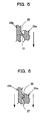
- engaging nails 27 and 28 rotate in the same direction, they engage each of their vertical surfaces and both gears rotate, and when the engaging nails rotate in the opposite direction, as shown in Fig. 6 , each inclined surface abuts, not engages, and either of the gears idles.
- the compressive spring 29 is arranged between the starter case 4 and large-diameter gear 24b, the large-diameter is pressed toward the small-diameter gear 24a by the compressive spring 29, and the side surface of the large-diameter gear 24b and the small-diameter gear 24a is urged to contact to each other.
- the cam plate 12 which is integrally formed with the pulley 5 is comprised of having a depressed area 30 formed on the rim of the disk, and the stopper 31 is arranged near the cam plate 12.
- the stopper 31 is an elongated plate-like body, has an engageable engaging 31 a at the end 32 (engaging end) behind the rotation direction of the cam plate 12 depressed area 30, a long hole 33 is also created at the center of the stopper 31, and the spindle 39 provided in the ignition case 4 engages with the long hole 33.
- the stopper 31 may swing around the spindle 39, an engaging pin 34 is provided on both sides of the stopper 31 of the starter case, and the stopper 31 may swing until the stopper 31 engages with the pin 34. That is, the stopper 31 is supported in a swinging manner to the avoidance position (the position shown in Fig. 8 ) where the engaging 31a avoids the rim of the cam plate 12 and the engaging position (the position shown in Fig. 8 ) where the engaging 31 a engages with the engaging end 32 of the cam plate.
- the first spring 35 which urges the stopper 31 to swing to the avoidance position and the second spring 36 which urges the stopper 31 to swing to the engaging position are arranged.
- the stopper 31 is urged to move to the avoidance position where the engaging 31a does not engage with the engaging end 32 of the cam plate 12 with the first spring 35.
- the end of the first spring 35 is fixed to the starter case 4, and the second spring 36 end is installed in the limiter button 38 (operation means) installed outside of the wall 37 of the starter case 4 via the wire 43.
- the limiter button 38 is installed detachably from the wall 37, pulling the limiter button 38 pull the second spring 36, and the stopper 31 may swing to the engaging position against the first spring 35.
- the third spring 40 (urging means) is arranged at the end of the opposite side of the engaging 31 a of the spindle 39 and the stopper 31.
- the stopper 31 is arranged in a movable manner to the position where the engaging 31a engages with the engaging end 32 of the cam plate, and the retracting position (the position shown in Fig. 12 ) where the engaging 31 a retracts from the engaging position and the engaging is released.
- the retracting is performed with the stopper engaged with the cam plate when sufficient rotation resistance is added to the cam plate and the cam plate cannot bear the load, and the stopper moves to the avoidance position with the first spring.
- the limiter button 38 as shown in Fig. 9 (a) , has a guard 42 on one side of the cylindrical part 41 and one end of the wire 43 is fixed to the cylindrical part. Inside the cylindrical part 41, the axis 45 of the start button 44 for the self starter motor is fitted in a swinging manner.
- conditions can be divided into four categories; when the limiter button 38 and the motor starter button 44 are pulled (as shown in Fig. 9(a) ), or when only the limiter button 38 is pulled (as shown in Fig. 9(b) ), or when neither of the limiter button 38 nor the motor starter button 44 is pulled (as shown in Fig. 8 ).
- the drive gear 8 also continues rotating and the horse power spring 11 is more strongly wound and fastened; hence, the rotary force from the cam to the cam plate 12 increases.
- the stopper 31 cannot resist the load, and, as shown in Fig.12 , the stopper retracts against the spring power of the spring 40 and moves to the initial position as shown in Fig. 8 by being swung by the first spring 35.
- the stopper 31 comes off from the cam plate 12, the energy stored in the horse power spring is released suddenly, the cam 7, the cam plate 12 and the pulley 5 rotate, and the engine connected to the pulley 5 starts to rotate at high speed.
- the large-diameter gear 24b Because of the reduction rate, since the torque which rotates the large-diameter gear 24b is greater than the spring power of the compressive spring 29, the large-diameter gear 24b is locked and moves on a rotation axis 26 to secede from the small-diameter gear 24a against the compressive spring 29; hence, only the small-diameter 24a idles and the rotary force of the drive gear 8 is not transmitted to the large-diameter gear 24b.
- the start resistance and rotation resistance due to the stopper 31 are added to the cam plate 12; hence energy is sufficiently stored due to the rotation of the drive gear 8 in the horse power spring 11, which surely start the engine.
- the self starter motor start or the recoil start is selectively performed in the above example.
- this invention is not limited to the examples. Either start method can be applied.
- the stopper adding the rotation resistance to the cam plate is not limited to the mentioned above.
- the structure, a spring 41 engages a spherical shape to the depressed area 42 of the cam plate 12, may be applied.
Abstract
Description
- This invention relates to an ignition system for small engines which may give sufficient horse power to a horse power spring for engine rotation, by providing a torque limiter with the current ignition systems.
- Generally, a small engine ignition system has a drive gear which connects to a tubular cam having a nail engaging to a centrifugal latchet of a pulley fixed to the engine crankshaft with a horse power spring. This drive gear is rotated manually or by an electric motor to store energy in the horse power spring, when the energy exceeds the start resistance, the sudden release of the horse power spring starts the engine.
[Patent publication 1] Patent publication2002-227753 Official bulletin - If the energy exceeding the start resistance is then stored in the horse power spring, the engine may be rotated by the horsepower of the horse power spring.
- However, the start resistance of the engine is at its highest when the piston is at near the top dead center, and at its lowest when the piston is at near the bottom dead center; thus, the start resistance of the engine is unstable. Before enough horsepower is given to the horse power spring and/or sufficient energy is stored, the engine may start to rotate. In this case, the engine may not surely start.
- This invention will solve the problems above and the purpose of the invention is to provide an ignition system for small engines that will enable the engine to surely start by giving enough horsepower to the horse power spring, regardless of the resistance.
- In order to solve these problems, the invention defined as
claim 1 is comprised of ; the inside of the starter motor, a cylindrical cam having a cam nail which engages with a pulley centrifugal latchet fixed on the engine crank shaft, and a drive gear connecting to the cylindrical cam via a horse power spring located on the same axis; - a stopper being arranged near a cam plate which is integrally formed with the pulley, and
- having an engageable engaging with the end part behind the rotation direction of the cam plate depressed area;
- urging means supporting the stopper in movable manner to an engaging position where the engaging engages with the depressed area and to an avoidance position for avoiding the cam plate rim, and normally urging to move the stopper to the avoidance position, on the other hand enabling the stopper to move the engaging position from outside, and urging not to move the stopper to the avoidance position until a sufficient rotation load is added to the cam plate at the engaging position.
- The Ignition system for small engines as defined in
claim 2 is comprised of ; the first spring supporting the stopper in a swinging manner to the spindle provided in the starter case, and, around the spindle on both sides of the stopper, urging the stopper to swing to the avoidance position; - the second spring urging the stopper to swing to the engaging position;
- enabling to move the stopper to the engaging position by pulling the second spring from the outside.
- The ignition system for small engines as defined in
claim 3 is comprised of; operation means which pulls the second spring from outside enabling operation of the start button of the engine self starter motor. - The invention defined as
claim 4 is comprised of; a long hole being provided in the stopper and a spindle provided in the starter being engaged with the long hole so as to retract the stopper from the engaging position and move to the avoidance position. - According to the invention defined in
claim 1, since the start resistance of the engine and rotational resistance due to a stopper are added to the cam plate during ignition of the engine,
sufficient energy is stored in the horse power spring due to the drive gear rotation. Since the engine is rotated releasing sufficient energy, the engine can surely tart. - According to the invention defined in
claim 2, the stopper quickly moves between an avoidance position and an engaging position with the first and second springs. The movement operation is also easy. - According to the invention defined in
claim 3, the stopper movement and self starter motor start can be performed by single operation. This makes for an efficient operational system. - According to the invention defined in
claim 4, the stopper may smoothly retract from the engaging position. - Hereinafter, embodiments of the present invention will be described with referent to the drawings. In
Fig. 1 andFig. 2 , the ignition system for small engines is a combination of a recoil starter towing thestarter rope 2 which is wound around therope reel 1 and an electricself starter motor 3, thepulley 5 fixed to the engine crank shaft is installed on one side of thestarter case 4, a spindle 6 is formed on the same axis of thepulley 5 in thestarter case 4 and acylindrical cam 7 engageable with thepulley 5 and adrive gear 8 which connects to the cylindrical 7 via a horse power spring 11 (spiral spring) are arranged in a freely rotating manner. - The
cam plate 12 is integrally formed on the periphery ofpulley 5. - The
cam 7 is arranged on thepulley 5 side of thedrive gear 8, and thecam nail 10 formed on thecam 7 is arranged oppositely to latch with thecentrifugal latchet 9 provided on the side surface ofpulley 5. Thecentrifugal latchet 9 is urged to always latch with thecam 7 with a spring. Consequently, similarly to thepatent publication 1 mentioned earlier, when thecam 7 rotates in one direction, apulley 5 also rotates since thecentrifugal latchet 9 and thecam nail 10 engage with each other, and when thecam 7 rotates in the opposite direction, the cam idles so that thepulley 5 does not rotate. When rotation of thepulley 5 rotates the engine, and the rotation of the engine rotates thepulley 5, thecentrifugal latchet 9 rotates in the direction that unlatches thecentrifugal latchet 9 from thecam nail 10 due to centrifugal force, so that rotation transfer with thecam 7 of the engine is blocked. - A cyclic
depressed area 13 is formed on thecam 7 side of the gear ofdrive gear 8 and thehorse power spring 11 is arranged in the cyclicdepressed area 13. One end ofhorse power spring 11 latches onto thedrive gear 8 and the other end of the horse power spring matches onto thecam 7. Thus, when thedrive gear 8 rotates, thehorse power spring 11 is wound and the rotary force is stored in thehorse power spring 11, and when sufficient horsepower is stored, thecam 7 starts to rotate. Thenails cam 7 of thedrive gear 8. - The recoil start and the motor start are structured so as to rotate the
drive gear 8. - The rotation transfer mechanism with its recoil start works in the follow manner; the
rope reel 1 is supported in a freely rotating manner at the opposite side of thecam 7 on the spindle 6 of thedrive gear 8. Therope groove 16 is formed on the periphery of therope reel 1, and thedisk area 17 is formed on the inner periphery. Thestarter rope 2 is wound in therope groove 16, one end of the starter cord 2a is pulled outside of thestarter case 4 and end of a base side is fixed at therope reel 1 being pulled outside of the bottom hole (not shown) of thegroove 16 to prevent it from coming off. By pulling the one end of the starter cord 2a, thestarter rope 2 is pulled out from therope reel 1 and therope reel 1 rotates and drives around a reel spindle 6. In thedisc store 17, adisk 19 which is equipped with thelatchet nail 15 attaching and detaching to thelatchet nail 14 of thedrive gear 8 is provided in a movable manner, and is urged to always engage with theratchet nail 14 of the drive gear with acompressive spring 18. Thedisk 19 is provided in a movable manner along acylindrical part 1a of inner periphery of therope reel 1. - Next, the mechanism of rotation transfer to the
drive gear 8 with theself starter motor 3 is composed of two reducing gears. That is, the first reducinggear 23 is meshed and connected to thegear 2 of the self starter motor 3(driven by a battery)output shaft 21, the second reducinggear 24 is meshed and connected to small-diameter gear 23a of thefist reducing gear 23, and the second reducinggear 24 meshes with theperiphery gear 25. The second reducinggear 24 meshing with thedrive gear 8 is divided into the small-diameter gear 24a and large-diameter gear 24b, and both gears are supported in a freely rotating manner on thecommon rotation axis 26. The small-diameter 24a meshes with thedrive gear 8, and the large-diameter gear 24b meshes with the small-diameter gear 23a of the reducinggear 23. The large-diameter gear 24b moves along therotation axis 26 and is arranged in a detachable manner to the small-diameter 24a. - On the side surface, facing the small-
diameter gear 24a and the large-diameter gear 24b each other, threeengaging nails Fig. 3 (a), (b) and Fig. 4 (a), (b) , one side of the circumferential direction of each engaging nail (27) and (28) is inclined and the other side is formed vertically against the side surface. As shown inFig. 5 , when engagingnails Fig. 6 , each inclined surface abuts, not engages, and either of the gears idles. Thecompressive spring 29 is arranged between thestarter case 4 and large-diameter gear 24b, the large-diameter is pressed toward the small-diameter gear 24a by thecompressive spring 29, and the side surface of the large-diameter gear 24b and the small-diameter gear 24a is urged to contact to each other. - As shown in
Fig. 7 andFig. 8 , thecam plate 12 which is integrally formed with thepulley 5 is comprised of having adepressed area 30 formed on the rim of the disk, and thestopper 31 is arranged near thecam plate 12. Thestopper 31 is an elongated plate-like body, has an engageable engaging 31 a at the end 32 (engaging end) behind the rotation direction of thecam plate 12depressed area 30, along hole 33 is also created at the center of thestopper 31, and thespindle 39 provided in theignition case 4 engages with thelong hole 33. - The
stopper 31 may swing around thespindle 39, anengaging pin 34 is provided on both sides of thestopper 31 of the starter case, and thestopper 31 may swing until thestopper 31 engages with thepin 34. That is, thestopper 31 is supported in a swinging manner to the avoidance position (the position shown inFig. 8 ) where the engaging 31a avoids the rim of thecam plate 12 and the engaging position (the position shown inFig. 8 ) where the engaging 31 a engages with theengaging end 32 of the cam plate. - On the both sides of the
stopper 31, thefirst spring 35 which urges thestopper 31 to swing to the avoidance position and thesecond spring 36 which urges thestopper 31 to swing to the engaging position are arranged. Thestopper 31 is urged to move to the avoidance position where the engaging 31a does not engage with theengaging end 32 of thecam plate 12 with thefirst spring 35. - The end of the
first spring 35 is fixed to thestarter case 4, and thesecond spring 36 end is installed in the limiter button 38 (operation means) installed outside of thewall 37 of thestarter case 4 via thewire 43. Thelimiter button 38 is installed detachably from thewall 37, pulling thelimiter button 38 pull thesecond spring 36, and thestopper 31 may swing to the engaging position against thefirst spring 35. - Next, the third spring 40 (urging means) is arranged at the end of the opposite side of the engaging 31 a of the
spindle 39 and the stopper 31.Thus, within the area where the both ends of thelong hole 33 engages with thespindle 39, thestopper 31 is arranged in a movable manner to the position where the engaging 31a engages with theengaging end 32 of the cam plate, and the retracting position (the position shown inFig. 12 ) where the engaging 31 a retracts from the engaging position and the engaging is released. The retracting is performed with the stopper engaged with the cam plate when sufficient rotation resistance is added to the cam plate and the cam plate cannot bear the load, and the stopper moves to the avoidance position with the first spring. - The
limiter button 38, as shown inFig. 9 (a) , has aguard 42 on one side of thecylindrical part 41 and one end of thewire 43 is fixed to the cylindrical part. Inside thecylindrical part 41, theaxis 45 of thestart button 44 for the self starter motor is fitted in a swinging manner. Hence, according to the switch button structure, conditions can be divided into four categories; when thelimiter button 38 and themotor starter button 44 are pulled (as shown inFig. 9(a) ), or when only thelimiter button 38 is pulled (as shown inFig. 9(b) ), or when neither of thelimiter button 38 nor themotor starter button 44 is pulled (as shown inFig. 8 ). - Next, operation function of the ignition system with the said structure is explained.
- When the engine is started with the
self starter motor 3, as shown inFig. 9 (a) , thelimiter button 38 and themotor start button 44 are pulled. With the operation of the motor start button, as shown inFig. 2 , electricity is supplied from a battery to theself starter motor 3, and the rotary force is transmitted to the large-diameter gear 24b of the second reducinggear 24 from thegear 22 fixed on theoutput shaft 21 through the first reducinggear 23. Since the large-diameter gear 24b is pressed against the small-diameter 24a with acompressive spring 29 and when the large-diameter gear 24b rotates, in the direction shown inFig. 2 , engaging nails of the small-diameter gear 24a and the large-diameter gear 24b engage with each other; hence, the small-diameter gear 24a rotates, the rotary force is transmitted to thedrive gear 8 and thedrive gear 8 rotates. When thedrive gear 8 rotates, the load to thecam 7 becomes large since the rotation resistance increases due to the engine start resistance, thehorse power spring 11 is wound and fasten. Since the engine rotation resistance is small at first, when a sufficient amount of energy is stored in thehorse power spring 11, the cam rotates and thecam plate 12 integrally formed with thepulley 5 rotates via thecentrifugal latchet 9. - With the operation of the
limiter button 38, in addition to the engine start resistance, rotation resistance of thecam plate 12 with thestopper 31 is also added to the cam. That is, by pulling thelimiter button 38, as shown inFig. 10 , spring power of thesecond spring 36 becomes larger than that of thefirst spring 35, and the stopper is urged to swing toward the right rotation direction of the figure. In this situation, after the self starter motor start button is turned on as stated above, as stated above, when thecam plate 12 rotates and thedepressed area 30 passes through thestopper 31, thestopper 31 quickly swings to the engaging position as shown inFig. 11 through the status as shown inFig. 10 ., and the engaging 31a of the tip end of thestopper 31 with the engaging 32 behind thedepressed area 30 of thecam plate 12; hence, thecam plate 12 stops since the rotation resistance due to thestopper 31 is added. The engine rotation also stops. This stop position is at the compression top dead center of the piston, and the position almost matches with the position where the rotation resistance is at maximum when the air-fuel mixture is compressed. - Since the
self starter motor 3 continues rotating, thedrive gear 8 also continues rotating and thehorse power spring 11 is more strongly wound and fastened; hence, the rotary force from the cam to thecam plate 12 increases. When the energy stored in thehorse power spring 11 exceeds the rotation resistance against thecam plate 12, which is the sum of the engine rotation resistance and rotation deterrent force, thestopper 31 cannot resist the load, and, as shown inFig.12 , the stopper retracts against the spring power of thespring 40 and moves to the initial position as shown inFig. 8 by being swung by thefirst spring 35. When thestopper 31 comes off from thecam plate 12, the energy stored in the horse power spring is released suddenly, thecam 7, thecam plate 12 and thepulley 5 rotate, and the engine connected to thepulley 5 starts to rotate at high speed. - When the
drive gear 8 rotates as described above, in the rotation direction, as shown inFig. 2 andFig. 5 , each inclined surface of thelatchet nail 14 of thedrive gear 8 and thelatchet nail 15 of thedisk 19 of therope reel 1 contact, the nails override against thecompressive spring 18, the nails do not engage and are separated; rotary force of thedrive gear 8 is not transmitted to therope reel 1. - Next, when the engine is started with the recoil start, as shown in
Fig. 9 (b) , only thelimiter button 38 is pulled, astarter rope 1 is dragged to rotate therope reel 1. As shown inFig. 7 , since thelatchet nail 15 of thedisk 19 and thelatchet nail 14 of thedrive gear 8 are urged to engage with each other with thecompressive spring 18, thedrive gear 8 rotates. When thedrive gear 8 rotates, as described above, energy is stored in thehorse power spring 11, the energy is then released suddenly, thecam 7, thecam plate 12, and thepulley 5 rotate, simultaneously, the engine connected to thepulley 5 rotates at high speed and starts to run. - When the engine starts with the recoil start, the
drive gear 8 rotates, this rotation is transmitted to the small-diameter gear 24a of the second reducinggear 24; hence the small-diameter gear 24a rotates. However, in the case of this rotation direction, as shown inFig. 5 andFig. 7 , each inclined surface of the engagingnails diameter gear 24a and large-diameter gear 24b contact and override, so that thenails diameter gear 24b is greater than the spring power of thecompressive spring 29, the large-diameter gear 24b is locked and moves on arotation axis 26 to secede from the small-diameter gear 24a against thecompressive spring 29; hence, only the small-diameter 24a idles and the rotary force of thedrive gear 8 is not transmitted to the large-diameter gear 24b. - As stated above, to start the engine, the start resistance and rotation resistance due to the
stopper 31 are added to thecam plate 12; hence energy is sufficiently stored due to the rotation of thedrive gear 8 in thehorse power spring 11, which surely start the engine. - The self starter motor start or the recoil start is selectively performed in the above example. However, this invention is not limited to the examples. Either start method can be applied.
- The stopper adding the rotation resistance to the cam plate is not limited to the mentioned above. For example, the structure, a
spring 41 engages a spherical shape to thedepressed area 42 of thecam plate 12, may be applied. -
- [
Fig. 1 ]Front view of the starter of the present invention - [
Fig. 2 ] Vertical cross-section drawing of the starter. - [
Fig. 3 ] (a) and (b) show the front view of the small-diameter gear and cross-section drawing of a-a line respectively. - [
Fig. 4 ] (a) and (b) show the front view of small-diameter gear and cross-section drawing on b-b line respectively. - [
Fig. 5 ] Cross-section diagram which shows nails of small-diameter gear and large-diameter ear engages with each other. - [
Fig. 6 ] Cross-section diagram which shows nails of small-diameter gear and large-diameter gear do not engage with each other. - [
Fig. 7 ] Vertical cross-section diagram of the starter during recoil start - [
Fig. 8 ] Illustration viewed from the front which shows the status where the stopper is at the avoidance position against the cam plate. - [
Fig. 9 ] (a) and (b) show operation function of the limiter button and the motor start button - [
Fig. 10 ] Illustration which shows the stopper is moving to the engaging position. - [
Fig. 11 ] Illustration whish shows the stopper in the engaging position. - [
Fig. 12 ] Illustration which shows the stopper is pushed out from the engaging position and retracts. - [
Fig. 13 ] Simplified illustration which shows another example of the cam plate and the stopper. -
- 11
- Horse power spring
- 12
- Cam plate
- 30
- Depressed area
- 31
- Stopper
- 40
- Urging means (spring)
Claims (4)
- The ignition system for small engines is comprised of; the inside of the starter case, a cylindrical cam having a cam nail which engages with a pulley centrifugal latchet fixed on the engine crank shaft, and a drive gear connecting to the cylindrical cam via a horse power spring located on the same axis;
a stopper being arranged near a cam plate which is integrally formed with the pulley, and having an engageable engaging with the end part behind the rotation direction of the cam plate depressed area;
urging means supporting the stopper in movable manner to an engaging position where the engaging engages with the depressed area and to an avoidance position for avoiding the cam plate rim, and normally urging to move the stopper to the avoidance position, on the other hand enabling the stopper to move to the engaging position from outside, and urging not to move the stopper to the avoidance position until a sufficient rotation load is added to the cam plate at the engaging position. - The Ignition system for small engines as defined in claim 1 is comprised of ; the first spring supporting the stopper in a swinging manner to the spindle provided in the starter case, and, around the spindle on both sides of the stopper, urging the stopper to swing to the avoidance position;
the second spring urging the stopper to swing to the engaging position;
enabling to move the stopper to the engaging position by pulling the second spring from the outside. - The ignition system for small engines as defined in claim 2 is comprised of; operation means which pulls the second spring from outside enabling operation of the start button of the engine self starter motor.
- The ignition system for small engines as defined in claim 1 or claim 2 is comprised of; a long hole being provided in the stopper and a spindle provided in the starter being engaged with the long hole so as to retract the stopper from the engaging position and move to the avoidance position.
Applications Claiming Priority (2)
| Application Number | Priority Date | Filing Date | Title |
|---|---|---|---|
| JP2005168684A JP4667125B2 (en) | 2005-06-08 | 2005-06-08 | Small engine starter |
| PCT/JP2006/309789 WO2006132061A1 (en) | 2005-06-08 | 2006-05-17 | Starter of small engine |
Publications (3)
| Publication Number | Publication Date |
|---|---|
| EP1900936A1 true EP1900936A1 (en) | 2008-03-19 |
| EP1900936A4 EP1900936A4 (en) | 2015-06-17 |
| EP1900936B1 EP1900936B1 (en) | 2018-12-19 |
Family
ID=37498266
Family Applications (1)
| Application Number | Title | Priority Date | Filing Date |
|---|---|---|---|
| EP06746492.5A Active EP1900936B1 (en) | 2005-06-08 | 2006-05-17 | Starter of small engine |
Country Status (5)
| Country | Link |
|---|---|
| US (1) | US7721698B2 (en) |
| EP (1) | EP1900936B1 (en) |
| JP (1) | JP4667125B2 (en) |
| CN (1) | CN101203672B (en) |
| WO (1) | WO2006132061A1 (en) |
Cited By (3)
| Publication number | Priority date | Publication date | Assignee | Title |
|---|---|---|---|---|
| CN102003321A (en) * | 2009-08-29 | 2011-04-06 | 星天具工业株式会社 | Recoil starter |
| EP2365208A3 (en) * | 2010-01-29 | 2013-05-29 | Starting Industrial Co., Ltd. | Starter for small engine |
| GB2518500A (en) * | 2013-07-18 | 2015-03-25 | Andraes Reichart | Starter Unit For a Mobile Device with a Internal Combustion Engine |
Families Citing this family (6)
| Publication number | Priority date | Publication date | Assignee | Title |
|---|---|---|---|---|
| JP4540576B2 (en) * | 2004-09-24 | 2010-09-08 | 昭和機器工業株式会社 | Locking energy storage starter |
| JP5269682B2 (en) * | 2009-04-15 | 2013-08-21 | スターテング工業株式会社 | Small engine starter |
| WO2013015779A2 (en) * | 2011-07-25 | 2013-01-31 | Husqvarna Consumer Outdoor Products Na, Inc. | Starting system for an engine |
| CN102975618A (en) * | 2012-12-06 | 2013-03-20 | 王磊 | Spring force storage method and force storage booster for pulley spring sets |
| CN103912430B (en) * | 2014-04-25 | 2015-12-02 | 熊世民 | Put-put and miniature diesel engine manual cranking device |
| CN110547830B (en) * | 2019-09-17 | 2022-07-19 | 哈尔滨理工大学 | Rotary biopsy gun |
Family Cites Families (11)
| Publication number | Priority date | Publication date | Assignee | Title |
|---|---|---|---|---|
| US2042841A (en) * | 1934-10-18 | 1936-06-02 | Oluf Mikkelsen | Self starter for outboard motors |
| AT377832B (en) * | 1978-12-04 | 1985-05-10 | Bombardier Rotax Gmbh | RETURN STARTER FOR COMBUSTION ENGINES |
| US5083534A (en) * | 1989-04-05 | 1992-01-28 | Mitsubishi Jukogyo Kabushiki Kaisha | Spiral spring type starter apparatus for an internal combustion engine |
| JPH07174061A (en) * | 1993-05-07 | 1995-07-11 | Nitsukari:Kk | Force storage type recoil starter |
| CN1143058C (en) * | 1999-08-06 | 2004-03-24 | 本田技研工业株式会社 | Starter for engine |
| US6508220B1 (en) * | 1999-08-25 | 2003-01-21 | Kioritz Corporation | Starter |
| JP4017792B2 (en) * | 1999-08-25 | 2007-12-05 | 株式会社共立 | Accumulated starter device |
| JP4270426B2 (en) | 2001-01-31 | 2009-06-03 | スターテング工業株式会社 | Engine starter |
| JP2003247477A (en) * | 2002-02-20 | 2003-09-05 | Starting Ind Co Ltd | Recoil starter |
| JP2004068639A (en) * | 2002-08-02 | 2004-03-04 | Showa Kiki Kogyo Kk | Lock-type power accumulation starter |
| JP4022456B2 (en) * | 2002-09-19 | 2007-12-19 | 株式会社クボタ | Engine recoil starter |
-
2005
- 2005-06-08 JP JP2005168684A patent/JP4667125B2/en active Active
-
2006
- 2006-05-17 US US11/921,791 patent/US7721698B2/en active Active
- 2006-05-17 CN CN2006800206949A patent/CN101203672B/en active Active
- 2006-05-17 EP EP06746492.5A patent/EP1900936B1/en active Active
- 2006-05-17 WO PCT/JP2006/309789 patent/WO2006132061A1/en active Application Filing
Non-Patent Citations (1)
| Title |
|---|
| See references of WO2006132061A1 * |
Cited By (7)
| Publication number | Priority date | Publication date | Assignee | Title |
|---|---|---|---|---|
| CN102003321A (en) * | 2009-08-29 | 2011-04-06 | 星天具工业株式会社 | Recoil starter |
| EP2299103A3 (en) * | 2009-08-29 | 2012-04-18 | Starting Industrial Co., Ltd. | Recoil starter |
| US8616170B2 (en) | 2009-08-29 | 2013-12-31 | Starting Industrial Co., Ltd. | Recoil starter |
| CN102003321B (en) * | 2009-08-29 | 2014-12-03 | 星天具工业株式会社 | Recoil starter |
| EP2365208A3 (en) * | 2010-01-29 | 2013-05-29 | Starting Industrial Co., Ltd. | Starter for small engine |
| GB2518500A (en) * | 2013-07-18 | 2015-03-25 | Andraes Reichart | Starter Unit For a Mobile Device with a Internal Combustion Engine |
| GB2518500B (en) * | 2013-07-18 | 2016-01-06 | Andreas Reichart | Starter Unit For a Mobile Device with an Internal Combustion Engine |
Also Published As
| Publication number | Publication date |
|---|---|
| US7721698B2 (en) | 2010-05-25 |
| JP4667125B2 (en) | 2011-04-06 |
| WO2006132061A1 (en) | 2006-12-14 |
| EP1900936B1 (en) | 2018-12-19 |
| CN101203672A (en) | 2008-06-18 |
| EP1900936A4 (en) | 2015-06-17 |
| US20090095246A1 (en) | 2009-04-16 |
| JP2006342717A (en) | 2006-12-21 |
| CN101203672B (en) | 2011-08-03 |
Similar Documents
| Publication | Publication Date | Title |
|---|---|---|
| EP1900936B1 (en) | Starter of small engine | |
| US7201130B2 (en) | Recoil starter | |
| US5537966A (en) | Power storage type recoil starter | |
| JP5424009B2 (en) | Fastener driving machine | |
| US11008994B2 (en) | Engine starter attachments for drill/driver gun | |
| US9797359B2 (en) | Starting device for an internal combustion engine | |
| WO2007046179A1 (en) | Starter for small-sized engine | |
| KR19980702392A (en) | Mechanical starting motor | |
| CN109083793B (en) | Starting disc of internal combustion engine | |
| CN102787958A (en) | Accumulation buffering starter of engine | |
| CN215358270U (en) | Fastener driver | |
| CN102877998A (en) | Mini-tiller starter | |
| JP2532927B2 (en) | Starter for small engines | |
| EP2846034A1 (en) | Starter unit for a mobile device with an internal combustion engine | |
| CN102877999A (en) | Starter of micro-tillage machine | |
| CN202673530U (en) | Power accumulating buffer starter for engine | |
| JP3802393B2 (en) | Engine starter | |
| CN202970999U (en) | Starter of mini-tiller | |
| WO2013015779A2 (en) | Starting system for an engine | |
| JPS6251755A (en) | Recoil starter device for vehicle |
Legal Events
| Date | Code | Title | Description |
|---|---|---|---|
| PUAI | Public reference made under article 153(3) epc to a published international application that has entered the european phase |
Free format text: ORIGINAL CODE: 0009012 |
|
| 17P | Request for examination filed |
Effective date: 20080104 |
|
| AK | Designated contracting states |
Kind code of ref document: A1 Designated state(s): AT BE BG CH CY CZ DE DK EE ES FI FR GB GR HU IE IS IT LI LT LU LV MC NL PL PT RO SE SI SK TR |
|
| DAX | Request for extension of the european patent (deleted) | ||
| RA4 | Supplementary search report drawn up and despatched (corrected) |
Effective date: 20150519 |
|
| RIC1 | Information provided on ipc code assigned before grant |
Ipc: F02N 11/00 20060101ALN20150512BHEP Ipc: F02N 3/02 20060101ALI20150512BHEP Ipc: F02N 5/02 20060101AFI20150512BHEP |
|
| STAA | Information on the status of an ep patent application or granted ep patent |
Free format text: STATUS: EXAMINATION IS IN PROGRESS |
|
| 17Q | First examination report despatched |
Effective date: 20171205 |
|
| RIC1 | Information provided on ipc code assigned before grant |
Ipc: F02N 11/00 20060101ALN20180530BHEP Ipc: F02N 5/02 20060101AFI20180530BHEP Ipc: F02N 3/02 20060101ALI20180530BHEP |
|
| GRAP | Despatch of communication of intention to grant a patent |
Free format text: ORIGINAL CODE: EPIDOSNIGR1 |
|
| STAA | Information on the status of an ep patent application or granted ep patent |
Free format text: STATUS: GRANT OF PATENT IS INTENDED |
|
| RIC1 | Information provided on ipc code assigned before grant |
Ipc: F02N 3/02 20060101ALI20180618BHEP Ipc: F02N 11/00 20060101ALN20180618BHEP Ipc: F02N 5/02 20060101AFI20180618BHEP |
|
| INTG | Intention to grant announced |
Effective date: 20180712 |
|
| RIN1 | Information on inventor provided before grant (corrected) |
Inventor name: TSUNODA, SHUHEI |
|
| GRAS | Grant fee paid |
Free format text: ORIGINAL CODE: EPIDOSNIGR3 |
|
| GRAA | (expected) grant |
Free format text: ORIGINAL CODE: 0009210 |
|
| STAA | Information on the status of an ep patent application or granted ep patent |
Free format text: STATUS: THE PATENT HAS BEEN GRANTED |
|
| AK | Designated contracting states |
Kind code of ref document: B1 Designated state(s): AT BE BG CH CY CZ DE DK EE ES FI FR GB GR HU IE IS IT LI LT LU LV MC NL PL PT RO SE SI SK TR |
|
| REG | Reference to a national code |
Ref country code: GB Ref legal event code: FG4D |
|
| REG | Reference to a national code |
Ref country code: CH Ref legal event code: EP |
|
| REG | Reference to a national code |
Ref country code: IE Ref legal event code: FG4D |
|
| REG | Reference to a national code |
Ref country code: DE Ref legal event code: R096 Ref document number: 602006057098 Country of ref document: DE |
|
| REG | Reference to a national code |
Ref country code: AT Ref legal event code: REF Ref document number: 1078997 Country of ref document: AT Kind code of ref document: T Effective date: 20190115 |
|
| REG | Reference to a national code |
Ref country code: SE Ref legal event code: TRGR |
|
| REG | Reference to a national code |
Ref country code: NL Ref legal event code: MP Effective date: 20181219 |
|
| PG25 | Lapsed in a contracting state [announced via postgrant information from national office to epo] |
Ref country code: BG Free format text: LAPSE BECAUSE OF FAILURE TO SUBMIT A TRANSLATION OF THE DESCRIPTION OR TO PAY THE FEE WITHIN THE PRESCRIBED TIME-LIMIT Effective date: 20190319 Ref country code: LT Free format text: LAPSE BECAUSE OF FAILURE TO SUBMIT A TRANSLATION OF THE DESCRIPTION OR TO PAY THE FEE WITHIN THE PRESCRIBED TIME-LIMIT Effective date: 20181219 Ref country code: LV Free format text: LAPSE BECAUSE OF FAILURE TO SUBMIT A TRANSLATION OF THE DESCRIPTION OR TO PAY THE FEE WITHIN THE PRESCRIBED TIME-LIMIT Effective date: 20181219 Ref country code: FI Free format text: LAPSE BECAUSE OF FAILURE TO SUBMIT A TRANSLATION OF THE DESCRIPTION OR TO PAY THE FEE WITHIN THE PRESCRIBED TIME-LIMIT Effective date: 20181219 |
|
| REG | Reference to a national code |
Ref country code: LT Ref legal event code: MG4D |
|
| REG | Reference to a national code |
Ref country code: AT Ref legal event code: MK05 Ref document number: 1078997 Country of ref document: AT Kind code of ref document: T Effective date: 20181219 |
|
| PG25 | Lapsed in a contracting state [announced via postgrant information from national office to epo] |
Ref country code: GR Free format text: LAPSE BECAUSE OF FAILURE TO SUBMIT A TRANSLATION OF THE DESCRIPTION OR TO PAY THE FEE WITHIN THE PRESCRIBED TIME-LIMIT Effective date: 20190320 |
|
| PG25 | Lapsed in a contracting state [announced via postgrant information from national office to epo] |
Ref country code: NL Free format text: LAPSE BECAUSE OF FAILURE TO SUBMIT A TRANSLATION OF THE DESCRIPTION OR TO PAY THE FEE WITHIN THE PRESCRIBED TIME-LIMIT Effective date: 20181219 |
|
| PG25 | Lapsed in a contracting state [announced via postgrant information from national office to epo] |
Ref country code: CZ Free format text: LAPSE BECAUSE OF FAILURE TO SUBMIT A TRANSLATION OF THE DESCRIPTION OR TO PAY THE FEE WITHIN THE PRESCRIBED TIME-LIMIT Effective date: 20181219 Ref country code: PL Free format text: LAPSE BECAUSE OF FAILURE TO SUBMIT A TRANSLATION OF THE DESCRIPTION OR TO PAY THE FEE WITHIN THE PRESCRIBED TIME-LIMIT Effective date: 20181219 Ref country code: PT Free format text: LAPSE BECAUSE OF FAILURE TO SUBMIT A TRANSLATION OF THE DESCRIPTION OR TO PAY THE FEE WITHIN THE PRESCRIBED TIME-LIMIT Effective date: 20190419 Ref country code: ES Free format text: LAPSE BECAUSE OF FAILURE TO SUBMIT A TRANSLATION OF THE DESCRIPTION OR TO PAY THE FEE WITHIN THE PRESCRIBED TIME-LIMIT Effective date: 20181219 |
|
| PG25 | Lapsed in a contracting state [announced via postgrant information from national office to epo] |
Ref country code: EE Free format text: LAPSE BECAUSE OF FAILURE TO SUBMIT A TRANSLATION OF THE DESCRIPTION OR TO PAY THE FEE WITHIN THE PRESCRIBED TIME-LIMIT Effective date: 20181219 Ref country code: IS Free format text: LAPSE BECAUSE OF FAILURE TO SUBMIT A TRANSLATION OF THE DESCRIPTION OR TO PAY THE FEE WITHIN THE PRESCRIBED TIME-LIMIT Effective date: 20190419 Ref country code: RO Free format text: LAPSE BECAUSE OF FAILURE TO SUBMIT A TRANSLATION OF THE DESCRIPTION OR TO PAY THE FEE WITHIN THE PRESCRIBED TIME-LIMIT Effective date: 20181219 Ref country code: SK Free format text: LAPSE BECAUSE OF FAILURE TO SUBMIT A TRANSLATION OF THE DESCRIPTION OR TO PAY THE FEE WITHIN THE PRESCRIBED TIME-LIMIT Effective date: 20181219 |
|
| REG | Reference to a national code |
Ref country code: DE Ref legal event code: R097 Ref document number: 602006057098 Country of ref document: DE |
|
| PLBE | No opposition filed within time limit |
Free format text: ORIGINAL CODE: 0009261 |
|
| STAA | Information on the status of an ep patent application or granted ep patent |
Free format text: STATUS: NO OPPOSITION FILED WITHIN TIME LIMIT |
|
| PG25 | Lapsed in a contracting state [announced via postgrant information from national office to epo] |
Ref country code: DK Free format text: LAPSE BECAUSE OF FAILURE TO SUBMIT A TRANSLATION OF THE DESCRIPTION OR TO PAY THE FEE WITHIN THE PRESCRIBED TIME-LIMIT Effective date: 20181219 Ref country code: AT Free format text: LAPSE BECAUSE OF FAILURE TO SUBMIT A TRANSLATION OF THE DESCRIPTION OR TO PAY THE FEE WITHIN THE PRESCRIBED TIME-LIMIT Effective date: 20181219 |
|
| 26N | No opposition filed |
Effective date: 20190920 |
|
| REG | Reference to a national code |
Ref country code: CH Ref legal event code: PL |
|
| GBPC | Gb: european patent ceased through non-payment of renewal fee |
Effective date: 20190517 |
|
| PG25 | Lapsed in a contracting state [announced via postgrant information from national office to epo] |
Ref country code: LI Free format text: LAPSE BECAUSE OF NON-PAYMENT OF DUE FEES Effective date: 20190531 Ref country code: CH Free format text: LAPSE BECAUSE OF NON-PAYMENT OF DUE FEES Effective date: 20190531 Ref country code: MC Free format text: LAPSE BECAUSE OF FAILURE TO SUBMIT A TRANSLATION OF THE DESCRIPTION OR TO PAY THE FEE WITHIN THE PRESCRIBED TIME-LIMIT Effective date: 20181219 |
|
| REG | Reference to a national code |
Ref country code: BE Ref legal event code: MM Effective date: 20190531 |
|
| PG25 | Lapsed in a contracting state [announced via postgrant information from national office to epo] |
Ref country code: LU Free format text: LAPSE BECAUSE OF NON-PAYMENT OF DUE FEES Effective date: 20190517 Ref country code: SI Free format text: LAPSE BECAUSE OF FAILURE TO SUBMIT A TRANSLATION OF THE DESCRIPTION OR TO PAY THE FEE WITHIN THE PRESCRIBED TIME-LIMIT Effective date: 20181219 |
|
| PG25 | Lapsed in a contracting state [announced via postgrant information from national office to epo] |
Ref country code: TR Free format text: LAPSE BECAUSE OF FAILURE TO SUBMIT A TRANSLATION OF THE DESCRIPTION OR TO PAY THE FEE WITHIN THE PRESCRIBED TIME-LIMIT Effective date: 20181219 |
|
| PG25 | Lapsed in a contracting state [announced via postgrant information from national office to epo] |
Ref country code: IE Free format text: LAPSE BECAUSE OF NON-PAYMENT OF DUE FEES Effective date: 20190517 Ref country code: GB Free format text: LAPSE BECAUSE OF NON-PAYMENT OF DUE FEES Effective date: 20190517 |
|
| PG25 | Lapsed in a contracting state [announced via postgrant information from national office to epo] |
Ref country code: BE Free format text: LAPSE BECAUSE OF NON-PAYMENT OF DUE FEES Effective date: 20190531 |
|
| PG25 | Lapsed in a contracting state [announced via postgrant information from national office to epo] |
Ref country code: FR Free format text: LAPSE BECAUSE OF NON-PAYMENT OF DUE FEES Effective date: 20190531 |
|
| PG25 | Lapsed in a contracting state [announced via postgrant information from national office to epo] |
Ref country code: CY Free format text: LAPSE BECAUSE OF FAILURE TO SUBMIT A TRANSLATION OF THE DESCRIPTION OR TO PAY THE FEE WITHIN THE PRESCRIBED TIME-LIMIT Effective date: 20181219 |
|
| PG25 | Lapsed in a contracting state [announced via postgrant information from national office to epo] |
Ref country code: HU Free format text: LAPSE BECAUSE OF FAILURE TO SUBMIT A TRANSLATION OF THE DESCRIPTION OR TO PAY THE FEE WITHIN THE PRESCRIBED TIME-LIMIT; INVALID AB INITIO Effective date: 20060517 |
|
| PGFP | Annual fee paid to national office [announced via postgrant information from national office to epo] |
Ref country code: IT Payment date: 20230526 Year of fee payment: 18 Ref country code: DE Payment date: 20230519 Year of fee payment: 18 |
|
| PGFP | Annual fee paid to national office [announced via postgrant information from national office to epo] |
Ref country code: SE Payment date: 20230519 Year of fee payment: 18 |