EP1900919A1 - Kühlmittelkreislauf - Google Patents
Kühlmittelkreislauf Download PDFInfo
- Publication number
- EP1900919A1 EP1900919A1 EP06120586A EP06120586A EP1900919A1 EP 1900919 A1 EP1900919 A1 EP 1900919A1 EP 06120586 A EP06120586 A EP 06120586A EP 06120586 A EP06120586 A EP 06120586A EP 1900919 A1 EP1900919 A1 EP 1900919A1
- Authority
- EP
- European Patent Office
- Prior art keywords
- thermostat
- coolant
- water jacket
- coolant circuit
- engine block
- Prior art date
- Legal status (The legal status is an assumption and is not a legal conclusion. Google has not performed a legal analysis and makes no representation as to the accuracy of the status listed.)
- Granted
Links
Images

Classifications
-
- F—MECHANICAL ENGINEERING; LIGHTING; HEATING; WEAPONS; BLASTING
- F01—MACHINES OR ENGINES IN GENERAL; ENGINE PLANTS IN GENERAL; STEAM ENGINES
- F01P—COOLING OF MACHINES OR ENGINES IN GENERAL; COOLING OF INTERNAL-COMBUSTION ENGINES
- F01P3/00—Liquid cooling
- F01P3/02—Arrangements for cooling cylinders or cylinder heads
-
- F—MECHANICAL ENGINEERING; LIGHTING; HEATING; WEAPONS; BLASTING
- F01—MACHINES OR ENGINES IN GENERAL; ENGINE PLANTS IN GENERAL; STEAM ENGINES
- F01P—COOLING OF MACHINES OR ENGINES IN GENERAL; COOLING OF INTERNAL-COMBUSTION ENGINES
- F01P7/00—Controlling of coolant flow
- F01P7/14—Controlling of coolant flow the coolant being liquid
- F01P7/16—Controlling of coolant flow the coolant being liquid by thermostatic control
- F01P7/165—Controlling of coolant flow the coolant being liquid by thermostatic control characterised by systems with two or more loops
-
- F—MECHANICAL ENGINEERING; LIGHTING; HEATING; WEAPONS; BLASTING
- F01—MACHINES OR ENGINES IN GENERAL; ENGINE PLANTS IN GENERAL; STEAM ENGINES
- F01P—COOLING OF MACHINES OR ENGINES IN GENERAL; COOLING OF INTERNAL-COMBUSTION ENGINES
- F01P3/00—Liquid cooling
- F01P3/02—Arrangements for cooling cylinders or cylinder heads
- F01P2003/021—Cooling cylinders
-
- F—MECHANICAL ENGINEERING; LIGHTING; HEATING; WEAPONS; BLASTING
- F01—MACHINES OR ENGINES IN GENERAL; ENGINE PLANTS IN GENERAL; STEAM ENGINES
- F01P—COOLING OF MACHINES OR ENGINES IN GENERAL; COOLING OF INTERNAL-COMBUSTION ENGINES
- F01P3/00—Liquid cooling
- F01P3/02—Arrangements for cooling cylinders or cylinder heads
- F01P2003/024—Cooling cylinder heads
-
- F—MECHANICAL ENGINEERING; LIGHTING; HEATING; WEAPONS; BLASTING
- F01—MACHINES OR ENGINES IN GENERAL; ENGINE PLANTS IN GENERAL; STEAM ENGINES
- F01P—COOLING OF MACHINES OR ENGINES IN GENERAL; COOLING OF INTERNAL-COMBUSTION ENGINES
- F01P3/00—Liquid cooling
- F01P3/02—Arrangements for cooling cylinders or cylinder heads
- F01P2003/028—Cooling cylinders and cylinder heads in series
-
- F—MECHANICAL ENGINEERING; LIGHTING; HEATING; WEAPONS; BLASTING
- F01—MACHINES OR ENGINES IN GENERAL; ENGINE PLANTS IN GENERAL; STEAM ENGINES
- F01P—COOLING OF MACHINES OR ENGINES IN GENERAL; COOLING OF INTERNAL-COMBUSTION ENGINES
- F01P2060/00—Cooling circuits using auxiliaries
- F01P2060/08—Cabin heater
Definitions
- the invention relates to a separate coolant circuit of an internal combustion engine, wherein a cylinder head water jacket and an engine block water jacket is provided, wherein the separate coolant circuit comprises a pump, a radiator, a thermostat and a heater, and wherein in the separate coolant circuit, a coolant circulates.
- an internal combustion engine having a refrigeration cycle having at least a first coolant channel and at least one second coolant channel disclosed in parallel with the first coolant channel is disclosed.
- Control means are provided which provide manipulated variables for the individual control of the throttling means.
- the DE 195 24 424 A1 relates to a liquid cooling of an internal combustion engine with a cooling liquid flow through a cooling liquid circuit in which a cooling liquid flowed through by the cooling chamber of the internal combustion engine, a cooler for the cooling liquid, a cooling liquid circulating pump and a thermostatically controlled valve is provided which at a low coolant temperature through the cooling liquid flow the cooling space of the internal combustion engine at a low coolant temperature reduces the coolant flow through the radiator below the value of the coolant flow through the cooling chamber of the internal combustion engine.
- a load sensor of the internal combustion engine which counteracts the reduction of the cooling liquid flow through the cooling space of the internal combustion engine at a high load of the internal combustion engine.
- a heating heat exchanger connected to the cooling liquid circuit and an adjusting means may be provided which counteracts the reduction of the cooling liquid flow through the radiator when operating and / or increasing an operation of the heating heat exchanger.
- the DE 102 61 070 A1 discloses a water jacket structure for a cylinder head and a cylinder block of an engine having a split cooling system adapted therein.
- the water jackets for the cylinder head and the cylinder block are respectively and independently formed with an inlet shared between the cylinder head and the cylinder block. Its cross-sectional area is reduced to the inside, wherein positions of two outlets are shifted to the cylinder head.
- KR 1020040033579 A discloses a split-cooling system, wherein a thermostat housing is designed as a single object and is arranged at a rear end of the internal combustion engine.
- a thermostat housing is designed as a single object and is arranged at a rear end of the internal combustion engine.
- DE 101 27 219 A1 is a Cooling system for an internal combustion engine with at least two rows of cylinders, in particular for a V-engine disclosed.
- the DE 102 19 481 A1 is concerned with an internal combustion engine with a cylinder crankcase and a cylinder head, with a cooling water circuit with a cylinder head between an inlet opening and an outlet opening extending formed first water jacket and a separately thereof in the cylinder crankcase between an inlet opening and an outlet opening extending second cooling water channel and with a in the Cooling water circuit arranged, common cooling water pump.
- a third cooling water channel connects the outlet opening of the first cooling water channel formed in the cylinder head with the inlet opening of the cooling water pump.
- a fourth cooling water channel connects the outlet opening of the cooling water pump to the inlet opening of the second cooling water channel formed in the cylinder crankcase for passing the cooling water from the first into the second cooling water channel.
- DE 196 28 542 A1 deals with a split-cooling system, wherein the cylinder head or the cylinder heads are cooled by a cooling water circuit, which runs only through the cylinder head and in which a cooling water pump is inserted.
- the DE 34 40 504 C2 with the split-cooling system or separate coolant circuits for a cylinder block and the engine block.
- the EP 0 816 651 B1 addresses the problem of providing a device which can reduce the heat-up time of an exhaust line and at the same time quickly raise and maintain the temperature of the walls of the engine block at a low load to a sufficient value, in any case to improve the operating conditions of the engine in all operating conditions .
- the EP 0 816 651 B1 a device for the internal combustion engine, which has a cylinder block and a cylinder head, whose walls for defining a first part and a second thereof different part, and the same through these walls separate cooling circuit are designed.
- the EP 1 239 129 A2 deals with a simple cooling system for cooling the internal combustion engine.
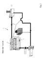
- FIGS. 1 and 2 A conventional cooling system 1 is shown in FIGS. 1 and 2.
- the conventional cooling system 1 has both a cylinder head water jacket 2 and an engine block water jacket 3, a pump 4, a radiator 6 (FIG. 2), a thermostat 7, and a heater 8. Furthermore, the coolant circuit 1 can have degassing devices 9 and of course connecting lines 11 to the individual components.
- the coolant flows through the pump 4, through the two water jackets 2, 3, the heater 8 and the thermostat 7, wherein the respective components are connected in series with each other.
- a specific cooling temperature for example 90 ° C
- the coolant flows through the pump 4, through the two water jackets 2, 3, the heater 8 and the thermostat 7, wherein the respective components are connected in series with each other.
- FIG. 1 shows by way of example in FIG. 1 as an illustration of the known state of the art.
- the thermostat 7 opens, so that the coolant additionally flows through the radiator 6 in parallel with the heater 8.
- the specific temperature for opening the thermostat is set to 90 ° C or predetermined, this temperature is of course not limited to said amount, but of course may have other amounts.
- the invention has for its object to improve a separate coolant circuit of the type mentioned by simple means so that the warm-up phase of the engine block is significantly reduced.
- the object is achieved in that the thermostat is arranged such that it controls a flow of the coolant through the engine block water jacket and through the radiator simultaneously when the coolant exceeds a predetermined temperature.
- the individual components of the separate coolant circuit in, in comparison to the prior art, of different types connected to each other, so that the heat output from the engine block during its warm-up phase is significantly reduced.
- the advantageous embodiment of the coolant circuit according to the invention combines the advantages of the separate coolant circuit (rapid warm-up), whereby the fuel consumption and the generation of harmful emissions are significantly reduced, but also the life of the internal combustion engine is extended or increased.
- the same components can be used as in the conventional coolant circuit.
- the thermostat is arranged in the flow direction of the coolant between the engine and the heater.
- the thermostat is connected via a connecting line to the engine block water jacket, wherein the engine block water jacket is conveniently connected to the radiator.
- the heater is connected to the pump, it is expediently provided that the radiator is connected to a connecting line of the heater to the pump.
- thermostat simultaneously controls the flow of coolant through both the radiator and the engine block water jacket, the thermostat can be advantageously designed as a single-acting thermostat.
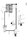
- FIGs 3 and 4 show a separate refrigerant circuit 16 ("split-cooling system") of an internal combustion engine 17, wherein a cylinder head water jacket 18 and an engine block water jacket 19 ( Figure 4) is provided.
- the separate coolant circuit 16 has a pump 21, a radiator 22, a thermostat 23 and a heater 24, wherein in the separate coolant circuit 16, a coolant circulates.
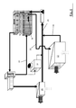
- the thermostat 23 is arranged to simultaneously control a flow of the coolant through the engine block water jacket 19 and through the radiator 22 when the coolant exceeds a predetermined temperature (FIG. 4).
- the predetermined temperature should be 90 ° C in the illustrated embodiments, so that the thermostat is closed below a coolant temperature of 90 ° C ( Figure 3) and above a coolant temperature of 90 ° C is open ( Figure 4).
- the indicated coolant temperature is given by way of example only, and is not intended to be limiting.
- the thermostat 23 is disposed between the engine 17 and the heater 24.
- the heater 24 is connected via a connecting line 26 to the pump 21, which is connected via a connecting line 27 to the engine 17.
- the coolant flows from the pump 21 directly into the cylinder head water jacket 18 and is supplied from there via a connecting line 28 to the thermostat 23.
- the thermostat 23 is designed as a single-acting thermostat so that it is closed at a coolant temperature below the exemplified 90 ° C, which means that the coolant is fed through the thermostat 23 directly to the heater 24, which of course also a connecting line 29th is provided. It is easily conceivable that a warm-up phase of the internal combustion engine 17 can be significantly reduced by this arrangement, since the engine block is not initially cooled.
- FIGS. 3 and 4 furthermore show a degassing device 31.
- the thermostat 23 opens to a connection line 32 which is connected to the engine block water jacket 19 ( Figure 4).
- the coolant flows, as can be seen in FIG. 4, through the thermostat 23 both to the heater 24 and to the engine block water jacket 19. From the engine block water jacket 19, the coolant flows via a connecting line 33 to the radiator 22, the coolant here being similar in the heater 24 is cooled.
- the radiator 22 is connected via a connecting line 34 with the connecting line 26 of the heater 24 to the pump 21, wherein the connecting line 34 opens into the connecting line 26.
- the warm-up of the engine is significantly shortened, this effect using known components surprisingly achieved by a different arrangement of the components, in particular the thermostat 23, which is advantageously designed as a low-cost, single-acting thermostat becomes.
Abstract
Description
- Die Erfindung betrifft einen getrennten Kühlmittelkreislauf eines Verbrennungsmotors, wobei ein Zylinderkopfwassermantel und ein Motorblockwassermantel vorgesehen ist, wobei der getrennte Kühlmittelkreislauf eine Pumpe, einen Kühler, ein Thermostat und eine Heizung aufweist, und wobei in dem getrennten Kühlmittelkreislauf ein Kühlmittel zirkuliert.
- Bekannt ist, daß es zweckmäßig ist, den Motorblock und den Zylinderkopf des Verbrennungsmotors jeweils getrennt oder wenigstens überwiegend getrennt voneinander mit einem Kühlmittel eines Kühlmittelkreislaufs durchströmen zu lassen. Auf diese Weise können der Zylinderkopf, der thermisch vor allem mit der Brennraumwand, der Ansaugluftführung und der Abgasabführung gekoppelt ist und der Motorblock, der thermisch vor allem mit den Reibstellen gekoppelt ist, unterschiedlich gekühlt werden. Durch dieses so genannte "Split-Cooling-System" (getrennter Kühlmittelkreislauf) soll erreicht werden, daß in der Warmlaufphase des Verbrennungsmotors der Zylinderkopf gekühlt wird, wobei der Motorblock zunächst noch nicht gekühlt werden soll, so daß der Motorblock schneller auf die erforderliche Betriebstemperatur geführt werden kann, d. h. unter getrenntem Kühlkreislauf sind nicht zwei Kühlkreisläufe zu verstehen, sondern es ist ein Kühlkreislauf für eine Brennkraftmaschine gemeint, bei der der Wassermantel des Zylinderkopfes von dem Wassermantel des Zylinderblocks durch geeignete Mittel separiert ist. Bei manchen Konstruktionsformen können allerdings auch kleine Leckagen vom Zylinderkopfwassermantel zum Zylinderblockwassermantel vorgesehen sein, wobei die Leckagemengen so gering sind, daß man trotzdem von einem getrennten Kühlkreislauf sprechen kann.
- In der
DE 103 42 935 A1 z. B. ist eine Verbrennungskraftmaschine mit einem Kühlkreislauf mit wenigstens einem ersten Kühlmittelkanal und wenigstens einem zweiten Kühlmittelkanal offenbart, der parallel mit dem ersten Kühlmittelkanal verbunden ist. Weiter weist die Verbrennungskraftmaschine den Kühlmittelkanälen zugeordnete Drosselungsmittel für die Beeinflussung des die Kühlmittelkanäle passierenden Kühlmittelstroms auf, sowie eine mechanisch antreibbare Kühlmittelpumpe für die Umwälzung des Kühlmittels durch die Kühlmittelkanäle. Es sind Steuermittel vorgesehen, die Stellgrößen für die individuelle Steuerung der Drosselungsmittel bereitstellen. - Die
DE 195 24 424 A1 betrifft eine Flüssigkeitskühlung einer Brennkraftmaschine mit einem Kühlflüssigkeitsstrom durch einen Kühlflüssigkeitskreislauf, in dem ein von der Kühlflüssigkeit durchströmter Kühlraum der Brennkraftmaschine, ein Kühler für die Kühlflüssigkeit, eine die Kühlflüssigkeit umwälzende Pumpe und ein thermostatisch kontrolliertes Ventil vorgesehen ist, das bei einer niedrigen Kühlflüssigkeitstemperatur den Kühlflüssigkeitsstrom durch den Kühlraum der Brennkraftmaschine bei einer niedrigen Kühlflüssigkeitstemperatur den Kühlflüssigkeitsstrom durch den Kühler unterhalb des Wertes des Kühlflüssigkeitsstroms durch den Kühlraum der Brennkraftmaschine reduziert. Es kann aber auch ein Lastsensor der Brennkraftmaschine vorgesehen sein, der bei einer hohen Last der Brennkraftmaschine der Reduzierung des Kühlflüssigkeitsstroms durch den Kühlraum der Brennkraftmaschine entgegenwirkt. Zudem können ein mit dem Kühlflüssigkeitskreislauf verbundener Heizungswärmetauscher und ein Stellmittel vorgesehen sein, das bei einer in Betriebnahme und/oder Steigerung einer Betriebsamkeit des Heizungswärmetauschers der Reduzierung des Kühlflüssigkeitsstromes durch den Kühler entgegenwirkt. - Die
DE 102 61 070 A1 offenbart eine Wasserummantelungsstruktur für einen Zylinderkopf und einen Zylinderblock eines Motors mit einem darin angepaßten, geteilten Kühlsystem. Die Wasserummantelungen für den Zylinderkopf und den Zylinderblock sind jeweilig und unabhängig voneinander geformt, wobei ein Einlaß zwischen dem Zylinderkopf und dem Zylinderblock geteilt ist. Dessen Querschnittsfläche ist nach innen gelangend reduziert, wobei Positionen von zwei Auslässen zu dem Zylinderkopf verschoben sind. - Auch in der
KR 1020040033579 A DE 101 27 219 A1 ist eine Kühlanlage für einen Verbrennungsmotor mit wenigstens zwei Zylinderreihen, insbesondere für einen V-Motor offenbart. - Die
DE 102 19 481 A1 beschäftigt sich mit einem Verbrennungsmotor mit einem Zylinderkurbelgehäuse und einem Zylinderkopf, mit einem Kühlwasserkreislauf mit einem im Zylinderkopf zwischen einer Zutrittsöffnung und einer Austrittsöffnung erstreckend ausgebildeten ersten Kühlwassermantel und mit einem hiervon getrennt in Zylinderkurbelgehäuse zwischen einer Zutrittsöffnung und einer Austrittsöffnung erstreckend ausgebildeten zweiten Kühlwasserkanal und mit einer im Kühlwasserkreislauf angeordneten, gemeinsamen Kühlwasserpumpe. Ein dritter Kühlwasserkanal verbindet die Austrittsöffnung des ersten im Zylinderkopf ausgebildeten Kühlwasserkanals mit der Zutrittsöffnung der Kühlwasserpumpe. Ein vierter Kühlwasserkanal verbindet die Austrittsöffnung der Kühlwasserpumpe mit der Zutrittsöffnung des zweiten im Zylinderkurbelgehäuse ausgebildeten Kühlwasserkanals zur Weiterleitung des Kühlwassers aus dem ersten in den zweiten Kühlwasserkanal. - Auch die
DE 196 28 542 A1 beschäftigt sich mit einem Split-Cooling-System, wobei der Zylinderkopf bzw. die Zylinderköpfe durch einen Kühlwasserkreislauf gekühlt sind, der nur durch den Zylinderkopf verläuft und in dem eine Kühlwasserpumpe eingefügt ist. - Ebenso beschäftigt sich die
DE 34 40 504 C2 mit dem Split-Cooling-System bzw. getrennten Kühlmittelkreisläufen für einen Zylinderblock und den Motorblock. - Die
EP 0 816 651 B1 beschäftigt sich mit dem Problem, eine Vorrichtung anzugeben, welche die Aufheizzeit einer Auspuffleitung verringern und gleichzeitig die Temperatur der Wände des Motorblocks bei geringer Last auf einen ausreichenden Wert schnell ansteigen lassen und halten kann, wobei jedenfalls die Betriebsbedingungen des Motors in allen Betriebszuständen verbessert werden sollen. Zu diesem Zweck offenbart dieEP 0 816 651 B1 eine Vorrichtung für den Verbrennungsmotor, welcher einen Zylinderblock und einen Zylinderkopf aufweist, deren Wände zum Begrenzen eines ersten Teils und eines zweiten, davon unterschiedlichen Teils, und desselben durch diese Wände getrennten Kühlkreislauf gestaltet sind. - Die
EP 1 239 129 A2 beschäftigt sich mit einem einfachen Kühlsystem zur Kühlung des Verbrennungsmotors. - Ein herkömmliches Kühlsystem 1 ist in den Figuren 1 und 2 dargestellt. Das herkömmliche Kühlsystem 1 weist sowohl einen Zylinderkopfwassermantel 2 und einen Motorblockwassermantel 3, eine Pumpe 4, einen Kühler 6 (Figur 2), ein Thermostat 7 und eine Heizung 8 auf. Weiter kann der Kühlmittelkreislauf 1 Entgasungsvorrichtungen 9 und natürlich Verbindungsleitungen 11 zu den einzelnen Bestandteilen aufweisen.
- Unterhalb einer spezifischen Kühltemperatur von beispielsweise 90°C fließt das Kühlmittel durch die Pumpe 4, durch die beiden Wassermäntel 2, 3, die Heizung 8 und das Thermostat 7, wobei die jeweiligen Bestandteile in Serie zueinander geschaltet sind. Dies ist beispielhaft in Figur 1 als Darstellung des bekannten Standes der Technik dargestellt.
- Wenn das Steuerelement dem Thermostat 7 das Erreichen der spezifischen Temperatur anzeigt, öffnet das Thermostat 7, so daß das Kühlmittel zusätzlich durch den Kühler 6 parallel zu der Heizung 8 fließt. Dies ist beispielhaft in Figur 2 zum Stand der Technik dargestellt. In dem in den Figur 1 und 2 dargestellten Ausführungsbeispiel ist die spezifische Temperatur zum Öffnen des Thermostats auf 90°C festgelegt bzw. vorgegeben, wobei diese Temperatur natürlich nicht auf den genannten Betrag beschränkt sein soll, sondern natürlich auch andere Beträge aufweisen kann.
- Im Stand der Technik sind die Vorteile und Ausgestaltungskonzepte von getrennten Kühlkreisläufen (Split-Cooling-System) im Vergleich zu dem in den Figuren 1 und 2 dargestellten konventionellen Kühlmittelkreislauf seit langer Zeit bekannt, wobei aber die Realisation, insbesondere wegen der entstehenden Kosten eines zusätzlichen Thermostats oder eines komplexen zweifach wirkenden Thermostats äußerst schwierig ist. Nachteilig ist weiterhin, daß die Kühlmittelströmungsaufteilung zwischen dem Zylinderkopf und dem Motorblockwassermantel in beiden Phasen (Thermostat geschlossen unterhalb 90°C, Thermostat geöffnet oberhalb 90°C) fixiert ist, was zu einer unnötigen hohen Wärmeabgabe und einer geringen Aufwärmung des Motorblocks und des Ölfilms entlang der Laufbuchsen führt.
- Von daher liegt der Erfindung die Aufgabe zugrunde, einen getrennten Kühlmittelkreislauf der eingangs genannten Art mit einfachen Mitteln so zu verbessern, daß die Aufwärmphase des Motorblocks erheblich reduziert ist.
- Erfindungsgemäß wird die Aufgabe dadurch gelöst, daß das Thermostat derart angeordnet ist, daß dieses eine Strömung des Kühlmittels durch den Motorblockwassermantel und durch den Kühler simultan steuert, wenn das Kühlmittel eine vorgegebene Temperatur übersteigt.
- Vorteilhaft sind die einzelnen Komponenten des getrennten Kühlmittelkreislaufes in, im Vergleich zum Stand der Technik, unterschiedlicher Art miteinander verbunden, so daß die Wärmeabgabe von dem Motorblock während seiner Aufwärmphase erheblich reduziert ist. Dies führt zu höheren Werkstoff- als auch Öltemperaturen, wodurch die Reibung und die thermischen Verluste reduziert werden. Die vorteilhafte Ausführung des erfindungsgemäßen Kühlmittelkreislaufs kombiniert die Vorteile des getrennten Kühlmittelkreislaufs (schnelles Aufwärmen), wodurch der Kraftstoffverbrauch und die Entstehung schädlicher Emissionen erheblich verringert werden, wodurch aber auch die Lebensdauer des Verbrennungsmotors verlängert bzw. erhöht wird.
- Vorteilhaft können aber die gleichen Komponenten verwendet werden, wie in dem konventionellen Kühlmittelkreislauf. Günstig im Sinne der Erfindung ist vorgesehen, daß das Thermostat in Fließrichtung des Kühlmittels gesehen zwischen dem Verbrennungsmotor und der Heizung angeordnet ist.
- Zweckmäßigerweise ist das Thermostat über eine Verbindungsleitung mit dem Motorblockwassermantel verbunden, wobei der Motorblockwassermantel günstigerweise mit dem Kühler verbunden ist.
- Vorteilhaft ist die Heizung mit der Pumpe verbunden, wobei zweckmäßigerweise vorgesehen ist, daß der Kühler mit einer Verbindungsleitung der Heizung zur Pumpe verbunden ist.
- Durch die erfindungsgemäße Ausgestaltung des getrennten Kühlmittelkreislaufes, bei dem das Thermostat den Kühlmittelfluß sowohl durch den Kühler als auch durch den Motorblockwassermantel simultan steuert, kann das Thermostat vorteilhaft als einfach wirkendes Thermostat ausgeführt sein.
- Weitere vorteilhafte Ausgestaltungen der Erfindung sind in den Unteransprüchen und der folgenden Figurenbeschreibung offenbart. Es zeigen:
- Fig. 1und Fig. 2
- Ausführungen von Kühlmittelkreisläufen nach dem Stande der Technik
- Fig. 3
- eine Prinzipskizze eines getrennten Kühlmittelkreislaufes mit einem geschlossenen Thermostat, und
- Fig. 4
- den Kühlmittelkreislauf aus Figur 3 mit geöffnetem Thermostat.
- In den unterschiedlichen Figuren sind gleiche Teile stets mit denselben Bezugszeichen versehen, so daß diese in der Regel auch nur einmal beschrieben werden.
- Figur 1 und 2 wurden bereits bei der Würdigung des Standes der Technik behandelt.
- Die Figuren 3 und 4 zeigen einen getrennten Kühlmittelkreislauf 16 ("Split-cooling-System") eines Verbrennungsmotors 17, wobei ein Zylinderkopfwassermantel 18 und ein Motorblockwassermantel 19 (Figur 4) vorgesehen ist. Der getrennte Kühlmittelkreislauf 16 weist eine Pumpe 21, einen Kühler 22, ein Thermostat 23 und eine Heizung 24 auf, wobei in dem getrennten Kühlmittelkreislauf 16 ein Kühlmittel zirkuliert. Das Thermostat 23 ist derart angeordnet, daß dieses eine Strömung des Kühlmittels durch den Motorblockwassermantel 19 und durch den Kühler 22 simultan steuert, wenn das Kühlmittel eine vorgegebene Temperatur übersteigt (Figur 4).
- Die vorgegebene Temperatur soll in den dargestellten Ausführungsbeispielen 90°C betragen, so daß das Thermostat unterhalb einer Kühlmitteltemperatur von 90°C geschlossen ist (Figur 3) und oberhalb einer Kühlmitteltemperatur von 90°C geöffnet ist (Figur 4). Selbstverständlich ist die angegebene Kühlmitteltemperatur nur beispielhaft genannt, und soll nicht beschränkend sein.
- Das Thermostat 23 ist zwischen dem Verbrennungsmotor 17 und der Heizung 24 angeordnet. Die Heizung 24 ist über eine Verbindungsleitung 26 mit der Pumpe 21 verbunden, welche über eine Verbindungsleitung 27 mit dem Verbrennungsmotor 17 verbunden ist. Wie der Figur 3 zu entnehmen ist, fließt das Kühlmittel von der Pumpe 21 ausgehend direkt in den Zylinderkopfwassermantel 18 und wird von dort aus über eine Verbindungsleitung 28 dem Thermostat 23 zugeführt.
- Das Thermostat 23 ist als einfach wirkendes Thermostat ausgeführt, so daß dieses bei einer Kühlmitteltemperatur unterhalb der beispielhaft genannten 90°C geschlossen ist, was bedeutet, daß das Kühlmittel durch das Thermostat 23 direkt der Heizung 24 zugeleitet wird, wobei hier natürlich ebenfalls eine Verbindungsleitung 29 vorgesehen ist. Es ist leicht vorstellbar, daß durch diese Anordnung eine Aufwärmphase des Verbrennungsmotors 17 erheblich reduziert werden kann, da der Motorblock zunächst nicht gekühlt wird.
- Den Figuren 3 und 4 ist weiterhin eine Entgasungsvorrichtung 31 zu entnehmen.
- Wenn die Kühlmitteltemperatur die vorgegebene Temperatur von beispielsweise 90°C übersteigt, öffnet das Thermostat 23 zu einer Verbindungsleitung 32, welche mit dem Motorblockwassermantel 19 verbunden ist (Figur 4). Das Kühlmittel fließt, wie der Figur 4 zu entnehmen ist, durch das Thermostat 23 also sowohl zu der Heizung 24 als auch zu dem Motorblockwassermantel 19. Aus dem Motorblockwassermantel 19 strömt das Kühlmittel über eine Verbindungsleitung 33 zum Kühler 22, wobei das Kühlmittel hier ähnlich wie in der Heizung 24 gekühlt wird. Der Kühler 22 ist über eine Verbindungsleitung 34 mit der Verbindungsleitung 26 der Heizung 24 zur Pumpe 21 verbunden, wobei die Verbindungsleitung 34 in die Verbindungsleitung 26 mündet.
- Weiter ist der Figur 4 zu entnehmen, daß die Entgasungsvorrichtung 31 mit der Verbindungsleitung 32 des Thermostats 23 zum Motorblockwassermantel 19 und zum anderen mit der Verbindungsleitung 26 der Heizung 24 zur Pumpe 21 verbunden ist.
- Bei dem in den Figuren 3 und 4 dargestellten Ausführungsbeispiel wird die Aufwärmphase des Verbrennungsmotors erheblich verkürzt, wobei dieser Effekt unter Verwendung bekannter Komponenten überraschenderweise durch eine andere Anordnung der Komponenten, insbesondere des Thermostats 23, welches vorteilhaft als preiswertes, einfach wirkendes Thermostat ausgeführt ist, erreicht wird.
Claims (7)
- Getrennter Kühlmittelkreislauf eines Verbrennungsmotors (17), wobei ein Zylinderkopfwassermantel (18) und ein Motorblockwassermantel (19) vorgesehen ist, wobei der getrennte Kühlmittelkreislauf (16) eine Pumpe (21), einen Kühler (22), ein Thermostat (23) und eine Heizung (24) aufweist, und wobei in dem getrennten Kühlmittelkreislauf (16) ein Kühlmittel zirkuliert,
dadurch gekennzeichnet, daß
das Thermostat (23) derart angeordnet ist, daß dieses eine Strömung des Kühlmittels durch den Motorblockwassermantel (19) und durch den Kühler (22) simultan steuert, wenn das Kühlmittel eine vorgegebene Temperatur übersteigt. - Getrennter Kühlmittelkreislauf nach Anspruch 1,
dadurch gekennzeichnet, daß
das Thermostat (23) in Fließrichtung des Kühlmittels gesehen zwischen dem Verbrennungsmotor (17) und der Heizung (24) angeordnet ist. - Getrennter Kühlmittelkreislauf nach Anspruch 1 oder 2,
dadurch gekennzeichnet, daß
das Thermostat (23) über eine Verbindungsleitung (32) mit dem Motorblockwassermantel (19) verbunden ist. - Getrennter Kühlmittelkreislauf nach einem der vorhergehenden Ansprüche,
dadurch gekennzeichnet, daß
der Motorblockwassermantel (19) mit dem Kühler (22) verbunden ist. - Getrennter Kühlmittelkreislauf nach einem der vorhergehenden Ansprüche,
dadurch gekennzeichnet, daß
die Heizung (24) mit der Pumpe (21) verbunden ist. - Getrennter Kühlmittelkreislauf nach einem der vorhergehenden Ansprüche,
dadurch gekennzeichnet, daß
der Kühler (22) mit einer Verbindungsleitung (26) der Heizung (24) zur Pumpe (21) verbunden ist. - Getrennter Kühlmittelkreislauf nach einem der vorhergehenden Ansprüche,
dadurch gekennzeichnet, daß
das Thermostat (23) als einfach wirkendes Thermostat ausgeführt ist.
Priority Applications (3)
| Application Number | Priority Date | Filing Date | Title |
|---|---|---|---|
| DE502006009008T DE502006009008D1 (de) | 2006-09-13 | 2006-09-13 | Kühlmittelkreislauf |
| EP06120586A EP1900919B1 (de) | 2006-09-13 | 2006-09-13 | Kühlmittelkreislauf |
| US11/853,067 US20080060592A1 (en) | 2006-09-13 | 2007-09-11 | Split Cooling System for an Internal Combustion Engine |
Applications Claiming Priority (1)
| Application Number | Priority Date | Filing Date | Title |
|---|---|---|---|
| EP06120586A EP1900919B1 (de) | 2006-09-13 | 2006-09-13 | Kühlmittelkreislauf |
Publications (2)
| Publication Number | Publication Date |
|---|---|
| EP1900919A1 true EP1900919A1 (de) | 2008-03-19 |
| EP1900919B1 EP1900919B1 (de) | 2011-03-02 |
Family
ID=37110349
Family Applications (1)
| Application Number | Title | Priority Date | Filing Date |
|---|---|---|---|
| EP06120586A Active EP1900919B1 (de) | 2006-09-13 | 2006-09-13 | Kühlmittelkreislauf |
Country Status (3)
| Country | Link |
|---|---|
| US (1) | US20080060592A1 (de) |
| EP (1) | EP1900919B1 (de) |
| DE (1) | DE502006009008D1 (de) |
Cited By (5)
| Publication number | Priority date | Publication date | Assignee | Title |
|---|---|---|---|---|
| CN101813020A (zh) * | 2009-02-25 | 2010-08-25 | 福特环球技术公司 | 冷却方法 |
| DE102010002082A1 (de) | 2010-02-18 | 2011-08-18 | Ford Global Technologies, LLC, Mich. | Separat gekühlter Abgassammler zur Aufrechterhaltung einer No-Flow Strategie des Zylinderblockkühlmittelmantels |
| EP2392794A1 (de) | 2010-06-07 | 2011-12-07 | Ford Global Technologies, LLC | Separat gekühlter Turbolader zur Aufrechterhaltung einer No-Flow Strategie eines Zylinderblockkühlmittelmantels |
| DE102009054814B4 (de) * | 2009-12-17 | 2013-11-28 | Ford Global Technologies, Llc | Verfahren zur Optimierung eines Thermomanagements in einem Kraftfahrzeug |
| DE102018218871A1 (de) | 2018-11-06 | 2020-05-07 | Ford Global Technologies, Llc | Anordnung und Verfahren zur Verringerung der Kondensatbildung in einem Zuluftstrang eines Verbrennungsmotors sowie Kraftfahrzeug |
Families Citing this family (13)
| Publication number | Priority date | Publication date | Assignee | Title |
|---|---|---|---|---|
| US9849753B2 (en) * | 2008-05-16 | 2017-12-26 | GM Global Technology Operations LLC | Heating system for an automotive vehicle |
| US8739745B2 (en) | 2011-08-23 | 2014-06-03 | Ford Global Technologies, Llc | Cooling system and method |
| EP2562378B1 (de) | 2011-08-23 | 2015-10-14 | Ford Global Technologies, LLC | Strategie zum Betreiben eines getrennten Kühlmittelkreislaufs |
| EP2562379B1 (de) | 2011-08-23 | 2015-10-14 | Ford Global Technologies, LLC | Kühlmittelkreislauf |
| US8991339B2 (en) | 2012-03-30 | 2015-03-31 | Ford Global Technologies, Llc | Multi-zone vehicle radiators |
| AT513175B1 (de) * | 2012-07-26 | 2014-10-15 | Avl List Gmbh | Flüssigkühlsystem für eine Brennkraftmaschine eines Fahrzeuges |
| DE102014004009A1 (de) | 2014-03-20 | 2015-12-03 | Daimler Ag | Kühlmittelkreislauf zum Kühlen einer Verbrennungskraftmaschine, insbesondere für einen Kraftwagen, sowie Verfahren zum Betreiben eines solchen Kühlmittelkreislaufs |
| US9758171B2 (en) * | 2015-06-15 | 2017-09-12 | GM Global Technology Operations LLC | Method and apparatus for controlling a multi-mode powertrain system including an engine having stop/start capability |
| CN105673179B (zh) * | 2016-03-22 | 2018-04-20 | 浙江大学 | 一种基于分体冷却及反向冷却的发动机智能冷却系统试验台及试验方法 |
| JP6897347B2 (ja) * | 2017-06-08 | 2021-06-30 | スズキ株式会社 | エンジンの冷却用オイル通路構造 |
| US10538214B2 (en) * | 2017-11-15 | 2020-01-21 | Denso International America, Inc. | Controlled in-tank flow guide for heat exchanger |
| CN108049956B (zh) * | 2017-12-08 | 2024-01-23 | 重庆小康工业集团股份有限公司 | 发动机冷却系统 |
| CN112065565B (zh) * | 2020-09-15 | 2021-11-30 | 奇瑞汽车股份有限公司 | 节温器总成、冷却系统、发动机和汽车 |
Citations (5)
| Publication number | Priority date | Publication date | Assignee | Title |
|---|---|---|---|---|
| DE8702564U1 (de) * | 1986-02-20 | 1987-06-25 | Fiat Auto S.P.A., Turin/Torino, It | |
| US5385123A (en) * | 1993-10-08 | 1995-01-31 | Evans; John W. | Segregated cooling chambers for aqueous reverse-flow engine cooling systems |
| EP0816651A1 (de) * | 1996-06-24 | 1998-01-07 | Automobiles Peugeot | Kühlungsvorrichtung einer Brennkraftmaschine |
| WO2003093661A1 (de) * | 2002-04-30 | 2003-11-13 | Audi Ag | Einrichtung und verfahren zur kühlung einer brennkraftmaschine |
| FR2860833A1 (fr) * | 2003-10-08 | 2005-04-15 | Peugeot Citroen Automobiles Sa | Circuit de refroidissement d'un moteur a combustion interne constitue d'au moins trois passages de refroidissement |
Family Cites Families (3)
| Publication number | Priority date | Publication date | Assignee | Title |
|---|---|---|---|---|
| US5337704A (en) * | 1993-09-29 | 1994-08-16 | Chrysler Corporation | Engine cooling system with thermostat coolant flow control between head and block |
| JP3185581B2 (ja) * | 1995-02-09 | 2001-07-11 | トヨタ自動車株式会社 | 内燃機関の冷却装置 |
| JP2003120291A (ja) * | 2001-10-10 | 2003-04-23 | Honda Motor Co Ltd | エンジンの冷却構造 |
-
2006
- 2006-09-13 DE DE502006009008T patent/DE502006009008D1/de active Active
- 2006-09-13 EP EP06120586A patent/EP1900919B1/de active Active
-
2007
- 2007-09-11 US US11/853,067 patent/US20080060592A1/en not_active Abandoned
Patent Citations (5)
| Publication number | Priority date | Publication date | Assignee | Title |
|---|---|---|---|---|
| DE8702564U1 (de) * | 1986-02-20 | 1987-06-25 | Fiat Auto S.P.A., Turin/Torino, It | |
| US5385123A (en) * | 1993-10-08 | 1995-01-31 | Evans; John W. | Segregated cooling chambers for aqueous reverse-flow engine cooling systems |
| EP0816651A1 (de) * | 1996-06-24 | 1998-01-07 | Automobiles Peugeot | Kühlungsvorrichtung einer Brennkraftmaschine |
| WO2003093661A1 (de) * | 2002-04-30 | 2003-11-13 | Audi Ag | Einrichtung und verfahren zur kühlung einer brennkraftmaschine |
| FR2860833A1 (fr) * | 2003-10-08 | 2005-04-15 | Peugeot Citroen Automobiles Sa | Circuit de refroidissement d'un moteur a combustion interne constitue d'au moins trois passages de refroidissement |
Cited By (12)
| Publication number | Priority date | Publication date | Assignee | Title |
|---|---|---|---|---|
| CN101813020A (zh) * | 2009-02-25 | 2010-08-25 | 福特环球技术公司 | 冷却方法 |
| DE102009001129B4 (de) * | 2009-02-25 | 2014-07-10 | Ford Global Technologies, Llc | Kühlstrategie für Verbrennungsmotoren |
| CN101813020B (zh) * | 2009-02-25 | 2015-08-12 | 福特环球技术公司 | 冷却方法 |
| DE102009054814B4 (de) * | 2009-12-17 | 2013-11-28 | Ford Global Technologies, Llc | Verfahren zur Optimierung eines Thermomanagements in einem Kraftfahrzeug |
| DE102010002082A1 (de) | 2010-02-18 | 2011-08-18 | Ford Global Technologies, LLC, Mich. | Separat gekühlter Abgassammler zur Aufrechterhaltung einer No-Flow Strategie des Zylinderblockkühlmittelmantels |
| CN102162391A (zh) * | 2010-02-18 | 2011-08-24 | 福特环球技术公司 | 用于保持汽缸体冷却套的无流策略的独立冷却排气收集器 |
| DE102010002082B4 (de) * | 2010-02-18 | 2013-09-19 | Ford Global Technologies, Llc | Separat gekühlter Abgassammler zur Aufrechterhaltung einer No-Flow Strategie des Zylinderblockkühlmittelmantels |
| US9212620B2 (en) | 2010-02-18 | 2015-12-15 | Ford Global Technologies, Llc | Coolant jackets for an internal combustion engine and method of control |
| CN102162391B (zh) * | 2010-02-18 | 2016-06-01 | 福特环球技术公司 | 一种内燃发动机的冷却装置及其冷却剂控制方法 |
| EP2392794A1 (de) | 2010-06-07 | 2011-12-07 | Ford Global Technologies, LLC | Separat gekühlter Turbolader zur Aufrechterhaltung einer No-Flow Strategie eines Zylinderblockkühlmittelmantels |
| US8833073B2 (en) | 2010-06-07 | 2014-09-16 | Ford Global Technologies, Llc | Separately cooled turbocharger for maintaining a no-flow strategy of an engine block coolant jacket |
| DE102018218871A1 (de) | 2018-11-06 | 2020-05-07 | Ford Global Technologies, Llc | Anordnung und Verfahren zur Verringerung der Kondensatbildung in einem Zuluftstrang eines Verbrennungsmotors sowie Kraftfahrzeug |
Also Published As
| Publication number | Publication date |
|---|---|
| EP1900919B1 (de) | 2011-03-02 |
| US20080060592A1 (en) | 2008-03-13 |
| DE502006009008D1 (de) | 2011-04-14 |
Similar Documents
| Publication | Publication Date | Title |
|---|---|---|
| EP1900919B1 (de) | Kühlmittelkreislauf | |
| EP1947308B1 (de) | Integriertes Motorkühlsystem | |
| DE102010002082B4 (de) | Separat gekühlter Abgassammler zur Aufrechterhaltung einer No-Flow Strategie des Zylinderblockkühlmittelmantels | |
| EP2392794B1 (de) | Separat gekühlter Turbolader zur Aufrechterhaltung einer No-Flow Strategie eines Zylinderblockkühlmittelmantels | |
| DE102012200005B4 (de) | Verfahren zum Betreiben eines Kühlmittelkreislaufs | |
| DE102010010594B4 (de) | Kühlkreislauf für eine Brennkraftmaschine | |
| DE102008035955B4 (de) | Kühlstrategie | |
| EP2562379B1 (de) | Kühlmittelkreislauf | |
| DE102014201717A1 (de) | Brennkraftmaschine mit flüssigkeitsgekühltem Zylinderkopf und Zylinderblock und Verfahren zur Steuerung der Kühlung einer derartigen Brennkraftmaschine | |
| DE112014000928T5 (de) | Kühlvorrichtung für Mehrzylindermotor | |
| DE102013214838A1 (de) | Brennkraftmaschine mit flüssigkeitsgekühltem Zylinderkopf und flüssigkeitsgekühltem Zylinderblock und Verfahren zum Betreiben einer derartigen Brennkraftmaschine | |
| EP2077388B1 (de) | Kombination mit Zylinderkopf und Zylinderblock und Verwendung einer derartigen Kombination | |
| EP2143926A1 (de) | Kombination mit Zylinderkopf und Turbine | |
| DE102015201238B3 (de) | Verfahren zum Betrieb einer Brennkraftmaschine mit Split-Kühlsystem und Zylinderabschaltung | |
| DE112015000115B4 (de) | Abgasrückführungsventil, System zum Auftauen von Abgasrückführungsventil und Motor | |
| DE102008042660A1 (de) | Flüssigkeitsgekühlte Brennkraftmaschine mit Ölkühler und Verfahren zum Betreiben einer derartigen Brennkraftmaschine | |
| DE102010001752B4 (de) | Kühlsystem | |
| DE102015201240B4 (de) | Split-Kühlsystem sowie Brennkraftmaschine mit einem Split-Kühlsystem und entsprechend ausgestattetes Fahrzeug | |
| EP2562378B1 (de) | Strategie zum Betreiben eines getrennten Kühlmittelkreislaufs | |
| DE102015201242B4 (de) | Regelmittel zur Steuerung der Kühlmittelströme eines Split-Kühlsystems | |
| EP3320197A1 (de) | Kühlmittelkreislauf für flüssigkeitsgekühlte getriebe | |
| EP2241734A1 (de) | Zylinderkopf mit Turbinen und Verfahren zum Betreiben einer Brennkraftmaschine mit einem derartigen Zylinderkopf | |
| WO2017012875A1 (de) | Brennkraftmaschine mit geteiltem kühlsystem | |
| DE102006048527B4 (de) | Kühlkreislauf für eine Brennkraftmaschine | |
| DE102010036581A1 (de) | Flüssigkeitsgekühlte Brennkraftmaschine mit kühlmittelbetriebener Heizung und Verfahren zum Betreiben einer derartigen Brennkraftmaschine |
Legal Events
| Date | Code | Title | Description |
|---|---|---|---|
| PUAI | Public reference made under article 153(3) epc to a published international application that has entered the european phase |
Free format text: ORIGINAL CODE: 0009012 |
|
| AK | Designated contracting states |
Kind code of ref document: A1 Designated state(s): AT BE BG CH CY CZ DE DK EE ES FI FR GB GR HU IE IS IT LI LT LU LV MC NL PL PT RO SE SI SK TR |
|
| AX | Request for extension of the european patent |
Extension state: AL BA HR MK YU |
|
| 17P | Request for examination filed |
Effective date: 20080919 |
|
| AKX | Designation fees paid |
Designated state(s): DE FR GB |
|
| 17Q | First examination report despatched |
Effective date: 20100319 |
|
| GRAP | Despatch of communication of intention to grant a patent |
Free format text: ORIGINAL CODE: EPIDOSNIGR1 |
|
| GRAS | Grant fee paid |
Free format text: ORIGINAL CODE: EPIDOSNIGR3 |
|
| GRAA | (expected) grant |
Free format text: ORIGINAL CODE: 0009210 |
|
| AK | Designated contracting states |
Kind code of ref document: B1 Designated state(s): DE FR GB |
|
| REG | Reference to a national code |
Ref country code: GB Ref legal event code: FG4D Free format text: NOT ENGLISH |
|
| REF | Corresponds to: |
Ref document number: 502006009008 Country of ref document: DE Date of ref document: 20110414 Kind code of ref document: P |
|
| REG | Reference to a national code |
Ref country code: DE Ref legal event code: R096 Ref document number: 502006009008 Country of ref document: DE Effective date: 20110414 |
|
| PLBE | No opposition filed within time limit |
Free format text: ORIGINAL CODE: 0009261 |
|
| STAA | Information on the status of an ep patent application or granted ep patent |
Free format text: STATUS: NO OPPOSITION FILED WITHIN TIME LIMIT |
|
| 26N | No opposition filed |
Effective date: 20111205 |
|
| REG | Reference to a national code |
Ref country code: DE Ref legal event code: R097 Ref document number: 502006009008 Country of ref document: DE Effective date: 20111205 |
|
| REG | Reference to a national code |
Ref country code: FR Ref legal event code: PLFP Year of fee payment: 11 |
|
| REG | Reference to a national code |
Ref country code: FR Ref legal event code: PLFP Year of fee payment: 12 |
|
| REG | Reference to a national code |
Ref country code: FR Ref legal event code: PLFP Year of fee payment: 13 |
|
| PGFP | Annual fee paid to national office [announced via postgrant information from national office to epo] |
Ref country code: FR Payment date: 20190819 Year of fee payment: 14 |
|
| PGFP | Annual fee paid to national office [announced via postgrant information from national office to epo] |
Ref country code: GB Payment date: 20190827 Year of fee payment: 14 |
|
| GBPC | Gb: european patent ceased through non-payment of renewal fee |
Effective date: 20200913 |
|
| PG25 | Lapsed in a contracting state [announced via postgrant information from national office to epo] |
Ref country code: FR Free format text: LAPSE BECAUSE OF NON-PAYMENT OF DUE FEES Effective date: 20200930 |
|
| PG25 | Lapsed in a contracting state [announced via postgrant information from national office to epo] |
Ref country code: GB Free format text: LAPSE BECAUSE OF NON-PAYMENT OF DUE FEES Effective date: 20200913 |
|
| PGFP | Annual fee paid to national office [announced via postgrant information from national office to epo] |
Ref country code: DE Payment date: 20220615 Year of fee payment: 17 |
|
| P01 | Opt-out of the competence of the unified patent court (upc) registered |
Effective date: 20230620 |