EP1900448A1 - Washing device and washing method - Google Patents
Washing device and washing method Download PDFInfo
- Publication number
- EP1900448A1 EP1900448A1 EP06767496A EP06767496A EP1900448A1 EP 1900448 A1 EP1900448 A1 EP 1900448A1 EP 06767496 A EP06767496 A EP 06767496A EP 06767496 A EP06767496 A EP 06767496A EP 1900448 A1 EP1900448 A1 EP 1900448A1
- Authority
- EP
- European Patent Office
- Prior art keywords
- cover
- cleaning
- process liquid
- target object
- cleaning tank
- Prior art date
- Legal status (The legal status is an assumption and is not a legal conclusion. Google has not performed a legal analysis and makes no representation as to the accuracy of the status listed.)
- Granted
Links
Images






Classifications
-
- H—ELECTRICITY
- H10—SEMICONDUCTOR DEVICES; ELECTRIC SOLID-STATE DEVICES NOT OTHERWISE PROVIDED FOR
- H10P—GENERIC PROCESSES OR APPARATUS FOR THE MANUFACTURE OR TREATMENT OF DEVICES COVERED BY CLASS H10
- H10P72/00—Handling or holding of wafers, substrates or devices during manufacture or treatment thereof
- H10P72/04—Apparatus for manufacture or treatment
- H10P72/0402—Apparatus for fluid treatment
- H10P72/0406—Apparatus for fluid treatment for cleaning followed by drying, rinsing, stripping, blasting or the like
- H10P72/0411—Apparatus for fluid treatment for cleaning followed by drying, rinsing, stripping, blasting or the like for wet cleaning or washing
- H10P72/0416—Apparatus for fluid treatment for cleaning followed by drying, rinsing, stripping, blasting or the like for wet cleaning or washing with the semiconductor substrates being dipped in baths or vessels
-
- B—PERFORMING OPERATIONS; TRANSPORTING
- B08—CLEANING
- B08B—CLEANING IN GENERAL; PREVENTION OF FOULING IN GENERAL
- B08B3/00—Cleaning by methods involving the use or presence of liquid or steam
- B08B3/04—Cleaning involving contact with liquid
- B08B3/048—Overflow-type cleaning, e.g. tanks in which the liquid flows over the tank in which the articles are placed
Definitions
- the present invention relates to a cleaning apparatus and a cleaning method for cleaning a target object by immersing it in a chemical liquid in a chemical tank which stores the chemical liquid for cleaning, and a computer readable storage medium for implementing the cleaning method.
- a semiconductor device manufacturing process devices such as transistors are formed on a semiconductor wafer (to be merely referred to as a wafer hereinafter) by various processes. If contaminants such as particles, organic contaminants, and/or metal impurities are present on the surface of the devices, it degrades the performance of the devices. Hence, the wafer must be cleaned for removing the contaminants.
- a wafer cleaning process a process of storing a predetermined cleaning liquid in a cleaning tank and immersing a wafer in the cleaning liquid is employed often. This cleaning process is advantageous in that it can effectively remove the particles attached to the wafer.
- the cleaning process using such a cleaning tank employs a cleaning apparatus in which a large number of chemical tanks for cleaning wafers in a batch manner using various types of chemical liquids, and a large number of purified water cleaning tanks are arranged alternately, thereby enabling a continuous batch process.
- the one-path cleaning apparatus has a function of supplying and discharging one or a plurality of chemical liquids and purified water to and from one cleaning tank, so that a plurality of processes are performed in the single tank.
- the one-path cleaning apparatus performs cleaning while supplying each chemical liquid into the chemical tank from a chemical liquid supply nozzle provided to the lower portion of the chemical tank and letting the chemical liquid overflow.
- Patent Document 1 Jpn. Pat. Appln. KOKAI Publication No. 10-289894
- a cleaning apparatus comprising: a cleaning tank configured to store a process liquid used for cleaning a target object; a target object holding mechanism configured to hold the target object in the cleaning tank; and a process liquid supply mechanism configured to supply the process liquid to the cleaning tank, wherein the process liquid is supplied to the processing tank while the target object is arranged in the cleaning tank, so the target object is immersed in the process liquid, and the target object is cleaned while letting the process liquid overflow from the cleaning tank, the apparatus further comprising a cover configured to cover a liquid surface in the cleaning tank, a support member configured to support the cover, and a follow-up mechanism configured to move the cover such that the cover follows the liquid surface while the cover is supported by the support member.
- the follow-up mechanism may operate to vertically move such that the follow-up mechanism follows at least the liquid surface.
- the follow-up mechanism may be moved to allow the cover to follow the liquid surface.
- the cleaning apparatus may further comprise an opening/closing mechanism configured to open/close the cover.
- the cleaning apparatus may be arranged such that the process liquid supply mechanism is configured to selectively supply a plurality of process liquids to the cleaning tank; the cleaning apparatus further comprises a process liquid discharge mechanism configured to discharge the process liquid from the cleaning tank, and a control mechanism configured to control supply and discharge of the process liquid and opening and closing of the cover; and the control mechanism serves to control such that the cover is closed in at least part of a period of the plurality of processes in accordance with a processing sequence of the plurality of processes that are performed continuously while using a plurality of process liquids alternately in the cleaning tank.
- the cover may be divided into two divisional pieces, and the cover opening/closing mechanism may include two driving mechanisms configured to open/close the cover by pivoting the two divisional pieces.
- the cleaning apparatus may be arranged such that the follow-up mechanism constitutes part of the cover opening/closing mechanism, and is arranged between the two driving mechanisms and the two divisional pieces, such that the follow-up mechanism is pivoted by the driving mechanisms together with the divisional pieces.
- the follow-up mechanism may include a slide mechanism or a parallelogram linkage mechanism.
- the cover opening/closing mechanism may further include a moving mechanism configured to move between a position for allowing the cover to follow the liquid surface and a position above the liquid surface, and the moving mechanism serves to move the cover upward when opening the cover.
- the cleaning apparatus may be arranged such that the cover is divided into two divisional pieces; the follow-up mechanism constitutes part of the cover opening/closing mechanism; the cover opening/closing mechanism includes two driving mechanisms configured to pivot the two divisional pieces respectively, two pivotal members attached to shafts of the two driving mechanisms and pivoted by the two driving mechanisms, two parallelogram linkages provided to the two driving mechanisms correspondingly for serving each as the follow-up mechanism and configured to support the two divisional pieces, respectively, and two cylinder mechanisms respectively attached to the two pivotal members and configured to move the two parallelogram linkages between a position for allowing the two parallelogram linkages to follow the liquid surface of the cover and a position above the liquid surface; and the two driving mechanisms is configured to pivot the two divisional pieces together with the two pivotal mechanisms, the two cylinder mechanisms, and the two parallelogram linkages, after the two cylinder mechanisms move the two parallelogram linkages to the position above the liquid surface, thereby opening the cover.
- a cleaning method for performing a cleaning process using a cleaning apparatus comprising a cleaning tank configured to store a process liquid used for cleaning a target object, a target object holding mechanism configured to hold the target object in the cleaning tank, a process liquid supply mechanism configured to supply the process liquid to the cleaning tank, a process liquid discharge mechanism configured to discharge the process liquid from the cleaning tank, and a cover configured to cover a liquid surface in the cleaning tank, the method comprising: arranging a target object in the cleaning tank, supplying the process liquid to the processing tank where the target object is arranged, thereby immersing the target object in the process liquid; and cleaning the target object while letting the process liquid overflow from the cleaning tank, wherein when cleaning the target object while letting the process liquid overflow, the cover is caused to follow the liquid surface.
- the cleaning method may be arranged such that the cover is openable/closeable, a plurality of process liquids are used alternately in the cleaning tank for continuously performing a plurality of processes, and the cover is kept closed in at least part of a period of the plurality of processes in accordance with a processing sequence of the plurality of processes.
- a computer readable storage medium that stores a control program for execution on a computer for controlling a cleaning apparatus comprising a cleaning tank configured to store a process liquid used for cleaning a target object, a target object holding mechanism configured to hold the target object in the cleaning tank, a process liquid supply mechanism configured to supply the process liquid to the cleaning tank, a process liquid discharge mechanism configured to discharge the process liquid from the cleaning tank, and a cover configured to cover a liquid surface in the cleaning tank, wherein the control program, when executed, causes the computer to control a cleaning apparatus to conduct a cleaning method comprising arranging a target object in the cleaning tank, supplying the process liquid to the processing tank where the target object is arranged, thereby immersing the target object in the process liquid; and cleaning the target object while letting the process liquid overflow from the cleaning tank, wherein when cleaning the target object while letting the process liquid overflow, the cover is caused to follow the liquid surface.
- a cover for covering a liquid surface in the cleaning tank, a support member for supporting the cover, and a follow-up mechanism for moving the cover such that the cover follows the liquid surface while the cover is supported by the support member are provided.
- the cover can be brought into tight contact with the liquid surface during the cleaning process, and contact of a gas with the process liquid can be minimized. This can decrease dissolution of the gas into the process liquid, thereby improving uniformity in the cleaning process.
- the cover can be opened and closed, and a plurality of process liquids can be supplied to the cleaning tank.
- the cover in performing a plurality of processes continuously by using a plurality of process liquids alternately in the cleaning tank, the cover can be controlled to be closed at least during some period in the plurality of processes in accordance with the process sequence of the plurality of processes.
- the cover may be kept open. In this case, only where a cleaning process is substantially affected by gas dissolution, the cover is closed.
- FIG. 1 is a plan view showing a cleaning apparatus according to an embodiment of the present invention
- FIG. 2 is a sectional view taken along the line A-A of the same
- FIG. 3 is a sectional view taken along the line B-B of the same.
- the cleaning apparatus has a housing 1 and a cleaning tank 2 arranged in the housing 1.
- a predetermined process liquid is to be stored in the cleaning tank 2.
- the predetermined process liquid is supplied from a predetermined supply source into the cleaning tank 2 through nozzles 3 (see FIGS. 2 and 3 ) provided in the cleaning tank 2 and serving as a process liquid supply mechanism, thereby storing the process liquid in the cleaning tank 2.
- a plurality of wafers W are immersed in the process liquid, and a cleaning process takes place while the process liquid overflows from the cleaning tank 2.
- the overflowing process liquid flows to an outer tank (not shown).
- a wafer holding member 4 holds a plurality of, e.g., 50 wafers W.
- the wafer holding member 4 has a wafer holding portion 5 for holding the wafers W upright in the horizontal direction, and a support 6 extending from the end of the wafer holding portion 5 upward along the inner wall of the cleaning tank 2 to support the wafer holding portion 5.
- a driving mechanism (not shown) vertically moves the wafer holding portion 5 through the support 6, thereby loading/unloading the wafers W into/from the cleaning tank 2.
- the wafers W are transferred to the wafer holding member 4 by an appropriate transfer unit.
- the wafer holding portion 5 has first holding rods 5a for holding the wafers W at portions near their lower ends, and second holding rods 5b for holding the wafers W at portions slightly above the portions held by the first holding rods 5a.
- the first and second holding rods 5a and 5b have a plurality of grooves for holding the wafers W.
- a cover 10 is arranged on the liquid surface of the cleaning tank 2 to be capable of following the liquid surface and being opened/closed.
- the cover 10 is halved into divisional pieces 10a and 10b at the center.
- a cover opening/closing mechanism 20 pivots the divisional pieces 10a and 10b, thereby opening/closing the cover 10.
- the mating surfaces of the divisional pieces 10a and 10b are oblique. Thus, upon closing the divisional pieces 10a and 10b, they do not interfere with each other and do not form a gap.
- the cover opening/closing mechanism 20 has a casing 13, driving mechanisms 12a and 12b capable of driving the divisional pieces 10a and 10b separately, and slide mechanisms 14a and 14b (see FIGS. 2 and 4 ).
- the driving mechanisms 12a and 12b respectively comprise rotary actuators.
- the driving mechanisms 12a and 12b are respectively provided with rotatable shafts 16a and 16b.
- the slide mechanisms 14a and 14b are pivotally connected to the driving mechanisms 12a and 12b through the shafts 16a and 16b, respectively.
- the divisional pieces 10a and 10b are fixed to the upper portions of the slide mechanisms 14a and 14b through support plates 15a and 15b, respectively.
- the cover 10 is made of, e.g., a fluoroplastic, and floats on the surface of the process liquid.
- the cover 10 can follow the liquid surface in the cleaning tank 2.
- the slide mechanisms 14a and 14b also serve as mechanisms that cause the cover 10 to follow the liquid surface.
- the cover 10 serves to prevent the cleaning process from becoming less uniform due to a gas dissolving into the process liquid, and preferably covers the liquid surface in the cleaning tank 2 as large an area as possible. However, the process liquid must overflow from the cleaning tank 2. If the cover is present in the overflowing portion, it interferes with the overflowing. Also, a space for the support member 6 of the wafer holding member 4 must be reserved.
- the slide mechanism 14a comprises a base box 25 fixed to the shaft 16a horizontally extending from the driving mechanism 12a, a shaft 21 having one end fixed to the support plate 15a and extending in the base box 25, a linear bush 22 arranged in the base box 25 and serving to guide the shaft 21 to be linearly movable, a bracket 23 arranged under the linear bush 22 and serving to stop the shaft 21 at an arbitrary position, and a stopper 24 of the shaft 21 arranged under the bracket 23.
- the slide mechanism 14b has completely the same arrangement.
- the slide mechanisms 14a and 14b have the above arrangement, when the cover 10 covers the liquid surface and is floated by the buoyancy of the process liquid, even if the liquid level changes, the slide mechanisms 14a and 14b slide to vertically move the cover 10 such that the cover follows the change in the liquid level.
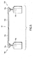
- the slide mechanisms 14a and 14b are at the positions as shown in FIG. 5 .
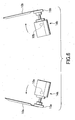
- the driving mechanisms 12a and 12b comprising the rotary actuators rotate the shafts 16a and 16b, as shown in FIG. 6 , the divisional pieces 10a and 10b of the cover 10 pivot together with the slide mechanisms 14a and 14b and the shafts 16a and 16b, so that the cover 10 is opened.
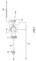
- the driving mechanism 12a comprising the rotary actuator is driven when air is supplied to it through a pipe 30, as shown in the piping diagram in FIG. 7 .
- the driving mechanism 12a is actually driven when a controller (not shown) controls a solenoid valve 31 provided to the pipe.
- the driving mechanism 12b has completely the same arrangement.
- Reference numeral 32 denotes a regulator.
- N 2 gas is introduced into the casing 13 and the base boxes 25 in the slide mechanisms 14a and 14b through pipes 33.
- An outer tank 8 for receiving the overflowing process liquid is arranged outside the cleaning tank 2.
- a process liquid supply pipe 40 for supplying the process liquid is connected to the nozzles 3 in the cleaning tank 2.
- a process liquid supply unit 41 is arranged at the other end of the process liquid supply pipe 40.
- the process liquid supply unit 41 has an ammonia supply source 42 for supplying ammonia, a DHF supply source 43 for supplying diluted hydrofluoric acid (DHF), a DIW supply source 44 for supplying purified water (DIW), and a rinsing liquid supply source 45 for supplying a rinsing liquid such as isopropyl alcohol (IPA).
- IPA isopropyl alcohol
- Pipes 46, 47, 48, and 49 extending from the supply sources 42, 43, 44, and 45 are connected to the process liquid supply pipe 40 through switching valves 51, 52, 53, and 54, respectively.
- switching valves 51, 52, 53, and 54 ammonia, diluted hydrofluoric acid (DHF), purified water (DIW), and rinsing liquid can be selectively supplied as the process liquid to the cleaning tank 2.
- DHF diluted hydrofluoric acid
- DIW purified water
- rinsing liquid can be selectively supplied as the process liquid to the cleaning tank 2.
- the process liquid supply pipe 40 is provided with a pump 57, a damper 58, a heater 59, a filter 60, and an switching valve 61 sequentially from the upstream side.
- a pump 57 Upon operating the pump 57, a predetermined process liquid is supplied toward the cleaning tank 2.
- the heater 59 heats the process liquid to a predetermined temperature.
- the filter 60 removes impurities in the process liquid. Then, the process liquid is supplied to the cleaning tank 2.
- Process liquid discharge pipes 62 and 63 are connected to the bottom of the cleaning tank 2 and the center of the bottom of the outer tank 8, respectively.
- Switching valves 64 and 65 are respectively connected to the process liquid discharge pipes 62 and 63.
- the switching valves 64 and 65 are opened for discharging the process liquid stored in the cleaning tank 2 and outer tank 8 through the process liquid discharge pipes 62 and 63. After that, the switching valves 64 and 65 are closed, and the next process liquid is supplied into the cleaning tank 2.
- the respective constituent portions of the cleaning apparatus as described above e.g., the switching valves provided to the respective pipes, the pump 57, the transfer mechanism for the wafers W, the driving mechanisms 12a and 12b for opening/closing the cover, and the like are connected to a process controller (control mechanism) 70 and controlled by it.
- the process controller 70 is connected to a user interface 71 comprising a keyboard through which the process manager inputs commands for managing the cleaning apparatus, a display for visually displaying the operation status of the cleaning apparatus, and the like.
- the process controller 70 is also connected to a storage portion 72 which stores a control program for implementing the respective types of processes to be performed by the cleaning apparatus by control operation of the process controller 70, and a program, i.e., a recipe, for causing the respective constituent portions to perform the process in accordance with the processing conditions.
- the recipe may be stored in a hard disk or a semiconductor memory.
- the recipe may be stored in a portable storage medium such as a CDROM, a DVD, or the like, and the portable storage medium may be set at a predetermined position in the storage portion 72.
- the recipe may be transferred appropriately from another apparatus via, e.g., a dedicated line.
- an arbitrary recipe is called from the storage portion 72 and performed by the process controller 70, thereby performing a desired process in the cleaning apparatus under the control of the process controller 70.
- FIG. 9 is a diagram for explaining an example of the process sequence and cover opening/closing operation
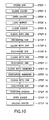
- FIG. 10 is a flowchart of the cleaning process in this case.
- the switching valves 53 and 61 are opened, the pump 57 is driven, and purified water (DIW) is supplied from the DIW supply source 44 into the cleaning tank 2 through the process liquid supply pipe 40 and nozzles 3, thereby filling the cleaning tank 2 with the purified water (DIW) (STEP 1).
- the cover opening/closing mechanism 20 keeps the cover 10 closed until the wafers W are immersed (STEP 2).
- the cover opening/closing mechanism 20 opens the cover 10 (STEP 3). While the wafer holding portion 5 of the wafer holding member 4 is located above the cleaning tank 2, a plurality of, e.g., 50, wafers W are transferred by a transfer mechanism (not shown) to the wafer holding portion 5. A driving mechanism (not shown) moves the wafer holding member 4 downward, so the wafers W are immersed in the purified water (DIW) (STEP 4).
- DIW purified water
- the driving mechanisms 12a and 12b comprising the rotary actuators rotate the shafts 16a and 16b, thereby pivoting the divisional pieces 10a and 10b through the slide mechanisms 14a and 14b, as shown in FIG. 6 .
- the cover opening/closing mechanism 20 closes the cover 10, so the liquid surface is covered with the cover (STEP 5).
- the shafts 16a and 16b in the state shown in FIG. 6 of the rotary actuators 12a and 12b are rotated to change to the state shown in FIG. 5 .
- the slide mechanisms 14a and 14b can move the cover 10 such that the cover 10 follows the liquid surface of the purified water.
- cleaning with the purified water (DIW) is performed while letting the purified water (DIW) overflow from the cleaning tank 2 (STEP 6).
- the switching valves 64 and 65 are opened, and the purified water (DIW) is discharged from the cleaning tank 2 and outer tank 8 through the process liquid discharge pipes 62 and 63 (STEP 7). Then, the switching valve 52 is opened. Diluted hydrofluoric acid (DHF) is supplied from the diluted hydrofluoric acid (DHF) supply source 43 into the cleaning tank 2. The cleaning process is performed while letting diluted hydrofluoric acid (DHF) overflow (STEP 8).
- DHF Diluted hydrofluoric acid
- DHF diluted hydrofluoric acid
- diluted hydrofluoric acid (DHF) is discharged from the cleaning tank 2 and outer tank 8 in accordance with the same procedure as in STEP 7 (STEP 9).
- purified water (DIW) is supplied into the cleaning tank 2 in accordance with the same procedure as in STEP 1.
- a cleaning process is performed while letting the purified water (DIW) overflow (STEP 10).
- the purified water (DIW) is discharged from the cleaning tank 2 and outer tank 8 in accordance with the same procedure as in STEP 7 (STEP 11). Then, the switching valve 51 is opened, and ammonia is supplied from the ammonia supply source 42 into the cleaning tank 2. A cleaning process is performed while letting ammonia overflow (STEP 12).
- the purified water (DIW) is discharged from the cleaning tank 2 and outer tank 8 in accordance with the same procedure as in STEP 7 (STEP 15). Then, the switching valve 54 is opened. A rinsing liquid is supplied from the rinsing liquid supply source 45 into the cleaning tank 2, thereby performing a rinsing process (STEP 16).
- the cover opening/closing mechanism 20 opens the cover (STEP 17).
- the wafer holding member 4 is moved to above the cleaning tank 2.
- the plurality of wafers held by the wafer holding portion 5 are transferred to the transfer mechanism (not shown) (STEP 18).
- the cover 10 always covers the liquid surface of the cleaning tank 2 except for loading and unloading of the wafers W.
- the slide mechanisms 14a and 14b move the cover 10 such that the cover 10 can follow the liquid surface. Therefore, the cover 10 can always be in contact with the liquid surface. This suppresses any gas to be in contact with that portion of the liquid surface where the cover 10 exists. Therefore, the cleaning process is prevented from becoming less uniform due to a gas dissolving into the process liquid. More specifically, this cleaning process is typically performed in air. Without the cover, oxygen in air dissolves into the process liquid and adversely affects the cleaning process. This hardly occurs in this embodiment.
- the cover opening/closing mechanism 20 has the driving mechanisms 12a and 12b comprising the rotary actuators.
- the driving mechanisms 12a and 12b respectively rotate the shafts 16a and 16b, thereby pivoting the divisional pieces 10a and 10b of the cover 10 together with the slide mechanisms 14a and 14b.
- the cover 10 can be opened/closed with such a comparatively simple mechanism and simple operation.
- the follow-up mechanism the slide mechanisms,which are moved for allowing the cover to follow the liquid surface are provided. Therefore, the facilities do not become bulky. When loading and unloading the wafers W, the cover 10 does not interfere with the wafers W.
- the cover 10 covers the liquid surface during the period except for loading and unloading of the wafers W.
- the cover 10 need not always cover the liquid surface during the entire processing period. More specifically, if dissolution of the gas does not largely adversely affect the cleaning process and covering the liquid surface with the cover may undesirably disorder the liquid, the process may be performed with the cover open.
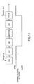
- the influence of diluted hydrofluoric acid (DHF) upon coming into contact with a gas is comparatively small. Depending on the conditions, existence of the cover may impair the uniformity of the liquid flow. Therefore, of the processing sequence described above, as shown in FIG. 11 , the processes until the diluted hydrofluoric acid (DHF) process may be performed with the cover 10 open.
- DHF diluted hydrofluoric acid
- the cover When performing the partial chemical process with the cover closed, the cover is preferably kept closed continuously from the purified water (DIW) process prior to the chemical process. This can prevent the chemical liquid more effectively from coming into contact with the gas.
- the cover 10 is closed prior to the purified water (DIW) process before the ammonia process. This can minimize contact of ammonia in the cleaning tank 2 with the gas in the ammonia process.
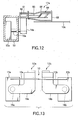
- FIG. 12 is a partially sectional side view for explaining the arrangement of a cover opening/closing mechanism according to this modification
- FIG. 13 is a front view of the cover opening/closing mechanism according to this modification.
- a cover opening/closing mechanism 20' has the casing 13 and the driving mechanisms 12a and 12b comprising rotary actuators, which are arranged in the same manner as in the above cover opening/closing mechanism 20.
- the cover opening/closing mechanism 20' also has lifter mechanisms 17a and 17b and pivotal members 18a and 18b.
- the lifter mechanisms 17a and 17b move the divisional pieces 10a and 10b between a position where they can follow the liquid surface, and a position above the liquid surface.
- the pivotal members 18a and 18b are respectively attached to the shafts 16a and 16b of the driving mechanisms 12a and 12b, support the lifter mechanisms 17a and 17b, and pivot when the shafts 16a and 16b rotate, thereby pivoting the divisional pieces 10a and 10b through the lifter mechanisms 17a and 17b.
- the lifter mechanism 17a has a casing 81 fixed to the upper end of the pivotal member 18a, a cylinder mechanism 82 arranged in the casing 81 and comprising a piston 83 which advances/retracts in the horizontal direction, a parallelogram linkage 84 which can be moved by the piston 83, a connection member 85 for connecting one horizontal link of the parallelogram linkage 84 to the divisional piece 10a of the cover 10, and a flexible casing 86 for covering the parallelogram linkage 84.
- the parallelogram linkage 84 is set free, as shown in FIGS. 12 and 13 , and the divisional piece 10a can move such that it follows the liquid surface of the cleaning tank 2.
- the lifter mechanism 17b has completely the same arrangement.
- the parallelogram linkages 84 also serve as a mechanism for moving the cover 10 such that the cover 10 follows the liquid surface.
- the driving mechanism 12a comprising the rotary actuator and the cylinder mechanism 82 of the lifter mechanism 17a are driven when air is supplied to them through a pipe 90, as shown in the piping diagram of FIG. 16 .
- the driving mechanism 12a is driven by controlling a solenoid valve 91 provided to the pipe by a controller (not shown), and the cylinder mechanism 82 is driven by controlling a solenoid valve 92 provided to the pipe by a controller (not shown).
- Reference numeral 93 denotes a regulator.
- N 2 gas is supplied into the casings 13, 81, and 86 through a pipe 94.
- the parallelogram linkages 84 of the lifter mechanisms 17a and 17b are set free, so the divisional pieces 10a and 10b of the cover 10 can follow the liquid surface, as shown in FIGS. 12 and 13 .
- the pistons 83 of the cylinder mechanisms 82 of the lifter mechanisms 17a and 17b are retracted for setting the vertical links of the parallelogram linkages 84 upright.
- the divisional pieces 10a and 10b are moved to above the liquid surface through the connection member 85, so they are set in the state in FIGS. 14 and 15 .
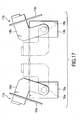
- the shafts 16a and 16b of the driving mechanisms 12a and 12b are rotated outward for pivoting the divisional pieces 10a and 10b through the pivotal members 18a and 18b and lifter mechanisms 17a and 17b, thereby achieving the state as shown in FIG. 17 .
- the cover 10 is opened by two operations, i.e., the operation of moving the divisional pieces 10a and 10b upward and the operation of pivoting them.
- the parallelogram linkages 84 of the lifter mechanisms 17a and 17b enable the cover 10 to follow the liquid surface.
- the cover 10 can always be in contact with the liquid surface, and contact of any gas with that portion of the liquid surface where the cover 10 exists is suppressed. This can prevent dissolution of the gas into the process liquid, thus preventing the cleaning process from being less uniform.
- the shafts 16a and 16b of the driving mechanisms 12a and 12b are rotated for pivoting the divisional pieces 10a and 10b of the cover 10 together with the pivotal members 18a and 18b and the lifter mechanisms 17a and 17b.
- the cover 10 can be opened/closed with this comparatively simple mechanism and simple operation.
- the follow-up mechanisms the parallelogram linkages which are moved for allowing the cover to follow the liquid surface are provided.
- the facilities do not become bulky.
- the cover 10 does not interfere with the wafers W.
- its divisional pieces 10a and 10b are pivoted after they are temporarily moved upward from the liquid surface. This can avoid inconveniences such as splashing the process liquid or disordering the liquid surface.
- a mechanism that moves the divisional pieces 10a and 10b upward can similarly be provided.
- its divisional pieces 10a and 10b can be pivoted after they are temporarily moved upward from the liquid surface.
- the present invention is not limited to the above embodiment, and various changes and modifications may be made within the spirit and scope of the invention.
- the above embodiment is exemplified by a one-path cleaning apparatus.
- the present invention is not limited to this, but can be applied to any cleaning apparatus of the type that cleans a target object while letting the process liquid overflow from the cleaning tank.
- the cover is of a divisional type divided into halves.
- the cover may comprise a single cover.
- a cover opening/closing mechanism, a follow-up mechanism, and the like having the same arrangements as those described above may be provided to only one side of the cover.
- the cover divided into halves opens like so-called double doors.
- the cover may be opened by other methods, e.g., sliding or folding.
- the number to divide the cover is not limited to 2, but may be 3 or more.
- rotary actuators are used as the driving mechanisms used when opening the cover.
- the present invention is not limited to this.
- the mechanism that causes the cover to follow the liquid surface is not limited to that described in the above example.
- a slide mechanism or a parallelogram linkage which is moved for allowing the cover to follow the liquid surface is employed as the follow-up mechanism.
- the cleaning tank may be provided with a liquid level sensor.
- the follow-up mechanism may be driven actively on the basis of the liquid level detected by the liquid level sensor.
- the follow-up mechanism may be actively controlled on the basis of a value obtained by monitoring the injection amount of process liquid, or the value of the injection amount prescribed in the recipe.
- the cover moves vertically such that it follows the liquid surface.
- the cover may move differently, e.g., may slide on the liquid surface.
- the chemical liquids are not limited to those described above, but various types of chemical liquids can be employed.
- semiconductor wafers are employed as the target objects.
- the present invention can similarly be applied to the cleaning process for other target objects, e.g., liquid crystal display (LCD) substrates.
- LCD liquid crystal display
- the present invention is suitable to a cleaning process in general in which a target object such as a semiconductor wafer is immersed in a cleaning liquid and is cleaned while letting the cleaning liquid overflow.
Landscapes
- Cleaning Or Drying Semiconductors (AREA)
- Cleaning By Liquid Or Steam (AREA)
Abstract
Description
- The present invention relates to a cleaning apparatus and a cleaning method for cleaning a target object by immersing it in a chemical liquid in a chemical tank which stores the chemical liquid for cleaning, and a computer readable storage medium for implementing the cleaning method.
- For example, in a semiconductor device manufacturing process, devices such as transistors are formed on a semiconductor wafer (to be merely referred to as a wafer hereinafter) by various processes. If contaminants such as particles, organic contaminants, and/or metal impurities are present on the surface of the devices, it degrades the performance of the devices. Hence, the wafer must be cleaned for removing the contaminants. As such a wafer cleaning process, a process of storing a predetermined cleaning liquid in a cleaning tank and immersing a wafer in the cleaning liquid is employed often. This cleaning process is advantageous in that it can effectively remove the particles attached to the wafer.
- The cleaning process using such a cleaning tank employs a cleaning apparatus in which a large number of chemical tanks for cleaning wafers in a batch manner using various types of chemical liquids, and a large number of purified water cleaning tanks are arranged alternately, thereby enabling a continuous batch process.
- Demands for minimizing the space where the entire cleaning system is installed, decreasing the total cost, and the like arise recently, and a so-called one-path cleaning apparatus attracts attention (for example, see patent document 1). In a multi-tank cleaning apparatus as described above, chemical tanks and purified water cleaning tanks are arranged alternately to correspond to the respective processes. Unlike the multi-tank cleaning apparatus, the one-path cleaning apparatus has a function of supplying and discharging one or a plurality of chemical liquids and purified water to and from one cleaning tank, so that a plurality of processes are performed in the single tank. The one-path cleaning apparatus performs cleaning while supplying each chemical liquid into the chemical tank from a chemical liquid supply nozzle provided to the lower portion of the chemical tank and letting the chemical liquid overflow.
- When performing the cleaning process in this manner, usually, the liquid surface is in contact with a gas in the tank. Hence, convection of the chemical liquid during the overflow undesirably dissolves the gas into the chemical liquid. When the gas dissolves into the chemical liquid in this manner, the cleaning process becomes less uniform. This problem is not limited in the one-path cleaning apparatus, but exists not a little in any cleaning apparatus that uses a cleaning tank.
Patent Document 1: Jpn. Pat. Appln. KOKAI Publication No.10-289894 - It is an object of the present invention to provide a cleaning apparatus and a cleaning method which can improve uniformity in the cleaning process by suppressing dissolution of a gas into a chemical liquid stored in a chemical tank.
It is another object of the present invention to provide a computer readable storage medium for implementing such a cleaning method. - According to a first aspect of the present invention, there is provided a cleaning apparatus comprising: a cleaning tank configured to store a process liquid used for cleaning a target object; a target object holding mechanism configured to hold the target object in the cleaning tank; and a process liquid supply mechanism configured to supply the process liquid to the cleaning tank, wherein the process liquid is supplied to the processing tank while the target object is arranged in the cleaning tank, so the target object is immersed in the process liquid, and the target object is cleaned while letting the process liquid overflow from the cleaning tank, the apparatus further comprising a cover configured to cover a liquid surface in the cleaning tank, a support member configured to support the cover, and a follow-up mechanism configured to move the cover such that the cover follows the liquid surface while the cover is supported by the support member.
- In the first aspect of the present invention, the follow-up mechanism may operate to vertically move such that the follow-up mechanism follows at least the liquid surface. The follow-up mechanism may be moved to allow the cover to follow the liquid surface.
- The cleaning apparatus may further comprise an opening/closing mechanism configured to open/close the cover. In this case, the cleaning apparatus may be arranged such that the process liquid supply mechanism is configured to selectively supply a plurality of process liquids to the cleaning tank; the cleaning apparatus further comprises a process liquid discharge mechanism configured to discharge the process liquid from the cleaning tank, and a control mechanism configured to control supply and discharge of the process liquid and opening and closing of the cover; and the control mechanism serves to control such that the cover is closed in at least part of a period of the plurality of processes in accordance with a processing sequence of the plurality of processes that are performed continuously while using a plurality of process liquids alternately in the cleaning tank. Further, the cover may be divided into two divisional pieces, and the cover opening/closing mechanism may include two driving mechanisms configured to open/close the cover by pivoting the two divisional pieces. In this case, the cleaning apparatus may be arranged such that the follow-up mechanism constitutes part of the cover opening/closing mechanism, and is arranged between the two driving mechanisms and the two divisional pieces, such that the follow-up mechanism is pivoted by the driving mechanisms together with the divisional pieces.
- In the first aspect, the follow-up mechanism may include a slide mechanism or a parallelogram linkage mechanism. The cover opening/closing mechanism may further include a moving mechanism configured to move between a position for allowing the cover to follow the liquid surface and a position above the liquid surface, and the moving mechanism serves to move the cover upward when opening the cover.
- In the first aspect, the cleaning apparatus may be arranged such that the cover is divided into two divisional pieces; the follow-up mechanism constitutes part of the cover opening/closing mechanism; the cover opening/closing mechanism includes two driving mechanisms configured to pivot the two divisional pieces respectively, two pivotal members attached to shafts of the two driving mechanisms and pivoted by the two driving mechanisms, two parallelogram linkages provided to the two driving mechanisms correspondingly for serving each as the follow-up mechanism and configured to support the two divisional pieces, respectively, and two cylinder mechanisms respectively attached to the two pivotal members and configured to move the two parallelogram linkages between a position for allowing the two parallelogram linkages to follow the liquid surface of the cover and a position above the liquid surface; and the two driving mechanisms is configured to pivot the two divisional pieces together with the two pivotal mechanisms, the two cylinder mechanisms, and the two parallelogram linkages, after the two cylinder mechanisms move the two parallelogram linkages to the position above the liquid surface, thereby opening the cover.
- According to a second aspect of the present invention, there is provided a cleaning method for performing a cleaning process using a cleaning apparatus comprising a cleaning tank configured to store a process liquid used for cleaning a target object, a target object holding mechanism configured to hold the target object in the cleaning tank, a process liquid supply mechanism configured to supply the process liquid to the cleaning tank, a process liquid discharge mechanism configured to discharge the process liquid from the cleaning tank, and a cover configured to cover a liquid surface in the cleaning tank, the method comprising: arranging a target object in the cleaning tank, supplying the process liquid to the processing tank where the target object is arranged, thereby immersing the target object in the process liquid; and cleaning the target object while letting the process liquid overflow from the cleaning tank, wherein when cleaning the target object while letting the process liquid overflow, the cover is caused to follow the liquid surface.
- In the second aspect of the present invention, the cleaning method may be arranged such that the cover is openable/closeable, a plurality of process liquids are used alternately in the cleaning tank for continuously performing a plurality of processes, and the cover is kept closed in at least part of a period of the plurality of processes in accordance with a processing sequence of the plurality of processes.
- According to a third aspect of the present invention, there is provided a computer readable storage medium that stores a control program for execution on a computer for controlling a cleaning apparatus comprising a cleaning tank configured to store a process liquid used for cleaning a target object, a target object holding mechanism configured to hold the target object in the cleaning tank, a process liquid supply mechanism configured to supply the process liquid to the cleaning tank, a process liquid discharge mechanism configured to discharge the process liquid from the cleaning tank, and a cover configured to cover a liquid surface in the cleaning tank, wherein the control program, when executed, causes the computer to control a cleaning apparatus to conduct a cleaning method comprising arranging a target object in the cleaning tank, supplying the process liquid to the processing tank where the target object is arranged, thereby immersing the target object in the process liquid; and cleaning the target object while letting the process liquid overflow from the cleaning tank, wherein when cleaning the target object while letting the process liquid overflow, the cover is caused to follow the liquid surface.
- According to the present invention, when cleaning a target object by letting a process liquid overflow while the target object is kept immersed in the process liquid in a cleaning tank, a cover for covering a liquid surface in the cleaning tank, a support member for supporting the cover, and a follow-up mechanism for moving the cover such that the cover follows the liquid surface while the cover is supported by the support member are provided. Thus, the cover can be brought into tight contact with the liquid surface during the cleaning process, and contact of a gas with the process liquid can be minimized. This can decrease dissolution of the gas into the process liquid, thereby improving uniformity in the cleaning process.
- It may be arranged such that the cover can be opened and closed, and a plurality of process liquids can be supplied to the cleaning tank. With this arrangement, in performing a plurality of processes continuously by using a plurality of process liquids alternately in the cleaning tank, the cover can be controlled to be closed at least during some period in the plurality of processes in accordance with the process sequence of the plurality of processes. Specifically, where a cleaning process is less affected by gas dissolution while covering the liquid surface with the cover can disorder the liquid, the cover may be kept open. In this case, only where a cleaning process is substantially affected by gas dissolution, the cover is closed.
-
- [
FIG. 1 ] This is a plan view showing a cleaning apparatus according to an embodiment of the present invention; - [
FIG. 2 ] This is a sectional view taken along the line A-A ofFIG. 1 ; - [
FIG. 3 ] This is a sectional view taken along the line B-B ofFIG. 1 ; - [
FIG. 4 ] This is a sectional view showing the arrangement of a slide mechanism as a constituent element of a pivotal mechanism in the cleaning apparatus shown inFIGS. 1 to 3 ; - [
FIG. 5 ] This is a front view schematically showing a state in which a cover covers a liquid surface in the cleaning apparatus shown inFIGS. 1 to 3 ; - [
FIG. 6 ] This is a front view schematically showing a state in which the cover is open in the cleaning apparatus shown inFIGS. 1 to 3 ; - [
FIG. 7 ] This is a view showing a piping diagram of air for driving a driving mechanism in the cover opening/closing mechanism of the cleaning apparatus shown inFIGS. 1 to 3 and a piping diagram of N2 gas to be introduced to a casing; - [
FIG. 8 ] This is a schematic view showing supply and discharge of a process liquid in the cleaning apparatus and control of the cleaning apparatus according to the embodiment of the present invention; - [
FIG. 9 ] This is a diagram for explaining an example of the process sequence and cover opening/closing operation in the cleaning process performed in the cleaning apparatus according to the embodiment of the present invention; - [
FIG. 10 ] This is a flowchart of the cleaning process in the cleaning apparatus according to the embodiment of the present invention; - [
FIG. 11 ] This is a diagram for explaining another example of the cover opening/closing operation in the process sequence shown inFIG. 9 ; - [
FIG. 12 ] This is a partially sectional side view showing a modification of the cover opening/closing mechanism; - [
FIG. 13 ] This is a front view of the modification of the cover opening/closing mechanism; - [
FIG. 14 ] This is a partially sectional side view showing a state in which the cover located on the liquid surface is moved upward in the modification of the cover opening/closing mechanism; - [
FIG. 15 ] This is a front view showing a state in which the cover located on the liquid surface is moved upward in the modification of the cover opening/closing mechanism; - [
FIG. 16 ] This is a view showing a piping diagram of air for driving a driving mechanism comprising a rotary actuator and a cylinder mechanism and a piping diagram of N2 gas to be introduced to a casing, in the modification of the cover opening/closing mechanism; and - [
FIG. 17 ] This is a front view showing a state in which the cover is open in the modification of the cover opening/closing mechanism. - An embodiment of the present invention will be described in detail. This embodiment will be exemplified by a case in which the present invention is applied to a one-path cleaning apparatus.
FIG. 1 is a plan view showing a cleaning apparatus according to an embodiment of the present invention,FIG. 2 is a sectional view taken along the line A-A of the same, andFIG. 3 is a sectional view taken along the line B-B of the same. - The cleaning apparatus according to this embodiment has a
housing 1 and acleaning tank 2 arranged in thehousing 1. A predetermined process liquid is to be stored in thecleaning tank 2. As will be described later, the predetermined process liquid is supplied from a predetermined supply source into thecleaning tank 2 through nozzles 3 (seeFIGS. 2 and3 ) provided in thecleaning tank 2 and serving as a process liquid supply mechanism, thereby storing the process liquid in thecleaning tank 2. A plurality of wafers W are immersed in the process liquid, and a cleaning process takes place while the process liquid overflows from thecleaning tank 2. The overflowing process liquid flows to an outer tank (not shown). - In the
cleaning tank 2, awafer holding member 4 holds a plurality of, e.g., 50 wafers W. Thewafer holding member 4 has awafer holding portion 5 for holding the wafers W upright in the horizontal direction, and asupport 6 extending from the end of thewafer holding portion 5 upward along the inner wall of thecleaning tank 2 to support thewafer holding portion 5. A driving mechanism (not shown) vertically moves thewafer holding portion 5 through thesupport 6, thereby loading/unloading the wafers W into/from thecleaning tank 2. The wafers W are transferred to thewafer holding member 4 by an appropriate transfer unit. Thewafer holding portion 5 has first holdingrods 5a for holding the wafers W at portions near their lower ends, andsecond holding rods 5b for holding the wafers W at portions slightly above the portions held by thefirst holding rods 5a. The first andsecond holding rods - A
cover 10 is arranged on the liquid surface of thecleaning tank 2 to be capable of following the liquid surface and being opened/closed. Thecover 10 is halved intodivisional pieces closing mechanism 20 pivots thedivisional pieces cover 10. The mating surfaces of thedivisional pieces divisional pieces - The cover opening/
closing mechanism 20 has acasing 13, drivingmechanisms divisional pieces slide mechanisms FIGS. 2 and4 ). The drivingmechanisms mechanisms rotatable shafts slide mechanisms mechanisms shafts divisional pieces slide mechanisms support plates cover 10 is made of, e.g., a fluoroplastic, and floats on the surface of the process liquid. When theslide mechanisms cover 10 can follow the liquid surface in thecleaning tank 2. Namely, theslide mechanisms cover 10 to follow the liquid surface. - The
cover 10 serves to prevent the cleaning process from becoming less uniform due to a gas dissolving into the process liquid, and preferably covers the liquid surface in thecleaning tank 2 as large an area as possible. However, the process liquid must overflow from thecleaning tank 2. If the cover is present in the overflowing portion, it interferes with the overflowing. Also, a space for thesupport member 6 of thewafer holding member 4 must be reserved. - As shown in
FIG. 4 , theslide mechanism 14a comprises abase box 25 fixed to theshaft 16a horizontally extending from thedriving mechanism 12a, ashaft 21 having one end fixed to thesupport plate 15a and extending in thebase box 25, alinear bush 22 arranged in thebase box 25 and serving to guide theshaft 21 to be linearly movable, abracket 23 arranged under thelinear bush 22 and serving to stop theshaft 21 at an arbitrary position, and astopper 24 of theshaft 21 arranged under thebracket 23. Theslide mechanism 14b has completely the same arrangement. - As the
slide mechanisms cover 10 covers the liquid surface and is floated by the buoyancy of the process liquid, even if the liquid level changes, theslide mechanisms cover 10 such that the cover follows the change in the liquid level. - When the
cover 10 covers the liquid surface, theslide mechanisms FIG. 5 . When the drivingmechanisms shafts FIG. 6 , thedivisional pieces cover 10 pivot together with theslide mechanisms shafts cover 10 is opened. - The
driving mechanism 12a comprising the rotary actuator is driven when air is supplied to it through apipe 30, as shown in the piping diagram inFIG. 7 . Thedriving mechanism 12a is actually driven when a controller (not shown) controls asolenoid valve 31 provided to the pipe. Thedriving mechanism 12b has completely the same arrangement.Reference numeral 32 denotes a regulator. In order to prevent oxidation or the like of the driving unit, N2 gas is introduced into thecasing 13 and thebase boxes 25 in theslide mechanisms pipes 33. - Supply and discharge of the process liquid in the cleaning apparatus of this embodiment, and control of the cleaning apparatus will be described with reference to
FIG. 8 .
Anouter tank 8 for receiving the overflowing process liquid is arranged outside thecleaning tank 2. A processliquid supply pipe 40 for supplying the process liquid is connected to thenozzles 3 in thecleaning tank 2. A processliquid supply unit 41 is arranged at the other end of the processliquid supply pipe 40. The processliquid supply unit 41 has anammonia supply source 42 for supplying ammonia, aDHF supply source 43 for supplying diluted hydrofluoric acid (DHF), aDIW supply source 44 for supplying purified water (DIW), and a rinsingliquid supply source 45 for supplying a rinsing liquid such as isopropyl alcohol (IPA).Pipes supply sources liquid supply pipe 40 through switchingvalves valves cleaning tank 2. - The process
liquid supply pipe 40 is provided with apump 57, adamper 58, aheater 59, afilter 60, and an switchingvalve 61 sequentially from the upstream side. Upon operating thepump 57, a predetermined process liquid is supplied toward thecleaning tank 2. Theheater 59 heats the process liquid to a predetermined temperature. Thefilter 60 removes impurities in the process liquid. Then, the process liquid is supplied to thecleaning tank 2. - Process
liquid discharge pipes cleaning tank 2 and the center of the bottom of theouter tank 8, respectively. Switchingvalves liquid discharge pipes valves cleaning tank 2 andouter tank 8 through the processliquid discharge pipes valves cleaning tank 2. - The respective constituent portions of the cleaning apparatus as described above, e.g., the switching valves provided to the respective pipes, the
pump 57, the transfer mechanism for the wafers W, the drivingmechanisms process controller 70 is connected to auser interface 71 comprising a keyboard through which the process manager inputs commands for managing the cleaning apparatus, a display for visually displaying the operation status of the cleaning apparatus, and the like. - The
process controller 70 is also connected to astorage portion 72 which stores a control program for implementing the respective types of processes to be performed by the cleaning apparatus by control operation of theprocess controller 70, and a program, i.e., a recipe, for causing the respective constituent portions to perform the process in accordance with the processing conditions. The recipe may be stored in a hard disk or a semiconductor memory. Alternatively, the recipe may be stored in a portable storage medium such as a CDROM, a DVD, or the like, and the portable storage medium may be set at a predetermined position in thestorage portion 72. Also, the recipe may be transferred appropriately from another apparatus via, e.g., a dedicated line. - As needed, upon instruction from the
user interface 71, an arbitrary recipe is called from thestorage portion 72 and performed by theprocess controller 70, thereby performing a desired process in the cleaning apparatus under the control of theprocess controller 70. - An example of the processing operation in the cleaning apparatus having the above arrangement will be described.
The following explanation will be given of a case where the wafers W are to be cleaned with diluted hydrofluoric acid and then cleaned with ammonia.FIG. 9 is a diagram for explaining an example of the process sequence and cover opening/closing operation, andFIG. 10 is a flowchart of the cleaning process in this case. - First, in an empty state of the
cleaning tank 2, the switchingvalves pump 57 is driven, and purified water (DIW) is supplied from theDIW supply source 44 into thecleaning tank 2 through the processliquid supply pipe 40 andnozzles 3, thereby filling thecleaning tank 2 with the purified water (DIW) (STEP 1). The cover opening/closing mechanism 20 keeps thecover 10 closed until the wafers W are immersed (STEP 2). - Subsequently, the cover opening/
closing mechanism 20 opens the cover 10 (STEP 3). While thewafer holding portion 5 of thewafer holding member 4 is located above thecleaning tank 2, a plurality of, e.g., 50, wafers W are transferred by a transfer mechanism (not shown) to thewafer holding portion 5. A driving mechanism (not shown) moves thewafer holding member 4 downward, so the wafers W are immersed in the purified water (DIW) (STEP 4). When opening thecover 10 with the cover opening/closing mechanism 20, the drivingmechanisms shafts divisional pieces slide mechanisms FIG. 6 . - After immersing the wafers W in the process liquid in the
cleaning tank 2, the cover opening/closing mechanism 20 closes thecover 10, so the liquid surface is covered with the cover (STEP 5). In this case, theshafts FIG. 6 of therotary actuators FIG. 5 . In this state, theslide mechanisms cover 10 such that thecover 10 follows the liquid surface of the purified water. After covering the liquid surface with thecover 10, cleaning with the purified water (DIW) is performed while letting the purified water (DIW) overflow from the cleaning tank 2 (STEP 6). - After cleaning with the purified water (DIW) is finished, the switching
valves cleaning tank 2 andouter tank 8 through the processliquid discharge pipes 62 and 63 (STEP 7). Then, the switchingvalve 52 is opened. Diluted hydrofluoric acid (DHF) is supplied from the diluted hydrofluoric acid (DHF)supply source 43 into thecleaning tank 2. The cleaning process is performed while letting diluted hydrofluoric acid (DHF) overflow (STEP 8). - After that, diluted hydrofluoric acid (DHF) is discharged from the
cleaning tank 2 andouter tank 8 in accordance with the same procedure as in STEP 7 (STEP 9). Then, purified water (DIW) is supplied into thecleaning tank 2 in accordance with the same procedure as inSTEP 1. A cleaning process is performed while letting the purified water (DIW) overflow (STEP 10). - After that, the purified water (DIW) is discharged from the
cleaning tank 2 andouter tank 8 in accordance with the same procedure as in STEP 7 (STEP 11). Then, the switchingvalve 51 is opened, and ammonia is supplied from theammonia supply source 42 into thecleaning tank 2. A cleaning process is performed while letting ammonia overflow (STEP 12). - After that, ammonia is discharged from the
cleaning tank 2 andouter tank 8 in accordance with the same procedure as in STEP 7 (STEP 13). Then, purified water (DIW) is supplied into thecleaning tank 2 in accordance with the same procedure as inSTEP 1. A cleaning process is performed while letting the purified water (DIW) overflow (STEP 14). - After that, the purified water (DIW) is discharged from the
cleaning tank 2 andouter tank 8 in accordance with the same procedure as in STEP 7 (STEP 15). Then, the switchingvalve 54 is opened. A rinsing liquid is supplied from the rinsingliquid supply source 45 into thecleaning tank 2, thereby performing a rinsing process (STEP 16). - After the rinsing process is finished, the cover opening/
closing mechanism 20 opens the cover (STEP 17). Thewafer holding member 4 is moved to above thecleaning tank 2. The plurality of wafers held by thewafer holding portion 5 are transferred to the transfer mechanism (not shown) (STEP 18). - During the above cleaning process, the
cover 10 always covers the liquid surface of thecleaning tank 2 except for loading and unloading of the wafers W. In addition, when thecover 10 is mounted on the liquid surface, theslide mechanisms cover 10 such that thecover 10 can follow the liquid surface. Therefore, thecover 10 can always be in contact with the liquid surface. This suppresses any gas to be in contact with that portion of the liquid surface where thecover 10 exists. Therefore, the cleaning process is prevented from becoming less uniform due to a gas dissolving into the process liquid. More specifically, this cleaning process is typically performed in air. Without the cover, oxygen in air dissolves into the process liquid and adversely affects the cleaning process. This hardly occurs in this embodiment. - According to this embodiment, the cover opening/
closing mechanism 20 has the drivingmechanisms mechanisms shafts divisional pieces cover 10 together with theslide mechanisms cover 10 can be opened/closed with such a comparatively simple mechanism and simple operation. As the follow-up mechanism, the slide mechanisms,which are moved for allowing the cover to follow the liquid surface are provided. Therefore, the facilities do not become bulky. When loading and unloading the wafers W, thecover 10 does not interfere with the wafers W. - In the explanation described above, the
cover 10 covers the liquid surface during the period except for loading and unloading of the wafers W. Thecover 10 need not always cover the liquid surface during the entire processing period. More specifically, if dissolution of the gas does not largely adversely affect the cleaning process and covering the liquid surface with the cover may undesirably disorder the liquid, the process may be performed with the cover open. For example, the influence of diluted hydrofluoric acid (DHF) upon coming into contact with a gas is comparatively small. Depending on the conditions, existence of the cover may impair the uniformity of the liquid flow. Therefore, of the processing sequence described above, as shown inFIG. 11 , the processes until the diluted hydrofluoric acid (DHF) process may be performed with thecover 10 open. When performing the partial chemical process with the cover closed, the cover is preferably kept closed continuously from the purified water (DIW) process prior to the chemical process. This can prevent the chemical liquid more effectively from coming into contact with the gas. In the example ofFIG. 11 , thecover 10 is closed prior to the purified water (DIW) process before the ammonia process. This can minimize contact of ammonia in thecleaning tank 2 with the gas in the ammonia process. - A modification of the cover opening/closing mechanism will be described.
FIG. 12 is a partially sectional side view for explaining the arrangement of a cover opening/closing mechanism according to this modification, andFIG. 13 is a front view of the cover opening/closing mechanism according to this modification. In this case, a cover opening/closing mechanism 20' has thecasing 13 and the drivingmechanisms closing mechanism 20. In addition, the cover opening/closing mechanism 20' also haslifter mechanisms pivotal members lifter mechanisms divisional pieces pivotal members shafts mechanisms lifter mechanisms shafts divisional pieces lifter mechanisms - The
lifter mechanism 17a has acasing 81 fixed to the upper end of thepivotal member 18a, acylinder mechanism 82 arranged in thecasing 81 and comprising apiston 83 which advances/retracts in the horizontal direction, aparallelogram linkage 84 which can be moved by thepiston 83, aconnection member 85 for connecting one horizontal link of theparallelogram linkage 84 to thedivisional piece 10a of thecover 10, and aflexible casing 86 for covering theparallelogram linkage 84. When thepiston 83 is advanced, theparallelogram linkage 84 is set free, as shown inFIGS. 12 and 13 , and thedivisional piece 10a can move such that it follows the liquid surface of thecleaning tank 2. Thelifter mechanism 17b has completely the same arrangement. When theparallelogram linkage 84 is free, thedivisional piece 10b can move such that it can follow the liquid surface of thecleaning tank 2. Namely, theparallelogram linkages 84 also serve as a mechanism for moving thecover 10 such that thecover 10 follows the liquid surface. - When the
pistons 83 of thecylinder mechanisms 82 are retracted from the state shown inFIGS. 12 and 13 , the vertical links of theparallelogram linkages 84 become upright, and thedivisional pieces cover 10 has moved upward from the liquid surface. - The
driving mechanism 12a comprising the rotary actuator and thecylinder mechanism 82 of thelifter mechanism 17a are driven when air is supplied to them through apipe 90, as shown in the piping diagram ofFIG. 16 . In actual driving, thedriving mechanism 12a is driven by controlling asolenoid valve 91 provided to the pipe by a controller (not shown), and thecylinder mechanism 82 is driven by controlling asolenoid valve 92 provided to the pipe by a controller (not shown). This also applies to thedriving mechanism 12b andlifter mechanism 17b.Reference numeral 93 denotes a regulator. To prevent oxidation or the like of the driving unit, N2 gas is supplied into thecasings - In the cover opening/closing mechanism 20' having the above arrangement, when the
cover 10 covers the liquid surface, theparallelogram linkages 84 of thelifter mechanisms divisional pieces cover 10 can follow the liquid surface, as shown inFIGS. 12 and 13 . To open the cover in this state, first, thepistons 83 of thecylinder mechanisms 82 of thelifter mechanisms parallelogram linkages 84 upright. Thus, thedivisional pieces connection member 85, so they are set in the state inFIGS. 14 and 15 . Then, theshafts mechanisms divisional pieces pivotal members lifter mechanisms FIG. 17 . Namely, thecover 10 is opened by two operations, i.e., the operation of moving thedivisional pieces - When closing the
cover 10 again, in the state inFIG. 16 , theshafts mechanisms divisional pieces pivotal members lifter mechanisms FIGS. 14 and 15 . Then, thepistons 83 of thecylinder mechanisms 82 of thelifter mechanisms parallelogram linkages 84 free, so that thedivisional pieces - In the cover opening/closing mechanism 20' as described above, when the
cover 10 is mounted, theparallelogram linkages 84 of thelifter mechanisms cover 10 to follow the liquid surface. Thus, thecover 10 can always be in contact with the liquid surface, and contact of any gas with that portion of the liquid surface where thecover 10 exists is suppressed. This can prevent dissolution of the gas into the process liquid, thus preventing the cleaning process from being less uniform. Theshafts mechanisms divisional pieces cover 10 together with thepivotal members lifter mechanisms cover 10 can be opened/closed with this comparatively simple mechanism and simple operation. Also, as the follow-up mechanisms, the parallelogram linkages which are moved for allowing the cover to follow the liquid surface are provided. Thus, the facilities do not become bulky. When loading and unloading the wafers W, thecover 10 does not interfere with the wafers W. In addition, when opening thecover 10, itsdivisional pieces closing mechanism 20 described above, a mechanism that moves thedivisional pieces cover 10, itsdivisional pieces - The present invention is not limited to the above embodiment, and various changes and modifications may be made within the spirit and scope of the invention. For example, the above embodiment is exemplified by a one-path cleaning apparatus. However, the present invention is not limited to this, but can be applied to any cleaning apparatus of the type that cleans a target object while letting the process liquid overflow from the cleaning tank.
- In the above embodiment, the cover is of a divisional type divided into halves. Alternatively, the cover may comprise a single cover. In this case, a cover opening/closing mechanism, a follow-up mechanism, and the like having the same arrangements as those described above may be provided to only one side of the cover. In the above embodiment, the cover divided into halves opens like so-called double doors.
Alternatively, the cover may be opened by other methods, e.g., sliding or folding. The number to divide the cover is not limited to 2, but may be 3 or more. - In the above embodiment, rotary actuators are used as the driving mechanisms used when opening the cover. However, the present invention is not limited to this.
- The mechanism that causes the cover to follow the liquid surface is not limited to that described in the above example. For example, in the above embodiment, a slide mechanism or a parallelogram linkage which is moved for allowing the cover to follow the liquid surface is employed as the follow-up mechanism. Alternatively, the cleaning tank may be provided with a liquid level sensor. The follow-up mechanism may be driven actively on the basis of the liquid level detected by the liquid level sensor. In addition to the liquid level sensor, the follow-up mechanism may be actively controlled on the basis of a value obtained by monitoring the injection amount of process liquid, or the value of the injection amount prescribed in the recipe.
- In the above embodiment, the cover moves vertically such that it follows the liquid surface. Alternatively, the cover may move differently, e.g., may slide on the liquid surface.
- In the case of the process using the plurality of process liquids described in the above embodiment, the chemical liquids are not limited to those described above, but various types of chemical liquids can be employed. In the embodiment, semiconductor wafers are employed as the target objects. Alternatively, the present invention can similarly be applied to the cleaning process for other target objects, e.g., liquid crystal display (LCD) substrates.
- The present invention is suitable to a cleaning process in general in which a target object such as a semiconductor wafer is immersed in a cleaning liquid and is cleaned while letting the cleaning liquid overflow.
Claims (14)
- A cleaning apparatus comprising:a cleaning tank configured to store a process liquid used for cleaning a target object;a target object holding mechanism configured to hold the target object in the cleaning tank; anda process liquid supply mechanism configured to supply the process liquid to the cleaning tank,wherein the process liquid is supplied to the processing tank while the target object is arranged in the cleaning tank, so the target object is immersed in the process liquid, and the target object is cleaned while letting the process liquid overflow from the cleaning tank,the apparatus further comprisinga cover configured to cover a liquid surface in the cleaning tank,a support member configured to support the cover, anda follow-up mechanism configured to move the cover such that the cover follows the liquid surface while the cover is supported by the support member.
- The cleaning apparatus according to claim 1, wherein the follow-up mechanism operates to vertically move such that the follow-up mechanism follows at least the liquid surface.
- The cleaning apparatus according to claim 1,
wherein the follow-up mechanism is moved to allow the cover to follow the liquid surface. - The cleaning apparatus according to claim 1, further comprising an opening/closing mechanism configured to open/close the cover.
- The cleaning apparatus according to claim 4, wherein
the process liquid supply mechanism is configured to selectively supply a plurality of process liquids to the cleaning tank;
the cleaning apparatus further comprises a process liquid discharge mechanism configured to discharge the process liquid from the cleaning tank, and a control mechanism configured to control supply and discharge of the process liquid and opening and closing of the cover; and
the control mechanism serves to control such that the cover is closed in at least part of a period of the plurality of processes in accordance with a processing sequence of the plurality of processes that are performed continuously while using a plurality of process liquids alternately in the cleaning tank. - The cleaning apparatus according to claim 4, wherein the cover is divided into two divisional pieces, and the cover opening/closing mechanism includes two driving mechanisms configured to open/close the cover by pivoting the two divisional pieces.
- The cleaning apparatus according to claim 6, wherein the follow-up mechanism constitutes part of the cover opening/closing mechanism, and is arranged between the two driving mechanisms and the two divisional pieces, such that the follow-up mechanism is pivoted by the driving mechanisms together with the divisional pieces.
- The cleaning apparatus according to claim 1, wherein the follow-up mechanism includes a slide mechanism.
- The cleaning apparatus according to claim 1, wherein the follow-up mechanism includes a parallelogram linkage mechanism.
- The cleaning apparatus according to claim 1, wherein the cover opening/closing mechanism further includes a moving mechanism configured to move between a position for allowing the cover to follow the liquid surface and a position above the liquid surface, and the moving mechanism serves to move the cover upward when opening the cover.
- The cleaning apparatus according to claim 4, wherein
the cover is divided into two divisional pieces;
the follow-up mechanism constitutes part of the cover opening/closing mechanism;
the cover opening/closing mechanism includes
two driving mechanisms configured to pivot the two divisional pieces respectively,
two pivotal members attached to shafts of the two driving mechanisms and pivoted by the two driving mechanisms,
two parallelogram linkages provided to the two driving mechanisms correspondingly for serving each as the follow-up mechanism and configured to support the two divisional pieces, respectively, and
two cylinder mechanisms respectively attached to the two pivotal members and configured to move the two parallelogram linkages between a position for allowing the two parallelogram linkages to follow the liquid surface of the cover and a position above the liquid surface; and
the two driving mechanisms is configured to pivot the two divisional pieces together with the two pivotal mechanisms, the two cylinder mechanisms, and the two parallelogram linkages, after the two cylinder mechanisms move the two parallelogram linkages to the position above the liquid surface, thereby opening the cover. - A cleaning method for performing a cleaning process using a cleaning apparatus comprising
a cleaning tank configured to store a process liquid used for cleaning a target object,
a target object holding mechanism configured to hold the target object in the cleaning tank,
a process liquid supply mechanism configured to supply the process liquid to the cleaning tank,
a process liquid discharge mechanism configured to discharge the process liquid from the cleaning tank, and
a cover configured to cover a liquid surface in the cleaning tank,
the method comprising:arranging a target object in the cleaning tank,supplying the process liquid to the processing tank where the target object is arranged, thereby immersing the target object in the process liquid; andcleaning the target object while letting the process liquid overflow from the cleaning tank,wherein when cleaning the target object while letting the process liquid overflow, the cover is caused to follow the liquid surface. - The cleaning method according to claim 12, wherein the cover is openable/closeable, a plurality of process liquids are used alternately in the cleaning tank for continuously performing a plurality of processes, and the cover is kept closed in at least part of a period of the plurality of processes in accordance with a processing sequence of the plurality of processes.
- A computer readable storage medium that stores a control program for execution on a computer for controlling a cleaning apparatus comprising a cleaning tank configured to store a process liquid used for cleaning a target object, a target object holding mechanism configured to hold the target object in the cleaning tank, a process liquid supply mechanism configured to supply the process liquid to the cleaning tank, a process liquid discharge mechanism configured to discharge the process liquid from the cleaning tank, and a cover configured to cover a liquid surface in the cleaning tank,
wherein the control program, when executed, causes the computer to control a cleaning apparatus to conduct a cleaning method comprising
arranging a target object in the cleaning tank,
supplying the process liquid to the processing tank where the target object is arranged, thereby immersing the target object in the process liquid; and
cleaning the target object while letting the process liquid overflow from the cleaning tank,
wherein when cleaning the target object while letting the process liquid overflow, the cover is caused to follow the liquid surface.
Applications Claiming Priority (2)
| Application Number | Priority Date | Filing Date | Title |
|---|---|---|---|
| JP2005192725A JP4672464B2 (en) | 2005-06-30 | 2005-06-30 | Cleaning apparatus and cleaning method, and computer-readable storage medium |
| PCT/JP2006/312879 WO2007004485A1 (en) | 2005-06-30 | 2006-06-28 | Washing device and washing method |
Publications (3)
| Publication Number | Publication Date |
|---|---|
| EP1900448A1 true EP1900448A1 (en) | 2008-03-19 |
| EP1900448A4 EP1900448A4 (en) | 2009-05-27 |
| EP1900448B1 EP1900448B1 (en) | 2010-04-14 |
Family
ID=37604354
Family Applications (1)
| Application Number | Title | Priority Date | Filing Date |
|---|---|---|---|
| EP06767496A Not-in-force EP1900448B1 (en) | 2005-06-30 | 2006-06-28 | Washing device and washing method |
Country Status (6)
| Country | Link |
|---|---|
| US (1) | US7900640B2 (en) |
| EP (1) | EP1900448B1 (en) |
| JP (1) | JP4672464B2 (en) |
| DE (1) | DE602006013639D1 (en) |
| TW (1) | TW200707570A (en) |
| WO (1) | WO2007004485A1 (en) |
Families Citing this family (11)
| Publication number | Priority date | Publication date | Assignee | Title |
|---|---|---|---|---|
| JP4630881B2 (en) * | 2007-03-05 | 2011-02-09 | シャープ株式会社 | Substrate cleaning device |
| JP2009080035A (en) | 2007-09-26 | 2009-04-16 | Olympus Corp | Analyzer |
| US20090087566A1 (en) * | 2007-09-27 | 2009-04-02 | Masahiro Kimura | Substrate treating apparatus and substrate treating method |
| JP5179282B2 (en) * | 2007-09-27 | 2013-04-10 | 大日本スクリーン製造株式会社 | Substrate processing apparatus and substrate processing method |
| US9027575B2 (en) * | 2010-12-20 | 2015-05-12 | Unified Brands, Inc. | Fluid screen for pot and pan washing machine |
| DE102012001721A1 (en) * | 2012-01-31 | 2013-08-01 | Rena Gmbh | Method for rinsing of workpiece e.g. carrier of wafer used in e.g. solar cell, involves providing rinsing spacers in nozzle to pump out rinsing fluid from fluid tank and to drip off the rinsing fluid to workpiece |
| TWI569351B (en) * | 2015-04-30 | 2017-02-01 | 環球晶圓股份有限公司 | Wafer rotating device |
| WO2020236803A1 (en) * | 2019-05-23 | 2020-11-26 | Lam Research Corporation | Chamber component cleanliness measurement system |
| CN112058774B (en) * | 2020-08-24 | 2021-11-30 | 台州市亿源塑业有限公司 | Overflow groove structure of wet etching cleaning mechanism |
| CN115328219B (en) * | 2022-07-26 | 2025-03-25 | 海南大学 | An electromagnetic drive control system and method for a flexible mechanism |
| CN120714987A (en) * | 2024-03-27 | 2025-09-30 | 盛美半导体设备(上海)股份有限公司 | Tank cover and substrate liquid treatment tank |
Family Cites Families (15)
| Publication number | Priority date | Publication date | Assignee | Title |
|---|---|---|---|---|
| JP2617610B2 (en) * | 1990-08-16 | 1997-06-04 | 山形日本電気株式会社 | Wafer processing equipment |
| JPH06104234A (en) * | 1992-09-18 | 1994-04-15 | Matsushita Electric Ind Co Ltd | Substrate cleaning equipment |
| JPH0652143U (en) * | 1992-12-25 | 1994-07-15 | 住友シチックス株式会社 | Cleaning equipment |
| US5464480A (en) * | 1993-07-16 | 1995-11-07 | Legacy Systems, Inc. | Process and apparatus for the treatment of semiconductor wafers in a fluid |
| DE4336704A1 (en) * | 1993-10-27 | 1995-05-04 | Wacker Chemitronic | Method and device for treating disc-shaped workpieces with a liquid |
| JP3464843B2 (en) * | 1995-03-30 | 2003-11-10 | 大日本スクリーン製造株式会社 | Substrate processing method and substrate processing apparatus in substrate processing apparatus |
| JP3534211B2 (en) * | 1995-09-29 | 2004-06-07 | 富士写真フイルム株式会社 | Automatic developing system for photosensitive lithographic printing plate |
| JP3336223B2 (en) * | 1997-04-15 | 2002-10-21 | 東京エレクトロン株式会社 | Cleaning system and cleaning method |
| US6050446A (en) * | 1997-07-11 | 2000-04-18 | Applied Materials, Inc. | Pivoting lid assembly for a chamber |
| JP2000031103A (en) * | 1998-07-14 | 2000-01-28 | Sony Corp | Cleaning method, cleaning liquid replacement method, cleaning device and cleaning tank |
| JP2001176833A (en) * | 1999-12-14 | 2001-06-29 | Tokyo Electron Ltd | Substrate processing equipment |
| JP2001338904A (en) * | 2000-05-30 | 2001-12-07 | Konan Koki Kk | Wafer cleaning equipment |
| KR100513397B1 (en) * | 2001-01-12 | 2005-09-09 | 삼성전자주식회사 | semiconductor wafer washing system and washing-solution supply method thereof |
| JP2004358283A (en) * | 2003-05-30 | 2004-12-24 | Seiko Epson Corp | Chemical treatment apparatus, chemical treatment method and circuit board manufacturing method |
| KR100593669B1 (en) * | 2004-06-21 | 2006-06-28 | 삼성전자주식회사 | Substrate wet processing cover and substrate wet processing apparatus having the same |
-
2005
- 2005-06-30 JP JP2005192725A patent/JP4672464B2/en not_active Expired - Fee Related
-
2006
- 2006-06-28 WO PCT/JP2006/312879 patent/WO2007004485A1/en not_active Ceased
- 2006-06-28 DE DE602006013639T patent/DE602006013639D1/en active Active
- 2006-06-28 US US11/922,480 patent/US7900640B2/en not_active Expired - Fee Related
- 2006-06-28 EP EP06767496A patent/EP1900448B1/en not_active Not-in-force
- 2006-06-30 TW TW095123871A patent/TW200707570A/en not_active IP Right Cessation
Also Published As
| Publication number | Publication date |
|---|---|
| JP2007007577A (en) | 2007-01-18 |
| JP4672464B2 (en) | 2011-04-20 |
| EP1900448A4 (en) | 2009-05-27 |
| US20090120466A1 (en) | 2009-05-14 |
| US7900640B2 (en) | 2011-03-08 |
| TWI329894B (en) | 2010-09-01 |
| TW200707570A (en) | 2007-02-16 |
| DE602006013639D1 (en) | 2010-05-27 |
| EP1900448B1 (en) | 2010-04-14 |
| WO2007004485A1 (en) | 2007-01-11 |
Similar Documents
| Publication | Publication Date | Title |
|---|---|---|
| KR102878545B1 (en) | Substrate processing apparatus and method of cleaning substrate processing apparatus | |
| EP1900448B1 (en) | Washing device and washing method | |
| KR102328464B1 (en) | Substrate processing method and substrate processing apparatus | |
| WO2005098918A1 (en) | Substrate processing equipment, substrate processing method, recording medium and software | |
| KR101761429B1 (en) | Liquid processing apparatus, control method of liquid processing apparatus, and computer readable storage medium | |
| US20230162994A1 (en) | Apparatus for treating substrate | |
| US6244281B1 (en) | Method and apparatus for drying substrate | |
| US20220367213A1 (en) | Apparatus for treating substrate | |
| US20250201591A1 (en) | Manufacturing method, substrate processing method, and control method of substrate processing apparatus | |
| US6505634B2 (en) | Semiconductor wafer cleaning apparatus | |
| US12057335B2 (en) | Apparatus for treating substrate and apparatus for measuring concentration | |
| CN118263149A (en) | Substrate processing equipment | |
| US6159303A (en) | Liquid displacement apparatus and liquid displacement method | |
| KR20230098469A (en) | Apparatus for treating substrate and method for processing a substrate | |
| US20240203726A1 (en) | Organic solvent supplying apparatus, substrate processing method, and substrate processing apparatus | |
| US20250132145A1 (en) | Manufacturing method, substrate processing method, and substrate processing apparatus | |
| US20250135510A1 (en) | Substrate treating apparatus and substrate treating method | |
| JP4589161B2 (en) | Substrate processing equipment | |
| KR20230099625A (en) | Shutter cocer drive and apparatus for treating substrate | |
| JP2008218471A (en) | Substrate processing device | |
| KR20240098774A (en) | Supercritical fluid supplying system | |
| JP2008047668A (en) | Substrate processor | |
| CN116387136A (en) | Apparatus for processing substrates and method for processing substrates | |
| WO2007108477A1 (en) | Substrate support, substrate processing unit and substrate supporting method | |
| JP2001210616A (en) | Substrate-processing apparatus |
Legal Events
| Date | Code | Title | Description |
|---|---|---|---|
| PUAI | Public reference made under article 153(3) epc to a published international application that has entered the european phase |
Free format text: ORIGINAL CODE: 0009012 |
|
| 17P | Request for examination filed |
Effective date: 20080110 |
|
| AK | Designated contracting states |
Kind code of ref document: A1 Designated state(s): AT BE BG CH CY CZ DE DK EE ES FI FR GB GR HU IE IS IT LI LT LU LV MC NL PL PT RO SE SI SK TR |
|
| DAX | Request for extension of the european patent (deleted) | ||
| DAX | Request for extension of the european patent (deleted) | ||
| A4 | Supplementary search report drawn up and despatched |
Effective date: 20090429 |
|
| GRAP | Despatch of communication of intention to grant a patent |
Free format text: ORIGINAL CODE: EPIDOSNIGR1 |
|
| GRAS | Grant fee paid |
Free format text: ORIGINAL CODE: EPIDOSNIGR3 |
|
| GRAA | (expected) grant |
Free format text: ORIGINAL CODE: 0009210 |
|
| AK | Designated contracting states |
Kind code of ref document: B1 Designated state(s): AT BE BG CH CY CZ DE DK EE ES FI FR GB GR HU IE IS IT LI LT LU LV MC NL PL PT RO SE SI SK TR |
|
| REG | Reference to a national code |
Ref country code: GB Ref legal event code: FG4D |
|
| REG | Reference to a national code |
Ref country code: CH Ref legal event code: EP |
|
| REG | Reference to a national code |
Ref country code: IE Ref legal event code: FG4D |
|
| REF | Corresponds to: |
Ref document number: 602006013639 Country of ref document: DE Date of ref document: 20100527 Kind code of ref document: P |
|
| REG | Reference to a national code |
Ref country code: NL Ref legal event code: VDEP Effective date: 20100414 |
|
| LTIE | Lt: invalidation of european patent or patent extension |
Effective date: 20100414 |
|
| PG25 | Lapsed in a contracting state [announced via postgrant information from national office to epo] |
Ref country code: LT Free format text: LAPSE BECAUSE OF FAILURE TO SUBMIT A TRANSLATION OF THE DESCRIPTION OR TO PAY THE FEE WITHIN THE PRESCRIBED TIME-LIMIT Effective date: 20100414 Ref country code: NL Free format text: LAPSE BECAUSE OF FAILURE TO SUBMIT A TRANSLATION OF THE DESCRIPTION OR TO PAY THE FEE WITHIN THE PRESCRIBED TIME-LIMIT Effective date: 20100414 Ref country code: ES Free format text: LAPSE BECAUSE OF FAILURE TO SUBMIT A TRANSLATION OF THE DESCRIPTION OR TO PAY THE FEE WITHIN THE PRESCRIBED TIME-LIMIT Effective date: 20100725 Ref country code: SE Free format text: LAPSE BECAUSE OF FAILURE TO SUBMIT A TRANSLATION OF THE DESCRIPTION OR TO PAY THE FEE WITHIN THE PRESCRIBED TIME-LIMIT Effective date: 20100414 |
|
| PG25 | Lapsed in a contracting state [announced via postgrant information from national office to epo] |
Ref country code: LV Free format text: LAPSE BECAUSE OF FAILURE TO SUBMIT A TRANSLATION OF THE DESCRIPTION OR TO PAY THE FEE WITHIN THE PRESCRIBED TIME-LIMIT Effective date: 20100414 Ref country code: FI Free format text: LAPSE BECAUSE OF FAILURE TO SUBMIT A TRANSLATION OF THE DESCRIPTION OR TO PAY THE FEE WITHIN THE PRESCRIBED TIME-LIMIT Effective date: 20100414 Ref country code: IS Free format text: LAPSE BECAUSE OF FAILURE TO SUBMIT A TRANSLATION OF THE DESCRIPTION OR TO PAY THE FEE WITHIN THE PRESCRIBED TIME-LIMIT Effective date: 20100814 Ref country code: AT Free format text: LAPSE BECAUSE OF FAILURE TO SUBMIT A TRANSLATION OF THE DESCRIPTION OR TO PAY THE FEE WITHIN THE PRESCRIBED TIME-LIMIT Effective date: 20100414 Ref country code: SI Free format text: LAPSE BECAUSE OF FAILURE TO SUBMIT A TRANSLATION OF THE DESCRIPTION OR TO PAY THE FEE WITHIN THE PRESCRIBED TIME-LIMIT Effective date: 20100414 |
|
| PG25 | Lapsed in a contracting state [announced via postgrant information from national office to epo] |
Ref country code: GR Free format text: LAPSE BECAUSE OF FAILURE TO SUBMIT A TRANSLATION OF THE DESCRIPTION OR TO PAY THE FEE WITHIN THE PRESCRIBED TIME-LIMIT Effective date: 20100715 Ref country code: CY Free format text: LAPSE BECAUSE OF FAILURE TO SUBMIT A TRANSLATION OF THE DESCRIPTION OR TO PAY THE FEE WITHIN THE PRESCRIBED TIME-LIMIT Effective date: 20100526 Ref country code: PL Free format text: LAPSE BECAUSE OF FAILURE TO SUBMIT A TRANSLATION OF THE DESCRIPTION OR TO PAY THE FEE WITHIN THE PRESCRIBED TIME-LIMIT Effective date: 20100414 |
|
| PG25 | Lapsed in a contracting state [announced via postgrant information from national office to epo] |
Ref country code: MC Free format text: LAPSE BECAUSE OF NON-PAYMENT OF DUE FEES Effective date: 20100630 Ref country code: PT Free format text: LAPSE BECAUSE OF FAILURE TO SUBMIT A TRANSLATION OF THE DESCRIPTION OR TO PAY THE FEE WITHIN THE PRESCRIBED TIME-LIMIT Effective date: 20100816 Ref country code: DK Free format text: LAPSE BECAUSE OF FAILURE TO SUBMIT A TRANSLATION OF THE DESCRIPTION OR TO PAY THE FEE WITHIN THE PRESCRIBED TIME-LIMIT Effective date: 20100414 Ref country code: EE Free format text: LAPSE BECAUSE OF FAILURE TO SUBMIT A TRANSLATION OF THE DESCRIPTION OR TO PAY THE FEE WITHIN THE PRESCRIBED TIME-LIMIT Effective date: 20100414 |
|
| REG | Reference to a national code |
Ref country code: CH Ref legal event code: PL |
|
| PLBE | No opposition filed within time limit |
Free format text: ORIGINAL CODE: 0009261 |
|
| STAA | Information on the status of an ep patent application or granted ep patent |
Free format text: STATUS: NO OPPOSITION FILED WITHIN TIME LIMIT |
|
| PG25 | Lapsed in a contracting state [announced via postgrant information from national office to epo] |
Ref country code: CZ Free format text: LAPSE BECAUSE OF FAILURE TO SUBMIT A TRANSLATION OF THE DESCRIPTION OR TO PAY THE FEE WITHIN THE PRESCRIBED TIME-LIMIT Effective date: 20100414 Ref country code: SK Free format text: LAPSE BECAUSE OF FAILURE TO SUBMIT A TRANSLATION OF THE DESCRIPTION OR TO PAY THE FEE WITHIN THE PRESCRIBED TIME-LIMIT Effective date: 20100414 Ref country code: RO Free format text: LAPSE BECAUSE OF FAILURE TO SUBMIT A TRANSLATION OF THE DESCRIPTION OR TO PAY THE FEE WITHIN THE PRESCRIBED TIME-LIMIT Effective date: 20100414 Ref country code: BE Free format text: LAPSE BECAUSE OF FAILURE TO SUBMIT A TRANSLATION OF THE DESCRIPTION OR TO PAY THE FEE WITHIN THE PRESCRIBED TIME-LIMIT Effective date: 20100414 |
|
| REG | Reference to a national code |
Ref country code: FR Ref legal event code: ST Effective date: 20110228 |
|
| 26N | No opposition filed |
Effective date: 20110117 |
|
| GBPC | Gb: european patent ceased through non-payment of renewal fee |
Effective date: 20100714 |
|
| PG25 | Lapsed in a contracting state [announced via postgrant information from national office to epo] |
Ref country code: IT Free format text: LAPSE BECAUSE OF FAILURE TO SUBMIT A TRANSLATION OF THE DESCRIPTION OR TO PAY THE FEE WITHIN THE PRESCRIBED TIME-LIMIT Effective date: 20100414 |
|
| PG25 | Lapsed in a contracting state [announced via postgrant information from national office to epo] |
Ref country code: LI Free format text: LAPSE BECAUSE OF NON-PAYMENT OF DUE FEES Effective date: 20100630 Ref country code: CH Free format text: LAPSE BECAUSE OF NON-PAYMENT OF DUE FEES Effective date: 20100630 Ref country code: IE Free format text: LAPSE BECAUSE OF NON-PAYMENT OF DUE FEES Effective date: 20100628 |
|
| PG25 | Lapsed in a contracting state [announced via postgrant information from national office to epo] |
Ref country code: FR Free format text: LAPSE BECAUSE OF NON-PAYMENT OF DUE FEES Effective date: 20100630 |
|
| PG25 | Lapsed in a contracting state [announced via postgrant information from national office to epo] |
Ref country code: GB Free format text: LAPSE BECAUSE OF NON-PAYMENT OF DUE FEES Effective date: 20100714 |
|
| PGFP | Annual fee paid to national office [announced via postgrant information from national office to epo] |
Ref country code: DE Payment date: 20110622 Year of fee payment: 6 |
|
| PG25 | Lapsed in a contracting state [announced via postgrant information from national office to epo] |
Ref country code: HU Free format text: LAPSE BECAUSE OF FAILURE TO SUBMIT A TRANSLATION OF THE DESCRIPTION OR TO PAY THE FEE WITHIN THE PRESCRIBED TIME-LIMIT Effective date: 20101015 Ref country code: BG Free format text: LAPSE BECAUSE OF FAILURE TO SUBMIT A TRANSLATION OF THE DESCRIPTION OR TO PAY THE FEE WITHIN THE PRESCRIBED TIME-LIMIT Effective date: 20100414 Ref country code: LU Free format text: LAPSE BECAUSE OF NON-PAYMENT OF DUE FEES Effective date: 20100628 |
|
| PG25 | Lapsed in a contracting state [announced via postgrant information from national office to epo] |
Ref country code: TR Free format text: LAPSE BECAUSE OF FAILURE TO SUBMIT A TRANSLATION OF THE DESCRIPTION OR TO PAY THE FEE WITHIN THE PRESCRIBED TIME-LIMIT Effective date: 20100414 |
|
| REG | Reference to a national code |
Ref country code: DE Ref legal event code: R119 Ref document number: 602006013639 Country of ref document: DE Effective date: 20130101 |
|
| PG25 | Lapsed in a contracting state [announced via postgrant information from national office to epo] |
Ref country code: DE Free format text: LAPSE BECAUSE OF NON-PAYMENT OF DUE FEES Effective date: 20130101 |
|
| PG25 | Lapsed in a contracting state [announced via postgrant information from national office to epo] |
Ref country code: BG Free format text: LAPSE BECAUSE OF FAILURE TO SUBMIT A TRANSLATION OF THE DESCRIPTION OR TO PAY THE FEE WITHIN THE PRESCRIBED TIME-LIMIT Effective date: 20100714 |