EP1900334B2 - Knochenverankerungsvorrichtung - Google Patents
Knochenverankerungsvorrichtung Download PDFInfo
- Publication number
- EP1900334B2 EP1900334B2 EP06019341A EP06019341A EP1900334B2 EP 1900334 B2 EP1900334 B2 EP 1900334B2 EP 06019341 A EP06019341 A EP 06019341A EP 06019341 A EP06019341 A EP 06019341A EP 1900334 B2 EP1900334 B2 EP 1900334B2
- Authority
- EP
- European Patent Office
- Prior art keywords
- bone anchoring
- anchoring device
- rod
- seat
- connection
- Prior art date
- Legal status (The legal status is an assumption and is not a legal conclusion. Google has not performed a legal analysis and makes no representation as to the accuracy of the status listed.)
- Not-in-force
Links
Images


Classifications
-
- A—HUMAN NECESSITIES
- A61—MEDICAL OR VETERINARY SCIENCE; HYGIENE
- A61B—DIAGNOSIS; SURGERY; IDENTIFICATION
- A61B17/00—Surgical instruments, devices or methods, e.g. tourniquets
- A61B17/56—Surgical instruments or methods for treatment of bones or joints; Devices specially adapted therefor
- A61B17/58—Surgical instruments or methods for treatment of bones or joints; Devices specially adapted therefor for osteosynthesis, e.g. bone plates, screws, setting implements or the like
- A61B17/68—Internal fixation devices, including fasteners and spinal fixators, even if a part thereof projects from the skin
- A61B17/70—Spinal positioners or stabilisers ; Bone stabilisers comprising fluid filler in an implant
- A61B17/7001—Screws or hooks combined with longitudinal elements which do not contact vertebrae
- A61B17/7032—Screws or hooks with U-shaped head or back through which longitudinal rods pass
-
- A—HUMAN NECESSITIES
- A61—MEDICAL OR VETERINARY SCIENCE; HYGIENE
- A61B—DIAGNOSIS; SURGERY; IDENTIFICATION
- A61B17/00—Surgical instruments, devices or methods, e.g. tourniquets
- A61B17/56—Surgical instruments or methods for treatment of bones or joints; Devices specially adapted therefor
- A61B17/58—Surgical instruments or methods for treatment of bones or joints; Devices specially adapted therefor for osteosynthesis, e.g. bone plates, screws, setting implements or the like
- A61B17/68—Internal fixation devices, including fasteners and spinal fixators, even if a part thereof projects from the skin
- A61B17/70—Spinal positioners or stabilisers ; Bone stabilisers comprising fluid filler in an implant
- A61B17/7001—Screws or hooks combined with longitudinal elements which do not contact vertebrae
- A61B17/7035—Screws or hooks, wherein a rod-clamping part and a bone-anchoring part can pivot relative to each other
- A61B17/7037—Screws or hooks, wherein a rod-clamping part and a bone-anchoring part can pivot relative to each other wherein pivoting is blocked when the rod is clamped
-
- A—HUMAN NECESSITIES
- A61—MEDICAL OR VETERINARY SCIENCE; HYGIENE
- A61B—DIAGNOSIS; SURGERY; IDENTIFICATION
- A61B17/00—Surgical instruments, devices or methods, e.g. tourniquets
- A61B17/56—Surgical instruments or methods for treatment of bones or joints; Devices specially adapted therefor
- A61B17/58—Surgical instruments or methods for treatment of bones or joints; Devices specially adapted therefor for osteosynthesis, e.g. bone plates, screws, setting implements or the like
- A61B17/68—Internal fixation devices, including fasteners and spinal fixators, even if a part thereof projects from the skin
- A61B17/70—Spinal positioners or stabilisers ; Bone stabilisers comprising fluid filler in an implant
- A61B17/7001—Screws or hooks combined with longitudinal elements which do not contact vertebrae
- A61B17/7002—Longitudinal elements, e.g. rods
- A61B17/7004—Longitudinal elements, e.g. rods with a cross-section which varies along its length
- A61B17/7005—Parts of the longitudinal elements, e.g. their ends, being specially adapted to fit in the screw or hook heads
-
- A—HUMAN NECESSITIES
- A61—MEDICAL OR VETERINARY SCIENCE; HYGIENE
- A61B—DIAGNOSIS; SURGERY; IDENTIFICATION
- A61B17/00—Surgical instruments, devices or methods, e.g. tourniquets
- A61B17/56—Surgical instruments or methods for treatment of bones or joints; Devices specially adapted therefor
- A61B17/58—Surgical instruments or methods for treatment of bones or joints; Devices specially adapted therefor for osteosynthesis, e.g. bone plates, screws, setting implements or the like
- A61B17/68—Internal fixation devices, including fasteners and spinal fixators, even if a part thereof projects from the skin
- A61B17/70—Spinal positioners or stabilisers ; Bone stabilisers comprising fluid filler in an implant
- A61B17/7001—Screws or hooks combined with longitudinal elements which do not contact vertebrae
- A61B17/7002—Longitudinal elements, e.g. rods
- A61B17/7019—Longitudinal elements having flexible parts, or parts connected together, such that after implantation the elements can move relative to each other
- A61B17/7031—Longitudinal elements having flexible parts, or parts connected together, such that after implantation the elements can move relative to each other made wholly or partly of flexible material
Definitions
- the invention relates to a bone anchoring device according to the preamble of claim 1.
- Bone anchoring devices comprising a bone screw and a flexible rod which is made of an elastic material are known from EP 1 364 622 A2 and EP 1 527 742 A1 .
- the rod has a corrugated surface which cooperates with a rib structure provided on the bottom of the receiving part of the bone screw to form a form-fit connection.
- the bone anchoring device according to EP 1 527 742 A1 additionally comprises a closure element which has a rib structure engaging the corrugated surface of the rod.
- the positioning of the corrugated surfaces of the rod relative to the rib structure requires a precise insertion of the rod into the receiving part to avoid tilting. Furthermore, a continuous positioning is not possible. This makes the adjustment of the position of the rod relative to the receiving part difficult and time consuming.
- US 2004/0138660 A1 discloses a locking cap assembly for locking a rigid rod to a receiving body of a bone screw.
- the locking cap assembly includes an inner and an outer locking element.
- the outer locking element is a nut-like member and the inner locking element is rotatably connected to the outer locking element.
- the inner locking element has on its side facing the rod a ring-shaped deformable contacting element which comes into contact with the rod.
- the deformable element is deformed which provides feed-back to the surgeon to allow him to determine whether the locking cap assembly is tightened to the required extent.
- the deformable element is a deformable metallic ring which becomes cold welded to the rod.
- US-6,224,598 B1 discloses a generic bone anchoring device comprising an anchoring element comprising a shank to be anchored in a bone or a vertebra; a connection element for connecting at least two anchoring elements; a receiving part being connected to the shank for receiving the connection element and connecting the connection element to the shank; a seat for the connection element the seat being provided in the receiving part; a one piece locking element being rotatably engageable with the receiving part for fixation of the connection element in the seat; wherein at least the portion of the connection element which is received in the recess has a substantially smooth surface and wherein the locking element has an engagement structure which contacts the surface of the connection element.
- a sharp edged annular ring provides a three-point-support of the rigid and curved connection element.
- connection elements having rigid connection elements are known from EP-0 348 272 A1 ; US-6,652,526 B1 ; US2005/203518 A1 and EP-1 527 742 A1 , where the connection elements are either plastically deformed by an engagement with the locking element/receiving part (thereby, destroying the integral structure of the material of the connection element) or establish a form-fit connection by corresponding grooves and ribs.
- US 2004/0172025 A1 describes a bone anchoring device according to the preamble of claim 1.
- the bone anchoring device has the advantage that during tightening of the locking element the deformation of the elastic material of the rod leads to an indirect or dynamic force-fit connection between the elastic rod, the receiving part and the locking element without harming the integral structure of the rod.
- the rod Since the rod has a smooth surface, continuous positioning of the rod is possible.
- the bone anchoring device has furthermore the advantage that a flow of the material of the rod in a direction along the longitudinal axis of the rod is minimized.
- the fixation of the rod is achieved with a small number of parts. Therefore, the handling of the bone anchoring device during surgery is facilitated without loss of reliability of the fixation.
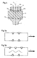
- the bone anchoring device comprises a bone anchoring element 1 in the form of a monoaxial bone screw having a shank 2 with a bone thread and a tip at one end and a receiving part 3 at the opposite end.
- the receiving part 3 is substantially cylindrically-shaped and comprises a substantially U-shaped recess 4 forming two free legs 5, 6.
- An internal thread 7 is provided on the legs.
- the bottom of the U-shaped recess forms a seat 8 for receiving a rod 9.
- the rod 9 is used to connect several bone anchoring elements.
- locking element in the form of an inner screw 10 is provided which can be screwed-in between the legs 5, 6.
- a plurality of rib-like projections 11 are provided on the surface of the seat 8.
- the rib-like projections 11 extend in a direction perpendicular to the longitudinal axis L of the recess 4 and hence extend perpendicular to the longitudinal axis L R of the rod 9.
- the projections 11 have a substantially triangular cross-section with a rounded tip.
- the projections 11 have such a length that they form a U-shape corresponding to the seat 8. They end at a distance from the internal thread 7.
- Each or several of the rib-like projections 11 may run out on one or on either side in groove-like recesses which provide depressions in the surface of the seat. Alternatively, one or several depressions in the surface of the seat which adjoins one or several of the projections can be provided.
- the rod 9 is made of an elastic flexible biocompatible material, preferably of plastics.
- the rod 9 is made of an elastomer material on the basis of polycarbonate-polyurethane or polycarbonateurethane (PCU).
- PCU polycarbonateurethane
- the inner screw 10 which is to be screwed between the legs 5, 6 comprises at its side 10a facing the rod 9 a ring shaped projection 12 in form of an annular rib with a central cavity.
- the ring-shaped projection 12 has a cross-section which is similar to the cross-section of the rib-like projections 11 of the seat.
- the diameter of the ring-shaped projection 12 is such that the contact areas 12a, 12b and the contact areas 11a and 11b of the two outer rib-like projections are located on opposite sides of the surface of the rod 9 on a vertical line Va, Vb which is parallel to the central axis C of the receiving part 3, respectively.
- the bone anchoring element 1 and the inner screw 10 are made of a biocompatible rigid material, preferably of a metal, such as titanium or a titanium alloy.
- first at least two bone anchoring elements 1 are screwed into adjacent vertebrae, for example into the pedicles of the vertebrae.
- rod 9 is inserted into the receiving parts 3 until it is seated in the seat 8.
- the rod is locked in its position by screwing-in the inner screw 10. If the inner screw 10 is not yet tightened, the position of the rod can still be adjusted in a stepless manner, since the rod has a smooth surface.
- the inner screw 10 is tightened until the ring-shaped projection 12 comes into contact with the surface of the rod. As can be seen in Fig. 4 the opposite portions 12a and 12b of the ring-shaped projection are pressed down on the surface of the rod.
- the diameter of the ring-shaped projection 12 can be equal or larger than the distance between the outmost rib-like projections 11.
- one arrangement of the engagement structure formed by the projections of the seat and the engagement structure formed by the projection on the locking element at corresponding locations on opposite surface portions of the rod provides a form-fit connection which is resistant to a force F acting in the longitudinal direction of the rod 9.
- the ring-shaped projection of the inner screw makes it possible that the engagement structure is provided at the locking element itself instead of using a filling piece or pressure piece.
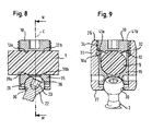
- Fig. 6 to 14 show a second embodiment of the bone anchoring device.
- the bone anchoring device comprises a bone anchoring element 20 in the form of a polyaxial bone screw having a screw element with a shank 21 with a bone thread, a tip at one end and a spherical head 22 at the opposite end.
- a recess 23 for engagement with the screwing-in tool is provided at the side of the head 22 which is opposite to the shank.
- the bone anchoring element 20 further comprises a receiving part 25 which has a first end 26 and a second end 27 opposite to the first end and a central axis C intersecting the plane of the first end and the second end. Coaxially with the central axis C a bore 29 is provided which extends from the first end to predetermined distance from the second end. At the second end 27 an opening 30 is provided the diameter of which is smaller than the diameter of the bore 29.
- the head 22 is pivotably held in the receiving part 25 with the shank extending through the opening 30.
- the receiving part 25 further has a substantially U-shaped recess 31 which starts at the first end 26 and extends in the direction of the second end 27.
- a substantially U-shaped recess 31 which starts at the first end 26 and extends in the direction of the second end 27.
- two free legs 32, 33 are formed which have an internal thread 34.
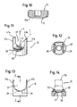
- a pressure element 35 is provided which a substantially cylindrical construction with an outer diameter which is only slightly smaller than the inner diameter of the bore 29 to allow the pressure element 35 to be introduced into the bore 29 of the receiving part and to be moved in the axial direction.
- the pressure element 35 On its lower side facing towards the second end 27 the pressure element 35 comprises a spherical recess 36 the radius of which corresponds to the radius of the spherical thread 22 of the screw element.
- On the opposite side pressure element 35 comprises a U-shaped recess 37 extending transversely to the central axis C. The lateral diameter of this recess is selected such that the rod 9 which is to be received in the receiving part 3 can be inserted into the recess 37 and guided laterally therein.
- the depth of the U-shaped recess 37 is selected such that in an assembled state when the rod is placed into the U-shaped recess 37, legs 37a, 37b of the recess extend up to the upper surface of the rod.
- the depth of the recess 37 is equal to the diameter of the rod 9.
- the lateral diameter of the recess in the area of the ribs and/or the depth of the recess 37 can be slightly larger than the diameter of the rod to allow local plastic flow of the material of the rod.
- the bottom 38 of the U-shaped recess of the pressure element 35 forms a seat for the rod 9. Similar to the first embodiment a plurality of rib-like projections 39 are provided on the surface of the seat 38. In the embodiment shown, there are two rib-like projections 39, extending in a direction transversely to the longitudinal axis I of the U-shaped recess 37 and, therefore, transversely to the longitudinal axis L R of the rod 9. Furthermore, the pressure element comprises a coaxial bore 40 to allow access to the recess 23 of the head 22 with a screwing-in tool.
- the locking element is the inner screw 10 as in the first embodiment, which has the ring-shaped projection 12 on its side 10a facing the rod 9.
- the dimensions of the ring-shaped projeciton 12 is such that, as shown in Fig. 8 , the contact areas 12a and 12b of the ring-shaped projection 12 with the rod are located at positions corresponding to the contact areas 39a, 39b of the rib-like projections of the pressure element on opposite sides of the rod.
- the dimensions of the pressure element 35 and the inner screw 10 are such that in the assembled state the lower side 10a of the inner screw rests on the upper end surface 41 a, 41 b of the legs of the pressure element.
- the dimensions of the projections 39 of the pressure element and the ring-shaped projection 12 of the inner screw are such that safe fixation by means of a press-fit with indirect form-fit is achieved without harming the integrity of the surface of the rod.
- the bone anchoring element 20 is preassembled, i.e. the bone screw is pivotably held in the receiving part and the pressure element is inserted and slightly held in a position in which its U-shaped recess is aligned with the U-shaped recess of the receiving part.
- the bone anchoring element is screwed into the bone and the angular position of the receiving part relative to the bone screw is adjusted.
- the rod 9 is inserted and the inner screw 10 tightened down until it clamps the rod.
- the function of the clamping is the same as in the first embodiment.
- the number of the rib-like projections may vary. Instead of having only rib-like projections provided at the surface of the locking element and the seat a combination of projections and depressions can be provided. Hence, this allows the material which is displaced when the projections press onto the surface of the rod to flow in the depressions to generate a form-fit connection.
- the volumes of projections and depressions are similar or have the same size such that after the flow of material is completed, the volume of the rod in a region of the connection with the receiving part has approximately the same size as before.
- the projections and/or depressions need not to have a rib- or groove-like structure but can have any shape.
- the projection which comes into contact with the surface of the rod can have another shape than a ring shape.
- at least one tooth should be provided which shaped so as to sink into the surface of the rod to create an indirect form-fit between the locking element and the rod or between the seat and the rod, respectively.
- a ring-shaped structure of the projection on the locking element is preferable, since it facilitates tightening of the locking element by means of a turning motion.
- the rod needs not to have a circular cross section. It can have an oval rectangular or square cross section.
- a cap can be provided for closing the bore after the bone anchoring element is screwed into the bone.
- the locking element can also be modified.
- the locking element can be a nut with a coaxial pin which is formed in one piece with the nut.
- the pin has the projection which comes into contact with the surface of the rod.
- the free legs of the receiving part have an external thread which cooperates with the thread of the nut.
- the bone anchoring element is introduced from the top into the receiving part.
- the bone anchoring element can also be introduces from the bottom of the receiving part if the receiving part is constructed to allow this.
- the head of the bone anchoring element and the shaft can be constructed as separate parts which can be assembled.
- the invention is not limited to screws as bone anchoring elements but can be realised with bone hooks or any other bone anchoring element.
Claims (13)
- Knochenverankerungsvorrichtung mit
einem Verankerungselement (1; 20) mit einem Schaft (2; 21), der in einem Knochen oder einem Wirbel zu verankern ist;
einem Verbindungselement (9) zum Verbinden von zumindest zwei Verankerungselementen;
einem Aufnahmeteil (3; 25), das mit dem Schaft verbunden ist, um das Verbindungselement aufzunehmen und das Verbindungselement mit dem Schaft zu verbinden;
einem Sitz (8; 38) für das Verbindungselement, wobei der Sitz in dem Aufnahmeteil vorgesehen ist;
einem einstückigen Verriegelungselement (10), das mit dem Aufnahmeteil drehbar in Eingriff gelangen kann, um das Verbindungselement in dem Sitz zu fixieren;
wobei
zumindest der Abschnitt des Verbindungselements (9), der in der Ausnehmung aufgenommen ist, eine im Wesentlichen glatte Oberfläche hat, und wobei das Verriegelungselement (10) eine Eingriffsstruktur (12) hat, die durch Vorsprünge, die mit der Oberfläche des Verbindungselements in Kontakt sind, gebildet ist, und
das Verbindungselement (9) aus einem elastischen Material besteht, das durch Drücken der Eingriffsstruktur (12) gegen das Verbindungselement (9) elastisch verformt wird;
und wobei der Sitz (8; 38) eine Eingriffsstruktur (11; 39) aufweist,
dadurch gekennzeichnet, dass
die Eingriffsstruktur des Sitzes durch Vorsprünge, die mit der Oberfläche des Verbindungselements (9) in Kontakt sind, gebildet ist; und wobei
die Vorsprünge der Eingriffsstruktur (12) des Verriegelungselements (10) und die Vorsprünge der Eingriffsstruktur (11, 39) des Sitzes (8, 38) an entsprechenden Positionen auf gegenüberliegenden Seiten des Verbindungselements angeordnet sind. - Knochenverankerungsvorrichtung gemäß Anspruch 1, wobei das Aufnahmeteil (3; 25) eine im Wesentlichen U-förmige Ausnehmung (4; 31) hat, die zwei offene Schenkel mit einem Innengewinde ausbildet, das an den Schenkeln vorgesehen ist, und wobei das Verriegelungselement (10) eine innere Schraube ist, die zwischen die Schenkel einzuschrauben ist.
- Knochenverankerungsvorrichtung gemäß Anspruch 1 oder 2, wobei die Eingriffsstrukturen Vertiefungen aufweisen.
- Knochenverankerungsvorrichtung gemäß einem der Ansprüche 1 bis 3, wobei das Aufnahmeteil (3) eine im Wesentlichen U-förmige Ausnehmung (4) hat, die zwei offene Schenkel (6, 7) ausbildet, und wobei der Sitz (8) an dem Boden der Ausnehmung vorgesehen ist.
- Knochenverankerungsvorrichtung gemäß einem der Ansprüche 1 bis 4, wobei das Knochenverankerungselement (20) mit dem Aufnahmeteil (25) schwenkbar verbunden ist, und wobei der Sitz (38) in einem Druckelement (35) vorgesehen ist, das in dem Aufnahmeteil bewegbar ist und die Winkelposition des Knochenverankerungselements verriegelt, falls Druck auf das Druckelement ausgeübt wird.
- Knochenverankerungsvorrichtung gemäß einem der Ansprüche 1 bis 5, wobei das Verbindungselement aus einem Elastomermaterial besteht.
- Knochenverankerungsvorrichtung gemäß einem der Ansprüche 1 bis 6, wobei das Verbindungselement ein Stab ist.
- Knochenverankerungsvorrichtung gemäß einem der Ansprüche 1 bis 7, wobei die Oberfläche des Verbindungselements (9) keine Vorsprünge und/oder Vertiefungen hat.
- Knochenverankerungsvorrichtung gemäß einem der Ansprüche 1 bis 8, wobei die Eingriffsstruktur des Verriegelungselements mit der Oberfläche des Verbindungselements im Eingriff ist, um eine indirekte formschlüssige Verbindung zu erzeugen.
- Knochenverankerungsvorrichtung gemäß einem der Ansprüche 1 bis 9, wobei die Eingriffsstruktur des Sitzes mit der Oberfläche des Verbindungselements im Eingriff ist, um eine indirekte formschlüssige Verbindung zu erzeugen.
- Knochenverankerungsvorrichtung gemäß einem der Ansprüche 1 bis 10, wobei das Verriegeln des Verbindungselements in dem Aufnahmeteil durch eine Reibverbindung mit einem Abschnitt einer indirekten formschlüssigen Verbindung des Verriegelungselements mit dem Verbindungselement erreicht wird.
- Knochenverankerungsvorrichtung gemäß einem der Ansprüche 1 bis 11, wobei die Verbindung zwischen dem Verriegelungselement und dem Aufnahmeteil eine Gewindeverbindung ist.
- Knochenverankerungsvorrichtung gemäß einem der Ansprüche 1 bis 12, wobei der Stab zwischen dem Sitz und dem Verriegelungselement geklemmt ist, und wobei eine Kontur des Sitzes und eine Kontur des Verriegelungselements von der Kontur des Stabs abweichen.
Priority Applications (9)
| Application Number | Priority Date | Filing Date | Title |
|---|---|---|---|
| ES06019341T ES2336815T5 (es) | 2006-09-15 | 2006-09-15 | Dispositivo de anclaje óseo |
| DE602006010556T DE602006010556D1 (de) | 2006-09-15 | 2006-09-15 | Knochenverankerungsvorrichtung |
| EP06019341A EP1900334B2 (de) | 2006-09-15 | 2006-09-15 | Knochenverankerungsvorrichtung |
| KR20070092646A KR101486978B1 (ko) | 2006-09-15 | 2007-09-12 | 뼈 고정장치 |
| JP2007236712A JP5361161B2 (ja) | 2006-09-15 | 2007-09-12 | 骨固定装置 |
| CN2007101489373A CN101143108B (zh) | 2006-09-15 | 2007-09-12 | 骨锚固装置 |
| TW096133972A TWI413505B (zh) | 2006-09-15 | 2007-09-12 | 骨骼固定裝置 |
| US11/854,508 US8568458B2 (en) | 2006-09-15 | 2007-09-12 | Bone anchoring device |
| US13/613,739 US20130066381A1 (en) | 2006-09-15 | 2012-09-13 | Bone anchoring device |
Applications Claiming Priority (1)
| Application Number | Priority Date | Filing Date | Title |
|---|---|---|---|
| EP06019341A EP1900334B2 (de) | 2006-09-15 | 2006-09-15 | Knochenverankerungsvorrichtung |
Publications (3)
| Publication Number | Publication Date |
|---|---|
| EP1900334A1 EP1900334A1 (de) | 2008-03-19 |
| EP1900334B1 EP1900334B1 (de) | 2009-11-18 |
| EP1900334B2 true EP1900334B2 (de) | 2013-01-16 |
Family
ID=37695933
Family Applications (1)
| Application Number | Title | Priority Date | Filing Date |
|---|---|---|---|
| EP06019341A Not-in-force EP1900334B2 (de) | 2006-09-15 | 2006-09-15 | Knochenverankerungsvorrichtung |
Country Status (7)
| Country | Link |
|---|---|
| US (2) | US8568458B2 (de) |
| EP (1) | EP1900334B2 (de) |
| JP (1) | JP5361161B2 (de) |
| CN (1) | CN101143108B (de) |
| DE (1) | DE602006010556D1 (de) |
| ES (1) | ES2336815T5 (de) |
| TW (1) | TWI413505B (de) |
Families Citing this family (34)
| Publication number | Priority date | Publication date | Assignee | Title |
|---|---|---|---|---|
| US8366753B2 (en) | 2003-06-18 | 2013-02-05 | Jackson Roger P | Polyaxial bone screw assembly with fixed retaining structure |
| US7967850B2 (en) | 2003-06-18 | 2011-06-28 | Jackson Roger P | Polyaxial bone anchor with helical capture connection, insert and dual locking assembly |
| US7776067B2 (en) | 2005-05-27 | 2010-08-17 | Jackson Roger P | Polyaxial bone screw with shank articulation pressure insert and method |
| US8936623B2 (en) | 2003-06-18 | 2015-01-20 | Roger P. Jackson | Polyaxial bone screw assembly |
| US8444681B2 (en) | 2009-06-15 | 2013-05-21 | Roger P. Jackson | Polyaxial bone anchor with pop-on shank, friction fit retainer and winged insert |
| CH705709B1 (de) * | 2005-08-29 | 2013-05-15 | Bird Biedermann Ag | Wirbelsäulenimplantat. |
| DE502006002049D1 (de) * | 2005-09-13 | 2008-12-24 | Bird Biedermann Ag | Dynamische Klemmvorrichtung für Wirbelsäulenimplantat |
| GB0521582D0 (en) * | 2005-10-22 | 2005-11-30 | Depuy Int Ltd | An implant for supporting a spinal column |
| GB0521585D0 (en) * | 2005-10-22 | 2005-11-30 | Depuy Int Ltd | A spinal support rod |
| EP1795134B1 (de) * | 2005-11-17 | 2008-08-06 | BIEDERMANN MOTECH GmbH | Polyaxialschraube für flexiblen Stab |
| GB0600662D0 (en) * | 2006-01-13 | 2006-02-22 | Depuy Int Ltd | Spinal support rod kit |
| US8348952B2 (en) | 2006-01-26 | 2013-01-08 | Depuy International Ltd. | System and method for cooling a spinal correction device comprising a shape memory material for corrective spinal surgery |
| DE502006004368D1 (de) * | 2006-02-03 | 2009-09-10 | Spinelab Ag | Wirbelsäulenimplantat |
| ES2421707T3 (es) * | 2007-02-23 | 2013-09-05 | Biedermann Technologies Gmbh | Conector de varilla para estabilizar vértebras |
| DE602007007466D1 (de) * | 2007-07-20 | 2010-08-12 | Biedermann Motech Gmbh | Knochenverankerungsvorrichtung |
| GB0720762D0 (en) | 2007-10-24 | 2007-12-05 | Depuy Spine Sorl | Assembly for orthopaedic surgery |
| EP2105101B2 (de) * | 2008-03-28 | 2013-09-11 | BIEDERMANN MOTECH GmbH | Knochenverankerungsvorrichtung |
| WO2009124196A2 (en) * | 2008-04-03 | 2009-10-08 | Life Spine, Inc. | Top loading polyaxial spine screw assembly with one step lockup |
| US20090264931A1 (en) * | 2008-04-18 | 2009-10-22 | Warsaw Orthopedic, Inc. | Implantable Article for Use with an Anchor and a Non-Metal Rod |
| ES2375526T3 (es) * | 2008-06-19 | 2012-03-01 | Biedermann Motech Gmbh | Conjunto de anclaje óseo. |
| AU2010260521C1 (en) | 2008-08-01 | 2013-08-01 | Roger P. Jackson | Longitudinal connecting member with sleeved tensioned cords |
| EP2160988B1 (de) | 2008-09-04 | 2012-12-26 | Biedermann Technologies GmbH & Co. KG | Stangenförmiges Implantat, insbesondere zur Stabilisierung der Wirbelsäule, und Stabilisierungsvorrichtung mit einem derartigen stangenförmigen Implantat |
| IT1394182B1 (it) * | 2009-05-07 | 2012-06-01 | Nardi | Gruppo di accoppiamento, particolarmente per impianti dentali |
| US8998959B2 (en) | 2009-06-15 | 2015-04-07 | Roger P Jackson | Polyaxial bone anchors with pop-on shank, fully constrained friction fit retainer and lock and release insert |
| CN103826560A (zh) | 2009-06-15 | 2014-05-28 | 罗杰.P.杰克逊 | 具有套接杆和带摩擦配合压缩套爪的带翼插件的多轴骨锚 |
| CN103917181A (zh) | 2009-06-15 | 2014-07-09 | 罗杰.P.杰克逊 | 包括套接杆和具有低外形边缘锁的摩擦配合保持件的多轴骨锚 |
| US20110029018A1 (en) * | 2009-07-30 | 2011-02-03 | Warsaw Othropedic, Inc | Variable resistance spinal stablization systems and methods |
| KR101056120B1 (ko) | 2011-01-14 | 2011-08-11 | (주)비엠코리아 | 로드 고정 나사 및 이를 이용한 척추 고정 장치 |
| EP2559389B1 (de) * | 2011-08-18 | 2013-04-03 | Biedermann Technologies GmbH & Co. KG | Polyaxiale Knochenverankerungsvorrichtung |
| EP2574296B1 (de) | 2011-09-28 | 2016-03-02 | Biedermann Technologies GmbH & Co. KG | Knochenverankerungsanordnung |
| US9295488B2 (en) | 2012-08-09 | 2016-03-29 | Wilson T. Asfora | Joint fusion |
| CN104958100A (zh) * | 2015-05-25 | 2015-10-07 | 创生医疗器械(中国)有限公司 | 一种椎弓根螺钉用防旋顶丝 |
| EP3287089B1 (de) | 2016-08-24 | 2019-07-24 | Biedermann Technologies GmbH & Co. KG | Vorrichtung zur polyaxialen knochenverankerung und system eines instruments und eine vorrichtung zur polyaxialen knochenverankerung |
| US20200390472A1 (en) * | 2019-02-27 | 2020-12-17 | Orthopediatrics Corp. | Bone anchor with cord retention features |
Citations (1)
| Publication number | Priority date | Publication date | Assignee | Title |
|---|---|---|---|---|
| US20040172025A1 (en) † | 2001-10-30 | 2004-09-02 | Drewry Troy D. | Flexible spinal stabilization system and method |
Family Cites Families (31)
| Publication number | Priority date | Publication date | Assignee | Title |
|---|---|---|---|---|
| US4743260A (en) * | 1985-06-10 | 1988-05-10 | Burton Charles V | Method for a flexible stabilization system for a vertebral column |
| FR2633177B1 (fr) * | 1988-06-24 | 1991-03-08 | Fabrication Materiel Orthopedi | Implant pour dispositif d'osteosynthese rachidienne, notamment en traumatologie |
| WO1991016020A1 (en) * | 1990-04-26 | 1991-10-31 | Danninger Medical Technology, Inc. | Transpedicular screw system and method of use |
| CH681853A5 (de) * | 1990-08-21 | 1993-06-15 | Synthes Ag | |
| FR2676911B1 (fr) * | 1991-05-30 | 1998-03-06 | Psi Ste Civile Particuliere | Dispositif de stabilisation intervertebrale a amortisseurs. |
| US5257993A (en) * | 1991-10-04 | 1993-11-02 | Acromed Corporation | Top-entry rod retainer |
| EP0572790B1 (de) * | 1992-06-04 | 1996-02-14 | Synthes AG, Chur | Osteosynthetisches Befestigungselement |
| US6077262A (en) * | 1993-06-04 | 2000-06-20 | Synthes (U.S.A.) | Posterior spinal implant |
| ATE196983T1 (de) * | 1994-06-30 | 2000-11-15 | Sulzer Orthopaedie Ag | Vorrichtung zum verbinden von wirbelknochen |
| US5591235A (en) | 1995-03-15 | 1997-01-07 | Kuslich; Stephen D. | Spinal fixation device |
| US6749361B2 (en) * | 1997-10-06 | 2004-06-15 | Werner Hermann | Shackle element for clamping a fixation rod, a method for making a shackle element, a hook with a shackle element and a rode connector with a shackle element |
| DE19818765A1 (de) * | 1998-04-07 | 1999-10-14 | Schaefer Micomed Gmbh | Osteosynthesevorrichtung |
| US6565565B1 (en) * | 1998-06-17 | 2003-05-20 | Howmedica Osteonics Corp. | Device for securing spinal rods |
| US6224598B1 (en) | 2000-02-16 | 2001-05-01 | Roger P. Jackson | Bone screw threaded plug closure with central set screw |
| KR200200582Y1 (ko) * | 2000-03-15 | 2000-10-16 | 최길운 | 접골용 보철구 |
| JP2002320622A (ja) | 2001-04-26 | 2002-11-05 | Kyocera Corp | 脊椎骨矯正固定装置 |
| US6478797B1 (en) * | 2001-05-16 | 2002-11-12 | Kamaljit S. Paul | Spinal fixation device |
| US6793657B2 (en) * | 2001-09-10 | 2004-09-21 | Solco Biomedical Co., Ltd. | Spine fixing apparatus |
| US6652526B1 (en) | 2001-10-05 | 2003-11-25 | Ruben P. Arafiles | Spinal stabilization rod fastener |
| US6966910B2 (en) * | 2002-04-05 | 2005-11-22 | Stephen Ritland | Dynamic fixation device and method of use |
| EP1364622B1 (de) * | 2002-05-21 | 2005-07-20 | Spinelab GmbH | Elastisches Stabilisiersystem für Wirbelsäulen |
| US6730089B2 (en) * | 2002-08-26 | 2004-05-04 | Roger P. Jackson | Nested closure plug and set screw with break-off heads |
| US6843791B2 (en) * | 2003-01-10 | 2005-01-18 | Depuy Acromed, Inc. | Locking cap assembly for spinal fixation instrumentation |
| EP1527742B1 (de) | 2003-10-31 | 2006-07-26 | Spinelab AG | Verschlussvorrichtung für Pedikelschrauben zur Fixierung von elastischen Stabelementen |
| TW200518711A (en) * | 2003-12-11 | 2005-06-16 | A Spine Holding Group Corp | Rotation buckling ball-head spine restoring equipment |
| JP4714733B2 (ja) * | 2004-03-04 | 2011-06-29 | ジンテーズ ゲゼルシャフト ミト ベシュレンクテル ハフツング | 骨結合素子のための結合棒 |
| DE102004010844A1 (de) | 2004-03-05 | 2005-10-06 | Biedermann Motech Gmbh | Stabilisierungseinrichtung zur dynamischen Stabilisierung von Wirbeln oder Knochen und stabförmiges Element für eine derartige Stabilisierungseinrichtung |
| US7857834B2 (en) | 2004-06-14 | 2010-12-28 | Zimmer Spine, Inc. | Spinal implant fixation assembly |
| CH705709B1 (de) * | 2005-08-29 | 2013-05-15 | Bird Biedermann Ag | Wirbelsäulenimplantat. |
| DE502006002049D1 (de) * | 2005-09-13 | 2008-12-24 | Bird Biedermann Ag | Dynamische Klemmvorrichtung für Wirbelsäulenimplantat |
| EP1795134B1 (de) * | 2005-11-17 | 2008-08-06 | BIEDERMANN MOTECH GmbH | Polyaxialschraube für flexiblen Stab |
-
2006
- 2006-09-15 ES ES06019341T patent/ES2336815T5/es active Active
- 2006-09-15 DE DE602006010556T patent/DE602006010556D1/de active Active
- 2006-09-15 EP EP06019341A patent/EP1900334B2/de not_active Not-in-force
-
2007
- 2007-09-12 JP JP2007236712A patent/JP5361161B2/ja not_active Expired - Fee Related
- 2007-09-12 TW TW096133972A patent/TWI413505B/zh not_active IP Right Cessation
- 2007-09-12 CN CN2007101489373A patent/CN101143108B/zh not_active Expired - Fee Related
- 2007-09-12 US US11/854,508 patent/US8568458B2/en not_active Expired - Fee Related
-
2012
- 2012-09-13 US US13/613,739 patent/US20130066381A1/en not_active Abandoned
Patent Citations (1)
| Publication number | Priority date | Publication date | Assignee | Title |
|---|---|---|---|---|
| US20040172025A1 (en) † | 2001-10-30 | 2004-09-02 | Drewry Troy D. | Flexible spinal stabilization system and method |
Non-Patent Citations (1)
| Title |
|---|
| DR.-ING. RISCHARD ERNST: "Wörterbuch der Industriellen Technik", pages: 281 † |
Also Published As
| Publication number | Publication date |
|---|---|
| JP5361161B2 (ja) | 2013-12-04 |
| CN101143108A (zh) | 2008-03-19 |
| ES2336815T5 (es) | 2013-05-16 |
| TW200812542A (en) | 2008-03-16 |
| ES2336815T3 (es) | 2010-04-16 |
| EP1900334A1 (de) | 2008-03-19 |
| TWI413505B (zh) | 2013-11-01 |
| US20130066381A1 (en) | 2013-03-14 |
| US8568458B2 (en) | 2013-10-29 |
| DE602006010556D1 (de) | 2009-12-31 |
| EP1900334B1 (de) | 2009-11-18 |
| JP2008068091A (ja) | 2008-03-27 |
| US20080114404A1 (en) | 2008-05-15 |
| CN101143108B (zh) | 2012-07-04 |
Similar Documents
| Publication | Publication Date | Title |
|---|---|---|
| EP1900334B2 (de) | Knochenverankerungsvorrichtung | |
| EP2135573B1 (de) | Knochenverankerungsvorrichtung | |
| US7731749B2 (en) | Bone anchoring device | |
| EP1891904B1 (de) | Knochenverankerungsvorrichtung | |
| EP1842503B1 (de) | Abgewinkelte polyaxiale Knochenverankerungsvorrichtung | |
| EP1743584B1 (de) | Knochenverankerungsvorrichtung | |
| EP1839606B1 (de) | Verriegelungsaufbau zur Sicherung eines Stabelements in einem Aufnahmeteil zur Verwendung in der Wirbensäulenchirurgie oder Traumatologie, Knochenverankerungsvorrichtung mit einem solchen Verriegelungsaufbau und Werkzeug dafür | |
| EP2335625B1 (de) | Knochenverankerungsvorrichtung | |
| EP1935358B1 (de) | Knochenverankerungsvorrichtung | |
| US20060271193A1 (en) | Device for connecting a longitudinal member to a bone | |
| KR101486978B1 (ko) | 뼈 고정장치 | |
| KR101507574B1 (ko) | 뼈 고정장치 |
Legal Events
| Date | Code | Title | Description |
|---|---|---|---|
| PUAI | Public reference made under article 153(3) epc to a published international application that has entered the european phase |
Free format text: ORIGINAL CODE: 0009012 |
|
| AK | Designated contracting states |
Kind code of ref document: A1 Designated state(s): CH DE ES FR GB IT LI |
|
| AX | Request for extension of the european patent |
Extension state: AL BA HR MK YU |
|
| 17P | Request for examination filed |
Effective date: 20080328 |
|
| 17Q | First examination report despatched |
Effective date: 20080430 |
|
| AKX | Designation fees paid |
Designated state(s): CH DE ES FR GB IT LI |
|
| GRAP | Despatch of communication of intention to grant a patent |
Free format text: ORIGINAL CODE: EPIDOSNIGR1 |
|
| GRAS | Grant fee paid |
Free format text: ORIGINAL CODE: EPIDOSNIGR3 |
|
| GRAA | (expected) grant |
Free format text: ORIGINAL CODE: 0009210 |
|
| AK | Designated contracting states |
Kind code of ref document: B1 Designated state(s): CH DE ES FR GB IT LI |
|
| REG | Reference to a national code |
Ref country code: GB Ref legal event code: FG4D |
|
| REG | Reference to a national code |
Ref country code: CH Ref legal event code: EP |
|
| REG | Reference to a national code |
Ref country code: CH Ref legal event code: NV Representative=s name: NOVAGRAAF INTERNATIONAL SA |
|
| REF | Corresponds to: |
Ref document number: 602006010556 Country of ref document: DE Date of ref document: 20091231 Kind code of ref document: P |
|
| REG | Reference to a national code |
Ref country code: ES Ref legal event code: FG2A Ref document number: 2336815 Country of ref document: ES Kind code of ref document: T3 |
|
| PLBI | Opposition filed |
Free format text: ORIGINAL CODE: 0009260 |
|
| PLAB | Opposition data, opponent's data or that of the opponent's representative modified |
Free format text: ORIGINAL CODE: 0009299OPPO |
|
| PLAX | Notice of opposition and request to file observation + time limit sent |
Free format text: ORIGINAL CODE: EPIDOSNOBS2 |
|
| 26 | Opposition filed |
Opponent name: SPINELAB AG Effective date: 20100816 |
|
| R26 | Opposition filed (corrected) |
Opponent name: SPINELAB AG Effective date: 20100816 |
|
| PLAF | Information modified related to communication of a notice of opposition and request to file observations + time limit |
Free format text: ORIGINAL CODE: EPIDOSCOBS2 |
|
| PLBB | Reply of patent proprietor to notice(s) of opposition received |
Free format text: ORIGINAL CODE: EPIDOSNOBS3 |
|
| REG | Reference to a national code |
Ref country code: CH Ref legal event code: PFA Owner name: BIEDERMANN MOTECH GMBH Free format text: BIEDERMANN MOTECH GMBH#BERTHA-VON-SUTTNER-STRASSE 23#78054 VS-SCHWENNINGEN (DE) -TRANSFER TO- BIEDERMANN MOTECH GMBH#BERTHA-VON-SUTTNER-STRASSE 23#78054 VS-SCHWENNINGEN (DE) |
|
| REG | Reference to a national code |
Ref country code: DE Ref legal event code: R082 Ref document number: 602006010556 Country of ref document: DE Representative=s name: PRUEFER & PARTNER GBR, DE |
|
| PUAH | Patent maintained in amended form |
Free format text: ORIGINAL CODE: 0009272 |
|
| STAA | Information on the status of an ep patent application or granted ep patent |
Free format text: STATUS: PATENT MAINTAINED AS AMENDED |
|
| 27A | Patent maintained in amended form |
Effective date: 20130116 |
|
| AK | Designated contracting states |
Kind code of ref document: B2 Designated state(s): CH DE ES FR GB IT LI |
|
| REG | Reference to a national code |
Ref country code: DE Ref legal event code: R102 Ref document number: 602006010556 Country of ref document: DE |
|
| REG | Reference to a national code |
Ref country code: DE Ref legal event code: R082 Ref document number: 602006010556 Country of ref document: DE Representative=s name: PRUEFER & PARTNER GBR, DE Effective date: 20121128 Ref country code: DE Ref legal event code: R081 Ref document number: 602006010556 Country of ref document: DE Owner name: BIEDERMANN TECHNOLOGIES GMBH & CO. KG, DE Free format text: FORMER OWNER: BIEDERMANN MOTECH GMBH, 78054 VILLINGEN-SCHWENNINGEN, DE Effective date: 20121128 Ref country code: DE Ref legal event code: R082 Ref document number: 602006010556 Country of ref document: DE Representative=s name: PRUEFER & PARTNER MBB PATENTANWAELTE RECHTSANW, DE Effective date: 20121128 |
|
| REG | Reference to a national code |
Ref country code: CH Ref legal event code: PUE Owner name: BIEDERMANN TECHNOLOGIES GMBH AND CO. KG, DE Free format text: FORMER OWNER: BIEDERMANN MOTECH GMBH AND CO. KG, DE Ref country code: CH Ref legal event code: PFA Owner name: BIEDERMANN MOTECH GMBH AND CO. KG, DE Free format text: FORMER OWNER: BIEDERMANN MOTECH GMBH, DE Ref country code: CH Ref legal event code: AELC |
|
| REG | Reference to a national code |
Ref country code: CH Ref legal event code: PFA Owner name: BIEDERMANN MOTECH GMBH AND CO. KG, DE Free format text: FORMER OWNER: BIEDERMANN MOTECH GMBH, DE Ref country code: ES Ref legal event code: PC2A Owner name: BIEDERMANN MOTECH GMBH & CO.KG. Effective date: 20130205 Ref country code: CH Ref legal event code: AELC Ref country code: CH Ref legal event code: PUE Owner name: BIEDERMANN TECHNOLOGIES GMBH AND CO. KG, DE Free format text: FORMER OWNER: BIEDERMANN MOTECH GMBH AND CO. KG, DE |
|
| REG | Reference to a national code |
Ref country code: DE Ref legal event code: R102 Ref document number: 602006010556 Country of ref document: DE Effective date: 20130116 |
|
| REG | Reference to a national code |
Ref country code: ES Ref legal event code: PC2A Owner name: BIEDERMANN TECHNOLOGIES GMBH & CO. KG Effective date: 20130311 |
|
| REG | Reference to a national code |
Ref country code: GB Ref legal event code: 732E Free format text: REGISTERED BETWEEN 20130307 AND 20130313 |
|
| REG | Reference to a national code |
Ref country code: FR Ref legal event code: CD Owner name: BIEDERMANN TECHNOLOGIES GMBH & CO.KG, DE Effective date: 20130329 Ref country code: FR Ref legal event code: TP Owner name: BIEDERMANN TECHNOLOGIES GMBH & CO.KG, DE Effective date: 20130329 |
|
| REG | Reference to a national code |
Ref country code: ES Ref legal event code: DC2A Ref document number: 2336815 Country of ref document: ES Kind code of ref document: T5 Effective date: 20130516 |
|
| REG | Reference to a national code |
Ref country code: FR Ref legal event code: PLFP Year of fee payment: 10 |
|
| PGFP | Annual fee paid to national office [announced via postgrant information from national office to epo] |
Ref country code: GB Payment date: 20150922 Year of fee payment: 10 Ref country code: CH Payment date: 20150922 Year of fee payment: 10 Ref country code: ES Payment date: 20150923 Year of fee payment: 10 |
|
| PGFP | Annual fee paid to national office [announced via postgrant information from national office to epo] |
Ref country code: FR Payment date: 20150923 Year of fee payment: 10 |
|
| PGFP | Annual fee paid to national office [announced via postgrant information from national office to epo] |
Ref country code: IT Payment date: 20150925 Year of fee payment: 10 Ref country code: DE Payment date: 20150929 Year of fee payment: 10 |
|
| REG | Reference to a national code |
Ref country code: DE Ref legal event code: R119 Ref document number: 602006010556 Country of ref document: DE |
|
| REG | Reference to a national code |
Ref country code: CH Ref legal event code: PL |
|
| GBPC | Gb: european patent ceased through non-payment of renewal fee |
Effective date: 20160915 |
|
| REG | Reference to a national code |
Ref country code: FR Ref legal event code: ST Effective date: 20170531 |
|
| PG25 | Lapsed in a contracting state [announced via postgrant information from national office to epo] |
Ref country code: CH Free format text: LAPSE BECAUSE OF NON-PAYMENT OF DUE FEES Effective date: 20160930 Ref country code: GB Free format text: LAPSE BECAUSE OF NON-PAYMENT OF DUE FEES Effective date: 20160915 Ref country code: LI Free format text: LAPSE BECAUSE OF NON-PAYMENT OF DUE FEES Effective date: 20160930 Ref country code: DE Free format text: LAPSE BECAUSE OF NON-PAYMENT OF DUE FEES Effective date: 20170401 Ref country code: FR Free format text: LAPSE BECAUSE OF NON-PAYMENT OF DUE FEES Effective date: 20160930 |
|
| PG25 | Lapsed in a contracting state [announced via postgrant information from national office to epo] |
Ref country code: IT Free format text: LAPSE BECAUSE OF NON-PAYMENT OF DUE FEES Effective date: 20160915 |
|
| PG25 | Lapsed in a contracting state [announced via postgrant information from national office to epo] |
Ref country code: ES Free format text: LAPSE BECAUSE OF NON-PAYMENT OF DUE FEES Effective date: 20160916 |
|
| REG | Reference to a national code |
Ref country code: ES Ref legal event code: FD2A Effective date: 20181129 |