EP1899704B1 - Apparatus and methods for storing sensitive materials - Google Patents
Apparatus and methods for storing sensitive materials Download PDFInfo
- Publication number
- EP1899704B1 EP1899704B1 EP06704225A EP06704225A EP1899704B1 EP 1899704 B1 EP1899704 B1 EP 1899704B1 EP 06704225 A EP06704225 A EP 06704225A EP 06704225 A EP06704225 A EP 06704225A EP 1899704 B1 EP1899704 B1 EP 1899704B1
- Authority
- EP
- European Patent Office
- Prior art keywords
- container
- gas
- exhaust
- purge gas
- containers
- Prior art date
- Legal status (The legal status is an assumption and is not a legal conclusion. Google has not performed a legal analysis and makes no representation as to the accuracy of the status listed.)
- Expired - Lifetime
Links
Images


Classifications
-
- G—PHYSICS
- G01—MEASURING; TESTING
- G01N—INVESTIGATING OR ANALYSING MATERIALS BY DETERMINING THEIR CHEMICAL OR PHYSICAL PROPERTIES
- G01N1/00—Sampling; Preparing specimens for investigation
- G01N1/02—Devices for withdrawing samples
- G01N1/22—Devices for withdrawing samples in the gaseous state
- G01N1/2226—Sampling from a closed space, e.g. food package, head space
-
- B—PERFORMING OPERATIONS; TRANSPORTING
- B65—CONVEYING; PACKING; STORING; HANDLING THIN OR FILAMENTARY MATERIAL
- B65B—MACHINES, APPARATUS OR DEVICES FOR, OR METHODS OF, PACKAGING ARTICLES OR MATERIALS; UNPACKING
- B65B31/00—Packaging articles or materials under special atmospheric or gaseous conditions; Adding propellants to aerosol containers
- B65B31/04—Evacuating, pressurising or gasifying filled containers or wrappers by means of nozzles through which air or other gas, e.g. an inert gas, is withdrawn or supplied
-
- B—PERFORMING OPERATIONS; TRANSPORTING
- B65—CONVEYING; PACKING; STORING; HANDLING THIN OR FILAMENTARY MATERIAL
- B65D—CONTAINERS FOR STORAGE OR TRANSPORT OF ARTICLES OR MATERIALS, e.g. BAGS, BARRELS, BOTTLES, BOXES, CANS, CARTONS, CRATES, DRUMS, JARS, TANKS, HOPPERS, FORWARDING CONTAINERS; ACCESSORIES, CLOSURES, OR FITTINGS THEREFOR; PACKAGING ELEMENTS; PACKAGES
- B65D81/00—Containers, packaging elements, or packages, for contents presenting particular transport or storage problems, or adapted to be used for non-packaging purposes after removal of contents
- B65D81/18—Containers, packaging elements, or packages, for contents presenting particular transport or storage problems, or adapted to be used for non-packaging purposes after removal of contents providing specific environment for contents, e.g. temperature above or below ambient
- B65D81/20—Containers, packaging elements, or packages, for contents presenting particular transport or storage problems, or adapted to be used for non-packaging purposes after removal of contents providing specific environment for contents, e.g. temperature above or below ambient under vacuum or superatmospheric pressure, or in a special atmosphere, e.g. of inert gas
- B65D81/2069—Containers, packaging elements, or packages, for contents presenting particular transport or storage problems, or adapted to be used for non-packaging purposes after removal of contents providing specific environment for contents, e.g. temperature above or below ambient under vacuum or superatmospheric pressure, or in a special atmosphere, e.g. of inert gas in a special atmosphere
- B65D81/2076—Containers, packaging elements, or packages, for contents presenting particular transport or storage problems, or adapted to be used for non-packaging purposes after removal of contents providing specific environment for contents, e.g. temperature above or below ambient under vacuum or superatmospheric pressure, or in a special atmosphere, e.g. of inert gas in a special atmosphere in an at least partially rigid container
-
- F—MECHANICAL ENGINEERING; LIGHTING; HEATING; WEAPONS; BLASTING
- F16—ENGINEERING ELEMENTS AND UNITS; GENERAL MEASURES FOR PRODUCING AND MAINTAINING EFFECTIVE FUNCTIONING OF MACHINES OR INSTALLATIONS; THERMAL INSULATION IN GENERAL
- F16J—PISTONS; CYLINDERS; SEALINGS
- F16J12/00—Pressure vessels in general
-
- G—PHYSICS
- G01—MEASURING; TESTING
- G01N—INVESTIGATING OR ANALYSING MATERIALS BY DETERMINING THEIR CHEMICAL OR PHYSICAL PROPERTIES
- G01N1/00—Sampling; Preparing specimens for investigation
- G01N1/02—Devices for withdrawing samples
- G01N1/22—Devices for withdrawing samples in the gaseous state
- G01N1/2226—Sampling from a closed space, e.g. food package, head space
- G01N2001/2241—Sampling from a closed space, e.g. food package, head space purpose-built sampling enclosure for emissions
Definitions
- This application relates to apparatus and methods for storing sensitive materials.
- it relates to systems in which sensitive materials are stored in a plurality of containers, each of which may constitute a sealed enclosure preventing the exchange of physical material between the external surroundings of the container, normally the ambient atmosphere, and the contents of the container.
- the contents are the sensitive material itself together with an appropriate atmosphere.
- the container may also include, for example, means for supporting the sensitive material itself.
- US-A- 5855272 discloses a system of storing sensitive materials, in this particular case audio or audio-visual recordings, by placing them in an hermetically sealable container and purging the interior of the container with an inert gas such as nitrogen or argon. Following such purging the lid of the container may be finally closed to seal it and extra purge gas injected to render the pressure of the atmosphere in the interior of the container positive with respect to ambient, thus ensuring that any leakage, at least initially, transfers material from the inside of the container to the outside rather than letting anything from the outside in.
- an inert gas such as nitrogen or argon
- US-A-5561915 discloses a container with an inbuilt carbon dioxide cartridge chamber. After the container is sealed, a cartridge is inserted into the chamber and acts to inject carbon dioxide into the interior, displacing the atmosphere therein which is exhausted via an exhaust orifice. After the atmosphere inside the container has been replaced with carbon dioxide, the spent cartridge is disposed of and the exhaust orifice sealed with a pipe plug.
- US-A-5960708 discloses stackable shipping containers consisting of a container having upper and lower members hermetically sealed together and with inlet and outlet valves to enable the interior of the container to be provided with gases to retard spoilage of food products within the container.
- US-A-5794408 discloses a method of inerting packaging covers, i.e. large flexible bags which surround items such as military equipment or packed for transportation.
- the covers are wholly sealed round the items save for two apertures, one for injecting inert gas into the bag, the other for extracting atmosphere from the bag, while always maintaining a virtual balance between the pressure inside the bag and the external ambient pressure.
- the present invention generally provides a system for the storage of sensitive materials as defined by claim 1, and a method for preserving sensitive materials as defined by claim 6.
- the apparatus may include a gas analysis or detection system to monitor the content of the exhaust gas, for example an oxygen sensor to detect the oxygen concentration in that gas, or a moisture content sensor.
- a gas analysis or detection system to monitor the content of the exhaust gas, for example an oxygen sensor to detect the oxygen concentration in that gas, or a moisture content sensor.
- the apparatus preferably includes means to inject sufficient purge gas into the container to leave the container pressurised to assist in offsetting the adverse effect of any leakage of the seal.
- the degree to which it is pressurised may be chosen as desired, but is usually relatively small, particularly since if the pressure inside the sealed container is substantial relative to ambient pressure, there is not only a risk of the seal failing but additionally the sides of the container may bulge, so preventing clean stacking of a number of containers in a suitable storage facility.
- a preferred way of achieving the desired excess pressure in the container is to configure the purging apparatus so that after the purge gas has been injected sufficiently long for the exhaust gas to reach the acceptable condition, the pressure in the container is allowed to drop by venting gas from the interior of the container while measuring the pressure, and ceasing to vent gas once the desired excess pressure level is reached.
- the purge gas outlet from the gassing apparatus may be distributed via a manifold to a plurality of inlets on a plurality of containers essentially arranged in parallel, the exhaust ports for each of the containers being likewise connected to a manifold which then connects to the inlet port on the gassing apparatus.
- the exact nature of the individual containers for sensitive products may vary widely, the fundamental requirements however being that the interior of the container may be sealed against the outside and that the container has an inlet port and outlet port. Within these constraints, the container may vary widely. It is convenient for many practical industrial applications to produce the containers in a number of standard sizes and the gassing apparatus may include a simple control to adjust the parameters such as gassing time, over-pressure and the like in accordance with the type and size of container in question.
- a preferred mode of construction of the containers is that of an open-topped box with a lid, the walls of the box and the material of the lid being of gas-impermeable material, for example sheet metal.
- sealing means need to be provided to enable the lid to be sealed to the edges of the open-topped box.
- This may be, for example, a resilient rubber or rubber-like material seal around the inside angled corner of a generally tray-shaped lid, and means may be provided on the open-topped box to enable the lid to be firmly held against the top of the open-topped box to seal its interior against the ambient atmosphere.
- the upper edges of the walls of the box may carry an annular seal strip of U-shaped cross section and made of an appropriate resilient sealing material.
- the inlet and outlet ports may be mounted on the walls of the box in customary sealed fashion. Preferably both ports are simple one-way or check valves.
- the exhaust port has an exhaust valve which opens only when the pressure within the container is above a preset level, the operation of purging the atmosphere from the interior of the container and then pressurising it may be rendered very straightforward.
- the interior of the containers may be provided if desired with any convenient fittings to assist the storage operation envisaged.
- the interior may be divided into a number of compartments, for example six compartments in a 3 x 2 array, into each of which a standard unit may be inserted.
- a standard unit for example, in handling biological samples, standard size so-called plate or tube racks are widely used and the storage container may be sized and shaped to enable an array of such racks to be easily accommodated.
- the inlet and outlet ports are standard pneumatic ports adapted for cooperating by a quick fit/quick release action with an appropriate fitting on the end of a tube such as a pressure line or exhaust line.
- the purge gas used in practising the present invention is conventionally nitrogen because it is inexpensive and effective though, for certain high specification areas, argon may be used. There is, of course, no reason not to use any other appropriate inert purge gas.
- the gassing apparatus may be constructed according to appropriate principles of engineering design and to suit the particular sensitive material storage problem envisaged. It will need to be provided with some form of power supply to operate and, of course, with a supply of purge gas, conveniently from a standard gas storage cylinder which may be connected to the gassing apparatus using conventional pressurised leads.
- Figure 1 shows a container for use in practising the invention. It consists of a metal base section 1 and a metal lid 2 in the form of a plate having a depending skirt which is adapted to fit closely around the upper edge of the side wall of the base section 1. Mounted on the side of base section 1 are four standard clips 5, each of which has a portion adapted to engage over a tab 6 located on the skirt of lid 2 and thereby urge lid 2 down towards base section 1.
- FIG. 1 An internal annular seal which runs round the inside of lid 2 and which is of an appropriate resilient material such as a rubber or silicone compound. It is in the form of an even thickness bead into which the top edge of the side walls of base section 1 is urged as the clips 5 pull the lid downwards via tabs 6.
- Two carrying handles 8 are mounted on opposite sides of the skirt forming part of lid 2 so that once the base section 1 and the lid 2 are assembled and clipped together, the entire assembly can be lifted by handles 8.
- the interior of the base has a set of dividing walls 10 which may be a preformed structure which is a relatively loose fit in the base, and which divides the space within the base section 1 into six compartments, each of which may receive a standard size sample array 12.
- Mounted on one wall of the base 1 is an inlet port 14 of conventional pneumatic construction.
- An exhaust port (not shown in Figure 1 ) is mounted on the opposite wall to port 14.
- Figure 2 shows a typical arrangement of a system in accordance with the present invention.
- a purge gas unit generally denoted 30 the on the left a container of the type shown in figure 1 and generally denoted 32.
- unit 30 consists of a generally rectangular casing having outlet and inlet ports 33 and 34 mounted on its front face.
- a pneumatic line 35 is connected between the outlet port 33 of the purge gas unit 30 and the inlet port 14 on container 32.
- a pneumatic line 36 connects the outlet port on container 32 with inlet port 34 on the unit 30.
- Unit 30 also has a control panel 38 including a display screen 39.
- a control panel 38 including a display screen 39.
- an electrical supply connection to unit 30 (which may be a normal mains lead which can be plugged in to any suitable electricity supply socket) and a source of purge gas, preferably a standard gas cylinder with the usual pressure reduction outlet valve mounted at its top and connected to an inlet port at the rear of unit 30 via an appropriate pipe.
- a source of purge gas preferably a standard gas cylinder with the usual pressure reduction outlet valve mounted at its top and connected to an inlet port at the rear of unit 30 via an appropriate pipe.
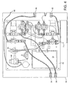
- the pneumatic circuit of the unit 30 is shown in Figure 3 .
- FIG. 3 shows the internals of the unit 30 diagrammatically.
- the casing itself is denoted 50, and as can be seen the major purge gas flow runs in a generally clockwise direction as shown in Figure 3 from a compressed nitrogen bottle 51 shown at the lower right hand corner via a standard high pressure lead and an inlet port 52 through a main feed line to the outlet port mounted on the front of the unit which is connected to the inlet port of the container.
- the outlet port of the container is connected to the inlet port on the front of the unit 30 and then passes through the unit 30 to a vent 55 located on the rear of the unit.
- branch lines 60 and 62 branch from the purge gas feed and exhaust and these may be selectively connected to the upstream side of a pump 64 which is in turn located upstream of an oxygen sensor unit through which gas may be passed, the downstream side of the sensor 66 being connected to a simple vent to atmosphere 68 located in the rear wall of the casing of unit 30.
- the main purge gas feed lines contain at the positions shown five solenoid operated valves S1 to S5, each being denoted NC for a valve which is normally closed when no power is applied and NO for one which is usually open when no power is applied.
- the interior of the case also includes electrical circuitry in particular for controlling the operation of the various solenoid valves and the pump 64, and which receives signals from appropriate pressure sensors and the oxygen sensor 66.
- a mains supply may be fed to the unit 32 using a normal power cord and plug arrangement 70 which is connected to a standard power supply unit 71 providing a 12 Volt output to drive the various electronic and electromechanical components.
- a main circuit board 73 which is powered from power supply 71 and which is connected in appropriate fashion to the display 39, a set of programming buttons 75 which are accessible from the front of the unit 30, some indicator LEDs 76, 77 and an audio transducer 78.
- the main printed circuit board 73 is also connected to appropriate driver circuits generally indicated at 78 for the solenoid valves, to a driver circuit 79 for pump 64 and to supply the appropriate voltage to the oxygen sensor controller generally designated 80.
- the electronic circuitry on board 73 may be arranged to operate in a variety of ways depending on its internal programming and on inputs from the buttons 75.
- the circuitry is programmed so that on powering up, there is brief self-test protocol which is carried out which checks the supply pressure of the gas supply connected to port 52 and that the relevant pressures are being achieved in various parts of the system under appropriate conditions. If there is a fault indication, this may be displayed on screen 39 enabling the operator to take appropriate action.
- Oxygen sensors are themselves sensitive pieces of equipment and often need recalibration.
- the initial self-testing protocol may include such calibration, or calibration may be initiated at any time by the user.
- the circuitry may also be set up to store a relevant parameter, for example, the oxygen detection level at which the purging of the interior of the container is judged to be sufficient. This may be adjusted by appropriate use of the buttons 75, which may have differing functions depending upon the programming of a control microprocessor on board 73, with the functions being indicated, for example, in customary fashion by an appropriate legend being displayed on the screen 39 by the side of each button 75.
- a relevant parameter for example, the oxygen detection level at which the purging of the interior of the container is judged to be sufficient.
- the unit may then indicate that it is ready to be used to purge a container.
- the operator may then connect a closed container to the ports 33 and 34 on the front of the unit 30 shown in Figure 3 and press an appropriate button to initiate a cycle of purging until analysis of the gas coming out of container 32 shows that the oxygen level has dropped to that pre-set, at which point the gas ceases to be injected into the container and the pressure within the container is allowed to drop to the desired positive pressure for storage.
- the container can then be disconnected from the unit and a new one reconnected to be purged in similar fashion.
- the end of the process may be signalled by unit 30, for example, by an appropriate indication from LED 76 and/or by a message on graphic display 39 and/or by an audible signal from transducer 78.
Landscapes
- Engineering & Computer Science (AREA)
- Mechanical Engineering (AREA)
- Life Sciences & Earth Sciences (AREA)
- Health & Medical Sciences (AREA)
- Chemical & Material Sciences (AREA)
- General Engineering & Computer Science (AREA)
- Analytical Chemistry (AREA)
- Pathology (AREA)
- Molecular Biology (AREA)
- Physics & Mathematics (AREA)
- Biomedical Technology (AREA)
- Biochemistry (AREA)
- General Health & Medical Sciences (AREA)
- General Physics & Mathematics (AREA)
- Immunology (AREA)
- Dispersion Chemistry (AREA)
- Filling Or Discharging Of Gas Storage Vessels (AREA)
- Packages (AREA)
- Sampling And Sample Adjustment (AREA)
- Investigating Or Analyzing Non-Biological Materials By The Use Of Chemical Means (AREA)
- Vacuum Packaging (AREA)
- Medical Preparation Storing Or Oral Administration Devices (AREA)
Abstract
Description
- This application relates to apparatus and methods for storing sensitive materials. In particular, it relates to systems in which sensitive materials are stored in a plurality of containers, each of which may constitute a sealed enclosure preventing the exchange of physical material between the external surroundings of the container, normally the ambient atmosphere, and the contents of the container. The contents are the sensitive material itself together with an appropriate atmosphere. The container may also include, for example, means for supporting the sensitive material itself.
-
US-A- 5855272 discloses a system of storing sensitive materials, in this particular case audio or audio-visual recordings, by placing them in an hermetically sealable container and purging the interior of the container with an inert gas such as nitrogen or argon. Following such purging the lid of the container may be finally closed to seal it and extra purge gas injected to render the pressure of the atmosphere in the interior of the container positive with respect to ambient, thus ensuring that any leakage, at least initially, transfers material from the inside of the container to the outside rather than letting anything from the outside in. -
US-A-5561915 discloses a container with an inbuilt carbon dioxide cartridge chamber. After the container is sealed, a cartridge is inserted into the chamber and acts to inject carbon dioxide into the interior, displacing the atmosphere therein which is exhausted via an exhaust orifice. After the atmosphere inside the container has been replaced with carbon dioxide, the spent cartridge is disposed of and the exhaust orifice sealed with a pipe plug. -
US-A-5960708 discloses stackable shipping containers consisting of a container having upper and lower members hermetically sealed together and with inlet and outlet valves to enable the interior of the container to be provided with gases to retard spoilage of food products within the container. -
US-A-5794408 discloses a method of inerting packaging covers, i.e. large flexible bags which surround items such as military equipment or packed for transportation. The covers are wholly sealed round the items save for two apertures, one for injecting inert gas into the bag, the other for extracting atmosphere from the bag, while always maintaining a virtual balance between the pressure inside the bag and the external ambient pressure. - A particular storage problem arises in the pharmaceutical and biotech industries in connection with the transportation and storage of sample materials. Particularly biotechnological materials tend to be unstable and need to be carefully handled. Not only must care be taken not to allow samples to be contaminated by dust, but it is desirable that they are protected from adverse effects from heat sources, light, or exposure to reactive materials such as-oxygen or moisture in the atmosphere.
- One particular area of substantial concern is the preservation of the compounds used in pharmaceutical research. These are very often highly sensitive and are conventionally handled and stored as a solution of the compound concerned in dimethyl sulphoxide. This is a very strong solvent for a very wide range of organic compounds and one which does not interact chemically with them. On the other hand the material itself, dimethyl sulphoxide, is highly hydrophilic, and accordingly tends to absorb moisture from the ambient atmosphere which can then interact with the compound in solution in the dimethyl sulphoxide. Accordingly, it is highly desirable to preserve and store such materials even though the sensitive materials are already in solution, in a controlled non-interactive environment because the solution itself can be categorised as a sensitive material.
- The present invention generally provides a system for the storage of sensitive materials as defined by claim 1, and a method for preserving sensitive materials as defined by
claim 6. - The apparatus may include a gas analysis or detection system to monitor the content of the exhaust gas, for example an oxygen sensor to detect the oxygen concentration in that gas, or a moisture content sensor.
- The apparatus preferably includes means to inject sufficient purge gas into the container to leave the container pressurised to assist in offsetting the adverse effect of any leakage of the seal. The degree to which it is pressurised may be chosen as desired, but is usually relatively small, particularly since if the pressure inside the sealed container is substantial relative to ambient pressure, there is not only a risk of the seal failing but additionally the sides of the container may bulge, so preventing clean stacking of a number of containers in a suitable storage facility.
- Regulations concerning pressurised systems and pressure vessels may also need to be respected, though it is more usual simply to use the apparatus to pressurise the container only to an extent not covered by such regulations.
- A preferred way of achieving the desired excess pressure in the container is to configure the purging apparatus so that after the purge gas has been injected sufficiently long for the exhaust gas to reach the acceptable condition, the pressure in the container is allowed to drop by venting gas from the interior of the container while measuring the pressure, and ceasing to vent gas once the desired excess pressure level is reached.
- Although it is often simple and convenient to purge the atmosphere inside the containers or on a container by container basis, it is possible to operate in other ways. For example, it is possible to purge a set of containers connected in series, with the source of purge gas connected to the inlet port of the first container in the series, the outlet port of the first container in the series connected to the inlet port of the second, and so on, the outlet port of the last container in the series being connected to the purge gas apparatus. Obviously the purging process will then take considerably longer to flush all of the existing ambient atmosphere from the containers, but overall time advantages may be gained by that sort of batch processing. In a further alternative, the purge gas outlet from the gassing apparatus may be distributed via a manifold to a plurality of inlets on a plurality of containers essentially arranged in parallel, the exhaust ports for each of the containers being likewise connected to a manifold which then connects to the inlet port on the gassing apparatus.
- The exact nature of the individual containers for sensitive products may vary widely, the fundamental requirements however being that the interior of the container may be sealed against the outside and that the container has an inlet port and outlet port. Within these constraints, the container may vary widely. It is convenient for many practical industrial applications to produce the containers in a number of standard sizes and the gassing apparatus may include a simple control to adjust the parameters such as gassing time, over-pressure and the like in accordance with the type and size of container in question.
- A preferred mode of construction of the containers is that of an open-topped box with a lid, the walls of the box and the material of the lid being of gas-impermeable material, for example sheet metal. Clearly sealing means need to be provided to enable the lid to be sealed to the edges of the open-topped box. This may be, for example, a resilient rubber or rubber-like material seal around the inside angled corner of a generally tray-shaped lid, and means may be provided on the open-topped box to enable the lid to be firmly held against the top of the open-topped box to seal its interior against the ambient atmosphere. Alternatively, the upper edges of the walls of the box may carry an annular seal strip of U-shaped cross section and made of an appropriate resilient sealing material.
- The inlet and outlet ports may be mounted on the walls of the box in customary sealed fashion. Preferably both ports are simple one-way or check valves. By providing that the exhaust port has an exhaust valve which opens only when the pressure within the container is above a preset level, the operation of purging the atmosphere from the interior of the container and then pressurising it may be rendered very straightforward.
- The interior of the containers may be provided if desired with any convenient fittings to assist the storage operation envisaged. For example, the interior may be divided into a number of compartments, for example six compartments in a 3 x 2 array, into each of which a standard unit may be inserted. For example, in handling biological samples, standard size so-called plate or tube racks are widely used and the storage container may be sized and shaped to enable an array of such racks to be easily accommodated.
- Preferably the inlet and outlet ports are standard pneumatic ports adapted for cooperating by a quick fit/quick release action with an appropriate fitting on the end of a tube such as a pressure line or exhaust line.
- The purge gas used in practising the present invention is conventionally nitrogen because it is inexpensive and effective though, for certain high specification areas, argon may be used. There is, of course, no reason not to use any other appropriate inert purge gas.
- The gassing apparatus may be constructed according to appropriate principles of engineering design and to suit the particular sensitive material storage problem envisaged. It will need to be provided with some form of power supply to operate and, of course, with a supply of purge gas, conveniently from a standard gas storage cylinder which may be connected to the gassing apparatus using conventional pressurised leads.
- The invention is illustrated by way of example only with reference to the accompanying drawings in which:
-
Figure 1 is a perspective view of a storage container and lid for use in the present invention; -
Figure 2 is a perspective view of a typical gassing apparatus shown connected to a container of the type illustrated inFigure 1 , -
Figure 3 is a diagram showing the internal pneumatic circuit and some associated electrical circuitry of the device shown inFigure 2 ; and - Referring to the drawings,
Figure 1 shows a container for use in practising the invention. It consists of a metal base section 1 and ametal lid 2 in the form of a plate having a depending skirt which is adapted to fit closely around the upper edge of the side wall of the base section 1. Mounted on the side of base section 1 are fourstandard clips 5, each of which has a portion adapted to engage over atab 6 located on the skirt oflid 2 and thereby urgelid 2 down towards base section 1. - Not shown in
Figure 1 is an internal annular seal which runs round the inside oflid 2 and which is of an appropriate resilient material such as a rubber or silicone compound. It is in the form of an even thickness bead into which the top edge of the side walls of base section 1 is urged as theclips 5 pull the lid downwards viatabs 6. - Two carrying
handles 8 are mounted on opposite sides of the skirt forming part oflid 2 so that once the base section 1 and thelid 2 are assembled and clipped together, the entire assembly can be lifted byhandles 8. - As shown in the drawing, the interior of the base has a set of dividing
walls 10 which may be a preformed structure which is a relatively loose fit in the base, and which divides the space within the base section 1 into six compartments, each of which may receive a standardsize sample array 12. Mounted on one wall of the base 1 is aninlet port 14 of conventional pneumatic construction. An exhaust port (not shown inFigure 1 ) is mounted on the opposite wall toport 14. -
Figure 2 shows a typical arrangement of a system in accordance with the present invention. On the right is a purge gas unit generally denoted 30 the on the left a container of the type shown infigure 1 and generally denoted 32. - As can be seen,
unit 30 consists of a generally rectangular casing having outlet andinlet ports pneumatic line 35 is connected between theoutlet port 33 of thepurge gas unit 30 and theinlet port 14 oncontainer 32. Apneumatic line 36 connects the outlet port oncontainer 32 withinlet port 34 on theunit 30. -
Unit 30 also has acontrol panel 38 including adisplay screen 39. Not shown infigure 2 are an electrical supply connection to unit 30 (which may be a normal mains lead which can be plugged in to any suitable electricity supply socket) and a source of purge gas, preferably a standard gas cylinder with the usual pressure reduction outlet valve mounted at its top and connected to an inlet port at the rear ofunit 30 via an appropriate pipe. - The pneumatic circuit of the
unit 30 is shown inFigure 3 . Referring to this figure, this shows the internals of theunit 30 diagrammatically. The casing itself is denoted 50, and as can be seen the major purge gas flow runs in a generally clockwise direction as shown inFigure 3 from acompressed nitrogen bottle 51 shown at the lower right hand corner via a standard high pressure lead and aninlet port 52 through a main feed line to the outlet port mounted on the front of the unit which is connected to the inlet port of the container. The outlet port of the container is connected to the inlet port on the front of theunit 30 and then passes through theunit 30 to avent 55 located on the rear of the unit. - As can-be seen in-
Figure 3 ,branch lines pump 64 which is in turn located upstream of an oxygen sensor unit through which gas may be passed, the downstream side of thesensor 66 being connected to a simple vent toatmosphere 68 located in the rear wall of the casing ofunit 30. - The main purge gas feed lines contain at the positions shown five solenoid operated valves S1 to S5, each being denoted NC for a valve which is normally closed when no power is applied and NO for one which is usually open when no power is applied.
- The interior of the case also includes electrical circuitry in particular for controlling the operation of the various solenoid valves and the
pump 64, and which receives signals from appropriate pressure sensors and theoxygen sensor 66. Thus as shown inFigure 3 , a mains supply may be fed to theunit 32 using a normal power cord and plugarrangement 70 which is connected to a standardpower supply unit 71 providing a 12 Volt output to drive the various electronic and electromechanical components. This is accomplished via the intermediation of amain circuit board 73 which is powered frompower supply 71 and which is connected in appropriate fashion to thedisplay 39, a set ofprogramming buttons 75 which are accessible from the front of theunit 30, someindicator LEDs audio transducer 78. The main printedcircuit board 73 is also connected to appropriate driver circuits generally indicated at 78 for the solenoid valves, to adriver circuit 79 forpump 64 and to supply the appropriate voltage to the oxygen sensor controller generally designated 80. - The electronic circuitry on
board 73 may be arranged to operate in a variety of ways depending on its internal programming and on inputs from thebuttons 75. In a preferred approach, the circuitry is programmed so that on powering up, there is brief self-test protocol which is carried out which checks the supply pressure of the gas supply connected toport 52 and that the relevant pressures are being achieved in various parts of the system under appropriate conditions. If there is a fault indication, this may be displayed onscreen 39 enabling the operator to take appropriate action. - Oxygen sensors are themselves sensitive pieces of equipment and often need recalibration. The initial self-testing protocol may include such calibration, or calibration may be initiated at any time by the user.
- The circuitry may also be set up to store a relevant parameter, for example, the oxygen detection level at which the purging of the interior of the container is judged to be sufficient. This may be adjusted by appropriate use of the
buttons 75, which may have differing functions depending upon the programming of a control microprocessor onboard 73, with the functions being indicated, for example, in customary fashion by an appropriate legend being displayed on thescreen 39 by the side of eachbutton 75. - Once the system has carried an appropriate self-testing protocol, and any error conditions attended to, for example, the purge gas supply not being connected to
port 52, the unit may then indicate that it is ready to be used to purge a container. The operator may then connect a closed container to theports unit 30 shown inFigure 3 and press an appropriate button to initiate a cycle of purging until analysis of the gas coming out ofcontainer 32 shows that the oxygen level has dropped to that pre-set, at which point the gas ceases to be injected into the container and the pressure within the container is allowed to drop to the desired positive pressure for storage. The container can then be disconnected from the unit and a new one reconnected to be purged in similar fashion. The end of the process may be signalled byunit 30, for example, by an appropriate indication fromLED 76 and/or by a message ongraphic display 39 and/or by an audible signal fromtransducer 78.
Claims (6)
- A system for the storage of sensitive materials, in a sealed container (32) having an inlet port (14), and an exhaust port, both ports being simple one-way or check valves, the system including apparatus adapted to inject an inert gas into a container (32) via the inlet port (14) thereof, and apparatus to measure a parameter of the gas within the container by monitoring gas removed from the container via the exhaust port thereof so that on detecting a desired condition of the gas in the container, the injection of further gas via the inlet port (14) of the container can be discontinued, the system includes a plurality of portable sealed containers (32) characterised in that each container (32) being a box having walls of a gas-impermeable material, that the gas injection apparatus and the monitoring apparatus are incorporated in a container interior conditioning apparatus (30), and that the conditioning apparatus (30) includes means to inject the inert gas under pressure into the container and emerge from the container via the exhaust port into the conditioning apparatus for monitoring therein, and means to allow inert gas to flow from the container (32) following the discontinuance of injection of the gas into the container (22) until the pressure within the container has dropped to a desired positive pressure for storage.
- A system according to Claim 1 wherein the conditioning apparatus (30) includes a gas analysis or detection system to monitor the content of the exhaust gas.
- A system according to Claim 2 wherein the gas analysis or detection system is adapted to monitor the oxygen content of the exhaust gas and includes an oxygen sensor (66) to detect the oxygen concentration in the exhaust gas.
- A system according to Claim 2 wherein the gas analysis or detection system is adapted to monitor the moisture content of the exhaust gas and includes a moisture sensor to detect the concentration of water vapour in the exhaust gas.
- A system according to any one of Claims 1 to 4 and including means to distribute purge gas from the container interior conditioning apparatus (30) via a manifold to a plurality of inlets (14) on a plurality of containers (32) arranged in parallel, the exhaust ports of the containers (32) being likewise connected to a manifold which then connects to an inlet port (34) on the container interior conditioning apparatus (30).
- A method of preserving sensitive materials which comprises placing the materials in a gas-impermeable container (32) with an inlet port (14) and an exhaust port, both ports being simple one-way or check valves, sealing the container (32) against the outside, injecting a purge gas from a purge gas apparatus into the inlet port (14), monitoring a parameter of the exhaust gas, detecting when the value of the parameter has reached a desired level, and stopping injection of the purge gas once that level has been reached, and the materials are placed in a series of containers (32), characterised in that each container (32) being a box having walls of gas-impermeable material, that gas injection apparatus and the monitoring means are located in the purge gas apparatus (30), and each container is sequentially connected to the purge gas apparatus (30), purge gas is injected under pressure into the container and the exhaust gas emerging as a result from the outlet port is monitored in the purge gas apparatus and, following the stopping of injection after the desired value of the parameter has been reached, the purge gas is allowed to continue to flow from the container until the pressure within the container has dropped to a desired positive pressure for storage, and each container is then disconnected from the purge gas apparatus.
Applications Claiming Priority (2)
| Application Number | Priority Date | Filing Date | Title |
|---|---|---|---|
| GB0501904A GB2422658A (en) | 2005-01-31 | 2005-01-31 | A method of flushing gas into an out of a sealable enclosure |
| PCT/GB2006/000307 WO2006095121A1 (en) | 2005-01-31 | 2006-01-30 | Apparatus and methods for storing sensitive materials |
Publications (2)
| Publication Number | Publication Date |
|---|---|
| EP1899704A1 EP1899704A1 (en) | 2008-03-19 |
| EP1899704B1 true EP1899704B1 (en) | 2012-07-11 |
Family
ID=34307690
Family Applications (1)
| Application Number | Title | Priority Date | Filing Date |
|---|---|---|---|
| EP06704225A Expired - Lifetime EP1899704B1 (en) | 2005-01-31 | 2006-01-30 | Apparatus and methods for storing sensitive materials |
Country Status (6)
| Country | Link |
|---|---|
| US (1) | US7878112B2 (en) |
| EP (1) | EP1899704B1 (en) |
| JP (1) | JP2008531399A (en) |
| GB (1) | GB2422658A (en) |
| PT (1) | PT1899704E (en) |
| WO (1) | WO2006095121A1 (en) |
Families Citing this family (12)
| Publication number | Priority date | Publication date | Assignee | Title |
|---|---|---|---|---|
| GB2422658A (en) * | 2005-01-31 | 2006-08-02 | Titude Ltd 4 | A method of flushing gas into an out of a sealable enclosure |
| GB0707305D0 (en) | 2007-04-16 | 2007-05-23 | Roylan Developments Ltd | Storage enclosures |
| GB2474302A (en) * | 2009-10-12 | 2011-04-13 | Roylan Developments Ltd | Gas purging a sealed container |
| EP2449304B1 (en) * | 2009-06-30 | 2017-03-01 | Roylan Developments Limited | Apparatus for purging containers for storing sensitive materials |
| GB2483249A (en) * | 2010-09-01 | 2012-03-07 | Inagas | Gas filling apparatus |
| US9027609B2 (en) * | 2011-05-03 | 2015-05-12 | United Technologies Corporation | Argon gas level controller |
| US9403117B2 (en) | 2013-02-07 | 2016-08-02 | Kevin Richard Hardy | Portable purge system |
| DK2848309T3 (en) * | 2013-09-13 | 2020-09-07 | Nanotemper Tech Gmbh | CARRIER FOR CAPITAL PIPES |
| US20150307217A1 (en) * | 2014-04-23 | 2015-10-29 | Fresh Box LLC | Food preservation system |
| CN116171109A (en) * | 2020-07-06 | 2023-05-26 | 格卢普有限责任公司 | Apparatus, system and method for modified atmosphere packaging |
| CN117775403B (en) * | 2024-01-02 | 2024-05-17 | 哈尔滨科海机械设备制造有限公司 | High-speed partial shipment vary voltage vacuum machine |
| CN117485654B (en) * | 2024-01-02 | 2024-03-22 | 哈尔滨科海机械设备制造有限公司 | Penicillin bottle high-speed split charging weighing and vacuumizing integrated machine |
Family Cites Families (31)
| Publication number | Priority date | Publication date | Assignee | Title |
|---|---|---|---|---|
| US3715860A (en) * | 1971-07-23 | 1973-02-13 | J Esty | Method of preserving perishable products |
| US4344467A (en) * | 1980-10-01 | 1982-08-17 | Lahde Frank U | Device for charging containers with an inert gas |
| US4707953A (en) * | 1983-03-30 | 1987-11-24 | Brunswick Corporation | Expandable shelter system providing collective protection |
| US4961322A (en) * | 1987-12-28 | 1990-10-09 | Aisin Seiki Kabushiki Kuisha | Fresh food storing device |
| JPH02242771A (en) | 1989-03-09 | 1990-09-27 | Fujitsu Ltd | Storage of magnetic recorder part |
| JPH0372332U (en) * | 1989-11-17 | 1991-07-22 | ||
| DE4133414A1 (en) * | 1991-10-09 | 1993-04-15 | Roland Dr Ing Wernecke | METHOD FOR MONITORING THE ENVIRONMENTAL HUMIDITY OF PACKED MOISTURE-SENSITIVE PRODUCTS AND PACKAGING MATERIAL SUITABLE FOR THIS |
| US5355781A (en) * | 1992-02-28 | 1994-10-18 | Prolong Systems, Inc. | Controlled atmosphere storage system |
| US6113671A (en) * | 1992-04-06 | 2000-09-05 | Garrett; Michael E. | Controlling atmospheres in containers |
| GB2271439A (en) * | 1992-10-07 | 1994-04-13 | Telektron Ltd | Gas pressurising and purging apparatus |
| BE1007847A3 (en) * | 1993-12-08 | 1995-11-07 | Madpack Servicos Internacionai | Concept inerting including process, machine, and complex soft sealed valves for sensitive products inerting moisture and oxygen. |
| GB9419765D0 (en) | 1994-09-30 | 1994-11-16 | Symons Richard D | Storage of sensitive media |
| US5561915A (en) | 1995-07-12 | 1996-10-08 | Vandergriff; Johnie B. | Storage container with sealed storage compartment for a purging gas cartridge |
| JPH1092918A (en) * | 1996-09-10 | 1998-04-10 | Matsushita Electron Corp | Semiconductor wafer carrier box and semiconductor wafer carrying method |
| US5799495A (en) * | 1996-10-30 | 1998-09-01 | Nitec, Inc. | Container oxygen control system for transporting and ripening perishable goods |
| US6013293A (en) * | 1997-09-10 | 2000-01-11 | Landec Corporation | Packing respiring biological materials with atmosphere control member |
| DE19753185A1 (en) * | 1997-11-21 | 1999-06-10 | Mannesmann Ag | Pet crate |
| IT1298836B1 (en) * | 1998-01-05 | 2000-02-07 | Edoardo Moscarelli | METHOD AND APPARATUS FOR THE STORAGE OF EQUIPMENT, MACHINERY AND MOBILE MEANS, IN CONTROLLED ATMOSPHERE. |
| US6023915A (en) * | 1998-10-29 | 2000-02-15 | Colombo Edward A | Modified atmosphere packaging method |
| US5960708A (en) * | 1998-06-16 | 1999-10-05 | Detemple; Donald Edward | Atmospheric controlled shipping container |
| FR2780618B1 (en) * | 1998-07-03 | 2000-08-04 | Air Liquide | PROCESS FOR MINIMIZING OXIDATION OF FOOD PRODUCTS |
| JP2000120992A (en) * | 1998-10-20 | 2000-04-28 | Nippon Sanso Corp | Gas filling method and gas filling device for gas container |
| JP2000128277A (en) * | 1998-10-23 | 2000-05-09 | Mitsubishi Kagaku Sanshi Corp | High airtight flexible container |
| CA2285748C (en) * | 1999-10-08 | 2010-05-25 | Louis Brown | Transportable collective protection system |
| DE10013501A1 (en) * | 2000-03-20 | 2001-11-29 | Ralph Gaebler | Atmosphere control for transport and storage of perishable goods involves setting composition of atmosphere depending on variation in trace gas concentration |
| JP2001298068A (en) * | 2000-04-18 | 2001-10-26 | Natl Inst Of Advanced Industrial Science & Technology Meti | Local cleaning method and local cleaning processing equipment |
| JP4292361B2 (en) * | 2002-03-14 | 2009-07-08 | 日本ゼオン株式会社 | Precision substrate protective film |
| US7228793B2 (en) * | 2002-11-25 | 2007-06-12 | Fizzy Fruit, LLC | Carbonation system for enhancing the flavor of fruits and vegetables |
| US20040262187A1 (en) * | 2003-06-26 | 2004-12-30 | Applied Materials, Inc. | Clean room transportation package for process chamber kit |
| US7650835B2 (en) * | 2004-01-26 | 2010-01-26 | Russ Stein | Produce ripening system |
| GB2422658A (en) * | 2005-01-31 | 2006-08-02 | Titude Ltd 4 | A method of flushing gas into an out of a sealable enclosure |
-
2005
- 2005-01-31 GB GB0501904A patent/GB2422658A/en not_active Withdrawn
-
2006
- 2006-01-30 WO PCT/GB2006/000307 patent/WO2006095121A1/en not_active Ceased
- 2006-01-30 PT PT06704225T patent/PT1899704E/en unknown
- 2006-01-30 US US11/883,296 patent/US7878112B2/en active Active
- 2006-01-30 EP EP06704225A patent/EP1899704B1/en not_active Expired - Lifetime
- 2006-01-30 JP JP2007552723A patent/JP2008531399A/en active Pending
Also Published As
| Publication number | Publication date |
|---|---|
| GB0501904D0 (en) | 2005-03-09 |
| US7878112B2 (en) | 2011-02-01 |
| EP1899704A1 (en) | 2008-03-19 |
| US20080099348A1 (en) | 2008-05-01 |
| GB2422658A (en) | 2006-08-02 |
| PT1899704E (en) | 2012-09-19 |
| JP2008531399A (en) | 2008-08-14 |
| WO2006095121A1 (en) | 2006-09-14 |
Similar Documents
| Publication | Publication Date | Title |
|---|---|---|
| US7878112B2 (en) | Apparatus and methods for storing sensitive materials | |
| TWI389829B (en) | System and method for transporting or storing oxidatively decomposable food products | |
| AU685883B2 (en) | Method for inerting packaging covers, devices therefor, and packaging cover used therein | |
| EP2449304B1 (en) | Apparatus for purging containers for storing sensitive materials | |
| US6354142B1 (en) | Process for testing the tightness of packages | |
| US20030182900A1 (en) | System and method for providing a regulated atmosphere for packaging perishable goods | |
| JP2009541998A5 (en) | ||
| JP2013509185A (en) | System and method for maintaining perishable foods | |
| US5488811A (en) | On-line air filter integrity testing apparatus | |
| US20240359846A1 (en) | Systems and methods for oxygen free packaging | |
| JP4574092B2 (en) | Leak detector | |
| CN109983316B (en) | Method for testing the tightness of a flexible container and use of an assembly in a method | |
| JP2009011930A (en) | Isolator | |
| JP2858689B2 (en) | Glove box | |
| JP2011036559A (en) | Sterilization and carry-in device | |
| JPH07159272A (en) | Pinhole inspection device for sealed packaging bags | |
| Elert et al. | Rentokil bubble in nitrogen anoxia treatment of museum pests | |
| JPH07159271A (en) | Pinhole inspection device for sealed packages | |
| EP4532364A1 (en) | Device for the packaging of products, particularly of the food type | |
| EP1469296A1 (en) | Process and apparatus for checking sealor tightness of a package made of flexible or semirigid material | |
| JP2010284404A (en) | Sterilization carry-in device | |
| CN112849494A (en) | High-efficient vacuum packaging system and vacuum packaging machine | |
| JPH07947A (en) | Inert gas seal type pure water storage device | |
| JPH08322376A (en) | Apparatus for controlled atmosphere (ca) storage | |
| JPH0799987B2 (en) | Fumigation method and equipment |
Legal Events
| Date | Code | Title | Description |
|---|---|---|---|
| PUAI | Public reference made under article 153(3) epc to a published international application that has entered the european phase |
Free format text: ORIGINAL CODE: 0009012 |
|
| 17P | Request for examination filed |
Effective date: 20071102 |
|
| AK | Designated contracting states |
Kind code of ref document: A1 Designated state(s): AT BE BG CH CY CZ DE DK EE ES FI FR GB GR HU IE IS IT LI LT LU LV MC NL PL PT RO SE SI SK TR |
|
| DAX | Request for extension of the european patent (deleted) | ||
| 17Q | First examination report despatched |
Effective date: 20101217 |
|
| GRAP | Despatch of communication of intention to grant a patent |
Free format text: ORIGINAL CODE: EPIDOSNIGR1 |
|
| GRAS | Grant fee paid |
Free format text: ORIGINAL CODE: EPIDOSNIGR3 |
|
| GRAA | (expected) grant |
Free format text: ORIGINAL CODE: 0009210 |
|
| AK | Designated contracting states |
Kind code of ref document: B1 Designated state(s): AT BE BG CH CY CZ DE DK EE ES FI FR GB GR HU IE IS IT LI LT LU LV MC NL PL PT RO SE SI SK TR |
|
| REG | Reference to a national code |
Ref country code: GB Ref legal event code: FG4D |
|
| REG | Reference to a national code |
Ref country code: CH Ref legal event code: EP |
|
| REG | Reference to a national code |
Ref country code: AT Ref legal event code: REF Ref document number: 566375 Country of ref document: AT Kind code of ref document: T Effective date: 20120715 |
|
| REG | Reference to a national code |
Ref country code: IE Ref legal event code: FG4D |
|
| REG | Reference to a national code |
Ref country code: DE Ref legal event code: R096 Ref document number: 602006030665 Country of ref document: DE Effective date: 20120906 |
|
| REG | Reference to a national code |
Ref country code: CH Ref legal event code: NV Representative=s name: ZIMMERLI, WAGNER & PARTNER AG |
|
| REG | Reference to a national code |
Ref country code: PT Ref legal event code: SC4A Free format text: AVAILABILITY OF NATIONAL TRANSLATION Effective date: 20120912 |
|
| REG | Reference to a national code |
Ref country code: SE Ref legal event code: TRGR |
|
| REG | Reference to a national code |
Ref country code: NL Ref legal event code: T3 |
|
| REG | Reference to a national code |
Ref country code: AT Ref legal event code: MK05 Ref document number: 566375 Country of ref document: AT Kind code of ref document: T Effective date: 20120711 |
|
| REG | Reference to a national code |
Ref country code: LT Ref legal event code: MG4D Effective date: 20120711 |
|
| PG25 | Lapsed in a contracting state [announced via postgrant information from national office to epo] |
Ref country code: LT Free format text: LAPSE BECAUSE OF FAILURE TO SUBMIT A TRANSLATION OF THE DESCRIPTION OR TO PAY THE FEE WITHIN THE PRESCRIBED TIME-LIMIT Effective date: 20120711 Ref country code: IS Free format text: LAPSE BECAUSE OF FAILURE TO SUBMIT A TRANSLATION OF THE DESCRIPTION OR TO PAY THE FEE WITHIN THE PRESCRIBED TIME-LIMIT Effective date: 20121111 Ref country code: CY Free format text: LAPSE BECAUSE OF FAILURE TO SUBMIT A TRANSLATION OF THE DESCRIPTION OR TO PAY THE FEE WITHIN THE PRESCRIBED TIME-LIMIT Effective date: 20120711 Ref country code: AT Free format text: LAPSE BECAUSE OF FAILURE TO SUBMIT A TRANSLATION OF THE DESCRIPTION OR TO PAY THE FEE WITHIN THE PRESCRIBED TIME-LIMIT Effective date: 20120711 |
|
| PG25 | Lapsed in a contracting state [announced via postgrant information from national office to epo] |
Ref country code: PL Free format text: LAPSE BECAUSE OF FAILURE TO SUBMIT A TRANSLATION OF THE DESCRIPTION OR TO PAY THE FEE WITHIN THE PRESCRIBED TIME-LIMIT Effective date: 20120711 Ref country code: LV Free format text: LAPSE BECAUSE OF FAILURE TO SUBMIT A TRANSLATION OF THE DESCRIPTION OR TO PAY THE FEE WITHIN THE PRESCRIBED TIME-LIMIT Effective date: 20120711 Ref country code: SI Free format text: LAPSE BECAUSE OF FAILURE TO SUBMIT A TRANSLATION OF THE DESCRIPTION OR TO PAY THE FEE WITHIN THE PRESCRIBED TIME-LIMIT Effective date: 20120711 Ref country code: GR Free format text: LAPSE BECAUSE OF FAILURE TO SUBMIT A TRANSLATION OF THE DESCRIPTION OR TO PAY THE FEE WITHIN THE PRESCRIBED TIME-LIMIT Effective date: 20121012 |
|
| PG25 | Lapsed in a contracting state [announced via postgrant information from national office to epo] |
Ref country code: RO Free format text: LAPSE BECAUSE OF FAILURE TO SUBMIT A TRANSLATION OF THE DESCRIPTION OR TO PAY THE FEE WITHIN THE PRESCRIBED TIME-LIMIT Effective date: 20120711 Ref country code: DK Free format text: LAPSE BECAUSE OF FAILURE TO SUBMIT A TRANSLATION OF THE DESCRIPTION OR TO PAY THE FEE WITHIN THE PRESCRIBED TIME-LIMIT Effective date: 20120711 Ref country code: ES Free format text: LAPSE BECAUSE OF FAILURE TO SUBMIT A TRANSLATION OF THE DESCRIPTION OR TO PAY THE FEE WITHIN THE PRESCRIBED TIME-LIMIT Effective date: 20121022 Ref country code: EE Free format text: LAPSE BECAUSE OF FAILURE TO SUBMIT A TRANSLATION OF THE DESCRIPTION OR TO PAY THE FEE WITHIN THE PRESCRIBED TIME-LIMIT Effective date: 20120711 Ref country code: CZ Free format text: LAPSE BECAUSE OF FAILURE TO SUBMIT A TRANSLATION OF THE DESCRIPTION OR TO PAY THE FEE WITHIN THE PRESCRIBED TIME-LIMIT Effective date: 20120711 |
|
| PLBE | No opposition filed within time limit |
Free format text: ORIGINAL CODE: 0009261 |
|
| STAA | Information on the status of an ep patent application or granted ep patent |
Free format text: STATUS: NO OPPOSITION FILED WITHIN TIME LIMIT |
|
| PG25 | Lapsed in a contracting state [announced via postgrant information from national office to epo] |
Ref country code: IT Free format text: LAPSE BECAUSE OF FAILURE TO SUBMIT A TRANSLATION OF THE DESCRIPTION OR TO PAY THE FEE WITHIN THE PRESCRIBED TIME-LIMIT Effective date: 20120711 Ref country code: SK Free format text: LAPSE BECAUSE OF FAILURE TO SUBMIT A TRANSLATION OF THE DESCRIPTION OR TO PAY THE FEE WITHIN THE PRESCRIBED TIME-LIMIT Effective date: 20120711 |
|
| 26N | No opposition filed |
Effective date: 20130412 |
|
| PG25 | Lapsed in a contracting state [announced via postgrant information from national office to epo] |
Ref country code: BG Free format text: LAPSE BECAUSE OF FAILURE TO SUBMIT A TRANSLATION OF THE DESCRIPTION OR TO PAY THE FEE WITHIN THE PRESCRIBED TIME-LIMIT Effective date: 20121011 |
|
| REG | Reference to a national code |
Ref country code: DE Ref legal event code: R097 Ref document number: 602006030665 Country of ref document: DE Effective date: 20130412 |
|
| PG25 | Lapsed in a contracting state [announced via postgrant information from national office to epo] |
Ref country code: MC Free format text: LAPSE BECAUSE OF NON-PAYMENT OF DUE FEES Effective date: 20130131 |
|
| REG | Reference to a national code |
Ref country code: CH Ref legal event code: NV Representative=s name: WAGNER PATENT AG, CH |
|
| PG25 | Lapsed in a contracting state [announced via postgrant information from national office to epo] |
Ref country code: TR Free format text: LAPSE BECAUSE OF FAILURE TO SUBMIT A TRANSLATION OF THE DESCRIPTION OR TO PAY THE FEE WITHIN THE PRESCRIBED TIME-LIMIT Effective date: 20120711 |
|
| PG25 | Lapsed in a contracting state [announced via postgrant information from national office to epo] |
Ref country code: HU Free format text: LAPSE BECAUSE OF FAILURE TO SUBMIT A TRANSLATION OF THE DESCRIPTION OR TO PAY THE FEE WITHIN THE PRESCRIBED TIME-LIMIT; INVALID AB INITIO Effective date: 20060130 Ref country code: LU Free format text: LAPSE BECAUSE OF NON-PAYMENT OF DUE FEES Effective date: 20130130 |
|
| REG | Reference to a national code |
Ref country code: FR Ref legal event code: PLFP Year of fee payment: 11 |
|
| REG | Reference to a national code |
Ref country code: FR Ref legal event code: PLFP Year of fee payment: 12 |
|
| REG | Reference to a national code |
Ref country code: FR Ref legal event code: PLFP Year of fee payment: 13 |
|
| PGFP | Annual fee paid to national office [announced via postgrant information from national office to epo] |
Ref country code: PT Payment date: 20210119 Year of fee payment: 16 Ref country code: NL Payment date: 20210113 Year of fee payment: 16 |
|
| PGFP | Annual fee paid to national office [announced via postgrant information from national office to epo] |
Ref country code: BE Payment date: 20210126 Year of fee payment: 16 Ref country code: SE Payment date: 20210118 Year of fee payment: 16 |
|
| REG | Reference to a national code |
Ref country code: SE Ref legal event code: EUG |
|
| REG | Reference to a national code |
Ref country code: NL Ref legal event code: MM Effective date: 20220201 |
|
| REG | Reference to a national code |
Ref country code: BE Ref legal event code: MM Effective date: 20220131 |
|
| PG25 | Lapsed in a contracting state [announced via postgrant information from national office to epo] |
Ref country code: SE Free format text: LAPSE BECAUSE OF NON-PAYMENT OF DUE FEES Effective date: 20220131 Ref country code: PT Free format text: LAPSE BECAUSE OF NON-PAYMENT OF DUE FEES Effective date: 20220801 Ref country code: NL Free format text: LAPSE BECAUSE OF NON-PAYMENT OF DUE FEES Effective date: 20220201 |
|
| PG25 | Lapsed in a contracting state [announced via postgrant information from national office to epo] |
Ref country code: BE Free format text: LAPSE BECAUSE OF NON-PAYMENT OF DUE FEES Effective date: 20220131 |
|
| PGFP | Annual fee paid to national office [announced via postgrant information from national office to epo] |
Ref country code: IE Payment date: 20230108 Year of fee payment: 18 Ref country code: FR Payment date: 20230118 Year of fee payment: 18 Ref country code: FI Payment date: 20230116 Year of fee payment: 18 Ref country code: CH Payment date: 20230117 Year of fee payment: 18 |
|
| PGFP | Annual fee paid to national office [announced via postgrant information from national office to epo] |
Ref country code: DE Payment date: 20230111 Year of fee payment: 18 |
|
| REG | Reference to a national code |
Ref country code: DE Ref legal event code: R119 Ref document number: 602006030665 Country of ref document: DE |
|
| REG | Reference to a national code |
Ref country code: CH Ref legal event code: PL |
|
| PG25 | Lapsed in a contracting state [announced via postgrant information from national office to epo] |
Ref country code: FI Free format text: LAPSE BECAUSE OF NON-PAYMENT OF DUE FEES Effective date: 20240130 Ref country code: DE Free format text: LAPSE BECAUSE OF NON-PAYMENT OF DUE FEES Effective date: 20240801 |
|
| PG25 | Lapsed in a contracting state [announced via postgrant information from national office to epo] |
Ref country code: FR Free format text: LAPSE BECAUSE OF NON-PAYMENT OF DUE FEES Effective date: 20240131 |
|
| PG25 | Lapsed in a contracting state [announced via postgrant information from national office to epo] |
Ref country code: CH Free format text: LAPSE BECAUSE OF NON-PAYMENT OF DUE FEES Effective date: 20240131 |
|
| PG25 | Lapsed in a contracting state [announced via postgrant information from national office to epo] |
Ref country code: FR Free format text: LAPSE BECAUSE OF NON-PAYMENT OF DUE FEES Effective date: 20240131 Ref country code: FI Free format text: LAPSE BECAUSE OF NON-PAYMENT OF DUE FEES Effective date: 20240130 Ref country code: DE Free format text: LAPSE BECAUSE OF NON-PAYMENT OF DUE FEES Effective date: 20240801 Ref country code: CH Free format text: LAPSE BECAUSE OF NON-PAYMENT OF DUE FEES Effective date: 20240131 |
|
| PG25 | Lapsed in a contracting state [announced via postgrant information from national office to epo] |
Ref country code: IE Free format text: LAPSE BECAUSE OF NON-PAYMENT OF DUE FEES Effective date: 20240130 |
|
| PG25 | Lapsed in a contracting state [announced via postgrant information from national office to epo] |
Ref country code: IE Free format text: LAPSE BECAUSE OF NON-PAYMENT OF DUE FEES Effective date: 20240130 |
|
| PGFP | Annual fee paid to national office [announced via postgrant information from national office to epo] |
Ref country code: GB Payment date: 20250130 Year of fee payment: 20 |
|
| REG | Reference to a national code |
Ref country code: GB Ref legal event code: PE20 Expiry date: 20260129 |