EP1899143B1 - Gerät und verfahren zum herstellen eines geräts - Google Patents
Gerät und verfahren zum herstellen eines geräts Download PDFInfo
- Publication number
- EP1899143B1 EP1899143B1 EP06763486A EP06763486A EP1899143B1 EP 1899143 B1 EP1899143 B1 EP 1899143B1 EP 06763486 A EP06763486 A EP 06763486A EP 06763486 A EP06763486 A EP 06763486A EP 1899143 B1 EP1899143 B1 EP 1899143B1
- Authority
- EP
- European Patent Office
- Prior art keywords
- housing
- bending arm
- contact region
- laser beam
- region
- Prior art date
- Legal status (The legal status is an assumption and is not a legal conclusion. Google has not performed a legal analysis and makes no representation as to the accuracy of the status listed.)
- Not-in-force
Links
Images
Classifications
-
- B—PERFORMING OPERATIONS; TRANSPORTING
- B29—WORKING OF PLASTICS; WORKING OF SUBSTANCES IN A PLASTIC STATE IN GENERAL
- B29C—SHAPING OR JOINING OF PLASTICS; SHAPING OF MATERIAL IN A PLASTIC STATE, NOT OTHERWISE PROVIDED FOR; AFTER-TREATMENT OF THE SHAPED PRODUCTS, e.g. REPAIRING
- B29C66/00—General aspects of processes or apparatus for joining preformed parts
- B29C66/50—General aspects of joining tubular articles; General aspects of joining long products, i.e. bars or profiled elements; General aspects of joining single elements to tubular articles, hollow articles or bars; General aspects of joining several hollow-preforms to form hollow or tubular articles
- B29C66/51—Joining tubular articles, profiled elements or bars; Joining single elements to tubular articles, hollow articles or bars; Joining several hollow-preforms to form hollow or tubular articles
- B29C66/54—Joining several hollow-preforms, e.g. half-shells, to form hollow articles, e.g. for making balls, containers; Joining several hollow-preforms, e.g. half-cylinders, to form tubular articles
-
- B—PERFORMING OPERATIONS; TRANSPORTING
- B29—WORKING OF PLASTICS; WORKING OF SUBSTANCES IN A PLASTIC STATE IN GENERAL
- B29C—SHAPING OR JOINING OF PLASTICS; SHAPING OF MATERIAL IN A PLASTIC STATE, NOT OTHERWISE PROVIDED FOR; AFTER-TREATMENT OF THE SHAPED PRODUCTS, e.g. REPAIRING
- B29C65/00—Joining or sealing of preformed parts, e.g. welding of plastics materials; Apparatus therefor
- B29C65/02—Joining or sealing of preformed parts, e.g. welding of plastics materials; Apparatus therefor by heating, with or without pressure
- B29C65/14—Joining or sealing of preformed parts, e.g. welding of plastics materials; Apparatus therefor by heating, with or without pressure using wave energy, i.e. electromagnetic radiation, or particle radiation
- B29C65/16—Laser beams
- B29C65/1629—Laser beams characterised by the way of heating the interface
- B29C65/1635—Laser beams characterised by the way of heating the interface at least passing through one of the parts to be joined, i.e. laser transmission welding
-
- B—PERFORMING OPERATIONS; TRANSPORTING
- B29—WORKING OF PLASTICS; WORKING OF SUBSTANCES IN A PLASTIC STATE IN GENERAL
- B29C—SHAPING OR JOINING OF PLASTICS; SHAPING OF MATERIAL IN A PLASTIC STATE, NOT OTHERWISE PROVIDED FOR; AFTER-TREATMENT OF THE SHAPED PRODUCTS, e.g. REPAIRING
- B29C65/00—Joining or sealing of preformed parts, e.g. welding of plastics materials; Apparatus therefor
- B29C65/02—Joining or sealing of preformed parts, e.g. welding of plastics materials; Apparatus therefor by heating, with or without pressure
- B29C65/14—Joining or sealing of preformed parts, e.g. welding of plastics materials; Apparatus therefor by heating, with or without pressure using wave energy, i.e. electromagnetic radiation, or particle radiation
- B29C65/16—Laser beams
- B29C65/1629—Laser beams characterised by the way of heating the interface
- B29C65/1664—Laser beams characterised by the way of heating the interface making use of several radiators
-
- B—PERFORMING OPERATIONS; TRANSPORTING
- B29—WORKING OF PLASTICS; WORKING OF SUBSTANCES IN A PLASTIC STATE IN GENERAL
- B29C—SHAPING OR JOINING OF PLASTICS; SHAPING OF MATERIAL IN A PLASTIC STATE, NOT OTHERWISE PROVIDED FOR; AFTER-TREATMENT OF THE SHAPED PRODUCTS, e.g. REPAIRING
- B29C66/00—General aspects of processes or apparatus for joining preformed parts
- B29C66/50—General aspects of joining tubular articles; General aspects of joining long products, i.e. bars or profiled elements; General aspects of joining single elements to tubular articles, hollow articles or bars; General aspects of joining several hollow-preforms to form hollow or tubular articles
- B29C66/51—Joining tubular articles, profiled elements or bars; Joining single elements to tubular articles, hollow articles or bars; Joining several hollow-preforms to form hollow or tubular articles
- B29C66/54—Joining several hollow-preforms, e.g. half-shells, to form hollow articles, e.g. for making balls, containers; Joining several hollow-preforms, e.g. half-cylinders, to form tubular articles
- B29C66/543—Joining several hollow-preforms, e.g. half-shells, to form hollow articles, e.g. for making balls, containers; Joining several hollow-preforms, e.g. half-cylinders, to form tubular articles joining more than two hollow-preforms to form said hollow articles
-
- B—PERFORMING OPERATIONS; TRANSPORTING
- B60—VEHICLES IN GENERAL
- B60T—VEHICLE BRAKE CONTROL SYSTEMS OR PARTS THEREOF; BRAKE CONTROL SYSTEMS OR PARTS THEREOF, IN GENERAL; ARRANGEMENT OF BRAKING ELEMENTS ON VEHICLES IN GENERAL; PORTABLE DEVICES FOR PREVENTING UNWANTED MOVEMENT OF VEHICLES; VEHICLE MODIFICATIONS TO FACILITATE COOLING OF BRAKES
- B60T8/00—Arrangements for adjusting wheel-braking force to meet varying vehicular or ground-surface conditions, e.g. limiting or varying distribution of braking force
- B60T8/32—Arrangements for adjusting wheel-braking force to meet varying vehicular or ground-surface conditions, e.g. limiting or varying distribution of braking force responsive to a speed condition, e.g. acceleration or deceleration
- B60T8/34—Arrangements for adjusting wheel-braking force to meet varying vehicular or ground-surface conditions, e.g. limiting or varying distribution of braking force responsive to a speed condition, e.g. acceleration or deceleration having a fluid pressure regulator responsive to a speed condition
- B60T8/36—Arrangements for adjusting wheel-braking force to meet varying vehicular or ground-surface conditions, e.g. limiting or varying distribution of braking force responsive to a speed condition, e.g. acceleration or deceleration having a fluid pressure regulator responsive to a speed condition including a pilot valve responding to an electromagnetic force
- B60T8/3615—Electromagnetic valves specially adapted for anti-lock brake and traction control systems
- B60T8/3675—Electromagnetic valves specially adapted for anti-lock brake and traction control systems integrated in modulator units
-
- B—PERFORMING OPERATIONS; TRANSPORTING
- B29—WORKING OF PLASTICS; WORKING OF SUBSTANCES IN A PLASTIC STATE IN GENERAL
- B29C—SHAPING OR JOINING OF PLASTICS; SHAPING OF MATERIAL IN A PLASTIC STATE, NOT OTHERWISE PROVIDED FOR; AFTER-TREATMENT OF THE SHAPED PRODUCTS, e.g. REPAIRING
- B29C65/00—Joining or sealing of preformed parts, e.g. welding of plastics materials; Apparatus therefor
- B29C65/02—Joining or sealing of preformed parts, e.g. welding of plastics materials; Apparatus therefor by heating, with or without pressure
- B29C65/14—Joining or sealing of preformed parts, e.g. welding of plastics materials; Apparatus therefor by heating, with or without pressure using wave energy, i.e. electromagnetic radiation, or particle radiation
- B29C65/16—Laser beams
- B29C65/1603—Laser beams characterised by the type of electromagnetic radiation
- B29C65/1612—Infrared [IR] radiation, e.g. by infrared lasers
- B29C65/1616—Near infrared radiation [NIR], e.g. by YAG lasers
-
- B—PERFORMING OPERATIONS; TRANSPORTING
- B29—WORKING OF PLASTICS; WORKING OF SUBSTANCES IN A PLASTIC STATE IN GENERAL
- B29C—SHAPING OR JOINING OF PLASTICS; SHAPING OF MATERIAL IN A PLASTIC STATE, NOT OTHERWISE PROVIDED FOR; AFTER-TREATMENT OF THE SHAPED PRODUCTS, e.g. REPAIRING
- B29C65/00—Joining or sealing of preformed parts, e.g. welding of plastics materials; Apparatus therefor
- B29C65/02—Joining or sealing of preformed parts, e.g. welding of plastics materials; Apparatus therefor by heating, with or without pressure
- B29C65/14—Joining or sealing of preformed parts, e.g. welding of plastics materials; Apparatus therefor by heating, with or without pressure using wave energy, i.e. electromagnetic radiation, or particle radiation
- B29C65/16—Laser beams
- B29C65/1629—Laser beams characterised by the way of heating the interface
- B29C65/1664—Laser beams characterised by the way of heating the interface making use of several radiators
- B29C65/1667—Laser beams characterised by the way of heating the interface making use of several radiators at the same time, i.e. simultaneous laser welding
-
- B—PERFORMING OPERATIONS; TRANSPORTING
- B29—WORKING OF PLASTICS; WORKING OF SUBSTANCES IN A PLASTIC STATE IN GENERAL
- B29C—SHAPING OR JOINING OF PLASTICS; SHAPING OF MATERIAL IN A PLASTIC STATE, NOT OTHERWISE PROVIDED FOR; AFTER-TREATMENT OF THE SHAPED PRODUCTS, e.g. REPAIRING
- B29C65/00—Joining or sealing of preformed parts, e.g. welding of plastics materials; Apparatus therefor
- B29C65/02—Joining or sealing of preformed parts, e.g. welding of plastics materials; Apparatus therefor by heating, with or without pressure
- B29C65/14—Joining or sealing of preformed parts, e.g. welding of plastics materials; Apparatus therefor by heating, with or without pressure using wave energy, i.e. electromagnetic radiation, or particle radiation
- B29C65/16—Laser beams
- B29C65/1696—Laser beams making use of masks
-
- B—PERFORMING OPERATIONS; TRANSPORTING
- B29—WORKING OF PLASTICS; WORKING OF SUBSTANCES IN A PLASTIC STATE IN GENERAL
- B29C—SHAPING OR JOINING OF PLASTICS; SHAPING OF MATERIAL IN A PLASTIC STATE, NOT OTHERWISE PROVIDED FOR; AFTER-TREATMENT OF THE SHAPED PRODUCTS, e.g. REPAIRING
- B29C66/00—General aspects of processes or apparatus for joining preformed parts
- B29C66/50—General aspects of joining tubular articles; General aspects of joining long products, i.e. bars or profiled elements; General aspects of joining single elements to tubular articles, hollow articles or bars; General aspects of joining several hollow-preforms to form hollow or tubular articles
- B29C66/51—Joining tubular articles, profiled elements or bars; Joining single elements to tubular articles, hollow articles or bars; Joining several hollow-preforms to form hollow or tubular articles
- B29C66/54—Joining several hollow-preforms, e.g. half-shells, to form hollow articles, e.g. for making balls, containers; Joining several hollow-preforms, e.g. half-cylinders, to form tubular articles
- B29C66/542—Joining several hollow-preforms, e.g. half-shells, to form hollow articles, e.g. for making balls, containers; Joining several hollow-preforms, e.g. half-cylinders, to form tubular articles joining hollow covers or hollow bottoms to open ends of container bodies
-
- B—PERFORMING OPERATIONS; TRANSPORTING
- B29—WORKING OF PLASTICS; WORKING OF SUBSTANCES IN A PLASTIC STATE IN GENERAL
- B29C—SHAPING OR JOINING OF PLASTICS; SHAPING OF MATERIAL IN A PLASTIC STATE, NOT OTHERWISE PROVIDED FOR; AFTER-TREATMENT OF THE SHAPED PRODUCTS, e.g. REPAIRING
- B29C66/00—General aspects of processes or apparatus for joining preformed parts
- B29C66/70—General aspects of processes or apparatus for joining preformed parts characterised by the composition, physical properties or the structure of the material of the parts to be joined; Joining with non-plastics material
- B29C66/71—General aspects of processes or apparatus for joining preformed parts characterised by the composition, physical properties or the structure of the material of the parts to be joined; Joining with non-plastics material characterised by the composition of the plastics material of the parts to be joined
-
- B—PERFORMING OPERATIONS; TRANSPORTING
- B29—WORKING OF PLASTICS; WORKING OF SUBSTANCES IN A PLASTIC STATE IN GENERAL
- B29C—SHAPING OR JOINING OF PLASTICS; SHAPING OF MATERIAL IN A PLASTIC STATE, NOT OTHERWISE PROVIDED FOR; AFTER-TREATMENT OF THE SHAPED PRODUCTS, e.g. REPAIRING
- B29C66/00—General aspects of processes or apparatus for joining preformed parts
- B29C66/70—General aspects of processes or apparatus for joining preformed parts characterised by the composition, physical properties or the structure of the material of the parts to be joined; Joining with non-plastics material
- B29C66/73—General aspects of processes or apparatus for joining preformed parts characterised by the composition, physical properties or the structure of the material of the parts to be joined; Joining with non-plastics material characterised by the intensive physical properties of the material of the parts to be joined, by the optical properties of the material of the parts to be joined, by the extensive physical properties of the parts to be joined, by the state of the material of the parts to be joined or by the material of the parts to be joined being a thermoplastic or a thermoset
- B29C66/739—General aspects of processes or apparatus for joining preformed parts characterised by the composition, physical properties or the structure of the material of the parts to be joined; Joining with non-plastics material characterised by the intensive physical properties of the material of the parts to be joined, by the optical properties of the material of the parts to be joined, by the extensive physical properties of the parts to be joined, by the state of the material of the parts to be joined or by the material of the parts to be joined being a thermoplastic or a thermoset characterised by the material of the parts to be joined being a thermoplastic or a thermoset
- B29C66/7392—General aspects of processes or apparatus for joining preformed parts characterised by the composition, physical properties or the structure of the material of the parts to be joined; Joining with non-plastics material characterised by the intensive physical properties of the material of the parts to be joined, by the optical properties of the material of the parts to be joined, by the extensive physical properties of the parts to be joined, by the state of the material of the parts to be joined or by the material of the parts to be joined being a thermoplastic or a thermoset characterised by the material of the parts to be joined being a thermoplastic or a thermoset characterised by the material of at least one of the parts being a thermoplastic
- B29C66/73921—General aspects of processes or apparatus for joining preformed parts characterised by the composition, physical properties or the structure of the material of the parts to be joined; Joining with non-plastics material characterised by the intensive physical properties of the material of the parts to be joined, by the optical properties of the material of the parts to be joined, by the extensive physical properties of the parts to be joined, by the state of the material of the parts to be joined or by the material of the parts to be joined being a thermoplastic or a thermoset characterised by the material of the parts to be joined being a thermoplastic or a thermoset characterised by the material of at least one of the parts being a thermoplastic characterised by the materials of both parts being thermoplastics
-
- B—PERFORMING OPERATIONS; TRANSPORTING
- B29—WORKING OF PLASTICS; WORKING OF SUBSTANCES IN A PLASTIC STATE IN GENERAL
- B29K—INDEXING SCHEME ASSOCIATED WITH SUBCLASSES B29B, B29C OR B29D, RELATING TO MOULDING MATERIALS OR TO MATERIALS FOR MOULDS, REINFORCEMENTS, FILLERS OR PREFORMED PARTS, e.g. INSERTS
- B29K2067/00—Use of polyesters or derivatives thereof, as moulding material
- B29K2067/006—PBT, i.e. polybutylene terephthalate
Definitions
- the invention relates to a device and a method for producing a device with a housing and with a frame element, which is arranged within the housing and which accommodates at least one component.
- a device may be, for example, a control device for an internal combustion engine or also a control device for an electrically adjustable brake of a vehicle, which uses an electromotive actuator to generate a braking force which is supplied to the respective brakes on wheels of a vehicle.
- melt causes a transfer of heat between the two parts to be joined, and thus also the joining part which is permeable to the laser radiation is melted.
- the intensity of the absorption is determined by the chosen material and its additives as well as by the wavelength of the radiation source.
- the object of the invention is to provide a method of manufacturing a device by means of which a compact device can be easily manufactured.
- the object of the invention is, in a second aspect, to provide a device which is compact.
- the invention is characterized according to a first aspect by a method for producing a device comprising a housing and a frame element, which is arranged within the housing, which accommodates at least one component, in particular an electrical or electronic component, and which has at least one bending arm.
- the bending arm is formed so that a contact region of the bending arm rests in a, in particular free, mounted state within the housing at a contact region of a wall of the housing with prestress.
- the bending arm is preferably elastically bendable and designed so that it is elastically deflected in the freely mounted state within the housing by a wall of the housing and thus this is applied with bias.
- the bending arm is integrally bonded to the housing by means of laser beam welding and is transmitted by applying a laser beam of predetermined wavelength to the device in such a way that the laser beam is transmitted through the housing towards the contact region of the bending arm.
- the Housing is made of a material that is transparent to the predetermined wavelength of the laser beam at least in a region through which the laser beam is transmitted.
- the contact region of the bending arm is made of a material that is absorbent for the given wavelength of the laser beam.
- the method is characterized in that the device can be made particularly compact and at the same time a reliable fixing of the frame member is easily possible, even if it is completely enclosed by the housing.
- the bending arm is formed so elastic that it rests with a predetermined bias in the assembled state at the contact region of the housing and on the other hand stiff enough to compensate for vibrations to which the frame member is exposed.
- a nose is formed at the contact region of the bending arm.
- both the bias can be adjusted easily suitable, it can be easily achieved a favorable mass distribution of the material to be melted by transmission welding and a compared to the Brockvorensein the nose of larger area can be used for welding.
- This has the advantage that a defined contact contour is formed even with different bending of the bending arm. For example, in the case of a partial spherical formation of the nose, the contact contour depends only on the radius of the partial sphere.
- a shielding body is formed on the bending arm, which is remote from the contact region of the housing with respect to the contact region of the bending arm and which extends in alignment with the contact region of the housing beyond the contact region of the bending arm.
- the transmission laser welding takes place in the form of simultaneous transmission laser welding.
- the invention is characterized by a device having a housing and a frame element which is arranged within the housing, which accommodates at least one component and which has at least one bending arm, wherein the bending arm is formed such that a contact region of the bending arm in a mounted state within the housing at a contact region of a wall of the Housing with bias voltage applied.
- the at least one bending arm is integrally connected to the housing by means of laser beam welding.
- the housing is made of a material that is transparent to the predetermined wavelength of the laser beam, at least in a region through which a laser beam is transmitted for transmission welding.
- a contact region of the bending arm, in which the bending arm is welded to the housing, is made of a material which is absorbent for the predetermined wavelength of the laser beam.
- the housing and its advantageous embodiments correspond to the method for producing the housing. Same goes for the benefits.
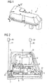
- a machine ( FIG. 1 ) comprises a housing 1 comprising a base 2 and a lid 4.
- the lid 4 and the base 2 are preferably made of a plastic, such.
- a plate 6 is received, which preferably consists of aluminum. The plate 6 rests on the base part 2.
- a frame element 8 is introduced into the housing, which comprises a support leg 10, at least one bending arm 12 and a receiving area 14.
- the frame member 8 preferably comprises as a material also plastic, in particular a thermoplastic material, such. PBT GF30.
- the frame member 8 has in this embodiment a plurality of support legs 10, with which it is supported on the plate 6. It is preferably placed on the plate 6 with the support legs 10.
- the receiving region 14 is designed to accommodate components such as a choke coil 20 and a capacitor 22.
- a punched grid 16 may be introduced for electrically contacting the components which are located on the receiving area.
- the bending arm 12 is formed so that it is elastically bent when placing the lid 4 thereof and so on an inner wall 34 of the lid in a contact region 36 of the bending arm with a contact portion 38 of the lid 4 under bias in contact, namely when the lid 4 with a contact region 32 of the lid 4 in abutment against a contact region 30 of the base part 2.
- the material of the bending arm 12 and its geometry are chosen to ensure an elastic bending of the bending arm on the one hand and on the other hand to ensure that it has sufficient mechanical stability to materially connected to the cover 4 in a finished state of the device mechanical loads on the frame member 8 to stop, caused by acceleration forces acting on the device and depend on the masses of the mounted on the frame member 8 in its receiving area 14 components.
- a plurality of bending arms are formed in the frame member 8, such.
- two bending arms 12 are shown.
- a circuit board 24 is arranged in the housing, which is for example also designed as a flex foil and on the other components 26, 28 are added, which may be, for example, electrical or electronic components or integrated circuits or the like.
- the bending arm 12 has a nose 40 formed on the contact portion 36 of the bending arm. Furthermore, it has a shield body 42, which faces away from the contact region 38 of the cover with respect to the contact region 36 of the bending arm 12 and which in alignment with the contact region 38 of the cover 4 extends beyond the contact region 36 of the bending arm 12.
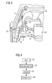
- a program is started in a step S1.
- the frame member 12 is manufactured.
- the stamped grid 16 is at least partially introduced into the receiving region 14 of the frame element.
- the frame element is preferably made of a plastic, which is formed at least in the contact region 36 of the bending arm of a material which absorbs laser radiation of a predetermined wavelength.
- the material In this case, it is selected so that it can subsequently be joined in a material-locking manner with a suitably chosen material of the cover 4 in the contact region 38 of the cover as part of a radiation laser welding step.
- Suitable materials for this purpose are known, for example, from the Internet publication of BASF AG "Laser Beam Welding of Thermoplastics by Transmission Method, Technical Information for Experts 02/00", which was already cited above.
- the components are arranged on the receiving region 14 and optionally electrically contacted, such. B. with the punched grid 16.
- the frame member 8 is inserted into the housing 1 in such a way that it is supported with the support leg 10 on the plate 6. This is done with not yet placed cover 4.
- the plate 6 may, but need not necessarily be present.
- a step S4 the lid 4 is then placed on the base 2 so that the abutment portion 30 of the base 2 is in contact with the abutment portion 32 of the lid 4.
- the bending arm 12 is then elastically bent and contacted with its contact area 36 the contact portion 38 of the lid 4, this being done under a predetermined bias.
- a step S6 the cover 4 is held by means of a pressing device, not shown, which is preferably in the form of a mask, in its abutment with the abutment portion 30 of the base 2 and first and second laser beams 44, 46 are aligned with the abutment portions 30, 32nd or the contact areas 36, 38 brought from the outside on the lid 4 for acting.
- a pressing device not shown, which is preferably in the form of a mask
- the joining process in laser beam welding relies on the conversion of radiant energy to heat by absorption of the material in the abutment region 30 of the base 2 and the contact region 36 of the bending arm 12, suitably selected according to the wavelength of the first and second laser beams 44, 46, respectively.
- the corresponding material of the cover 4 in the abutment region 32 and the contact region 38 of the lid 4 is tuned accordingly, on the one hand to the wavelength of the respective laser beam 44, 46 and also to the corresponding material with which a joining is to take place.
- Corresponding material combinations are also disclosed in the above publication for laser beam welding, the contents of which are hereby incorporated in this regard.
- first and second laser sources 48, 50 are provided for generating the respective laser beams 44, 46.
- the laser radiation is preferably short-wave infrared radiation.
- the respective laser beam 44, 46 penetrates the cover 4, which is transparent to the respective wavelength of the laser beam 44, 46 and is subsequently absorbed in the abutment region 30 of the base part 2 or the contact region 36 of the bending arm 12 and thus converted into heat. This leads to a local melting of the material in the abutment region 30 of the base part 2 and the contact region 36 of the bending arm 12. Due to the contact between the abutment regions 30, 32 or the contact regions 36, 38, heat is also transferred to the cover 4 and leads thus also there to a local melting of the material. This then ultimately leads to a cohesive connection between the lid 4 and the base 2 and between the lid 4 and the bending arm 12th
- the welding in step S6 preferably takes the form of simultaneous welding, in which the laser beams are deflected at high speed over the entire region to be welded.
- the base part 2 with the lid 4 is circumferentially welded to the base or the lid 2, 4.
- several existing bending arms are then welded simultaneously with the lid. This has the advantage that a very homogeneous sinking of the lid 4 down to the base 2 can take place.
- the cover 4 and the base 2 relative to the lid 4 and the bending arm 12 can be welded offset in time. Welding does not necessarily have to be done as part of simultaneous welding.
- the space available within the housing 1 can be so completely filled by the components and there must be no space for an otherwise otherwise successful mechanical fastening of the frame member 8 to the housing by means of fastening means, such as a screw, are provided. This may also result in an accessibility aspect for corresponding tools for attaching the fasteners to more space for the components within the housing 1.
- fastening means such as a screw
Landscapes
- Physics & Mathematics (AREA)
- Engineering & Computer Science (AREA)
- Mechanical Engineering (AREA)
- Electromagnetism (AREA)
- Optics & Photonics (AREA)
- Health & Medical Sciences (AREA)
- Toxicology (AREA)
- Fluid Mechanics (AREA)
- Transportation (AREA)
- Lining Or Joining Of Plastics Or The Like (AREA)
- Laser Beam Processing (AREA)
- Bending Of Plates, Rods, And Pipes (AREA)
Description
- Die Erfindung betrifft ein Gerät und ein Verfahren zum Herstellen eines Geräts mit einem Gehäuse und mit einem Rahmenelement, das innerhalb des Gehäuses angeordnet ist und das mindestens ein Bauelement aufnimmt. Ein derartiges Gerät kann beispielsweise eine Steuervorrichtung für eine Brennkraftmaschine oder auch eine Steuervorrichtung für eine elektrisch stellbare Bremse eines Fahrzeugs sein, die einen elektromotorischen Stellantrieb nutzt, um eine Bremskraft zu erzeugen, die den jeweiligen Bremsen an Rädern eines Fahrzeugs zugeführt wird.
- Aufgrund des häufig nur geringen zur Verfügung stehenden Bauraums für das Gerät, ist es eine Herausforderung, das Gerät möglichst kompakt auszubilden.
- http://www.basf.de/basf/img/dienstl/bauteil/images/laserstrah lschweissen.pdf ist eine technische Information zum Laserstrahlschweißen von Thermoplasten im Durchstrahlverfahren elektronisch abrufbar. Aus dem Dokument ist es bekannt, dass der Fügeprozess beim Laserstrahlschweißen auf der Umwandlung von Strahlungsenergie in Wärme durch Absorption in dem entsprechenden Material führt und dadurch eine lokal begrenzte Schmelze in der Fügezone gebildet wird. Eine kurzwellige Infrarotstrahlung soll das obere transmittierende Fügeteil möglichst ungehindert durchdringen und in einem unteren Fügeteil in einer Tiefe von 0,1 bis 0,5 mm vollständig absorbiert und in Wärme umgewandelt werden. Durch den Energieeintrag wird das untere Fügeteil im Bereich der Absorption erwärmt und aufgeschmolzen. Die Schmelzbildung bewirkt einen Wärmeübertrag zwischen den beiden Fügeteilen und so wird auch das für die Laserstrahlung durchlässige Fügeteil aufgeschmolzen. Die Intensität der Absorption wird sowohl von dem gewählten Werkstoff und seinen Zusätzen als auch von der Wellenlänge der Strahlungsquelle bestimmt.
- Die Aufgabe der Erfindung ist es gemäß eines ersten Aspekts, ein Verfahren zum Herstellen eines Geräts zu schaffen, mittels dessen einfach ein kompaktes Gerät hergestellt werden kann. Die Aufgabe der Erfindung ist es gemäß eines zweiten Aspekts, ein Gerät zu schaffen, das kompakt ist.
- Die Erfindung zeichnet sich gemäß eines ersten Aspekts aus durch ein Verfahren zum Herstellen eines Geräts mit einem Gehäuse und einem Rahmenelement, das innerhalb des Gehäuses angeordnet ist, das mindestens ein Bauelement, insbesondere ein elektrisches oder elektronische Bauelement, aufnimmt und das mindestens einen Biegearm aufweist. Der Biegearm wird so ausgebildet, dass ein Kontaktbereich des Biegearms in einem, insbesondere frei, montierten Zustand innerhalb des Gehäuses an einem Kontaktbereich einer Wandung des Gehäuses mit Vorspannung anliegt. Der Biegearm ist dazu bevorzugt elastisch biegbar und so ausgebildet, dass er in dem frei montierten Zustand innerhalb des Gehäuses elastisch ausgelenkt wird durch eine Wandung des Gehäuses und somit dieser mit Vorspannung anliegt.
- Der Biegearm wird mittels Durchstrahllaserschweißens stoffschlüssig mit dem Gehäuse verbunden und wird durch Beaufschlagen des Geräts mit einem Laserstrahl vorgegebener Wellenlänge derart, dass der Laserstrahl durch das Gehäuse hin zu dem Kontaktbereich des Biegearms transmittiert wird. Das Gehäuse wird zumindest in einem Bereich, durch den der Laserstrahl transmittiert wird, aus einem Material hergestellt, das transparent ist für die vorgegebene Wellenlänge des Laserstrahls. Der Kontaktbereich des Biegearms wird aus einem Material hergestellt, das absorbierend ist für die vorgegebene Wellenlänge des Laserstrahls. Das Verfahren zeichnet sich dadurch aus, dass das Gerät besonders kompakt ausgebildet werden kann und gleichzeitig auch ein zuverlässiges Fixieren des Rahmenelements einfach möglich ist, auch wenn es vollständig von dem Gehäuse umschlossen ist. Durch das Anliegen des Kontaktbereichs des Biegearms an der Wandung des Gehäuses mit Vorspannung kann überraschend einfach eine zuverlässige und hochwertige Schweißverbindung gewährleistet werden.
- Gemäß einer vorteilhaften Ausgestaltung des Verfahrens wird der Biegearm so elastisch ausgebildet, dass er mit einer vorgegebenen Vorspannung in dem montierten Zustand an dem Kontaktbereich des Gehäuses anliegt und andererseits steif genug ist, um Schwingungen zu kompensieren, denen das Rahmenelement ausgesetzt ist. So kann zum einen einfach eine sehr hochwertige und zuverlässige Schweißverbindung sichergestellt werden bei einer gleichzeitig geringen Wahrscheinlichkeit einer mechanischen Beschädigung des Rahmenelements während des Betriebs, insbesondere bei einem Einsatz in einem Kraftfahrzeug, bei dem das Gerät hohen Schwingungsbelastungen ausgesetzt sein kann.
- Gemäß einer weiteren vorteilhaften Ausgestaltung des Verfahrens wird an dem Kontaktbereich des Biegearms eine Nase ausgebildet. Auf diese Weise kann sowohl die Vorspannung einfach geeignet eingestellt werden, es kann eine günstige Massenverteilung des beim Durchstrahlschweißen zu schmelzenden Materials einfach erreicht werden und ein im Vergleich zum Nicht-vorhandensein der Nase größerer Bereich zum Schweißen genutzt werden. Dies hat den Vorteil, eine definierte Kontaktkontur ausgebildet ist auch bei unterschiedlicher Biegung des Biegearms. So ist beispielsweise bei einer Teilkugelförmigen Ausbildung der Nase die Kontaktkontur lediglich abhängig von dem Radius der Teilkugel.
- Gemäß einer weiteren vorteilhaften Ausgestaltung des Verfahrens wird ein Schirmkörper an dem Biegearm ausgebildet, der abgewandt ist von dem Kontaktbereich des Gehäuses in Bezug auf den Kontaktbereich des Biegearms und der in der Flucht des Kontaktbereichs des Gehäuses sich über den Kontaktbereich des Biegearms hinaus erstreckt. Auf diese Weise kann bei einer Fehlpositionierung des Laserstrahls die Wahrscheinlichkeit einer Beschädigung des mindestens einen Bauelements signifikant verringert werden. Auf diese Weise kann beim Herstellen eine geringere Ausfallrate gewährleistet werden, insbesondere falls das Rahmenelement mehrere Biegearme aufweist und so auch bei einem inkorrekten Fixieren eines einzelnen Biegearms die Zuverlässigkeit des Geräts einfach gewährleistet werden.
- Gemäß einer weiteren vorteilhaften Ausgestaltung des Verfahrens erfolgt das Durchstrahllaserschweißen in Form des Simultan-Durchstrahllaserschweißens.
- Gemäß eines zweiten Aspekts zeichnet sich die Erfindung aus durch ein Gerät mit einem Gehäuse und einem Rahmenelement, das innerhalb des Gehäuses angeordnet ist, das mindestens ein Bauelement aufnimmt und das mindestens einen Biegearm aufweist, wobei der Biegearm so ausgebildet ist, dass ein Kontaktbereich des Biegearms in einem montierten Zustand innerhalb des Gehäuses an einem Kontaktbereich einer Wandung des Gehäuses mit Vorspannung anliegt. Der mindestens eine Biegearm ist mittels Durchstrahllaserschweißens stoffschlüssig mit dem Gehäuse verbunden. Das Gehäuse ist zumindest in einem Bereich, durch den zum Durchstrahlschweißen ein Laserstrahl transmittiert wird, aus einem Material hergestellt, das transparent ist für die vorgegebene Wellenlänge des Laserstrahls. Ein Kontaktbereich des Biegearms, in dem der Biegearm mit dem Gehäuse verschweißt ist, ist aus einem Material hergestellt, das absorbierend ist für die vorgegebene Wellenlänge des Laserstrahls. Das Gehäuse und seine vorteilhaften Ausgestaltungen korrespondieren zu dem Verfahren zum Herstellen des Gehäuses. Das Gleiche gilt für die Vorteile.
- Ausführungsbeispiele der Erfindung sind im Folgenden anhand der schematischen Zeichnungen erläutert. Es zeigen:
- Figur 1
- ein Gerät,
- Figur 2
- einen Querschnitt durch das Gerät gemäß
Figur 1 längs einer Linie II, II', - Figur 3
- eine dreidimensionale teilweise Schnittdarstellung eines Teils des Geräts gemäß der
Figur 1 und - Figur 4
- ein Ablaufdiagramm des Ablaufs beim Herstellen des Geräts.
- Ein Gerät (
Figur 1 ) umfasst ein Gehäuse 1, das ein Grundteil 2 und einen Deckel 4 umfasst. Der Deckel 4 und das Grundteil 2 sind bevorzugt aus einem Kunststoff hergestellt, so z. B. aus einem thermoplastischen Kunststoff, wie PBT GF30. In dem Gehäuse ist eine Platte 6 aufgenommen, die bevorzugt aus Aluminium besteht. Die Platte 6 liegt auf dem Grundteil 2 auf. - Ferner ist ein Rahmenelement 8 in das Gehäuse eingebracht, das einen Stützfuß 10, mindestens einen Biegearm 12 und einen Aufnahmebereich 14 umfasst. Das Rahmenelement 8 umfasst als Material bevorzugt auch Kunststoff, insbesondere einen thermoplastischen Kunststoff, so z. B. PBT GF30. Das Rahmenelement 8 hat in dieser Ausführungsform mehrere Stützfüße 10, mit denen es auf der Platte 6 abgestützt ist. Es ist bevorzugt auf die Platte 6 mit den Stützfüßen 10 aufgesetzt.
- Der Aufnahmebereich 14 ist ausgebildet zur Aufnahme von Bauelementen, wie einer Drosselspule 20 und einem Kondensator 22. In dem Aufnahmebereich 14 kann auch ein Stanzgitter 16 eingebracht sein zum elektrischen Kontaktieren der Bauelemente, die sich auf dem Aufnahmebereich befinden.
- Der Biegearm 12 ist so ausgebildet, dass er beim Aufsetzen des Deckels 4 elastisch von diesem verbogen wird und so an einer inneren Wandung 34 des Deckels dann in einem Kontaktbereich 36 des Biegearms mit einem Kontaktbereich 38 des Deckels 4 unter Vorspannung in Kontakt ist, und zwar dann, wenn der Deckel 4 mit einem Anlagebereich 32 des Deckels 4 in Anlage an einem Anlagebereich 30 des Grundteils 2 ist. Das Material des Biegearms 12 und seine Geometrie sind entsprechend gewählt, um ein elastisches Verbiegen des Biegearms zum einen zu gewährleisten und zum anderen sicherzustellen, dass er eine ausreichende mechanische Stabilität hat, um in einem fertig hergestellten Zustand des Geräts stoffschlüssig mit dem Deckel 4 verbundenen Zustand mechanischen Belastungen des Rahmenelements 8 stand zu halten, hervorgerufen durch Beschleunigungskräfte, die auf das Gerät einwirken und abhängen von den Massen der auf dem Rahmenelement 8 in seinem Aufnahmebereich 14 befestigten Bauelementen.
- Bevorzugt sind mehrere Biegearme in dem Rahmenelement 8 ausgebildet, so z. B. zwei oder beliebig mehrere Biegearme 12. In dem Schnitt gemäß der
Figur 3 sind beispielsweise zwei Biegearme 12 dargestellt. - Ferner ist in dem Gehäuse auch noch eine Leiterplatte 24 angeordnet, die beispielsweise auch als Flexfolie ausgebildet ist und auf der weitere Bauelemente 26, 28 aufgenommen sind, die beispielsweise elektrische oder elektronische Bauelemente oder auch integrierte Schaltkreise oder dergleichen sein können.
- Der Biegearm 12 hat eine Nase 40, die an dem Kontaktbereich 36 des Biegearms ausgebildet ist. Ferner hat er einen Schirmkörper 42, der abgewandt ist von dem Kontaktbereich 38 des Deckels in Bezug auf den Kontaktbereich 36 des Biegearms 12 und der in der Flucht des Kontaktbereichs 38 des Deckels 4 sich über den Kontaktbereich 36 des Biegearms 12 hinaus erstreckt.
- Im Folgenden wird das Vorgehen beim Herstellen anhand des Ablaufdiagramms der
Figur 4 näher erläutert. Ein Programm wird in einem Schritt S1 gestartet. - In einem Schritt S2 wird das Rahmenelement 12 hergestellt. Dazu wird das Stanzgitter 16 zumindest teilweise in den Aufnahmebereich 14 des Rahmenelements eingebracht. Dies kann beispielsweise erfolgen durch Kunststoffspritzen des Rahmenelements. Das Rahmenelement wird bevorzugt aus einem Kunststoff hergestellt, der zumindest in dem Kontaktbereich 36 des Biegearms aus einem Material ausgebildet ist, das Laserstrahlung einer vorgegebenen Wellenlänge absorbiert. Das Material ist dabei so ausgewählt, dass es nachfolgend im Rahmen eines Durchstrahllaserschweißschrittes stoffschlüssig mit einem ebenfalls geeignet gewählten Material des Deckels 4 in dem Kontaktbereich 38 des Deckels stoffschlüssig verbunden werden kann. Geeignete Materialien für diesen Zweck sind beispielsweise aus der Internetveröffentlichung der BASF AG "Laserstrahlschweißen von Thermoplasten im Durchstrahlverfahren, Technische Information für Experten 02/00", die bereits eingangs zitiert wurde, bekannt.
- Ferner werden in dem Schritt S2 die Bauelemente auf dem Aufnahmebereich 14 angeordnet und gegebenenfalls elektrisch kontaktiert, so z. B. mit dem Stanzgitter 16. Anschließend wird das Rahmenelement 8 in das Gehäuse 1 eingesetzt und zwar so, dass es sich mit dem Stützfuß 10 auf der Platte 6 abstützt. Dies erfolgt bei noch nicht aufgesetztem Deckel 4. Die Platte 6 kann, muss jedoch nicht notwendigerweise vorhanden sein.
- In einem Schritt S4 wird dann anschließend der Deckel 4 auf das Grundteil 2 so aufgesetzt, dass der Anlagebereich 30 des Grundteils 2 in Kontakt ist mit dem Anlagebereich 32 des Deckels 4. In diesem Zustand ist dann der Biegearm 12 elastisch verbogen und kontaktiert mit seinem Kontaktbereich 36 den Kontaktbereich 38 des Deckels 4, wobei dies unter einer vorgegebenen Vorspannung erfolgt.
- In einem Schritt S6 wird der Deckel 4 mittels einer nicht dargestellten Pressvorrichtung, die bevorzugt in Form einer Maske ausgebildet ist, in seiner Anlage mit dem Anlagebereich 30 des Grundteils 2 gehalten und erste und zweite Laserstrahlen 44, 46 werden fluchtend zu den Anlagebereichen 30, 32 bzw. den Kontaktbereichen 36, 38 von außen auf den Deckel 4 zum Einwirken gebracht. In diesem Schritt erfolgt somit das Durchstrahllaserschweißen, das im Folgenden näher erläutert ist.
- Der Fügeprozess beim Laserstrahlschweißen beruht auf der Umwandlung von Strahlungsenergie in Wärme durch Absorption des Materials in dem Anlagebereich 30 des Grundteils 2 bzw. dem Kontaktbereich 36 des Biegearms 12, das entsprechend der Wellenlänge des ersten bzw. zweiten Laserstrahls 44, 46 geeignet ausgewählt ist. Darüber hinaus ist auch das korrespondierende Material des Deckels 4 in dem Anlagebereich 32 und dem Kontaktbereich 38 des Deckels 4 entsprechend abgestimmt, zum einen auf die Wellenlänge des jeweiligen Laserstrahls 44, 46 und auch auf das korrespondierende Material, mit dem ein Fügen erfolgen soll. Entsprechende Materialkombinationen sind ebenfalls in der oben genannten Veröffentlichung zum Laserstrahlschweißen offenbart, deren Inhalt hiermit diesbezüglich einbezogen ist.
- Bevorzugt sind erste und zweite Laserquellen 48, 50 zum Erzeugen der jeweiligen Laserstrahlen 44, 46 vorgesehen. Bevorzugt handelt es sich bei der Laserstrahlung um kurzwellige Infrarotstrahlung. Der jeweilige Laserstrahl 44, 46 durchdringt den Deckel 4, der transparent ist für die jeweilige Wellenlänge des Laserstrahls 44, 46 und wird anschließend in dem Anlagebereich 30 des Grundteils 2 bzw. dem Kontaktbereich 36 des Biegearms 12 absorbiert und so in Wärme umgewandelt. Dies führt zu einem lokalen Aufschmelzen des Materials in dem Anlagebereich 30 des Grundteils 2 und dem Kontaktbereich 36 des Biegearms 12. Durch den Kontakt zwischen den Anlagenbereichen 30, 32 bzw. den Kontaktbereichen 36, 38 erfolgt eine Wärmeübertragung auch hin zu dem Deckel 4 und führt somit auch dort zu einem lokalen Aufschmelzen des Materials. Dies führt dann letztlich zu einer stoffschlüssigen Verbindung zwischen dem Deckel 4 und dem Grundteil 2 bzw. zwischen dem Deckel 4 und dem Biegearm 12.
- Bevorzugt erfolgt das Schweißen in dem Schritt S6 in Form des Simultanschweißens, bei dem die Laserstrahlen mit hoher Geschwindigkeit über den gesamten zu verschweißenden Bereich umlaufend ausgelenkt werden. Bevorzugt wird das Grundteil 2 mit dem Deckel 4 umlaufend um das Grundteil bzw. den Deckel 2, 4 verschweißt. Darüber hinaus werden dann auch die gegebenenfalls mehreren vorhandenen Biegearme simultan mit dem Deckel verschweißt. Dies hat den Vorteil, dass ein sehr homogenes Einsinken des Deckels 4 hinunter zu dem Grundteil 2 erfolgen kann. Alternativ können jedoch auch der Deckel 4 und das Grundteil 2 gegenüber dem Deckel 4 und dem Biegearm 12 zeitlich versetzt verschweißt werden. Das Schweißen muss auch nicht notwendigerweise im Rahmen des Simultanschweißens erfolgen.
- Durch das Vorsehen des Schirmkörpers 42 kann einfach auch bei einer gegebenenfalls etwas ungenauen Positionierung des Laserstrahls 46 verhindert werden, dass durch diesen Bauteile innerhalb des Gehäuses 1 beschädigt werden.
- Der innerhalb des Gehäuses 1 zur Verfügung stehende Bauraum kann so sehr vollständig durch die Bauelemente ausgefüllt werden und es müssen keine Freiräume für ein gegebenenfalls ansonsten erfolgendes mechanisches Befestigen des Rahmenelements 8 an dem Gehäuse mittels Befestigungsmitteln, wie einer Schraube, vorgesehen werden. Dies kann auch zu einem Gesichtspunkt der Zugänglichkeit für entsprechende Werkzeuge zum Befestigen der Befestigungsmittel zu mehr für die Bauelemente nutzbaren Raum innerhalb des Gehäuses 1 führen. Durch das Ausbilden der Nase 40 an dem Kontaktbereich 36 des Biegearms 12 kann ebenfalls bei der Positioniergenauigkeit des zweiten Laserstrahls 46 eine höhere Toleranz in Kauf genommen werden, ohne die Güte des Fügeprozesses signifikant zu beeinflussen. Der Biegearm 12 kann auch an einer oder mehreren anderen Stellen stoffschlüssig mit dem Deckel oder auch mit dem Grundteil 2 verbunden sein. Das Schweißen kann auch als so genanntes Maskenschweißen durchgeführt werden, wie es ebenfalls in der BASF-Veröffentlichung offenbart ist.
Claims (6)
- Verfahren zum Herstellen eines Geräts mit einem Gehäuse(1) und einem Rahmenelement (8), das innerhalb des Gehäuses (1) angeordnet ist, das mindestens ein Bauelement aufnimmt und das mindestens einen Biegearm (12) aufweist, bei dem- der Biegearm (12) so ausgebildet wird, dass ein Kontaktbereich (36) des Biegearms (12) in einem montierten Zustand innerhalb des Gehäuses (1) an einem Kontaktbereich (38) einer Wandung (34) des Gehäuses (1) mit Vorspannung anliegt, und- der Biegearm (12) mittels Durchstrahllaserschweißens stoffschlüssig mit dem Gehäuse (1) verbunden wird durch Beaufschlagen des Geräts mit einem Laserstrahl (44, 46) vorgegebener Wellenlänge derart, dass der Laserstrahl (46) durch das Gehäuse (1) hin zu dem Kontaktbereich (36) des Biegearms (12) transmittiert wird, wobei das Gehäuse (1) zumindest in einem Bereich, in den der Laserstrahl (46) transmittiert wird, aus einem Material hergestellt wird, das transparent ist für die vorgegebene Wellenlänge des Laserstrahl (46), und der Kontaktbereich (36) des Biegearms (12) aus einem Material hergestellt wird, das absorbierend ist für die vorgegebene Wellenlänge des Laserstrahls (46).
- Verfahren nach Anspruch 1, bei dem der Biegearm (12) so elastisch ausgebildet wird, dass er mit einer vorgegebenen Vorspannung in dem montierten Zustand an dem Kontaktbereich (38) des Gehäuses (1) anliegt und andererseits steif genug ist, um Schwingungen zu kompensieren, denen das Rahmenelement (8) ausgesetzt ist.
- Verfahren nach einem der vorstehenden Ansprüche, bei dem an dem Kontaktbereich (36) des Biegearms (12) eine Nase (40) ausgebildet wird.
- Verfahren nach einem der vorstehenden Ansprüche, bei dem ein Schirmkörper (42) an dem Biegearm (12) ausgebildet wird, der abgewandt ist von dem Kontaktbereich (38) des Gehäuses (1) in Bezug auf den Kontaktbereich (36) des Biegearms (12) und der in der Flucht des Kontaktbereichs (38) des Gehäuses (1) sich über den Kontaktbereich (36) des Biegearms (12) hinaus erstreckt.
- Verfahren nach einem der vorstehenden Ansprüche, bei dem das Durchstrahllaserschweißen in Form des SimultanDurchstrahllaserschweißens erfolgt.
- Gerät mit einem Gehäuse (1) und einem Rahmenelement (8), das innerhalb des Gehäuses (1) angeordnet ist, das mindestens ein Bauelement aufnimmt und das mindestens einen Biegearm aufweist, wobei- der Biegearm (12) so ausgebildet ist, dass ein Kontaktbereich (36) des Biegearms (12) in einem montierten Zustand innerhalb des Gehäuses (1) an einem Kontaktbereich (38) einer Wandung (34) des Gehäuses (1) mit Vorspannung anliegt und- der Biegearm (12) mittels Durchstrahllaserschweißens stoffschlüssig mit dem Gehäuse (1) verbunden ist, wobei das Gehäuse (1) zumindest in einem Bereich, durch den zum Durchstrahllaserschweißen ein Laserstrahl vorgegebener Wellenlänge transmittiert wird, aus einem Material hergestellt ist, das transparent ist für die vorgegebene wellenlänge des Laserstrahls (46), und ein Kontaktbereich (36) des Biegearms (12), in dem der Biegearm (12) mit dem Gehäuse (1) verschweißt ist, aus einem Material hergestellt ist, das absorbierend ist für die vorgegebene Wellenlänge des Laserstrahls (46).
Applications Claiming Priority (2)
| Application Number | Priority Date | Filing Date | Title |
|---|---|---|---|
| DE102005026205A DE102005026205B3 (de) | 2005-06-07 | 2005-06-07 | Gerät und Verfahren zum Herstellen eines Geräts |
| PCT/EP2006/062865 WO2006131499A1 (de) | 2005-06-07 | 2006-06-02 | Gerät und verfahren zum herstellen eines geräts |
Publications (2)
| Publication Number | Publication Date |
|---|---|
| EP1899143A1 EP1899143A1 (de) | 2008-03-19 |
| EP1899143B1 true EP1899143B1 (de) | 2009-01-21 |
Family
ID=36950838
Family Applications (1)
| Application Number | Title | Priority Date | Filing Date |
|---|---|---|---|
| EP06763486A Not-in-force EP1899143B1 (de) | 2005-06-07 | 2006-06-02 | Gerät und verfahren zum herstellen eines geräts |
Country Status (5)
| Country | Link |
|---|---|
| US (1) | US7868259B2 (de) |
| EP (1) | EP1899143B1 (de) |
| JP (1) | JP4638941B2 (de) |
| DE (2) | DE102005026205B3 (de) |
| WO (1) | WO2006131499A1 (de) |
Families Citing this family (8)
| Publication number | Priority date | Publication date | Assignee | Title |
|---|---|---|---|---|
| DE102007021268A1 (de) * | 2007-05-03 | 2008-11-06 | Brose Fahrzeugteile Gmbh & Co. Kommanditgesellschaft, Hallstadt | Verfahren zur Montage einer Verstelleinheit für ein Kraftfahrzeug und hiermit herstellbare Verstelleinheit |
| DE102007028789B4 (de) * | 2007-06-22 | 2021-12-16 | Fraunhofer-Gesellschaft zur Förderung der angewandten Forschung e.V. | Verfahren zum Fügen von Hybridbauteilen und dadurch hergestelltes Hybridbauteil |
| DE102008038018A1 (de) * | 2008-08-11 | 2010-02-18 | Elringklinger Ag | Baugruppe aus miteinander verschweißten Kunststoffteilen sowie Verfahren zu ihrer Herstellung |
| DE102011081638A1 (de) * | 2011-08-26 | 2013-02-28 | Zf Friedrichshafen Ag | Gehäuseteil für ein Gehäuse eines Sensors für ein Fahrzeuggetriebe, Gehäuse für einen Sensor für ein Fahrzeuggetriebe, Sensor für ein Fahrzeuggetriebe und Verfahren zum Herstellen eines Sensors für ein Fahrzeuggetriebe |
| KR101606670B1 (ko) * | 2015-06-22 | 2016-03-25 | 효성전기주식회사 | 레이저 융착방식으로 결합되는 moc 액츄에이터 |
| DE102016218177A1 (de) | 2016-09-21 | 2018-03-22 | Brose Fahrzeugteile Gmbh & Co. Kommanditgesellschaft, Bamberg | Montageverfahren für ein Sensormodul und Sensormodul |
| US10680380B2 (en) * | 2018-09-13 | 2020-06-09 | Aptiv Technologies Limited | Angled electrical connector assembly and method of manufacturing same |
| DE102021132129A1 (de) * | 2021-12-07 | 2023-06-07 | Kiekert Aktiengesellschaft | Stellantrieb für kraftfahrzeugtechnische Anwendungen |
Family Cites Families (14)
| Publication number | Priority date | Publication date | Assignee | Title |
|---|---|---|---|---|
| US5138114A (en) * | 1990-09-27 | 1992-08-11 | Texas Instruments Incorporated | Hybrid/microwave enclosures and method of making same |
| US5250845A (en) * | 1990-11-30 | 1993-10-05 | Hughes Aircraft Company | Totally enclosed hermetic electronic module |
| US5365108A (en) * | 1992-11-19 | 1994-11-15 | Sundstrand Corporation | Metal matrix composite semiconductor power switch assembly |
| DE19921928C2 (de) * | 1999-05-12 | 2002-11-14 | Bosch Gmbh Robert | Elektrisches Gerät |
| DE10005978B4 (de) * | 2000-02-09 | 2014-12-04 | Continental Automotive Gmbh | Anzeigeinstrument und Verfahren zum Verbinden einer Leiterplatte eines Anzeigeinstrumentes mit einem Einzeladern aufweisenden Anschlußkabel |
| DE60135405D1 (de) * | 2000-03-21 | 2008-10-02 | Autonetworks Technologies Ltd | Leistungsverteiler für ein Kraftfahrzeug und Verfahren zur Herstellung dazu |
| EP1201505B1 (de) * | 2000-10-26 | 2006-12-06 | Sumitomo Wiring Systems, Ltd. | Elektrische Kraftfahrzeugverbindungsdose |
| JP2002160537A (ja) * | 2000-11-24 | 2002-06-04 | Toyota Motor Corp | 樹脂製燃料タンク |
| JP3753024B2 (ja) * | 2001-07-09 | 2006-03-08 | 株式会社デンソー | 突き合わせレーザー溶着方法 |
| JP4042439B2 (ja) * | 2002-03-18 | 2008-02-06 | トヨタ自動車株式会社 | レーザ溶着された組立体 |
| DE10336263A1 (de) * | 2003-08-07 | 2005-03-10 | Bosch Gmbh Robert | Verfahren sowie Gestaltung der Fügezone zur Einstellung einer Position von Kunststoffteilen für eine stoffschlüssige Verbindung der Bauteile |
| JP2005085567A (ja) * | 2003-09-08 | 2005-03-31 | Koito Mfg Co Ltd | 車両用灯具 |
| US7186912B2 (en) * | 2003-09-26 | 2007-03-06 | Avanex Corporation | Hermetic lid seal by metal pressing for fiber optic module |
| FR2913530B1 (fr) * | 2007-03-09 | 2009-06-05 | Accumulateurs Fixes | Terminal electrique pour accumulateur etanche. |
-
2005
- 2005-06-07 DE DE102005026205A patent/DE102005026205B3/de not_active Expired - Fee Related
-
2006
- 2006-06-02 WO PCT/EP2006/062865 patent/WO2006131499A1/de not_active Ceased
- 2006-06-02 EP EP06763486A patent/EP1899143B1/de not_active Not-in-force
- 2006-06-02 US US11/921,833 patent/US7868259B2/en not_active Expired - Fee Related
- 2006-06-02 JP JP2008515204A patent/JP4638941B2/ja not_active Expired - Fee Related
- 2006-06-02 DE DE502006002726T patent/DE502006002726D1/de active Active
Also Published As
| Publication number | Publication date |
|---|---|
| EP1899143A1 (de) | 2008-03-19 |
| US7868259B2 (en) | 2011-01-11 |
| US20100136818A1 (en) | 2010-06-03 |
| DE502006002726D1 (de) | 2009-03-12 |
| JP2008545563A (ja) | 2008-12-18 |
| DE102005026205B3 (de) | 2006-10-05 |
| WO2006131499A1 (de) | 2006-12-14 |
| JP4638941B2 (ja) | 2011-02-23 |
Similar Documents
| Publication | Publication Date | Title |
|---|---|---|
| EP2480396A1 (de) | Verfahren zum verschweissen eines kunststoffgehäuses | |
| DE102010001493A1 (de) | Verfahren zur Fixierung eines Bauelements in einem Gehäuse und Anordnung daraus | |
| DE102005026205B3 (de) | Gerät und Verfahren zum Herstellen eines Geräts | |
| WO2015197713A1 (de) | Sensormodul und verfahren zum herstellen eines sensormoduls | |
| DE10256254B4 (de) | Verfahren zum Verschweißen | |
| DE102008039921A1 (de) | Elektronisches Gerät mit diskretem Bauelement und Verfahren zur Herstellung desselben | |
| DE102014205015B4 (de) | Verfahren zum Verbinden zweier elektrisch leitender Bauteile mittels eines Laserstrahls und Bauteileverbund | |
| DE102013204149A1 (de) | Verfahren zum Herstellen einer modularen elektrischen Steckerverbinderanordnung für ein Steuergerät in einem Kraftfahrzeug | |
| DE102020211245A1 (de) | Verfahren zur Herstellung einer elektromechanischen Baugruppe, Baugruppe und Steuergerät | |
| EP0299136A2 (de) | Verfahren zur Herstellung einer Schaltungsplatte | |
| WO2011035771A1 (de) | Verfahren zum verschweissen eines kunststoffgehäuses | |
| WO1997008925A1 (de) | Verfahren zur herstellung einer verbindung zwischen zumindest zwei elektrischen leitern, von denen einer auf einem trägersubstrat angeordnet ist | |
| DE10227495A1 (de) | Verfahren zum Verbinden zweier Bauteile | |
| DE102017106635A1 (de) | Verfahren zur Verbindung von drei Bauteilen und verbindbares System zur Durchführung des Verfahrens | |
| EP1051887B1 (de) | Verfahren zur herstellung eines ein elektronikbauteil enthaltenden kunststoffobjektes | |
| EP1468313A2 (de) | Haltevorrichtung für die anordnung eines optischen bauteils vor einer laserlichtquelle | |
| DE102014010023B4 (de) | Verfahren und Vorrichtung zur Verbindung von zwei Bauteilen eines elektrischen Anschlussteils | |
| WO2015090970A1 (de) | Verfahren zur montage einer chipträger-led auf einen trägerkörper und optoelektronisches bauelement mit einer chipträger-led und einem trägerkörper | |
| DE10220761A1 (de) | Elektronischer Sensor mit elektronischen Sensorbauelementen und Verfahren zu dessen Herstellung | |
| DE102012108859B4 (de) | Elektronikmodul | |
| DE102010028621A1 (de) | Verfahren zur Herstellung einer Getriebesteuerungseinheit | |
| EP2653018B1 (de) | Steuergerät und verfahren zum herstellen eines steuergeräts | |
| DE102013226641A1 (de) | Verfahren zur Montage einer Baugruppe, Baugruppe und Verwendung einer Vorrichtung zum Montieren von Baugruppen | |
| DE102017221543A1 (de) | Leiterplattennutzen | |
| DE102022103523A1 (de) | Verfahren zur Herstellung einer Kraftfahrzeugbaugruppe und Kraftfahrzeugbaugruppe |
Legal Events
| Date | Code | Title | Description |
|---|---|---|---|
| PUAI | Public reference made under article 153(3) epc to a published international application that has entered the european phase |
Free format text: ORIGINAL CODE: 0009012 |
|
| 17P | Request for examination filed |
Effective date: 20071108 |
|
| AK | Designated contracting states |
Kind code of ref document: A1 Designated state(s): DE FR GB |
|
| RAP1 | Party data changed (applicant data changed or rights of an application transferred) |
Owner name: VDO AUTOMOTIVE AG |
|
| GRAP | Despatch of communication of intention to grant a patent |
Free format text: ORIGINAL CODE: EPIDOSNIGR1 |
|
| RBV | Designated contracting states (corrected) |
Designated state(s): DE FR GB |
|
| RAP1 | Party data changed (applicant data changed or rights of an application transferred) |
Owner name: CONTINENTAL AUTOMOTIVE GMBH |
|
| DAX | Request for extension of the european patent (deleted) | ||
| GRAS | Grant fee paid |
Free format text: ORIGINAL CODE: EPIDOSNIGR3 |
|
| GRAA | (expected) grant |
Free format text: ORIGINAL CODE: 0009210 |
|
| AK | Designated contracting states |
Kind code of ref document: B1 Designated state(s): DE FR GB |
|
| REG | Reference to a national code |
Ref country code: GB Ref legal event code: FG4D Free format text: NOT ENGLISH |
|
| REF | Corresponds to: |
Ref document number: 502006002726 Country of ref document: DE Date of ref document: 20090312 Kind code of ref document: P |
|
| PLBE | No opposition filed within time limit |
Free format text: ORIGINAL CODE: 0009261 |
|
| STAA | Information on the status of an ep patent application or granted ep patent |
Free format text: STATUS: NO OPPOSITION FILED WITHIN TIME LIMIT |
|
| 26N | No opposition filed |
Effective date: 20091022 |
|
| PGFP | Annual fee paid to national office [announced via postgrant information from national office to epo] |
Ref country code: DE Payment date: 20120630 Year of fee payment: 7 |
|
| PGFP | Annual fee paid to national office [announced via postgrant information from national office to epo] |
Ref country code: GB Payment date: 20130619 Year of fee payment: 8 |
|
| PGFP | Annual fee paid to national office [announced via postgrant information from national office to epo] |
Ref country code: FR Payment date: 20130703 Year of fee payment: 8 |
|
| REG | Reference to a national code |
Ref country code: DE Ref legal event code: R119 Ref document number: 502006002726 Country of ref document: DE Effective date: 20140101 |
|
| PG25 | Lapsed in a contracting state [announced via postgrant information from national office to epo] |
Ref country code: DE Free format text: LAPSE BECAUSE OF NON-PAYMENT OF DUE FEES Effective date: 20140101 |
|
| GBPC | Gb: european patent ceased through non-payment of renewal fee |
Effective date: 20140602 |
|
| REG | Reference to a national code |
Ref country code: FR Ref legal event code: ST Effective date: 20150227 |
|
| PG25 | Lapsed in a contracting state [announced via postgrant information from national office to epo] |
Ref country code: GB Free format text: LAPSE BECAUSE OF NON-PAYMENT OF DUE FEES Effective date: 20140602 Ref country code: FR Free format text: LAPSE BECAUSE OF NON-PAYMENT OF DUE FEES Effective date: 20140630 |