EP1898103A2 - Hydraulic cylinder with automatic locking - Google Patents
Hydraulic cylinder with automatic locking Download PDFInfo
- Publication number
- EP1898103A2 EP1898103A2 EP07291000A EP07291000A EP1898103A2 EP 1898103 A2 EP1898103 A2 EP 1898103A2 EP 07291000 A EP07291000 A EP 07291000A EP 07291000 A EP07291000 A EP 07291000A EP 1898103 A2 EP1898103 A2 EP 1898103A2
- Authority
- EP
- European Patent Office
- Prior art keywords
- piston
- cylinder
- wall
- pressure
- hydraulic
- Prior art date
- Legal status (The legal status is an assumption and is not a legal conclusion. Google has not performed a legal analysis and makes no representation as to the accuracy of the status listed.)
- Withdrawn
Links
Images

Classifications
-
- F—MECHANICAL ENGINEERING; LIGHTING; HEATING; WEAPONS; BLASTING
- F15—FLUID-PRESSURE ACTUATORS; HYDRAULICS OR PNEUMATICS IN GENERAL
- F15B—SYSTEMS ACTING BY MEANS OF FLUIDS IN GENERAL; FLUID-PRESSURE ACTUATORS, e.g. SERVOMOTORS; DETAILS OF FLUID-PRESSURE SYSTEMS, NOT OTHERWISE PROVIDED FOR
- F15B15/00—Fluid-actuated devices for displacing a member from one position to another; Gearing associated therewith
- F15B15/20—Other details, e.g. assembly with regulating devices
- F15B15/26—Locking mechanisms
- F15B15/262—Locking mechanisms using friction, e.g. brake pads
Definitions
- the present invention relates to a hydraulic cylinder provided with means for locking it at any point of its stroke.
- the known mechanical locking means are expensive and complex.
- the present invention solves the problem of locking a hydraulic cylinder, whatever its position and that as long as necessary.
- the object of the present invention is to provide a jack which is permanently locked and which is unlocked only on command.
- This jack is of the type in which the locking of the piston is obtained by elastic deformation either of the inner wall of the cylinder or of the outer wall of the piston, so as to obtain the tightening of one on the other, and is characterized by the fact that the locking is permanently obtained by means of a pressure, which causes the elastic deformation of the inner wall of the cylinder or the outer wall of the piston; the unlocking of said jack being obtained by canceling this permanent deformation.
- the locking is permanently obtained by the elastic deformation of the cylinder or the piston under the effect of a sealed chamber, permanently filled with a neutral gas under pressure; the unlocking being obtained by a hydraulic pressure which is interposed between the piston and the cylinder so as to exert a counter-pressure counter-pressure which cancels the elastic deformation caused by the neutral gas under pressure.
- the locking is permanently obtained by elastic deformation of the outer wall of the piston under the effect of a hydraulic pressure exerted permanently by a battery, arranged inside. of the piston, the action of this accumulator being suppressed by a mechanical control, which cancels the elastic deformation of the wall of the piston.
- the hydraulic cylinder comprises a piston 1 which moves in a cylinder consisting of two coaxial tubes 2 and 3, which provide a space between them cylindrical ring 4.
- Said annular space 4 is connected to a pressurized gas source 6 through a non-return valve 7; so that the chamber 4 is a closed, sealed volume, the pressure of the gas being permanent.
- the deformation of the inner tube 2 is a function of the thickness of the wall of this tube, the metal used and the pressure of the gas blown into the space 4. These parameters are determined according to the use for which the jack is intended .
- the importance of the locking force of the piston 1 is a function of the pressure of the gas and the importance of the surfaces in contact. These parameters will also be determined according to the use for which the cylinder is intended.
- Figures 4 to 6 relate to an alternative embodiment of the self-locking cylinder.
- the piston 1 carries at each of its ends 25-26 sealing segments similar to the segments used in internal combustion engines.
- sealing segments 25 and 26 are formed two annular grooves 20 and 21, which are connected to each other by a conduit 22, which communicates with the chambers 8 and 9 of the cylinder by the valves -return 23 and 24 in reversed positions.
- the cylindrical annular chamber 4 which is permanently filled with a neutral gas (nitrogen) under pressure, causes the elastic deformation of the inner tube 2, whose wall is relatively thin and deformable.
- the piston 1 is then jammed by the tightening exerted by the pressure of the gas and can no longer move.
- the chamber 8 is fed with hydraulic fluid under pressure through the pipe Pa.
- This liquid pushes back the non-return valve 24 and through the pipe 22 feeds the grooves 20 and 21, which allows the counter-pressure against set up all around the piston 1, to cancel the effect of the gas pressure included in the chamber 4; so that the piston 1 is unlocked and can move in the direction D1.
- the sealing segments 25 and 26 allow one and the other a slight leak at the beginning of pressurization: this leak, adding to the introduction of liquid under pressure by the grooves 20 and 21, facilitates the appearance of a film of oil under pressure between the wall of the piston 1 and that of the tube 2.
- FIGS. 7 to 10 show another embodiment of the invention which operates in an inverse manner, that is to say that it is no longer the cylinder which presses the piston by retracting elastically but the piston which comes to tighten against the wall of the cylinder by expanding.
- Figure 7 illustrates a first locking position of the jack.
- the piston 30, carried by a rod 31, can slide in a cylinder 32.
- the piston is hollow and comprises a chamber 33 filled with a neutral gas under pressure.
- the wall 30a surrounding the chamber 33 is relatively thin and deformable: under the effect of the pressure of the gas in the chamber 33, the wall 30a deforms and is pressed against the inner wall of the cylinder 32; so that the piston is blocked.
- FIG. 8 shows that pressurized hydraulic fluid has been introduced into the chamber 34.
- This hydraulic fluid under pressure is interposed between the wall 30a of the piston 30 and the inner wall of the cylinder 32, creating an antagonistic back pressure which cancels the deformation of said wall 30a, which releases the piston 30 which can move along the arrow f1.
- the hydraulic pressure is introduced into the small chamber 35.
- the hydraulic fluid under pressure is interposed between the wall 30a of the piston 30 and the inner wall of the cylinder 32, creating an antagonistic counter-pressure which cancels the deformation of the said wall 30a, which releases the piston 30 which can move along the arrow f2.
- the chambers 4 or 33 are sealed, permanently pressurized volumes, but a check valve can also be provided. as the valve 7 of Figures 2 and 3 or have one in the pipe 33a, located in the piston rod to cancel the pressure of the gas.
- This type of cylinder will be used in all cases where a cylinder must maintain a load without changing position and this for a very long time.
- such a cylinder can be advantageously used for positioning a mobile radar; so that once the radar is set, its position is kept constant.
- the blocking of the piston is obtained by the fact that the chamber filled with gas is tight and permanently filled with gas under pressure; but it is obvious that one can obtain the unlocking either by canceling the gas pressure by a suitable valve, or by replacing the gas pressure by a gas pressure or variable and controlled fluid.
- Figures 11 and 12 illustrate a third embodiment of the invention.
- the jack is constituted by a cylinder 20, in which slides a piston 21 integral with a rod 22.
- the piston 21 comprises an annular chamber 23 whose annular wall 24, in contact with the inner wall of the cylinder 20 is elastically deformable.
- This annular chamber 23 is in communication with the chamber 25 of an accumulator 26, disposed inside the piston 21.
- a mechanical means consisting of a rod 27 sliding inside the rod 22 of the piston 21 can push the movable member of the accumulator 26 against its spring 29.
- this rod 27 can be caused by any appropriate device; but, in the example shown it is caused by a small piston 28, secured to the rod 27, hydraulically controlled.
Landscapes
- Engineering & Computer Science (AREA)
- Physics & Mathematics (AREA)
- Fluid Mechanics (AREA)
- Mechanical Engineering (AREA)
- General Engineering & Computer Science (AREA)
- Actuator (AREA)
- Braking Arrangements (AREA)
Abstract
Description
La présente invention est relative à un vérin hydraulique muni de moyens permettant de le verrouiller en n'importe quel point de sa course.The present invention relates to a hydraulic cylinder provided with means for locking it at any point of its stroke.
Il est souvent nécessaire de maintenir un vérin hydraulique en position quelle que soit sa charge et cela pendant un temps très long.It is often necessary to maintain a hydraulic cylinder in position whatever its load and for a very long time.
Les moyens de verrouillage mécanique connus sont onéreux et complexes.The known mechanical locking means are expensive and complex.
La présente invention résout le problème du blocage d'un vérin hydraulique, quelle que soit sa position et cela aussi longtemps que nécessaire.The present invention solves the problem of locking a hydraulic cylinder, whatever its position and that as long as necessary.
Dans le brevet
Dans le brevet
Des dispositifs analogues sont décrits dans les brevets
Ces dispositifs ne donnent pas satisfaction lorsqu'il est nécessaire de maintenir un vérin hydraulique en position pendant un temps très long quelle que soit sa charge ; parce qu'il est, dans la pratique, quasiment impossible d'avoir un système hydraulique sans fuite ; de sorte que, à la longue, les vérins décrits plus haut finissent par se débloquer.These devices are unsatisfactory when it is necessary to maintain a hydraulic cylinder in position for a very long time regardless of its load; because in practice it is almost impossible to have a leak-free hydraulic system; so that, in the long run, the cylinders described above end up unlocking.
La présente invention a pour objet de fournir un vérin qui est bloqué de façon permanente et qui n'est débloqué que sur commande.The object of the present invention is to provide a jack which is permanently locked and which is unlocked only on command.
Ce vérin est du type dans lequel le blocage du piston est obtenu par déformation élastique soit de la paroi intérieure du cylindre soit de la paroi extérieure du piston, de façon à obtenir le serrage de l'un sur l'autre, et est caractérisé par le fait que le blocage est obtenu de façon permanente au moyen d'une pression, qui provoque la déformation élastique de la paroi interne du cylindre ou de la paroi externe du piston ; le déblocage dudit vérin étant obtenu par annulation de cette déformation permanente.This jack is of the type in which the locking of the piston is obtained by elastic deformation either of the inner wall of the cylinder or of the outer wall of the piston, so as to obtain the tightening of one on the other, and is characterized by the fact that the locking is permanently obtained by means of a pressure, which causes the elastic deformation of the inner wall of the cylinder or the outer wall of the piston; the unlocking of said jack being obtained by canceling this permanent deformation.
Selon un premier mode de mise en oeuvre de l'invention le blocage est obtenu de façon permanente par la déformation élastique soit du cylindre soit du piston sous l'effet d'une chambre étanche, remplie en permanence d'un gaz neutre sous pression ; le déblocage étant obtenu par une pression hydraulique qui s'immisce entre le piston et le cylindre de façon à exercer une contre-pression antagoniste qui annule la déformation élastique provoquée par le gaz neutre sous pression.According to a first embodiment of the invention the locking is permanently obtained by the elastic deformation of the cylinder or the piston under the effect of a sealed chamber, permanently filled with a neutral gas under pressure; the unlocking being obtained by a hydraulic pressure which is interposed between the piston and the cylinder so as to exert a counter-pressure counter-pressure which cancels the elastic deformation caused by the neutral gas under pressure.
Selon un deuxième mode de mise en oeuvre de l'invention le blocage est obtenu de façon permanente par déformation élastique de la paroi externe du piston sous l'effet d'une pression hydraulique exercée de façon permanente par un accumulateur, disposé à l'intérieur du piston, l'action de cet accumulateur étant supprimée par une commande mécanique, ce qui annule la déformation élastique de la paroi du piston.According to a second embodiment of the invention the locking is permanently obtained by elastic deformation of the outer wall of the piston under the effect of a hydraulic pressure exerted permanently by a battery, arranged inside. of the piston, the action of this accumulator being suppressed by a mechanical control, which cancels the elastic deformation of the wall of the piston.
A titre d'exemple et pour faciliter la compréhension de l'invention on a représenté aux dessins annexés ;
- Figure 1 une vue schématique, en coupe longitudinale, d'un exemple de réalisation d'un vérin selon l'invention ;
- Figure 2 une vue du vérin de la figure 1 illustrant le vérin de la figure 1 bloqué;
- Figure 3 une vue du vérin de la figure 2 débloqué ;
- Figure 4 une vue schématique, en coupe longitudinale, d'une variante de réalisation du vérin selon la figure 1, le vérin étant bloqué ;
- Figure 5 une vue du vérin de la figure 4, le vérin étant débloqué et poussé vers la gauche de la figure ;
- Figure 6 une vue du vérin de la figure 4, le vérin étant débloqué et poussé vers la gauche de la figure.
- Figures 7 à 10, quatre figures illustrant un deuxième mode de réalisation de l'invention en quatre positions différentes.
- Figures 11 et 12 deux vues illustrant un troisième mode de réalisation de l'invention l'une en position bloquée l'autre en position débloquée.
- Figure 1 a schematic view, in longitudinal section, of an embodiment of a cylinder according to the invention;
- Figure 2 a view of the cylinder of Figure 1 illustrating the actuator of Figure 1 blocked;
- Figure 3 a view of the cylinder of Figure 2 unlocked;
- Figure 4 a schematic view, in longitudinal section, of an alternative embodiment of the cylinder according to Figure 1, the cylinder being blocked;
- Figure 5 a view of the cylinder of Figure 4, the cylinder being unlocked and pushed to the left of the figure;
- Figure 6 a view of the cylinder of Figure 4, the cylinder being unlocked and pushed to the left of the figure.
- Figures 7 to 10, four figures illustrating a second embodiment of the invention in four different positions.
- Figures 11 and 12 two views illustrating a third embodiment of the invention one in the locked position the other in the unlocked position.
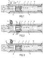
En se reportant aux figures on voit que, selon un premier mode de réalisation de l'invention, le vérin hydraulique comporte un piston 1 qui se déplace dans un cylindre constitué de deux tubes co-axiaux 2 et 3, qui ménagent entre eux un espace annulaire cylindrique 4.Referring to the figures, it can be seen that, according to a first embodiment of the invention, the hydraulic cylinder comprises a
Ledit espace annulaire 4 est relié à une source de gaz sous pression 6 à travers un clapet anti-retour 7 ; de telle sorte que la chambre 4 soit un volume clos, étanche, la pression du gaz étant permanente.Said
A la figure 1, on voit que le piston 1 et sa tige 10 peuvent se déplacer librement à l'intérieur du tube interne 2.In FIG. 1, it can be seen that the
A la figure 2, on voit que, après introduction du gaz sous pression dans l'espace annulaire 4, le tube 2 va exercer un effet de serrage sur le piston 1, selon les flèches f, ce qui va provoquer une déformation élastique de la paroi du tube interne 2, qui va venir serrer le piston 1 et l'immobiliser.In FIG. 2, it can be seen that, after introduction of the gas under pressure into the
Lorsque l'on introduit dans l'une ou l'autre des chambres 8 ou 9, situées de part et d'autre du piston, qui ne comporte pas de joint d'étanchéité, du liquide hydraulique sous pression, ce liquide va s'immiscer entre la paroi 2 du cylindre et la paroi externe du piston 1 en créant une contre-pression qui annule la déformation de ladite paroi 2.When one introduces into one or the other of the
Si l'on se reporte à la figure 3 on voit qu'il peut arriver, lorsque le piston est au voisinage d'une des extrémités du cylindre double 2/3 et que l'on introduit un fluide sous pression dans la chambre 8, par exemple, que la partie du tube 2 située de l'autre côté du piston, dans la chambre 9 ne soit pas suffisamment repoussée et que le blocage soit, au moins partiellement maintenu.Referring to FIG. 3, it can be seen that when the piston is in the vicinity of one end of the
Pour éviter cela on peut, avantageusement aménager une légère fuite de l'une à l'autre de la chambre par un très léger jeu permettant la présence d'un film d'huile (ou autre fluide hydraulique), ou bien par une rainure en spirale.To avoid this, it is advantageous to arrange a slight leakage from one to the other of the chamber by a very slight clearance allowing the presence of an oil film (or other hydraulic fluid), or by a groove in spiral.
La déformation du tube intérieur 2 est fonction de l'épaisseur de la paroi de ce tube, du métal employé et de la pression du gaz insufflé dans l'espace 4. Ces paramètres sont déterminés en fonction de l'usage auquel le vérin est destiné.The deformation of the
L'importance de la force de blocage du piston 1 est fonction de la pression du gaz et de l'importance des surfaces en contact. Ces paramètres seront également déterminés en fonction de l'usage auquel le vérin est destiné.The importance of the locking force of the
Il est donc possible grâce à cette disposition:
- de bloquer le piston en toute position
- de déterminer à volonté la force de blocage
- et de débloquer très facilement le piston.
- to lock the piston in any position
- to determine at will the blocking force
- and to unlock the piston very easily.
De plus il s'avère qu'il devient possible de réaliser un vérin équipé d'un piston sans joint d'étanchéité parce que, dès que la pression du fluide élimine le serrage du tube 2 sur le piston 1, ce dernier peut se déplacer librement ce qui permet de laisser un très faible jeu entre le piston 1 et le tube 2.Moreover, it turns out that it becomes possible to make a jack equipped with a piston without seal because, as soon as the fluid pressure eliminates the clamping of the
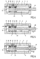
Les figures 4 à 6 concernent une variante de réalisation du vérin à blocage automatique.Figures 4 to 6 relate to an alternative embodiment of the self-locking cylinder.
Il peut se produire avec un vérin selon les figures 1 à 3 que le liquide hydraulique introduit sous pression, soit dans la grande chambre 8, soit dans la petite chambre 9 ne s'immisce pas de façon suffisante dans le jeu compris entre la paroi périphérique du piston 1 et la paroi interne du cylindre 2 ; de sorte que le contre-effort antagoniste, destiné à débloquer le vérin ne soit pas suffisant ou prenne trop de temps à s'établir.It can occur with a jack according to Figures 1 to 3 that the hydraulic fluid introduced under pressure, either in the
La variante illustrée aux figures 4 à 6 a pour objet de supprimer cet inconvénient.The variant illustrated in Figures 4 to 6 is intended to eliminate this disadvantage.
Dans ces figures les mêmes éléments portent les mêmes références.In these figures the same elements bear the same references.
Le piston 1 porte à chacune de ses extrémités des segments d'étanchéité 25-26 analogues aux segments utilisés dans les moteurs à combustion interne.The
En ces deux groupes de segments d'étanchéité 25 et 26 sont ménagées deux gorges annulaires 20 et 21, lesquelles sont reliées l'une à l'autre par un conduit 22, lequel communique avec les chambres 8 et 9 du vérin par les clapets anti-retour 23 et 24 en positions inversées.In these two groups of
Le fonctionnement de ce vérin est décrit ci-après.The operation of this cylinder is described below.
En position "verrouillée" (figure 4) la chambre annulaire cylindrique 4, qui est, en permanence, remplie d'un gaz neutre (azote) sous pression provoque la déformation élastique du tube interne 2, dont la paroi est relativement mince et déformable.In the "locked" position (FIG. 4) the cylindrical
Le piston 1 est alors coincé par le serrage exercé par la pression du gaz et ne peut plus se déplacer.The
Sur la figure 5 la chambre 8 est alimentée en liquide hydraulique sous pression par la conduite Pa. Ce liquide repousse le clapet anti-retour 24 et par la canalisation 22 alimente les gorges 20 et 21, ce qui permet à la contre-pression antagoniste de s'établir sur tout le pourtour du piston 1, d'annuler l'effet de la pression du gaz compris dans la chambre 4 ; de sorte que le piston 1 est déverrouillé et peut se déplacer dans la direction D1.In FIG. 5 the
Les segments d'étanchéité 25 et 26 permettent l'un et l'autre une légère fuite en début de mise en pression : cette fuite, s'additionnant à l'introduction de liquide sous pression par les gorges 20 et 21, facilite l'apparition d'un film d'huile sous pression entre la paroi du piston 1 et celle du tube 2.The
Sur la figure 6, c'est la petite chambre 9 qui est alimentée en liquide sous pression : le fonctionnement est identique à celui de la figure 5, mais en sens inverse : le piston est déverrouillé et se déplace selon la direction D2.In Figure 6, it is the
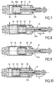
Les figures 7 à 10 représentent un autre mode de réalisation de l'invention qui fonctionne de façon inverse c'est-à-dire que ce n'est plus le cylindre qui vient serrer le piston en se rétractant de façon élastique mais le piston qui vient se serrer contre la paroi du cylindre en se dilatant.FIGS. 7 to 10 show another embodiment of the invention which operates in an inverse manner, that is to say that it is no longer the cylinder which presses the piston by retracting elastically but the piston which comes to tighten against the wall of the cylinder by expanding.
La figure 7 illustre une première position de verrouillage du vérin.Figure 7 illustrates a first locking position of the jack.
Le piston 30, porté par une tige 31, peut coulisser dans un cylindre 32. Le piston est creux et comporte une chambre 33 remplie d'un gaz neutre sous pression. La paroi 30a qui entoure la chambre 33 est relativement mince et déformable : sous l'effet de la pression du gaz se trouvant dans la chambre 33, cette paroi 30a se déforme et vient s'appliquer contre la paroi interne du cylindre 32 ; de sorte que le piston est bloqué.The
Sur la figure 8 on voit que du liquide hydraulique sous pression a été introduit dans la chambre 34. Ce liquide hydraulique sous pression s'immisce entre la paroi 30a du piston 30 et la paroi interne du cylindre 32 en créant une contre-pression antagoniste qui annule la déformation de ladite paroi 30a, ce qui libère le piston 30 qui peut se déplacer selon la flèche f1.FIG. 8 shows that pressurized hydraulic fluid has been introduced into the
A la figure 9, la pression hydraulique a été supprimée dans la chambre 34 ; il en résulte que la paroi 30a du piston 30 se déforme et ce dernier est à nouveau bloqué comme dans le cas de la figure 7.In Figure 9, the hydraulic pressure was removed in the
A la figure 10 la pression hydraulique est introduite dans la petite chambre 35. Le liquide hydraulique sous pression s'immisce entre la paroi 30a du piston 30 et la paroi interne du cylindre 32 en créant une contre-pression antagoniste qui annule la déformation de ladite paroi 30a, ce qui libère le piston 30 qui peut se déplacer selon la flèche f2.In FIG. 10, the hydraulic pressure is introduced into the
Pour faciliter la progression du liquide hydraulique sous pression entre la paroi 30a et la paroi interne du cylindre on peut graver sur la paroi 30a de petites rainures facilitant la progression du liquide hydraulique sous pression.To facilitate the progression of the hydraulic fluid under pressure between the wall 30a and the inner wall of the cylinder can be engraved on the wall 30a of small grooves facilitating the progression of the hydraulic fluid under pressure.
Dans tous les exemples décrits les chambres 4 ou 33 sont des volumes clos, étanches, en pression permanente mais on peut également disposer un clapet anti-retour comme le clapet 7 des figures 2 et 3 ou en disposer un dans la conduite 33a, située dans la tige du piston pour annuler la pression du gaz.In all the examples described, the
On peut également remplacer le gaz sous pression fixe par du gaz ou du fluide sous pression variable et pilotée par un circuit extérieur relié au vérin.It is also possible to replace the gas under fixed pressure by gas or fluid under variable pressure and controlled by an external circuit connected to the cylinder.
Ce type de vérin sera utilisé dans tous les cas où un vérin doit maintenir une charge sans changer de position et cela pendant un temps très long.This type of cylinder will be used in all cases where a cylinder must maintain a load without changing position and this for a very long time.
A titre d'exemple, non limitatif, un tel vérin peut être avantageusement employé pour la mise en position d'un radar mobile; de sorte que, une fois le radar réglé, sa position soit maintenue constante.By way of non-limiting example, such a cylinder can be advantageously used for positioning a mobile radar; so that once the radar is set, its position is kept constant.
Dans tous les exemples représentés le blocage du piston est obtenu par le fait que la chambre remplie de gaz est étanche et remplie en permanence de gaz sous pression ; mais il est bien évident que l'on peut obtenir le déblocage soit en annulant la pression de gaz par un clapet approprié, soit en remplaçant la pression de gaz par une pression de gaz ou de fluide variable et pilotée.In all the examples shown, the blocking of the piston is obtained by the fact that the chamber filled with gas is tight and permanently filled with gas under pressure; but it is obvious that one can obtain the unlocking either by canceling the gas pressure by a suitable valve, or by replacing the gas pressure by a gas pressure or variable and controlled fluid.
Les figures 11 et 12 illustrent un troisième mode de réalisation de l'invention.Figures 11 and 12 illustrate a third embodiment of the invention.
Le vérin est constitué par un cylindre 20, dans lequel coulisse un piston 21 solidaire d'une tige 22.The jack is constituted by a
Le piston 21 comporte une chambre annulaire 23 dont la paroi annulaire 24, en contact avec la paroi interne du cylindre 20 est déformable élastiquement.The
Cette chambre annulaire 23 est en communication avec la chambre 25 d'un accumulateur 26, disposé à l'intérieur du piston 21.This
Un moyen mécanique, constitué par une tige 27 coulissant à l'intérieur de la tige 22 du piston 21 peut venir repousser l'élément mobile de l'accumulateur 26 contre son ressort 29.A mechanical means consisting of a
Le mouvement de cette tige 27 peut être provoqué par tout dispositif approprié ; mais, dans l'exemple représenté il est provoqué par un petit piston 28, solidaire de la tige 27, commandé hydrauliquement.The movement of this
A la figure 11 on voit que le ressort 29 a complètement repoussé l'élément mobile de l'accumulateur 26, faisant régner dans la chambre 25 une haute pression hydraulique, qui est transmise à la chambre annulaire 23, ce qui a pour effet de déformer la paroi 24 et donc de bloquer le piston 21 dans son cylindre 20.In FIG. 11, it can be seen that the
A la figure 12 on voit que le petit piston 28 s'est déplacé selon la flèche f1 ; de sorte que la tige 27 a repoussé l'élément mobile de l'accumulateur 26 en comprimant le ressort 29. Il en résulte que la pression dans la chambre 25 a diminué, donc aussi dans la chambre 23, de sorte que la déformation de la paroi 24 a disparu, ce qui a débloqué le piston 21.In Figure 12 we see that the
Claims (15)
Applications Claiming Priority (1)
| Application Number | Priority Date | Filing Date | Title |
|---|---|---|---|
| FR0607819A FR2905428A1 (en) | 2006-09-06 | 2006-09-06 | HYDRAULIC CYLINDER WITH AUTOMATIC LOCK |
Publications (2)
| Publication Number | Publication Date |
|---|---|
| EP1898103A2 true EP1898103A2 (en) | 2008-03-12 |
| EP1898103A3 EP1898103A3 (en) | 2008-07-02 |
Family
ID=37876016
Family Applications (1)
| Application Number | Title | Priority Date | Filing Date |
|---|---|---|---|
| EP07291000A Withdrawn EP1898103A3 (en) | 2006-09-06 | 2007-08-10 | Hydraulic cylinder with automatic locking |
Country Status (3)
| Country | Link |
|---|---|
| US (1) | US7779745B2 (en) |
| EP (1) | EP1898103A3 (en) |
| FR (1) | FR2905428A1 (en) |
Cited By (2)
| Publication number | Priority date | Publication date | Assignee | Title |
|---|---|---|---|---|
| CN102979784A (en) * | 2012-12-10 | 2013-03-20 | 沈阳工业大学 | Hydraulic locking mechanism |
| WO2014177774A1 (en) * | 2013-04-30 | 2014-11-06 | Douce Hydro | System for blocking relative translational movement between two parts |
Families Citing this family (8)
| Publication number | Priority date | Publication date | Assignee | Title |
|---|---|---|---|---|
| US8523145B2 (en) * | 2009-04-02 | 2013-09-03 | Actuant Corporation | Jack assembly with integrated pressure relief assembly |
| US9127661B2 (en) * | 2010-10-25 | 2015-09-08 | Hamilton Sundstrand Corporation | Bootstrap accumulator system with telescoping actuator cylinder |
| CN104214165B (en) * | 2014-04-25 | 2016-04-13 | 东南大学 | A kind of dual-port support lock locking oil cylinder and controlling method thereof |
| DE102015101570B4 (en) * | 2015-02-04 | 2019-04-25 | Kraussmaffei Technologies Gmbh | Closing unit of a pillar injection molding machine |
| CN204607490U (en) * | 2015-03-04 | 2015-09-02 | 杭州盈江机械制造有限公司 | The hydraulic jack of load fast lifting |
| DE102016119636B3 (en) | 2016-10-14 | 2018-02-08 | Carl Zeiss Smart Optics Gmbh | Molding tool and use of the same |
| CN109534211B (en) * | 2019-01-24 | 2023-10-27 | 长江水利委员会长江科学院 | Flexible jack |
| KR102370177B1 (en) * | 2019-11-07 | 2022-03-04 | 서문원 | Braking system for Oil pressure cylinder apparatus |
Citations (5)
| Publication number | Priority date | Publication date | Assignee | Title |
|---|---|---|---|---|
| FR2196877A1 (en) | 1972-08-03 | 1974-03-22 | Spenklin Ltd | |
| DE3113894A1 (en) | 1981-04-07 | 1982-11-11 | H. Kuhnke Gmbh Kg, 2427 Malente | Working cylinder operated by pressure medium |
| US5355707A (en) | 1991-08-14 | 1994-10-18 | Kabushiki Kaisha Kobe Seiko Sho | Rolling mill and method for operating rolling mill |
| US5957443A (en) | 1998-07-20 | 1999-09-28 | Vektek, Inc. | Hydraulic work support |
| EP1079117A1 (en) | 1999-02-24 | 2001-02-28 | Pascal Kabushiki Kaisha | Hydraulic locking device |
Family Cites Families (3)
| Publication number | Priority date | Publication date | Assignee | Title |
|---|---|---|---|---|
| GB570897A (en) * | 1943-10-22 | 1945-07-27 | Messier Aircraft Equipment Ltd | Improvements in or relating to hydraulic jacks |
| US3575087A (en) * | 1968-11-18 | 1971-04-13 | Lourdes Ind Inc | Locking cylinder |
| US3665812A (en) * | 1969-07-01 | 1972-05-30 | Chukyo Electric Co | Apparatus for controlling rectilinear motion |
-
2006
- 2006-09-06 FR FR0607819A patent/FR2905428A1/en not_active Withdrawn
-
2007
- 2007-08-07 US US11/882,933 patent/US7779745B2/en not_active Expired - Fee Related
- 2007-08-10 EP EP07291000A patent/EP1898103A3/en not_active Withdrawn
Patent Citations (5)
| Publication number | Priority date | Publication date | Assignee | Title |
|---|---|---|---|---|
| FR2196877A1 (en) | 1972-08-03 | 1974-03-22 | Spenklin Ltd | |
| DE3113894A1 (en) | 1981-04-07 | 1982-11-11 | H. Kuhnke Gmbh Kg, 2427 Malente | Working cylinder operated by pressure medium |
| US5355707A (en) | 1991-08-14 | 1994-10-18 | Kabushiki Kaisha Kobe Seiko Sho | Rolling mill and method for operating rolling mill |
| US5957443A (en) | 1998-07-20 | 1999-09-28 | Vektek, Inc. | Hydraulic work support |
| EP1079117A1 (en) | 1999-02-24 | 2001-02-28 | Pascal Kabushiki Kaisha | Hydraulic locking device |
Cited By (4)
| Publication number | Priority date | Publication date | Assignee | Title |
|---|---|---|---|---|
| CN102979784A (en) * | 2012-12-10 | 2013-03-20 | 沈阳工业大学 | Hydraulic locking mechanism |
| CN102979784B (en) * | 2012-12-10 | 2016-05-25 | 沈阳工业大学 | A kind of hydraulic locking mechanism |
| WO2014177774A1 (en) * | 2013-04-30 | 2014-11-06 | Douce Hydro | System for blocking relative translational movement between two parts |
| US9976578B2 (en) | 2013-04-30 | 2018-05-22 | Douce Hydro | System for blocking relative translational movement between two parts |
Also Published As
| Publication number | Publication date |
|---|---|
| FR2905428A1 (en) | 2008-03-07 |
| US20080054239A1 (en) | 2008-03-06 |
| US7779745B2 (en) | 2010-08-24 |
| EP1898103A3 (en) | 2008-07-02 |
Similar Documents
| Publication | Publication Date | Title |
|---|---|---|
| EP1898103A2 (en) | Hydraulic cylinder with automatic locking | |
| EP2591273B1 (en) | Filling connector, corresponding container and corresponding filling method | |
| EP2737234B1 (en) | Filling connector, container, filling method and filling nozzle | |
| EP3265716B1 (en) | Valve, receptacle and method for filling, extracting and evacuating | |
| FR2546265A1 (en) | PIPE CONNECTION | |
| FR2704924A1 (en) | Pyrotechnic valve. | |
| WO2010089490A1 (en) | Device for selectively blocking a fluid passage | |
| LU87748A1 (en) | DEVICE FOR NEUTRALIZING A RESIDUAL PRESSURE VALVE OF A GAS BOTTLE | |
| EP3708899A1 (en) | Valve, container for pressurised fluid and filling and extraction methods | |
| EP0239451A1 (en) | Check valve, especially for a pressurised-water reactor | |
| FR2731071A1 (en) | DIFFERENTIAL PRESSURE INDICATOR | |
| FR2674042A1 (en) | HYDRAULIC DEVICE AND PNEUMATIC BLOCKING DEVICE. | |
| FR2547015A1 (en) | ACTUATOR WITH PNEUMATIC ENERGY ACCUMULATOR, IN PARTICULAR FOR TAPS | |
| EP1092093B1 (en) | Membrane pump and membrane therefor | |
| FR2779194A1 (en) | Piston/cylinder pneumatic spring | |
| EP3519322B1 (en) | Device for dispensing a pressurised material | |
| FR3101125A1 (en) | Packaging device, assembly comprising such a device and a container, its use and a method for filling or withdrawing | |
| EP3708900B1 (en) | Connector for pressurised fluid, valve and container comprising such a connector and connection method | |
| BE1012724A3 (en) | Linear motor for air control valve cryogenic. | |
| EP2992224B1 (en) | System for blocking relative translational movement between two parts | |
| EP4305328A1 (en) | Expansion valve comprising a movable slide | |
| FR2552514A1 (en) | DAMPER OF THE FLUIDIC TYPE | |
| WO1997046442A1 (en) | Hydraulic spring compressor | |
| FR2578944A1 (en) | FLEXIBLE PISTON SAFETY VALVE FOR PETROL OPERATING WELL | |
| FR2697606A1 (en) | Valve for controlling the flow of a fluid under pressure through the passage section between two inlet and outlet ducts. |
Legal Events
| Date | Code | Title | Description |
|---|---|---|---|
| PUAI | Public reference made under article 153(3) epc to a published international application that has entered the european phase |
Free format text: ORIGINAL CODE: 0009012 |
|
| AK | Designated contracting states |
Kind code of ref document: A2 Designated state(s): AT BE BG CH CY CZ DE DK EE ES FI FR GB GR HU IE IS IT LI LT LU LV MC MT NL PL PT RO SE SI SK TR |
|
| AX | Request for extension of the european patent |
Extension state: AL BA HR MK YU |
|
| PUAL | Search report despatched |
Free format text: ORIGINAL CODE: 0009013 |
|
| AK | Designated contracting states |
Kind code of ref document: A3 Designated state(s): AT BE BG CH CY CZ DE DK EE ES FI FR GB GR HU IE IS IT LI LT LU LV MC MT NL PL PT RO SE SI SK TR |
|
| AX | Request for extension of the european patent |
Extension state: AL BA HR MK RS |
|
| 17P | Request for examination filed |
Effective date: 20080920 |
|
| AKX | Designation fees paid |
Designated state(s): AT BE BG CH CY CZ DE DK EE ES FI FR GB GR HU IE IS IT LI LT LU LV MC MT NL PL PT RO SE SI SK TR |
|
| GRAP | Despatch of communication of intention to grant a patent |
Free format text: ORIGINAL CODE: EPIDOSNIGR1 |
|
| STAA | Information on the status of an ep patent application or granted ep patent |
Free format text: STATUS: THE APPLICATION IS DEEMED TO BE WITHDRAWN |
|
| 18D | Application deemed to be withdrawn |
Effective date: 20130301 |